EP4067732A1 - Vehicle light with a luminous surface comprising a reflector surface - Google Patents
Vehicle light with a luminous surface comprising a reflector surface Download PDFInfo
- Publication number
- EP4067732A1 EP4067732A1 EP21166510.4A EP21166510A EP4067732A1 EP 4067732 A1 EP4067732 A1 EP 4067732A1 EP 21166510 A EP21166510 A EP 21166510A EP 4067732 A1 EP4067732 A1 EP 4067732A1
- Authority
- EP
- European Patent Office
- Prior art keywords
- light
- reflector
- light source
- reflective coating
- vehicle
- Prior art date
- Legal status (The legal status is an assumption and is not a legal conclusion. Google has not performed a legal analysis and makes no representation as to the accuracy of the status listed.)
- Withdrawn
Links
Images


Classifications
-
- F—MECHANICAL ENGINEERING; LIGHTING; HEATING; WEAPONS; BLASTING
- F21—LIGHTING
- F21S—NON-PORTABLE LIGHTING DEVICES; SYSTEMS THEREOF; VEHICLE LIGHTING DEVICES SPECIALLY ADAPTED FOR VEHICLE EXTERIORS
- F21S41/00—Illuminating devices specially adapted for vehicle exteriors, e.g. headlamps
- F21S41/30—Illuminating devices specially adapted for vehicle exteriors, e.g. headlamps characterised by reflectors
- F21S41/37—Illuminating devices specially adapted for vehicle exteriors, e.g. headlamps characterised by reflectors characterised by their material, surface treatment or coatings
-
- B—PERFORMING OPERATIONS; TRANSPORTING
- B60—VEHICLES IN GENERAL
- B60Q—ARRANGEMENT OF SIGNALLING OR LIGHTING DEVICES, THE MOUNTING OR SUPPORTING THEREOF OR CIRCUITS THEREFOR, FOR VEHICLES IN GENERAL
- B60Q1/00—Arrangement of optical signalling or lighting devices, the mounting or supporting thereof or circuits therefor
- B60Q1/26—Arrangement of optical signalling or lighting devices, the mounting or supporting thereof or circuits therefor the devices being primarily intended to indicate the vehicle, or parts thereof, or to give signals, to other traffic
- B60Q1/2607—Arrangement of optical signalling or lighting devices, the mounting or supporting thereof or circuits therefor the devices being primarily intended to indicate the vehicle, or parts thereof, or to give signals, to other traffic comprising at least two indicating lamps
-
- F—MECHANICAL ENGINEERING; LIGHTING; HEATING; WEAPONS; BLASTING
- F21—LIGHTING
- F21S—NON-PORTABLE LIGHTING DEVICES; SYSTEMS THEREOF; VEHICLE LIGHTING DEVICES SPECIALLY ADAPTED FOR VEHICLE EXTERIORS
- F21S41/00—Illuminating devices specially adapted for vehicle exteriors, e.g. headlamps
- F21S41/60—Illuminating devices specially adapted for vehicle exteriors, e.g. headlamps characterised by a variable light distribution
- F21S41/65—Illuminating devices specially adapted for vehicle exteriors, e.g. headlamps characterised by a variable light distribution by acting on light sources
- F21S41/663—Illuminating devices specially adapted for vehicle exteriors, e.g. headlamps characterised by a variable light distribution by acting on light sources by switching light sources
-
- F—MECHANICAL ENGINEERING; LIGHTING; HEATING; WEAPONS; BLASTING
- F21—LIGHTING
- F21S—NON-PORTABLE LIGHTING DEVICES; SYSTEMS THEREOF; VEHICLE LIGHTING DEVICES SPECIALLY ADAPTED FOR VEHICLE EXTERIORS
- F21S43/00—Signalling devices specially adapted for vehicle exteriors, e.g. brake lamps, direction indicator lights or reversing lights
- F21S43/10—Signalling devices specially adapted for vehicle exteriors, e.g. brake lamps, direction indicator lights or reversing lights characterised by the light source
- F21S43/13—Signalling devices specially adapted for vehicle exteriors, e.g. brake lamps, direction indicator lights or reversing lights characterised by the light source characterised by the type of light source
- F21S43/14—Light emitting diodes [LED]
-
- F—MECHANICAL ENGINEERING; LIGHTING; HEATING; WEAPONS; BLASTING
- F21—LIGHTING
- F21S—NON-PORTABLE LIGHTING DEVICES; SYSTEMS THEREOF; VEHICLE LIGHTING DEVICES SPECIALLY ADAPTED FOR VEHICLE EXTERIORS
- F21S43/00—Signalling devices specially adapted for vehicle exteriors, e.g. brake lamps, direction indicator lights or reversing lights
- F21S43/20—Signalling devices specially adapted for vehicle exteriors, e.g. brake lamps, direction indicator lights or reversing lights characterised by refractors, transparent cover plates, light guides or filters
- F21S43/235—Light guides
- F21S43/236—Light guides characterised by the shape of the light guide
- F21S43/239—Light guides characterised by the shape of the light guide plate-shaped
-
- F—MECHANICAL ENGINEERING; LIGHTING; HEATING; WEAPONS; BLASTING
- F21—LIGHTING
- F21S—NON-PORTABLE LIGHTING DEVICES; SYSTEMS THEREOF; VEHICLE LIGHTING DEVICES SPECIALLY ADAPTED FOR VEHICLE EXTERIORS
- F21S43/00—Signalling devices specially adapted for vehicle exteriors, e.g. brake lamps, direction indicator lights or reversing lights
- F21S43/20—Signalling devices specially adapted for vehicle exteriors, e.g. brake lamps, direction indicator lights or reversing lights characterised by refractors, transparent cover plates, light guides or filters
- F21S43/235—Light guides
- F21S43/242—Light guides characterised by the emission area
- F21S43/243—Light guides characterised by the emission area emitting light from one or more of its extremities
-
- F—MECHANICAL ENGINEERING; LIGHTING; HEATING; WEAPONS; BLASTING
- F21—LIGHTING
- F21S—NON-PORTABLE LIGHTING DEVICES; SYSTEMS THEREOF; VEHICLE LIGHTING DEVICES SPECIALLY ADAPTED FOR VEHICLE EXTERIORS
- F21S43/00—Signalling devices specially adapted for vehicle exteriors, e.g. brake lamps, direction indicator lights or reversing lights
- F21S43/20—Signalling devices specially adapted for vehicle exteriors, e.g. brake lamps, direction indicator lights or reversing lights characterised by refractors, transparent cover plates, light guides or filters
- F21S43/235—Light guides
- F21S43/247—Light guides with a single light source being coupled into the light guide
-
- F—MECHANICAL ENGINEERING; LIGHTING; HEATING; WEAPONS; BLASTING
- F21—LIGHTING
- F21S—NON-PORTABLE LIGHTING DEVICES; SYSTEMS THEREOF; VEHICLE LIGHTING DEVICES SPECIALLY ADAPTED FOR VEHICLE EXTERIORS
- F21S43/00—Signalling devices specially adapted for vehicle exteriors, e.g. brake lamps, direction indicator lights or reversing lights
- F21S43/20—Signalling devices specially adapted for vehicle exteriors, e.g. brake lamps, direction indicator lights or reversing lights characterised by refractors, transparent cover plates, light guides or filters
- F21S43/26—Refractors, transparent cover plates, light guides or filters not provided in groups F21S43/235 - F21S43/255
-
- F—MECHANICAL ENGINEERING; LIGHTING; HEATING; WEAPONS; BLASTING
- F21—LIGHTING
- F21S—NON-PORTABLE LIGHTING DEVICES; SYSTEMS THEREOF; VEHICLE LIGHTING DEVICES SPECIALLY ADAPTED FOR VEHICLE EXTERIORS
- F21S43/00—Signalling devices specially adapted for vehicle exteriors, e.g. brake lamps, direction indicator lights or reversing lights
- F21S43/30—Signalling devices specially adapted for vehicle exteriors, e.g. brake lamps, direction indicator lights or reversing lights characterised by reflectors
- F21S43/33—Signalling devices specially adapted for vehicle exteriors, e.g. brake lamps, direction indicator lights or reversing lights characterised by reflectors characterised by their material, surface treatment or coatings
-
- B—PERFORMING OPERATIONS; TRANSPORTING
- B60—VEHICLES IN GENERAL
- B60Q—ARRANGEMENT OF SIGNALLING OR LIGHTING DEVICES, THE MOUNTING OR SUPPORTING THEREOF OR CIRCUITS THEREFOR, FOR VEHICLES IN GENERAL
- B60Q2400/00—Special features or arrangements of exterior signal lamps for vehicles
- B60Q2400/20—Multi-color single source or LED matrix, e.g. yellow blinker and red brake lamp generated by single lamp
Definitions
- the invention relates to a vehicle light according to the preamble of claim 1.
- a vehicle lamp comprises, for example, a lamp interior essentially enclosed by a lamp housing with at least one light opening and a lens closing it, and at least one illuminant housed therein, comprising at least one light source, for at least one lighting function of the vehicle lamp.
- each vehicle light in particular an automobile light, fulfills one or more tasks or functions.
- a light function of the vehicle light is provided to fulfill each task or function.
- Light functions are, for example, a function that illuminates the roadway when configured as a headlight, or a signal function when configured as a signal light, such as a repeating flashing light function to indicate the direction of travel or a brake light function to indicate braking activity, or e.g. a parking light function, such as a rear light function, to ensure a Day and/or night visibility of the vehicle, such as when configured as a rear light or daytime running light.
- Each light function must fulfill a light distribution that is specified by law, for example.
- the light distribution determines at least luminous fluxes to be maintained, colloquially referred to as brightness, in at least solid angle ranges to be maintained.
- At least one light source of the illuminant of a vehicle lamp can be assigned one or more optical elements for light guidance that contribute to the formation of a light distribution.
- each light function When looking from outside the interior of the light onto the lens or through it, each light function is realized in such a way that each light function has its own or part of a common light area available at least while it is being performed at the moment.
- the lens is formed by a nowadays usually made of a plastic, transparent cover, which closes the interior of the lamp and protects the components housed therein, such as one or more lamps, reflectors and alternatively or additionally provided optics elements against weather influences.
- the lamp housing or the interior of the lamp can be divided into several chambers, each with their own light sources and/or illuminants and/or optics elements and possibly light panes, of which several chambers can have the same and/or each chamber can fulfill a different lighting function.
- the optical elements mentioned can be at least one reflector and/or at least one lens and/or one or more optical disks or the like arranged in the beam path between at least one light source of the illuminant and the lens.
- At least one reflector arranged behind at least one light source of at least one lamp can be accommodated in the interior of the lamp.
- Such a reflector which an observer can see through the lens from outside the interior of the lamp, forms at least part of the luminous surface of the vehicle lamp, at least partially surrounds it or is at least partially surrounded by the luminous surface.
- the reflector can be formed at least in part by a separate component and/or by at least part of the lamp housing itself, for example by means of an at least partially reflective coating.
- the lens itself can alternatively or additionally be designed as an optical element, for example by preferably having a light distribution on its inside that contributes to the generation of one or more light distributions mentioned above optical structure is provided. As a result, an optical disk can be dispensed with if necessary.
- vehicle lights are on the front of the vehicle, on the sides of the vehicle and/or on the side mirrors and on the rear of the vehicle, repeater flashing lights, exit lights, for example for ambient lighting, side lights, brake lights, fog lights, reversing lights, and typically high-mounted third brake lights, so-called central, high-mounted Braking lights, daytime running lights, headlights and fog lights used as cornering lights, and combinations thereof.
- Such a combination is, for example, regularly implemented in the known rear lights.
- repeat turn signal lights, position lights, brake lights, fog lights and reversing lights are used, to name just one of many combinations implemented in rear lights. This list does not claim to be complete, nor does it mean that all of the lights mentioned must be combined in one rear light. For example, only two or three of the lights mentioned or other lights can also be combined with one another in a common light housing of a rear light.
- One object of the invention is to develop a vehicle light with a common lighting area for at least two light functions of any light color.
- One object of the invention therefore relates to a vehicle lamp with a lamp interior that is at least partially enclosed by a lamp housing and a lens, in which a reflector is at least partially housed, which forms and/or comprises at least part of a luminous surface for realizing a lighting function of the vehicle lamp, or is comprised of a luminous surface for realizing a light function of the vehicle lamp.
- the reflector comprises a reflector body that is transparent at least for light in a part of the electromagnetic spectrum that is at least visible to the human eye and has a reflector surface that preferably faces at least partially both the lens and a first light source that emits light to be reflected.
- the reflector surface is partially covered with a reflective coating.
- a remaining part of the reflector surface is designed free of the reflective coating.
- the first light source radiates its light into the reflector, which is comprised of the luminous surface for two light functions.
- the reflector deflects the light from the first light source in the direction of the lens.
- a second light source radiates its light from a side facing away from the reflector surface through the reflector body and through the areas of the reflector surface free of the reflective coating in the direction of the lens.
- the remaining part of the reflector surface that is free of the reflective coating can be freed from the reflective coating, for example, by laser cutting.
- the reflector surface is initially provided with a reflective coating over its entire surface, which is partially removed by free lasering in the remaining part of the reflector surface that is free of the reflective coating.
- the second light source radiates its light through the areas of the reflector surface that have been lasered free of the reflective coating.
- the invention preferably provides that a first light source radiates its light into a reflector that forms the luminous surface for two light functions or is enclosed by the luminous surface for two light functions, with a second light source radiating its light through areas that have been lasered free of the reflective coating .
- Advantages over the prior art include a saving in installation space and weight. Additional advantages are the implementation of at least two light functions of any light color within one and the same luminous area. An additional advantage is the creation of a possibility for displaying symbols and characters, for example warnings within a luminous area.
- An advantageous development of the invention deals with the lasering of parts of a previously mirrored surface of an optical element that is transparent at least in a part of the electromagnetic spectrum that is visible to the human eye, with the aim of using the remaining mirrored partial surface of the optical element as a reflector for a first , their light into the reflector to provide the light function realized by the incident light source, and to provide the partial surface of the optical element freed from the reflective coating as an attachment optical element for a light function realized by a second light source that transmits its light through the optical element, at least in the region of the partial surface freed from the reflective coating optically effective structures, such as lens geometries or the like, are applied to the side of the optical element facing the second light source, as a result of which the first and second light functions have different light distributions.
- the light function that shines through is the light function that is realized by the light emitted by the second light source.
- a particularly advantageous development of the invention therefore provides that at least the lasered areas on a side facing the second light source are provided with optically active structures influencing the light distribution of the light radiated through by the second light source.
- the side facing the second light source is the side facing away from the reflector surface, from which the second light source radiates its light through the reflector body and through the areas of the reflector surface free of the reflective coating in the direction of the lens.
- the luminous surface area through which the second light source radiates its light can accordingly be optically structured.
- the optical structuring can be provided on the front and/or rear.
- An advantageous development of the invention provides for free lasering and coding of surfaces, for example free lasering of surfaces to generate at least two light functionalities in an optically structured luminous surface area.
- the invention can be implemented by lasering parts of a reflective coating on a reflector surface with the aim of realizing additional light effects within a luminous surface that is available for one or two light functions of the same light color and includes the reflective coating.
- the vehicle light can have individual or a combination of several features described in the introduction in connection with the prior art and/or in one or more of the documents mentioned on the prior art and/or in the following description of the exemplary embodiments illustrated in the drawings .
- the invention thus creates expanded possibilities for structuring optical elements after they have been vapor-deposited. It also creates extended and more flexible options for displaying lettering, logos, etc., especially in vehicle lights such as automotive lights and headlights. These are, for example, extended and more flexible options for the display of lettering, logos, etc., so that they are compliant with the legal regulations to be observed for automotive lights, such as ECE, FMVSS, SAE, etc., and can be used.
- the invention enables integration of a plurality of light signatures into one and the same visible luminous surface in lights, for example formed by one or more reflectors, optical discs, light discs, etc. or comprised by or comprising such.
- stenciled vapor deposition can be dispensed with.
- Such stenciled vaporizations are associated with limitations that result, for example, from the fact that a shadow mask has to be used whose areas are contiguous have to. For example, for the recess in the shape of a letter "O", the shadow mask must also be inside the "O”. Therefore, connecting webs from outside to inside the "O” are required, which have negative effects on the "O" contour, since interruptions in the contour are required.
- the vehicle light 01 shown in whole or in part comprises a light interior 04 that is at least partially enclosed by a light housing 02 and a lens 03.
- a reflector 05 is accommodated at least in part in the interior space 04 of the lamp.
- Reflector 05 forms and/or comprises at least part of a luminous surface for implementing at least one lighting function of vehicle light 01, or it is surrounded by a luminous surface for implementing a lighting function of vehicle light 01.
- the reflector 05 comprises a reflector body 50 that is transparent at least to light in a part of the electromagnetic spectrum that is at least visible to the human eye and has a reflector surface 51 that preferably faces both the lens 03 and a first light source 06, which at least partially faces the light to be reflected.
- the reflector surface 51 is partially provided with a reflective coating. A remaining part 52 of the reflector surface 51 is designed free of the reflective coating.
- the already mentioned first light source 06 radiates its light into the reflector 05 by radiating its light onto the reflector surface 51 which is covered by the luminous surface for two light functions, for example.
- In 12 is the optical path of the of the the light emitted by the first light source 06 is illustrated by way of example by the marginal rays shown in dashed lines.
- a second light source 07 radiates its light from a side facing away from reflector surface 51 through reflector body 50 and through remaining part 52 of reflector surface 51, which is divided into several areas free of the reflective coating, for example in the direction of lens 03.
- the beam path of the light emitted by the second light source 07 is also shown as an example by marginal rays drawn in with dots.
- the reflector 05 preferably deflects the light from the first light source 06 in the direction of the lens 03.
- the second light source 07 radiates its light through the reflector body 50 and through the remaining part 52 of the reflector surface 51, which is divided into several areas free of the reflective coating, for example also preferably in the direction of the lens 03.
- the first light source 06 can be part of a first light source 60 comprising a conductor track carrier and optionally one or more electronic components.
- a first light source 60 can include a plurality of first light sources 06.
- the second light source 07 can be part of a second light source 70 comprising a conductor track carrier and optionally one or more electronic components.
- a second light source 70 can also include a plurality of second light sources 07.
- the first light source 06 and/or the second light source 07 can advantageously be embodied as semiconductor light sources.
- Semiconductor light sources such as LEDs (inorganic light-emitting diodes) and/or OLEDs (organic light-emitting diodes) have a very short, barely measurable activation time from the start of current application to the emission of light. In contrast to an incandescent lamp, the light is emitted with full luminosity proportional to the current intensity from the moment the current is applied. In addition, they are highly efficient in converting electrical current into light visible to the human eye. Furthermore, LEDs in particular have a very long service life when used in vehicle lights.
- the reflector surface 51 is initially provided with a reflective coating over its entire surface, which is partially removed again by free lasering in the remaining part 52 of the reflector surface 51 that is free of the reflective coating.
- the second light source 07 radiates its light through the areas of the reflector surface 51 that have been lasered free of the reflective coating.
- a first light source 06 radiates its light into a reflector 05 that forms the luminous surface for one or more, for example for two, lighting functions or is comprised by the luminous surface for one or more, preferably for two, lighting functions, with one second light source 07 transmits its light through areas that have been lasered free of the reflective coating.
- this allows the display of logos/warning notices, for example, within the luminous area formed by the reflector surface 51, for example by activating only one light function.
- the entire luminous surface surrounding and/or surrounded by the reflector 05 lights up in the light color.
- a logo that is visible in the switched-off state can be displayed on the reflector 05 by appropriately fine structuring.
- first light source 06 and the second light source 07 have different light colors
- logos and/or warnings can also be displayed within the luminous area formed by the reflector surface 51, even if both light functions are activated at the same time.
- Advantages over the prior art include a saving in installation space and weight. Additional advantages are the implementation of at least two light functions of any light color within one and the same luminous area. An additional advantage is the creation of a possibility for displaying symbols and characters, for example warnings within a luminous area.
- the new type of vehicle light 01 makes it possible to design new light functionalities, for example through partial laser ablation of, for example, vapour-coated surfaces and, alternatively or additionally, flexible adaptation of light signatures through dedicated lighting of components.
- 1 and 12 show the possibility of using the reflector 05 for a light function when it is irradiated from above with the first light source 06, which is implemented, for example, by a plurality of LEDs, and on the other hand as an alternative light function, when the second light source 07, which is also implemented, for example, by a plurality of LEDs, from behind is used - possibly also together with the LEDs of the first light source 06 that shine in from above.
- the individual areas of the remaining part 52 of the reflector surface 51 which is free of the reflective coating, or generally on an optical element made of a transparent body with a surface partially provided with a reflective coating, are selected to be sufficiently small, it is no longer visible to the observer from a corresponding distance recognizable that incomplete visual signatures are displayed on the reflector. This is the case in particular when viewing in the so-called far field from a distance of preferably 10 m to the light function. A homogeneous light signature can therefore also be realized with such configurations.
- first and second light sources 06, 07 realized for example by several LEDs, of the respective other light function also light up with low intensity in order to make the gaps in the light signature less noticeable. This is particularly advantageous for near-field viewing from a distance of less than 10 m.
- both areas are then activated for the display, so that the luminances of the transparent and the reflective areas approach one another.
- the back-injection molding of a printed film is disadvantageous because a directed, metallically reflecting surface can only be produced as a printed pattern with difficulty.
- the further description is based on the example of a light function with reflector 05.
- logos and/or design elements should be placed on such a reflector 05, which are visible when the light function is switched off but not visible when it is switched on.
- the logo or design element on the reflector is not lasered over the entire surface, but only as a fine dot pattern 53, as in 8 , 9 , 10 , 11 shown.
- the remaining part 52 of the reflector surface 51 is designed as a dot pattern 53 .
- Such a pattern of small non-metallized areas cannot be produced with conventional methods.
- the dot pattern 53 is visible as a logo and/or design element on the reflector 05.
- the small, non-reflecting areas are completely outshone when the lighting is switched on, so that at least in the far field only a homogeneously illuminated area is visually perceptible.
- the design can be such that instead of individual prisms, individually reflecting areas are used.
- the result can be designed in such a way that the light signature is executed accordingly.
- a logo or design element with such a design can still be visible up to a certain maximum distance in the near field even when illuminated.
- This maximum distance will turn out to be smaller in the illuminated state than in the case of ambient light in the unilluminated state if non-reflecting, lasered points of the point pattern 53 occur instead of the luminous decoupling prisms.
- the appearance is then inverted compared to an embodiment with luminous decoupling prisms.
- the then non-illuminating dots of the dot pattern 53 are outshined by the luminous surrounding surface, so that they disappear even at a relatively small viewing distance.
- the lasered area in the area of the lettering and/or logo and/or design element is not the same as the lasered area outside of the lettering and/or logo and/or design element, but areas are also lasered there in order to achieve a more homogeneous overall appearance when illuminated achieve without reducing the visibility of the lettering and/or logo and/or design elements too much when switched off.
- vehicle lamp 01 provides that at least one section of reflector body 50, through which section the second light source 07 transmits its light from the side facing away from reflector surface 51, through reflector body 50 and through that part 52 of the reflector surface that is free of the reflective coating 51 preferably shines through in the direction of the lens 03, is provided with optically active structures that influence the light distribution of the light that is radiated through the section by the second light source 07.
- a particularly advantageous development therefore provides that at least the remaining part 52 of the reflector surface 51, which is free of the reflective coating, for example the lasered areas of a reflector surface 51 that was previously mirrored over its entire surface, should be on a side lying in the beam path of the second light source 07 and facing it the light distribution of the light radiated through by the second light source 07 is provided with optically active structures.
- the side facing the second light source 07 is the side facing away from the reflector surface 51, from which the second light source 07 transmits its light through the reflector body 50 and through the light from the reflective coating 51 free areas of the reflector surface 51 radiates through, for example in the direction of lens 03.
- the luminous surface area through which the second light source 07 radiates its light can therefore be optically structured for the purpose of influencing the light distribution of the light passing through the luminous surface area.
- Such a different influencing of the light distribution of the light emitted by the first light source 06 and the light distribution of the light emitted by the second light source 07 is in 12 by a schematic representation of a different widening of the beam path of the light emitted by the first light source 06, for example by marginal rays drawn in dashed lines, and of the beam path of the light emitted by the second light source 07, also shown by way of example by marginal rays drawn in dashed lines.
- optically active structures that are designed, for example, as optical structuring and/or include such structures can be arranged on the front and/or rear of the reflector body 50 with respect to the light from the second light source 07 passing through it.
- This advantageous further development of the invention provides, for example, for parts of a previously mirrored surface forming a reflector surface to be lasered free of an optical element which forms a reflector body and is transparent at least in a part of the electromagnetic spectrum that is visible to the human eye, with the aim of removing the remaining part Provide the surface of the optical element as a reflector for a light function realized by a first light source, which radiates its light into the reflector, and to provide the part of the optical element with the partial surface freed from the mirror coating as an attachment optical element for a light function realized by a second light source , which transmits its light through the optical element.
- optically effective structures designed and/or comprising such an optical structuring can comprise lens geometries and/or fields.
- Optically active structures such as lens geometries or the like, can advantageously be applied at least in the area of the partial surface that is spared or, for example, freed from the mirror coating on the side of the reflector 05 that forms an optical element that faces the second light source 07.
- the first and the second light function have different light distributions.
- the advantageous development of the invention thus supplements the configurations described above with the aspect that the light function passing through it passes through macroscopic optical elements such as lenses or optically effective structures formed by microlens arrays, which causes an adaptation of the light distribution of the light function passing through.
- the light function that shines through is the light function that is implemented by the light emitted by the second light source 07 .
- the exemplary embodiment shown also shows in particular the possibility of using the reflector 05, more precisely its reflector surface 51, as a luminous surface for a tail light function referred to as SL (tail light) for short, when it is irradiated from above with light from the first light source 06 implemented by LEDs, and on the other hand as a luminous surface for a brake light function referred to as BRL (brake light) for short, if the LEDs that implement the second light source 07 are used from behind.
- SL tail light
- BRL brake light
- a “BRL booster” can also be implemented, including the LEDs of the first light source 06.
- narrower light distributions can be realized for the representation of BRL functions and further emission areas can be realized for SL according to the reflective areas on the reflector element. It is thus possible to decouple the areas and functions.
- a reflector 05 with a partially lasered reflector surface 51, with a remaining part 52 of the reflector surface 51, which is subdivided, for example, into several areas and is free of the reflective coating, through which one or more second light sources 07 shine from behind becomes.
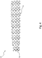
- the divided into several areas Remaining part 52 of the reflector surface 51, which is designed to be free of the reflective coating, can, for example, like an in 4 shown checkerboard pattern be executed.
- the remaining part 52 can also be distributed over a number of sub-areas of a reflector surface 51 distributed over a number of reflector vanes.
- Each field of the checkerboard pattern lasered free of the reflective coating has its own transparent lens arranged in the beam path of the light emitted from the second light source 07 through the reflector body 50 and the remaining part 52 of the reflector surface 51 that has been lasered free.
- a faceted optic can be formed here.
- the light is shaped by the transparent optics on the reflector 05 according to a given wish;
- the reflector substrate from which the reflector body 50 is made is transparent.
- the reflector 05 was first vaporized over its entire surface on its reflector surface 51 .
- the reflector 05 was then partially lasered free on its reflector surface 51, so that the reflective coating, for example made of aluminum, has disappeared in these areas and the transparent reflector substrate reappears.
- the remaining part 52 of the reflector surface 51 that is free of the reflective coating is subsequently formed after the full-area vaporization.
- the reflector surface 51 of a transparent reflector body 50 can first be vaporized over its entire surface. After the vapor deposition, the reflector 05 can be partially lasered free in the mentioned area of its reflector surface 51.
- An advantageous development of the invention provides for free lasering and coding of surfaces, for example free lasering of surfaces to generate at least two light functionalities in an optically structured luminous surface area.
- the remaining part 52 of the reflector surface 51 that is free of the reflective coating is designed, for example, in the shape of its outline and/or shape and/or geometry according to a coding of a light signature.
- the vehicle lamp 01 can comprise at least two lamps 60, 70, each comprising at least one light source 06, 07, a first lamp 60 with at least the first light source 06 to fulfill at least one first lighting function of the vehicle lamp 01, and a second lamp with at least the second light source 07 to fulfill at least one second lighting function of the vehicle lamp 01.
- the at least one first light source 06 and the at least one second light source 07 can advantageously be operated independently of one another.
- the invention can be implemented by lasering parts of a reflective coating of a reflector surface 51 with the aim of realizing additional light effects within a luminous surface that is available for one or two light functions of the same or different light color and that includes the reflective coating.
- the invention expands the prior art in that a first light source radiates its light into a reflector forming the luminous surface for two light functions, and that a second light source transmits its light through areas lasered free of the reflective coating. This allows the display of logos and/or warnings, for example, through the free design of the lasered areas.
- the invention expands the design freedom of lights and creates new possibilities, particularly in the design of light signatures and the coding of light signatures.
- the invention significantly expands the design options for optical systems.
- the vehicle light 01 can alternatively or additionally be individual or a combination of several, introduced in connection with the prior art and/or in one or more of the documents mentioned as prior art and/or the features mentioned in the preceding description and/or in the following claims.
- the invention is not limited by the description based on the exemplary embodiments. Rather, the invention encompasses every new feature and every combination of features, which in particular includes every combination of features in the claims, even if this feature or this combination itself is not explicitly specified in the claims or exemplary embodiments.
- the invention can be used commercially in particular in the field of manufacturing vehicle lights, in particular motor vehicle lights.
Landscapes
- Engineering & Computer Science (AREA)
- General Engineering & Computer Science (AREA)
- Physics & Mathematics (AREA)
- Microelectronics & Electronic Packaging (AREA)
- Optics & Photonics (AREA)
- Mechanical Engineering (AREA)
- Non-Portable Lighting Devices Or Systems Thereof (AREA)
Abstract
Es wird eine Fahrzeugleuchte (01) mit einem von einem Leuchtengehäuse (02) und einer Lichtscheibe (03) wenigstens zum Teil umschlossenen Leuchteninnenraum (04) beschrieben. Der Leuchteninnenraum beherbergt einen Reflektor (05) wenigstens zum Teil. Der Reflektor (05) umfasst zumindest einen Teil einer Leuchtfläche zur Verwirklichung wenigstens einer Lichtfunktion der Fahrzeugleuchte (01). Der Reflektor (05) umfasst einen zumindest für Licht in einem zumindest für das menschliche Auge sichtbaren Teil des elektromagnetischen Spektrums transparenten Reflektorkörper (50) mit einer Reflektoroberfläche (51). Die Reflektoroberfläche (51) ist zum Teil mit einer reflektierenden Beschichtung versehen. Ein verbleibender Teil (52) der Reflektoroberfläche (51) ist frei von der reflektierenden Beschichtung ausgeführt. Eine erste Lichtquelle (06) strahlt ihr Licht auf die Reflektoroberfläche (51) ein. Eine zweite Lichtquelle (07) strahlt ihr Licht von einer der Reflektoroberfläche (51) abgewandten Seite durch den Reflektorkörper (50) und durch den verbleibenden Teil (52) der Reflektoroberfläche (51) hindurch.A vehicle lamp (01) is described with a lamp interior (04) at least partially enclosed by a lamp housing (02) and a lens (03). The interior of the lamp houses a reflector (05), at least in part. The reflector (05) comprises at least part of a luminous surface for realizing at least one lighting function of the vehicle light (01). The reflector (05) comprises a reflector body (50) that is transparent at least to light in a part of the electromagnetic spectrum that is visible to the human eye and has a reflector surface (51). The reflector surface (51) is partially provided with a reflective coating. A remaining part (52) of the reflector surface (51) is free of the reflective coating. A first light source (06) radiates its light onto the reflector surface (51). A second light source (07) radiates its light from a side facing away from the reflector surface (51) through the reflector body (50) and through the remaining part (52) of the reflector surface (51).
Description
Die Erfindung betrifft eine Fahrzeugleuchte gemäß dem Oberbegriff des Anspruchs 1.The invention relates to a vehicle light according to the preamble of claim 1.
Eine Fahrzeugleuchte umfasst beispielsweise einen im Wesentlichen von einem Leuchtengehäuse mit mindestens einer Lichtöffnung und einer diese verschließenden Lichtscheibe umschlossenen Leuchteninnenraum und mindestens ein darin beherbergtes, mindestens eine Lichtquelle umfassendes Leuchtmittel für wenigstens eine Lichtfunktion der Fahrzeugleuchte.A vehicle lamp comprises, for example, a lamp interior essentially enclosed by a lamp housing with at least one light opening and a lens closing it, and at least one illuminant housed therein, comprising at least one light source, for at least one lighting function of the vehicle lamp.
Jede Fahrzeugleuchte, insbesondere Automobilleuchte, erfüllt je nach Ausgestaltung eine oder mehrere Aufgaben bzw. Funktionen. Zur Erfüllung jeder Aufgabe bzw. Funktion ist eine Lichtfunktion der Fahrzeugleuchte vorgesehen. Lichtfunktionen sind beispielsweise bei einer Ausgestaltung als Scheinwerfer eine die Fahrbahn ausleuchtende Funktion, oder bei einer Ausgestaltung als Signalleuchte eine Signalfunktion, wie beispielsweise eine Wiederholblinklichtfunktion zur Fahrtrichtungsanzeige oder eine Bremslichtfunktion zur Anzeige einer Bremstätigkeit, oder z.B. einer Begrenzungslichtfunktion, wie etwa einer Rücklichtfunktion, zur Sicherstellung einer Sichtbarkeit des Fahrzeugs bei Tag und/oder Nacht, wie etwa bei einer Ausgestaltung als Heckleuchte oder Tagfahrleuchte.Depending on the design, each vehicle light, in particular an automobile light, fulfills one or more tasks or functions. A light function of the vehicle light is provided to fulfill each task or function. Light functions are, for example, a function that illuminates the roadway when configured as a headlight, or a signal function when configured as a signal light, such as a repeating flashing light function to indicate the direction of travel or a brake light function to indicate braking activity, or e.g. a parking light function, such as a rear light function, to ensure a Day and/or night visibility of the vehicle, such as when configured as a rear light or daytime running light.
Jede Lichtfunktion muss dabei eine beispielsweise gesetzlich vorgegebene Lichtverteilung erfüllen. Die Lichtverteilung legt dabei mindestens einzuhaltende, umgangssprachlich als Helligkeit bezeichnete Lichtströme in zumindest einzuhaltenden Raumwinkelbereichen fest.Each light function must fulfill a light distribution that is specified by law, for example. The light distribution determines at least luminous fluxes to be maintained, colloquially referred to as brightness, in at least solid angle ranges to be maintained.
Für die einzelnen Lichtfunktionen sind zum Teil unterschiedliche Helligkeiten bzw. Sichtweiten sowie zum Teil unterschiedliche Lichtfarben zugeordnet.For the individual light functions, different levels of brightness or visibility and sometimes different light colors are assigned.
Wenigstens einer Lichtquelle des Leuchtmittels einer Fahrzeugleuchte können ein oder mehrere zur Ausformung einer Lichtverteilung beitragende Optikelemente zur Lichtlenkung zugeordnet sein.At least one light source of the illuminant of a vehicle lamp can be assigned one or more optical elements for light guidance that contribute to the formation of a light distribution.
Beim Blick von außerhalb des Leuchteninnenraums auf die Lichtscheibe oder durch diese hindurch wird jede Lichtfunktion derart verwirklicht, dass jeder Lichtfunktion mindestens während deren momentaner Erfüllung eine eigene oder ein Teil einer gemeinsamen Leuchtfläche zur Verfügung steht.When looking from outside the interior of the light onto the lens or through it, each light function is realized in such a way that each light function has its own or part of a common light area available at least while it is being performed at the moment.
Die Lichtscheibe ist durch eine heutzutage meist aus einem Kunststoff hergestellte, transparente Abdeckung gebildet, welche den Leuchteninnenraum abschließt und die darin beherbergten Bauteile, wie etwa ein oder mehrere Leuchtmittel, Reflektoren sowie alternativ oder zusätzlich vorgesehene Optikelemente gegen Witterungseinflüsse schützt.The lens is formed by a nowadays usually made of a plastic, transparent cover, which closes the interior of the lamp and protects the components housed therein, such as one or more lamps, reflectors and alternatively or additionally provided optics elements against weather influences.
Das Leuchtengehäuse bzw. der Leuchteninnenraum kann in mehrere Kammern mit jeweils eigenen Lichtquellen und/oder Leuchtmitteln und/oder Optikelementen sowie gegebenenfalls Lichtscheiben unterteilt sein, von denen mehrere Kammern gleiche und/oder jede Kammer eine andere Lichtfunktionen erfüllen kann.The lamp housing or the interior of the lamp can be divided into several chambers, each with their own light sources and/or illuminants and/or optics elements and possibly light panes, of which several chambers can have the same and/or each chamber can fulfill a different lighting function.
Bei den erwähnten Optikelementen kann es sich um wenigstens einen Reflektor und/oder um mindestens eine Linse und/oder um eine oder mehrere im Strahlengang zwischen wenigstens einer Lichtquelle des Leuchtmittels und der Lichtscheibe angeordnete Optikscheiben oder dergleichen handeln.The optical elements mentioned can be at least one reflector and/or at least one lens and/or one or more optical disks or the like arranged in the beam path between at least one light source of the illuminant and the lens.
Beispielsweise kann in dem Leuchteninnenraum mindestens ein hinter wenigstens einer Lichtquelle zumindest eines Leuchtmittels angeordneter Reflektor untergebracht sein.For example, at least one reflector arranged behind at least one light source of at least one lamp can be accommodated in the interior of the lamp.
Ein solcher Reflektor, der für einen Betrachter beim Blick von außerhalb des Leuchteninnenraums durch die Lichtscheibe hindurch einsehbar ist, bildet zumindest einen Teil der Leuchtfläche der Fahrzeugleuchte, umfasst diese zumindest teilweise oder ist von der Leuchtfläche zumindest teilweise umfasst.Such a reflector, which an observer can see through the lens from outside the interior of the lamp, forms at least part of the luminous surface of the vehicle lamp, at least partially surrounds it or is at least partially surrounded by the luminous surface.
Der Reflektor kann zumindest zum Teil durch ein separates Bauteil und/oder durch wenigstens einen Teil des Leuchtengehäuses selbst gebildet sein, beispielsweise vermittels einer zumindest teilweisen, reflektierenden Beschichtung.The reflector can be formed at least in part by a separate component and/or by at least part of the lamp housing itself, for example by means of an at least partially reflective coating.
Die Lichtscheibe selbst kann alternativ oder zusätzlich als ein Optikelement ausgebildet sein, beispielsweise indem sie vorzugsweise an deren Innenseite mit einer zur Erzeugung einer oder mehrerer zuvor erwähnter Lichtverteilungen beitragenden optischen Struktur versehen ist. Hierdurch kann gegebenenfalls auf eine Optikscheibe verzichtet werden.The lens itself can alternatively or additionally be designed as an optical element, for example by preferably having a light distribution on its inside that contributes to the generation of one or more light distributions mentioned above optical structure is provided. As a result, an optical disk can be dispensed with if necessary.
Beispiele für Fahrzeugleuchten sind am Fahrzeugbug, an den Fahrzeugflanken und/oder an den Seitenspiegeln sowie am Fahrzeugheck angeordnete Wiederholblinkleuchten, Ausstiegsleuchten, beispielsweise zur Umfeldbeleuchtung, Begrenzungsleuchten, Bremsleuchten, Nebelleuchten, Rückfahrleuchten, sowie typischerweise hoch gesetzte dritte Bremsleuchten, so genannte Central, High-Mounted Braking Lights, Tagfahrleuchten, Scheinwerfer und auch als Abbiege- oder Kurvenlicht verwendete Nebelscheinwerfer, sowie Kombinationen hiervon.Examples of vehicle lights are on the front of the vehicle, on the sides of the vehicle and/or on the side mirrors and on the rear of the vehicle, repeater flashing lights, exit lights, for example for ambient lighting, side lights, brake lights, fog lights, reversing lights, and typically high-mounted third brake lights, so-called central, high-mounted Braking lights, daytime running lights, headlights and fog lights used as cornering lights, and combinations thereof.
Eine solche Kombination ist beispielsweise regelmäßig in den bekannten Heckleuchten verwirklicht. In diesen kommen beispielsweise Wiederholblinkleuchten, Begrenzungsleuchten, Bremsleuchten, Nebelleuchten sowie Rückfahrleuchten zum Einsatz, um nur eine von vielen in Heckleuchten verwirklichten Kombinationen zu nennen. Weder erhebt diese Aufzählung Anspruch auf Vollständigkeit, noch bedeutet dies, dass in einer Heckleuchte alle genannten Leuchten kombiniert werden müssen. So können beispielsweise auch nur zwei oder drei der genannten oder auch anderer Leuchten in einem gemeinsamen Leuchtengehäuse einer Heckleuchte miteinander kombiniert sein.Such a combination is, for example, regularly implemented in the known rear lights. In these, for example, repeat turn signal lights, position lights, brake lights, fog lights and reversing lights are used, to name just one of many combinations implemented in rear lights. This list does not claim to be complete, nor does it mean that all of the lights mentioned must be combined in one rear light. For example, only two or three of the lights mentioned or other lights can also be combined with one another in a common light housing of a rear light.
Durch
Eine Aufgabe der Erfindung ist, eine Fahrzeugleuchte mit einer gemeinsamen Leuchtfläche für wenigstens zwei Lichtfunktionen beliebiger Lichtfarbe zu entwickeln.One object of the invention is to develop a vehicle light with a common lighting area for at least two light functions of any light color.
Die Aufgabe wird durch die Merkmale des unabhängigen Anspruchs gelöst. Vorteilhafte Ausführungsformen sind in den Ansprüchen, den Zeichnungen sowie in der nachfolgenden Beschreibung, einschließlich der zu den Zeichnungen zugehörigen, wiedergegeben.The object is solved by the features of the independent claim. Advantageous embodiments are reproduced in the claims, the drawings and in the following description, including those associated with the drawings.
Ein Gegenstand der Erfindung betrifft demnach eine Fahrzeugleuchte mit einem von einem Leuchtengehäuse und einer Lichtscheibe wenigstens zum Teil umschlossenen Leuchteninnenraum, in dem ein Reflektor wenigstens zum Teil beherbergt ist, der zumindest einen Teil einer Leuchtfläche zur Verwirklichung einer Lichtfunktion der Fahrzeugleuchte bildet und/oder umfasst, oder von einer Leuchtfläche zur Verwirklichung einer Lichtfunktion der Fahrzeugleuchte umfasst ist.One object of the invention therefore relates to a vehicle lamp with a lamp interior that is at least partially enclosed by a lamp housing and a lens, in which a reflector is at least partially housed, which forms and/or comprises at least part of a luminous surface for realizing a lighting function of the vehicle lamp, or is comprised of a luminous surface for realizing a light function of the vehicle lamp.
Der Reflektor umfasst einen zumindest für Licht in einem zumindest für das menschliche Auge sichtbaren Teil des elektromagnetischen Spektrums transparenten Reflektorkörper mit einer vorzugsweise sowohl der Lichtscheibe, als auch einer zu reflektierendes Licht abstrahlenden ersten Lichtquelle zumindest zum Teil zugewandten Reflektoroberfläche.The reflector comprises a reflector body that is transparent at least for light in a part of the electromagnetic spectrum that is at least visible to the human eye and has a reflector surface that preferably faces at least partially both the lens and a first light source that emits light to be reflected.
Die Reflektoroberfläche ist zum Teil mit einer reflektierenden Beschichtung versehen.The reflector surface is partially covered with a reflective coating.
Ein verbleibender Teil der Reflektoroberfläche ist frei von der reflektierenden Beschichtung ausgeführt.A remaining part of the reflector surface is designed free of the reflective coating.
Die erste Lichtquelle strahlt ihr Licht in den von der Leuchtfläche für zwei Lichtfunktionen umfassten Reflektor ein.The first light source radiates its light into the reflector, which is comprised of the luminous surface for two light functions.
Der Reflektor lenkt das Licht der ersten Lichtquelle in Richtung Lichtscheibe um.The reflector deflects the light from the first light source in the direction of the lens.
Eine zweite Lichtquelle strahlt ihr Licht von einer der Reflektoroberfläche abgewandten Seite durch den Reflektorkörper und durch die von der reflektierenden Beschichtung freien Bereiche der Reflektoroberfläche hindurch in Richtung Lichtscheibe.A second light source radiates its light from a side facing away from the reflector surface through the reflector body and through the areas of the reflector surface free of the reflective coating in the direction of the lens.
Der frei von der reflektierenden Beschichtung ausgeführte verbleibende Teil der Reflektoroberfläche kann beispielsweise durch freilasern von der reflektierenden Beschichtung befreit sein.The remaining part of the reflector surface that is free of the reflective coating can be freed from the reflective coating, for example, by laser cutting.
Beispielsweise ist die Reflektoroberfläche zunächst vollflächig mit einer reflektierenden Beschichtung versehen, die im frei von der reflektierenden Beschichtung ausgeführten verbleibenden Teil der Reflektoroberfläche durch Freilasern teilweise entfernt ist.For example, the reflector surface is initially provided with a reflective coating over its entire surface, which is partially removed by free lasering in the remaining part of the reflector surface that is free of the reflective coating.
Die zweite Lichtquelle strahlt ihr Licht durch die von der reflektierenden Beschichtung freigelaserten Bereiche der Reflektoroberfläche hindurch.The second light source radiates its light through the areas of the reflector surface that have been lasered free of the reflective coating.
Es ist ersichtlich, dass die Erfindung hiernach bevorzugt vorsieht, dass eine erste Lichtquelle ihr Licht in einen die Leuchtfläche für zwei Lichtfunktionen bildenden beziehungsweise von der Leuchtfläche für zwei Lichtfunktionen umfassten Reflektor einstrahlt, wobei eine zweite Lichtquelle ihr Licht durch von der reflektierenden Beschichtung freigelaserte Bereiche hindurchstrahlt.It can be seen that the invention preferably provides that a first light source radiates its light into a reflector that forms the luminous surface for two light functions or is enclosed by the luminous surface for two light functions, with a second light source radiating its light through areas that have been lasered free of the reflective coating .
Dies erlaubt durch freie Gestaltung der freigelaserten Bereiche die Darstellung beispelsweise von Logos/Warnhinweisen, indem nur eine Lichtfunktion aktiviert wird.By freely designing the lasered areas, this allows the display of logos/warning notices, for example, by activating only one light function.
Werden beide Lichtfunktionen mit gleicher Lichtfarbe zeitgleich erfüllt, leuchtet die gesamte, den Reflektor umfassende und/oder von diesem umfasste Leuchtfläche in der Lichtfarbe auf.If both light functions are fulfilled at the same time with the same light color, the entire luminous surface surrounding and/or surrounded by the reflector lights up in the light color.
Wenn keine Lichtfunktion aktiviert wird, kann durch entsprechend feine Strukturierung ein im ausgeschalteten Zustand sichtbares Logo auf dem Reflektor dargestellt werden.If no light function is activated, a logo that is visible when the lamp is switched off can be displayed on the reflector by appropriately fine structuring.
Vorteile gegenüber dem Stand der Technik sind unter Anderem eine Einsparung von Bauraum und Gewicht. Darüber hinaus gehende Vorteile sind die Verwirklichung mindestens zweier Lichtfunktionen beliebiger Lichtfarbe innerhalb ein und derselben Leuchtfläche. Ein zusätzlicher Vorteil ist die Schaffung einer Möglichkeit zur Darstellung von Symbolen und Zeichen, beispielsweise von Warnhinweisen innerhalb einer Leuchtfläche.Advantages over the prior art include a saving in installation space and weight. Additional advantages are the implementation of at least two light functions of any light color within one and the same luminous area. An additional advantage is the creation of a possibility for displaying symbols and characters, for example warnings within a luminous area.
Eine vorteilhafte Weiterbildung der Erfindung beschäftigt sich mit dem Freilasern von Teilen einer zuvor verspiegelten Oberfläche eines zumindest in einem für das menschliche Auge sichtbaren Teil des elektromagnetischen Spektrums transparenten Optikelements mit dem Ziel, die verspiegelt verbleibende Teil-Oberfläche des Optikelements als Reflektor für eine durch eine erste, ihr Licht in den Reflektor einstrahlende Lichtquelle verwirklichte Lichtfunktion vorzusehen, und die von der Verspiegelung befreite Teil-Oberfläche des Optikelements als Vorsatz-Optikelement für eine durch eine zweite, ihr Licht durch das Optikelement hindurchstrahlende Lichtquelle verwirklichte Lichtfunktion vorzusehen, wobei zumindest im Bereich der von der Verspiegelung befreiten Teil-Oberfläche auf der der zweiten Lichtquelle zugewandten Seite des Optikelements optisch wirksame Strukturen, wie etwa Linsengeometrien oder dergleichen aufgebracht sind, wodurch die erste und die zweite Lichtfunktion unterschiedliche Lichtverteilungen aufweisen.An advantageous development of the invention deals with the lasering of parts of a previously mirrored surface of an optical element that is transparent at least in a part of the electromagnetic spectrum that is visible to the human eye, with the aim of using the remaining mirrored partial surface of the optical element as a reflector for a first , their light into the reflector to provide the light function realized by the incident light source, and to provide the partial surface of the optical element freed from the reflective coating as an attachment optical element for a light function realized by a second light source that transmits its light through the optical element, at least in the region of the partial surface freed from the reflective coating optically effective structures, such as lens geometries or the like, are applied to the side of the optical element facing the second light source, as a result of which the first and second light functions have different light distributions.
Damit ergänzt die vorteilhafte Weiterbildung der Erfindung die voranstehend beschriebenen Ausgestaltungen um den Aspekt, dass die durstrahlende Lichtfunktion Optikelemente passiert, welche eine Anpassung der Lichtverteilung der durchstrahlenden Lichtfunktion bewirkt.The advantageous further development of the invention thus supplements the configurations described above with the aspect that the light function that shines through passes through optical elements that bring about an adaptation of the light distribution of the light function that shines through.
Bei der durchstrahlenden Lichtfunktion handelt es sich dabei um die durch das von der zweiten Lichtquelle abgestrahlte Licht verwirklichte Lichtfunktion.The light function that shines through is the light function that is realized by the light emitted by the second light source.
Eine besonders vorteilhafte Weiterbildung der Erfindung sieht demnach vor, dass zumindest die freigelaserten Bereiche auf einer der zweiten Lichtquelle zugewandten Seite mit die Lichtverteilung des von der zweiten Lichtquelle hindurchgestrahlten Lichts beeinflussenden optisch wirksamen Strukturen versehen sind.A particularly advantageous development of the invention therefore provides that at least the lasered areas on a side facing the second light source are provided with optically active structures influencing the light distribution of the light radiated through by the second light source.
Bei der der zweiten Lichtquelle zugewandten Seite handelt es sich um diejenige, der Reflektoroberfläche abgewandte Seite, von welcher aus die zweite Lichtquelle ihr Licht durch den Reflektorkörper und durch die von der reflektierenden Beschichtung freien Bereiche der Reflektoroberfläche hindurch in Richtung Lichtscheibe strahlt.The side facing the second light source is the side facing away from the reflector surface, from which the second light source radiates its light through the reflector body and through the areas of the reflector surface free of the reflective coating in the direction of the lens.
Der Leuchtflächenbereich, durch den die zweite Lichtquelle ihr Licht hindurchstrahlt kann demnach optisch strukturiert sein.The luminous surface area through which the second light source radiates its light can accordingly be optically structured.
Die optische Strukturierung kann vorder- und/oder rückseitig vorgesehen sein.The optical structuring can be provided on the front and/or rear.
Eine vorteilhafte Weiterbildung der Erfindung sieht ein Freilasern und Kodieren von Oberflächen vor, beispielsweise das Freilasern von Oberflächen zur Erzeugung von mindestens zwei Lichtfunktionalitäten in einem optisch-strukturierten Leuchtflächenbereich.An advantageous development of the invention provides for free lasering and coding of surfaces, for example free lasering of surfaces to generate at least two light functionalities in an optically structured luminous surface area.
Es ist ersichtlich, dass die Erfindung verwirklicht sein kann durch Freilasern von Teilen einer reflektierenden Beschichtung einer Reflektoroberfläche mit dem Ziel, zusätzliche Lichteffekte innerhalb einer für eine oder für zwei Lichtfunktionen gleicher Lichtfarbe zur Verfügung stehenden, die reflektierende Beschichtung umfassenden Leuchtfläche zu verwirklichen.It can be seen that the invention can be implemented by lasering parts of a reflective coating on a reflector surface with the aim of realizing additional light effects within a luminous surface that is available for one or two light functions of the same light color and includes the reflective coating.
Die Fahrzeugleuchte kann alternativ oder zusätzlich einzelne oder eine Kombination mehrerer einleitend in Verbindung mit dem Stand der Technik und/oder in einem oder mehreren der zum Stand der Technik erwähnten Dokumente und/oder in der nachfolgenden Beschreibung zu den in den Zeichnungen dargestellten Ausführungsbeispielen beschriebene Merkmale aufweisen.Alternatively or additionally, the vehicle light can have individual or a combination of several features described in the introduction in connection with the prior art and/or in one or more of the documents mentioned on the prior art and/or in the following description of the exemplary embodiments illustrated in the drawings .
Zusätzliche, über die vollständige Lösung der gestellten Aufgabe und/oder über die voran zu den einzelnen Merkmalen genannten Vorteile hinausgehende Vorteile gegenüber dem Stand der Technik sind nachfolgend aufgeführt.Additional advantages over the prior art that go beyond the complete solution of the task and/or the advantages mentioned above for the individual features are listed below.
So schafft die Erfindung erweiterte Möglichkeiten nach dem Bedampfen von optischen Elementen diese zu strukturieren. Ferner schafft sie erweiterte und flexiblere Möglichkeiten für die Darstellung von Schriftzügen, Logos, etc. insbesondere in Fahrzeugleuchten wie etwa automobilen Leuchten und Scheinwerfern. Hierbei handelt es sich beispielsweise um erweiterte und flexiblere Möglichkeiten für die Darstellung von beispielsweise Schriftzügen, Logos, etc., sodass diese bezüglich bei automobilen Leuchten einzuhaltender gesetzlicher Regelungen, wie etwa ECE, FMVSS, SAE, etc., konform sind und eingesetzt werden können.The invention thus creates expanded possibilities for structuring optical elements after they have been vapor-deposited. It also creates extended and more flexible options for displaying lettering, logos, etc., especially in vehicle lights such as automotive lights and headlights. These are, for example, extended and more flexible options for the display of lettering, logos, etc., so that they are compliant with the legal regulations to be observed for automotive lights, such as ECE, FMVSS, SAE, etc., and can be used.
Insbesondere ermöglicht die Erfindung eine Integration von mehreren Lichtsignaturen in ein und dieselbe sichtbare, beispielsweise durch einen oder mehrere Reflektoren, Optikscheiben, Lichtscheiben, etc. gebildete oder hiervon umfasste oder solche umfassende Leuchtfläche in Leuchten.In particular, the invention enables integration of a plurality of light signatures into one and the same visible luminous surface in lights, for example formed by one or more reflectors, optical discs, light discs, etc. or comprised by or comprising such.
Durch das bevorzugt zunächst erfolgende vollflächige bedampfen zur Herstellung der reflektierenden Beschichtung in Verbindung mit einer nachträglichen Laserabtragung der reflektierenden Beschichtung in Teilbereichen der Reflektoroberfläche kann auf schablonierte Bedampfungen verzichtet werde. Solche schablonierten Bedampfungen gehen mit Einschränkungen einher, die sich beispielsweise dadurch ergeben, dass eine Schattenmaske verwendet werden muss, deren Bereiche zusammenhängend sein müssen. Beispielsweise muss für die Aussparung in Form eines Buchstabens "O" die Schattenmaske sich auch im Inneren des "O"s befinden. Daher werden Verbindungsstege von außerhalb nach innerhalb des "O"s erforderlich, die negative Auswirkungen auf die "O"-Kontur haben, da Unterbrechungen in der Kontur erforderlich werden.Owing to the vapor deposition that preferably takes place first over the entire surface to produce the reflective coating in conjunction with subsequent laser ablation of the reflective coating in partial areas of the reflector surface, stenciled vapor deposition can be dispensed with. Such stenciled vaporizations are associated with limitations that result, for example, from the fact that a shadow mask has to be used whose areas are contiguous have to. For example, for the recess in the shape of a letter "O", the shadow mask must also be inside the "O". Therefore, connecting webs from outside to inside the "O" are required, which have negative effects on the "O" contour, since interruptions in the contour are required.
Auch kann durch eine Herstellung einer zunächst vollflächigen reflektierenden Beschichtung und einer nachträglichen Laserabtragung von Teilen der reflektierenden Beschichtung auf ein aufwändiges Hinterspritzen von Folien als bisherige Alternative zur schablonierten Bedampfung verzichtet werden.Also, by producing an initially full-surface reflective coating and subsequent laser ablation of parts of the reflective coating, complex back-injection molding of foils as a previous alternative to stenciled vapor deposition can be dispensed with.
Die Erfindung wird nachfolgend anhand von in der Zeichnung dargestellter Ausführungsbeispiele näher erläutert. Die Größenverhältnisse der einzelnen Elemente zueinander in den Figuren entsprechen nicht immer den realen Größenverhältnissen, da einige Formen vereinfacht und andere Formen zur besseren Veranschaulichung vergrößert im Verhältnis zu anderen Elementen dargestellt sind. Für gleiche oder gleich wirkende Elemente der Erfindung werden identische Bezugszeichen verwendet. Ferner werden der Übersicht halber nur Bezugszeichen in den einzelnen Figuren dargestellt, die für die Beschreibung der jeweiligen Figur erforderlich sind. Die dargestellten Ausführungsformen stellen lediglich Beispiele dar, wie die Erfindung ausgestaltet sein kann und stellen keine abschließende Begrenzung dar. Es zeigen in schematischer Darstellung:
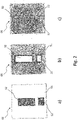
- Fig. 1
- ein Ausführungsbeispiel eines Reflektors einer Fahrzeugleuchte, dessen aus transparentem Werkstoff hergestellter Reflektorkörper an seiner zum Teil mit einer reflektierenden Beschichtung versehenen, eine eine oder mehrere Lichtfunktionen der Fahrzeugleuchte verwirklichende Leuchtfläche bildenden Reflektoroberfläche das Licht mindestens einer von einem ersten Leuchtmittel umfassten ersten Lichtquelle umlenkt, und an einem frei von der reflektierenden Beschichtung ausgeführten verbleibenden Teil seiner Reflektoroberfläche das Licht mindestens einer von einem zweiten Leuchtmittel umfassten zweiten Lichtquelle hindurchtreten lässt, in einer perspektivischen Ansicht.
- Fig. 2
- drei verschiedene Lichtsignaturen der vermittels der durch die Reflektoroberfläche des Reflektors aus
Fig. 1 gebildeten Leuchtfläche verwirklichten Lichtfunktionen bei Betrieb:- der zweiten Lichtquelle(n) in
Fig. 2 a) , - der ersten Lichtquelle(n) in
Fig. 2 b) , und - der ersten und der zweiten Lichtquellen in
Fig. 2 c) in einer Draufsicht auf die Reflektoroberfläche.
- der zweiten Lichtquelle(n) in
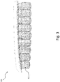
- Fig. 3
- ein Ausführungsbeispiel eines durch Bedampfen vollflächig mit einer reflektierenden Beschichtung versehenen Reflektors, dessen Reflektoroberfläche auf mehrere Reflektor-Schaufeln verteilt ist, in einer CAD-Darstellung mit Blick auf die Reflektor-Schaufeln von Fahrzeug hinten aus gesehen in einer Draufsicht.
- Fig. 4
- ein erstes Ausführungsbeispiel einer Aufteilung einer auf mehrere Reflektor-Schaufeln verteilten Reflektoroberfläche in einen mit einer reflektierenden Beschichtung ausgeführten Teil und in einen frei von einer reflektierenden Beschichtung ausgeführten verbleibenden Teil in Gestalt eines Schachbrettmusters in einer CAD-Darstellung mit Blick auf die Reflektor-Schaufeln von Fahrzeug hinten aus gesehen in einer Draufsicht.
- Fig. 5
- ein zweites Ausführungsbeispiel einer Aufteilung einer auf mehrere Reflektor-Schaufeln verteilten Reflektoroberfläche in einen mit einer reflektierenden Beschichtung ausgeführten Teil und in einen frei von einer reflektierenden Beschichtung ausgeführten verbleibenden Teil in Gestalt eines !-Musters in einer CAD-Darstellung mit Blick auf die Reflektor-Schaufeln von Fahrzeug hinten aus gesehen in einer Draufsicht.
- Fig. 6
- eine Detailansicht der Überlagerung des auf mehrere Reflektor-Schaufeln verteilten, mit einer reflektierenden Beschichtung ausgeführten Teils der Reflektoroberfläche und des frei von einer reflektierenden Beschichtung ausgeführten verbleibenden Teils der Reflektoroberfläche in Gestalt eines !-Musters gemäß der Aufteilung aus
Fig. 5 in einer perspektivischen Darstellung des Reflektors. - Fig. 7
- ein erstes Ausführungsbeispiel einer Aufteilung einer auf mehrere Reflektor-Schaufeln verteilten Reflektoroberfläche in einen mit einer reflektierenden Beschichtung ausgeführten Teil und in einen frei von einer reflektierenden Beschichtung ausgeführten verbleibenden Teil in Gestalt eines beispielsweise durch freilasern vollflächig von der zuvor auf die gesamte Reflektoroberfläche aufgetragenen reflektierenden Beschichtung befreiten odelo-Schriftzugs in einer CAD-Darstellung mit Blick auf die Reflektor-Schaufeln von Fahrzeug hinten aus gesehen in einer Draufsicht.
- Fig. 8
- ein zweites Ausführungsbeispiel einer Aufteilung einer auf mehrere Reflektor-Schaufeln verteilten Reflektoroberfläche in einen mit einer reflektierenden Beschichtung ausgeführten Teil und in einen frei von einer reflektierenden Beschichtung ausgeführten verbleibenden Teil in Gestalt eines Punktmusters aus großen, beispielsweise durch Freilasern von der zuvor auf die gesamte Reflektoroberfläche aufgetragenen reflektierenden Beschichtung befreiten Punkten zusammengesetzten odelo-Schriftzugs in einer CAD-Darstellung mit Blick auf die Reflektor-Schaufeln von Fahrzeug hinten aus gesehen in einer Draufsicht.
- Fig. 9
- ein drittes Ausführungsbeispiel einer Aufteilung einer auf mehrere Reflektor-Schaufeln verteilten Reflektoroberfläche in einen mit einer reflektierenden Beschichtung ausgeführten Teil und in einen frei von einer reflektierenden Beschichtung ausgeführten verbleibenden Teil in Gestalt eines Punktmusters aus mittelgroßen, beispielsweise durch Freilasern von der zuvor auf die gesamte Reflektoroberfläche aufgetragenen reflektierenden Beschichtung befreiten Punkten zusammengesetzten odelo-Schriftzugs in einer CAD-Darstellung mit Blick auf die Reflektor-Schaufeln von Fahrzeug hinten aus gesehen in einer Draufsicht.
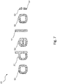
- Fig. 10
- ein viertes Ausführungsbeispiel einer Aufteilung einer auf mehrere Reflektor-Schaufeln verteilten Reflektoroberfläche in einen mit einer reflektierenden Beschichtung ausgeführten Teil und in einen frei von einer reflektierenden Beschichtung ausgeführten verbleibenden Teil in Gestalt eines Punktmusters aus kleinen, beispielsweise durch Freilasern von der zuvor auf die gesamte Reflektoroberfläche aufgetragenen reflektierenden Beschichtung befreiten Punkten zusammengesetzten odelo-Schriftzugs in einer CAD-Darstellung mit Blick auf die Reflektor-Schaufeln von Fahrzeug hinten aus gesehen in einer Draufsicht.
- Fig. 11
- eine Detailansicht der Überlagerung des auf mehrere Reflektor-Schaufeln verteilten, mit einer reflektierenden Beschichtung ausgeführten Teils der Reflektoroberfläche und des frei von einer reflektierenden Beschichtung ausgeführten verbleibenden Teils der Reflektoroberfläche in Gestalt eines odelo-Schriftzugs gemäß der Aufteilung aus
Fig. 8 in einer perspektivischen Darstellung des Reflektors. - Fig.
- 12eine Fahrzeugleuchte mit dem Reflektor aus
Fig. 1 in einem Längsschnitt.
- 1
- an exemplary embodiment of a reflector of a vehicle lamp, whose reflector body made of transparent material, on its reflector surface, which is partially provided with a reflective coating and forms a luminous surface that implements one or more light functions of the vehicle lamp, deflects the light of at least one first light source comprised of a first illuminant, and on one allows the light of at least one second light source, comprised of a second light source, to pass through the remaining part of its reflector surface, which is free of the reflective coating, in a perspective view.
- 2
- three different light signatures by means of the through the reflector surface of the reflector
1 light functions realized during operation:- the second light source(s) in
Fig. 2 a) , - the first light source(s) in
Fig. 2 b) , and - the first and the second light sources in
Fig. 2 c) in a plan view of the reflector surface.
- the second light source(s) in
- 3
- an embodiment of a reflector provided with a reflective coating over the entire surface by vapor deposition, the reflector surface of which is distributed over several reflector blades, in a CAD representation with a view of the reflector blades seen from the rear of the vehicle in a plan view.
- 4
- a first embodiment of a division of a reflector surface distributed over several reflector blades into a part with a reflective coating and a remaining part that is free of a reflective coating in the form of a checkerboard pattern in a CAD representation with a view of the reflector blades of the vehicle seen from behind in a plan view.
- figure 5
- a second embodiment of a division of a reflector surface distributed over several reflector blades into a part with a reflective coating and a remaining part without a reflective coating in the form of a ! pattern in a CAD representation with a view of the reflector blades Seen from the rear of the vehicle in a plan view.
- 6
- 1 shows a detailed view of the superimposition of the part of the reflector surface, which is distributed over several reflector blades and has a reflective coating, and the remaining part of the reflector surface, which is free of a reflective coating, in the form of a ! pattern according to the division
figure 5 in a perspective view of the reflector. - 7
- a first exemplary embodiment of a division of a reflector surface distributed over a plurality of reflector blades into a part with a reflective coating and a remaining part free of a reflective coating in the form of a reflective coating previously applied to the entire reflector surface over the entire surface, for example by free lasering odelo lettering in a CAD representation with a view of the reflector blades seen from the rear of the vehicle in a plan view.
- 8
- a second embodiment of a division of a reflector surface distributed over several reflector blades into a part with a reflective coating and a remaining part free of a reflective coating in the form of a dot pattern of large dots, for example by free lasering from the one previously applied to the entire reflector surface reflective coating liberated dots composite odelo lettering in a CAD representation with a view of the reflector blades seen from the rear of the vehicle in a plan view.
- 9
- a third embodiment of a division of a reflector surface distributed over several reflector blades into a part with a reflective coating and a remaining part free of a reflective coating in the form of a dot pattern of medium-sized, for example by lasering free of the previously applied to the entire reflector surface reflective coating liberated dots composite odelo lettering in a CAD representation with a view of the reflector blades seen from the rear of the vehicle in a plan view.
- 10
- a fourth embodiment of a division of a reflector surface distributed over several reflector blades into a part with a reflective coating and a remaining part free of a reflective coating in the form of a dot pattern of small dots, for example by free lasering from the one previously applied to the entire reflector surface reflective Coating of liberated points of composite odelo lettering in a CAD representation with a view of the reflector blades seen from the vehicle rear in a plan view.
- 11
- shows a detailed view of the superimposition of the part of the reflector surface that is distributed over several reflector blades and has a reflective coating and the remaining part of the reflector surface that is free of a reflective coating in the form of an odelo lettering according to the division
8 in a perspective view of the reflector. - figure
- 12a vehicle lamp with the reflector
1 in a longitudinal section.
Eine in
In dem Leuchteninnenraum 04 ist ein Reflektor 05 wenigstens zum Teil beherbergt. Der Reflektor 05 bildet und/oder umfasst zumindest einen Teil einer Leuchtfläche zur Verwirklichung wenigstens einer Lichtfunktion der Fahrzeugleuchte 01, oder er ist von einer Leuchtfläche zur Verwirklichung einer Lichtfunktion der der Fahrzeugleuchte 01 umfasst.A
Der Reflektor 05 umfasst einen zumindest für Licht in einem zumindest für das menschliche Auge sichtbaren Teil des elektromagnetischen Spektrums transparenten Reflektorkörper 50 mit einer vorzugsweise sowohl der Lichtscheibe 03, als auch einer zu reflektierendes Licht abstrahlenden ersten Lichtquelle 06 zumindest zum Teil zugewandten Reflektoroberfläche 51.The
Die Reflektoroberfläche 51 ist zum Teil mit einer reflektierenden Beschichtung versehen. Ein verbleibender Teil 52 der Reflektoroberfläche 51 ist frei von der reflektierenden Beschichtung ausgeführt.The
Die bereits erwähnte erste Lichtquelle 06 strahlt ihr Licht in den Reflektor 05 ein, indem sie ihr Licht auf die von der Leuchtfläche für beispielsweise zwei Lichtfunktionen umfassten Reflektoroberfläche 51 strahlt. In
Eine zweite Lichtquelle 07 strahlt ihr Licht von einer der Reflektoroberfläche 51 abgewandten Seite durch den Reflektorkörper 50 und durch den beispielsweise in mehrere von der reflektierenden Beschichtung freie Bereiche gegliederten verbleibenden Teil 52 der Reflektoroberfläche 51 beispielsweise in Richtung Lichtscheibe 03 hindurch. In
Der Reflektor 05 lenkt das Licht der ersten Lichtquelle 06 bevorzugt in Richtung Lichtscheibe 03 um. Die zweite Lichtquelle 07 strahlt ihr Licht durch den Reflektorkörper 50 und durch den beispielsweise in mehrere von der reflektierenden Beschichtung freie Bereiche gegliederten verbleibenden Teil 52 der Reflektoroberfläche 51 hindurch ebenfalls bevorzugt in Richtung Lichtscheibe 03.The
Wie in
Alternativ oder zusätzlich kann wie ebenso in
Die erste Lichtquelle 06 und/oder die zweite Lichtquelle 07 können vorteilhaft als Halbleiterlichtquellen ausgeführt sein. Halbleiterlichtquellen, wie etwa LEDs (anorganische Leuchtdioden) und/oder OLEDs (organische Leuchtdioden) weisen eine sehr kurze, kaum messbare Aktivierungszeit vom Beginn einer Strombeaufschlagung bis zur Abstrahlung von Licht auf. Dabei erfolgt die Lichtabstrahlung im Gegensatz zu einer Glühlampe quasi vom ersten Augenblick der Strombeaufschlagung an mit voller, der Stromstärke proportionaler Leuchtstärke. Darüber hinaus weisen sie einen hohen Wirkungsgrad bei der Umwandlung von elektrischem Strom in für das menschliche Auge sichtbares Licht auf. Ferner weisen insbesondere LEDs eine sehr hohe Lebensdauer bei Einsatz in Fahrzeugleuchten auf.The
Eine vorteilhafte Weiterbildung sieht vor, dass der frei von der reflektierenden Beschichtung ausgeführte verbleibende Teil 52 der Reflektoroberfläche 51 zunächst mit der reflektierenden Beschichtung versehen und anschließend durch freilasern von der reflektierenden Beschichtung wieder befreit ist.An advantageous development provides that the remaining
Beispielsweise ist die Reflektoroberfläche 51 zunächst vollflächig mit einer reflektierenden Beschichtung versehen, die im frei von der reflektierenden Beschichtung ausgeführten verbleibenden Teil 52 der Reflektoroberfläche 51 durch Freilasern teilweise wieder entfernt ist.For example, the
Die zweite Lichtquelle 07 strahlt ihr Licht hierbei durch die von der reflektierenden Beschichtung freigelaserten Bereiche der Reflektoroberfläche 51 hindurch.The second
Gemäß den voranstehend beschriebenen Ausgestaltungen ist bevorzugt vorgesehen, dass eine erste Lichtquelle 06 ihr Licht in einen die Leuchtfläche für eine oder mehrere, beispielsweise für zwei Lichtfunktionen bildenden beziehungsweise von der Leuchtfläche für eine oder mehrere, bevorzugt für zwei Lichtfunktionen umfassten Reflektor 05 einstrahlt, wobei eine zweite Lichtquelle 07 ihr Licht durch von der reflektierenden Beschichtung freigelaserte Bereiche hindurchstrahlt.According to the configurations described above, it is preferably provided that a
Dies erlaubt durch freie Gestaltung der freigelaserten Bereiche die Darstellung beispelsweise von Logos/Warnhinweisen innerhalb der durch die Reflektoroberfläche 51 gebildeten Leuchtfläche, indem beispielsweise nur eine Lichtfunktion aktiviert wird.By freely designing the lasered areas, this allows the display of logos/warning notices, for example, within the luminous area formed by the
Werden beide Lichtfunktionen mit gleicher Lichtfarbe zeitgleich erfüllt, leuchtet die gesamte, den Reflektor 05 umfassende und/oder von diesem umfasste Leuchtfläche in der Lichtfarbe auf.If both light functions are fulfilled at the same time with the same light color, the entire luminous surface surrounding and/or surrounded by the
Wenn keine Lichtfunktion aktiviert wird, kann durch entsprechend feine Strukturierung ein im ausgeschalteten Zustand sichtbares Logo auf dem Reflektor 05 dargestellt werden.If no light function is activated, a logo that is visible in the switched-off state can be displayed on the
Weisen zwei durch die erste Lichtquelle 06 und durch die zweite Lichtquelle 07 verwirklichten Lichtfunktionen unterschiedliche Lichtfarben auf, so können Logos und/oder Warnhinweise innerhalb der durch die Reflektoroberfläche 51 gebildeten Leuchtfläche zusätzlich auch bei gleichzeitiger Aktivierung beider Lichtfunktionen dargestellt werden.If two light functions implemented by the
Vorteile gegenüber dem Stand der Technik sind unter Anderem eine Einsparung von Bauraum und Gewicht. Darüber hinaus gehende Vorteile sind die Verwirklichung mindestens zweier Lichtfunktionen beliebiger Lichtfarbe innerhalb ein und derselben Leuchtfläche. Ein zusätzlicher Vorteil ist die Schaffung einer Möglichkeit zur Darstellung von Symbolen und Zeichen, beispielsweise von Warnhinweisen innerhalb einer Leuchtfläche.Advantages over the prior art include a saving in installation space and weight. Additional advantages are the implementation of at least two light functions of any light color within one and the same luminous area. An additional advantage is the creation of a possibility for displaying symbols and characters, for example warnings within a luminous area.
Die neuartige Fahrzeugleuchte 01 ermöglicht eine Gestaltung neuer Lichtfunktionalitäten beispielsweise durch einen partiellen Laserabtrag von beispielsweise bedampften Oberflächen sowie alternativ oder zusätzlich eine flexible Anpassung von Lichtsignaturen durch eine dezidierte Beleuchtung von Bauteilen.The new type of
Damit können beispielsweise auch Klick-Klack-Effekte bei Lichtfunktionen erzeugt werden, beispielsweise indem zwischen Schlusslichtfunktion und Bremslichtfunktion durch hin- und herschalten beispielsweise zwischen den in
Werden die einzelnen Bereiche des frei von der reflektierenden Beschichtung ausgeführten verbleibenden Teils 52 der Reflektoroberfläche 51 oder allgemein auf einem optischen Element aus einem transparenten Körper mit einer teilweise mit einer reflektierenden Beschichtung versehenen Oberfläche ausreichend klein gewählt, ist es für den Betrachter aus entsprechender Entfernung nicht mehr erkennbar, dass auf dem Reflektor lückenhafte Sichtsignaturen dargestellt werden. Dies ist insbesondere bei einer Betrachtung im so genannten Fernfeld ab vorzugsweise 10 m Abstand zur Lichtfunktion der Fall. Daher kann auch mit derartigen Ausgestaltungen eine homogene Lichtsignatur verwirklicht werden.If the individual areas of the remaining
Zudem ist es möglich die beispielsweise durch mehrere LEDs verwirklichten ersten und zweiten Lichtquellen 06, 07 der jeweils anderen Lichtfunktion mit geringer Intensität mitleuchten zu lassen, um die Lücken in der Lichtsignatur unauffälliger zu gestalten. Dies ist insbesondere für eine Betrachtung im Nahfeld aus einem Abstand von weniger als 10 m vorteilhaft. Im oben genannten Beispiel von zwei unterschiedlichen Lichtsignaturen für vorzugsweise die gleiche Lichtfunktion werden dann zur Darstellung beide Bereiche aktiviert, so dass sich die Leuchtdichten der transparenten und der verspiegelten Bereiche einander annähern.In addition, it is possible to let the first and second
Es besteht ferner die Möglichkeit, zwei Lichtfunktionen über freigelaserte Bereiche auf einem Reflektor 05 zu kombinieren und damit reflektierende und freigelaserte Flächen jeweils so zu gestalten, dass die Abstrahlcharakteristik des Lichts in beiden Fällen weitestgehend gleich ist. Damit lassen sich Warnsymbole, Logos und/oder Designelemente gestalten, die wahlweise mit Positiv- oder Negativkontrast dargestellt werden, aber auch durch eine abgestimmte Beleuchtung beider Bereiche optisch komplett homogen erscheinen können, wie etwa in
Wichtig ist hervorzuheben, dass ein derartiges Ergebnis mit einer schablonierten Bedampfung nicht zu erreichen ist, weil ansonsten bei der so genannten Schatten-Maske stets Verbindungsstege angebracht sein müssten, um die abzuschattenden Bereiche auf der Maske mechanisch miteinander zu verbinden. Auch wäre eine derartige Maske mechanisch nicht mehr ausreichend stabil, da sie aus sehr vielen kleinen Elementen bestünde, die nur durch dünne Verbindungsstege zusammengehalten werden. Dies ist für einen Massenprozess in der Herstellung nicht zielführend.It is important to emphasize that such a result cannot be achieved with stenciled vaporization, because otherwise connecting webs would always have to be attached to the so-called shadow mask in order to mechanically connect the areas on the mask to be shadowed with one another. A mask of this type would also no longer be sufficiently stable mechanically, since it would consist of a large number of small elements which are only held together by thin connecting webs. This is not expedient for a mass production process.
Durch ein Freilasern des beispielsweise in mehrere von der reflektierenden Beschichtung freie Bereiche gegliederten verbleibenden Teils 52 der Reflektoroberfläche 51 ist außerdem ein Verstecken von Logos, Schriftzügen, etc. auf dem beispielsweise als Reflektor ausgeführten optischen Element möglich. Die im Folgenden beschriebene Möglichkeit zeigt eine über Reflexion an einem metallisierten Reflektor umgesetzte Lösung. Analog ist auch eine Umsetzung in einer Optikscheibe möglich, bei der dann freigelaserte Bereiche Licht hindurch lassen und somit leuchten und nicht freigelaserte Bereiche das Licht blockieren und somit nicht leuchten. Bei der Umsetzung in einer Optikscheibe ist auch die Umsetzung mittels einer hinterspritzten bedruckten Folie möglich. Bei der Umsetzung als Reflektor ist dagegen das Hinterspritzen einer bedruckten Folie nachteilig, weil eine gerichtet metallisch reflektierende Fläche nur schwer als Druckmuster erzeugt werden kann. Die weitere Beschreibung erfolgt am Beispiel einer Lichtfunktion mit Reflektor 05.By lasering the remaining
Auf einem solchen Reflektor 05 sollen Logos und/oder Gestaltungselemente platziert werden, die im ausgeschalteten Zustand der Lichtfunktion sichtbar, im eingeschalteten Zustand jedoch nicht sichtbar sind. Dazu wird beispielsweise das Logo oder Designelement auf dem Reflektor nicht vollflächig freigelasert, sondern nur als feines Punktmuster 53, wie in
Gemäß dieser vorteilhaften Ausgestaltung ist der verbleibende Teil 52 der Reflektoroberfläche 51 als Punktmuster 53 ausgeführt.According to this advantageous embodiment, the remaining
Mit herkömmlichen Verfahren ist ein solches Muster aus kleinen nichtmetallisierten Bereichen nicht zu erzeugen. Im ausgeschalteten Zustand der Lichtfunktion ist das Punktmuster 53 als Logo und/oder Designelement auf dem Reflektor 05 sichtbar. Die kleinen nicht-reflektierenden Bereiche werden jedoch bei eingeschalteter Beleuchtung vollständig überstrahlt, sodass mindestens im Fernfeld visuell nur noch eine homogen leuchtende Fläche wahrnehmbar ist.Such a pattern of small non-metallized areas cannot be produced with conventional methods. When the light function is switched off, the
Die Ausgestaltung kann beispielsweise so erfolgen, dass anstatt einzelner Prismen einzeln spiegelnde Bereiche verwendet werden. Das Ergebnis kann bei entsprechender Auslegung so gestaltet werden, dass die Lichtsignatur entsprechend ausgeführt ist. Ein Logo oder Designelement mit einer solchen Ausgestaltung kann bis zu einem gewissen Maximalabstand im Nahfeld auch im beleuchteten Zustand noch sichtbar sein.For example, the design can be such that instead of individual prisms, individually reflecting areas are used. With an appropriate design, the result can be designed in such a way that the light signature is executed accordingly. A logo or design element with such a design can still be visible up to a certain maximum distance in the near field even when illuminated.
Dieser Maximalabstand wird im beleuchteten Zustand geringer ausfallen als bei Umgebungslicht im unbeleuchteten Zustand, wenn anstelle der leuchtenden Auskoppelprismen nicht reflektierende, freigelaserte Punkte des Punktmusters 53 treten. Das Erscheinungsbild ist dann gegenüber einer Ausgestaltung mit leuchtenden Auskoppelprismen invertiert. Im beleuchteten Zustand werden die dann nichtleuchtenden Punkte des Punktmusters 53 von der leuchtenden umgebenden Fläche überstrahlt, sodass sie schon bei geringerem Betrachtungsabstand verschwinden.This maximum distance will turn out to be smaller in the illuminated state than in the case of ambient light in the unilluminated state if non-reflecting, lasered points of the
Insgesamt ist es mit dieser Ausgestaltung möglich, im beleuchteten Zustand eine noch homogenere Leuchtdichte zu erreichen als wenn die Umgebung des Logos und/oder Designelements vollflächig reflektierend gestaltet ist, wie in der zu Beginn des Abschnitts beschriebenen Möglichkeit. Somit wird die Sichtbarkeit von Schriftzügen und/oder Logos und/oder Designelementen im beleuchteten Zustand noch weiter verringert.Overall, with this configuration it is possible to achieve an even more homogeneous luminance in the illuminated state than if the area surrounding the logo and/or design element is designed to be reflective over the entire surface, as in the option described at the beginning of the section. Thus, the visibility of lettering and/or logos and/or design elements is reduced even further in the illuminated state.
Anzumerken ist auch noch die Möglichkeit, einen Mittelweg zwischen der Ausgestaltung mit leuchtenden Auskoppelprismen und der voranstehend beschriebenen Möglichkeit zu wählen. Hierbei ist der freigelaserte Flächenanteil im Bereich des Schriftzugs und/oder Logos und/oder Designelements nicht gleich dem freigelaserten Flächenanteil außerhalb des Schriftzugs und/oder Logos und/oder Designelements, jedoch werden auch dort Bereiche freigelasert, um ein insgesamt homogeneres Erscheinungsbild im beleuchteten Zustand zu erreichen, ohne die Sichtbarkeit des Schriftzugs und/oder Logos und/oder Designelements im ausgeschalteten Zustand zu sehr zu verringern.It should also be noted that there is also the possibility of choosing a middle ground between the design with luminous decoupling prisms and the possibility described above. The lasered area in the area of the lettering and/or logo and/or design element is not the same as the lasered area outside of the lettering and/or logo and/or design element, but areas are also lasered there in order to achieve a more homogeneous overall appearance when illuminated achieve without reducing the visibility of the lettering and/or logo and/or design elements too much when switched off.
Eine vorteilhafte Weiterbildung der Fahrzeugleuchte 01 sieht vor, dass zumindest eine Partie des Reflektorkörpers 50, durch welche Partie die zweite Lichtquelle 07 ihr Licht von der der Reflektoroberfläche 51 abgewandten Seite durch den Reflektorkörper 50 und durch den von der reflektierenden Beschichtung freien verbleibenden Teil 52 der Reflektoroberfläche 51 bevorzugt in Richtung Lichtscheibe 03 hindurch strahlt, mit die Lichtverteilung des von der zweiten Lichtquelle 07 durch die Partie hindurchgestrahlten Lichts beeinflussenden optisch wirksamen Strukturen versehen ist.An advantageous development of
Eine besonders vorteilhafte Weiterbildung sieht demnach vor, dass zumindest der frei von der reflektierenden Beschichtung ausgeführte, verbleibende Teil 52 der Reflektoroberfläche 51, beispielsweise die freigelaserten Bereiche einer zuvor vollflächig verspiegelten Reflektoroberfläche 51, auf einer im Strahlengang der zweiten Lichtquelle 07 liegenden und dieser zugewandten Seite mit die Lichtverteilung des von der zweiten Lichtquelle 07 hindurchgestrahlten Lichts beeinflussenden optisch wirksamen Strukturen versehen ist.A particularly advantageous development therefore provides that at least the remaining
Bei der der zweiten Lichtquelle 07 zugewandten Seite handelt es sich um diejenige, der Reflektoroberfläche 51 abgewandte Seite, von welcher aus die zweite Lichtquelle 07 ihr Licht durch den Reflektorkörper 50 und durch die von der reflektierenden Beschichtung 51 freien Bereiche der Reflektoroberfläche 51 hindurch beispielsweise in Richtung Lichtscheibe 03 strahlt.The side facing the second
Der Leuchtflächenbereich, durch den die zweite Lichtquelle 07 ihr Licht hindurchstrahlt, kann demnach zu Zwecken einer Einflussnahme auf die Lichtverteilung von den Leuchtflächenbereich passierendem Licht optisch strukturiert sein.The luminous surface area through which the second
Eine derart unterschiedliche Beeinflussung der Lichtverteilung des von der ersten Lichtquelle 06 abgestrahlten Lichts und der Lichtverteilung des von der zweiten Lichtquelle 07 abgestrahlten Lichts ist in
Die beispielsweise als optische Strukturierung ausgeführten und/oder eine solche umfassenden optisch wirksamen Strukturen können vorder- und/oder rückseitig des Reflektorkörpers 50 in Bezug auf dessen Durchstrahlung mit Licht der zweiten Lichtquelle 07 angeordnet sein.The optically active structures that are designed, for example, as optical structuring and/or include such structures can be arranged on the front and/or rear of the
Diese vorteilhafte Weiterbildung der Erfindung sieht beispielsweise ein Freilasern von Teilen einer zuvor verspiegelten, eine Reflektoroberfläche bildenden Oberfläche eines einen Reflektorkörper bildenden, zumindest in einem für das menschliche Auge sichtbaren Teil des elektromagnetischen Spektrums transparenten Optikelements vor, verbunden mit dem Ziel, die verspiegelt verbleibende Teil-Oberfläche des Optikelements als Reflektor für eine durch eine erste Lichtquelle verwirklichte Lichtfunktion vorzusehen, die ihr Licht in den Reflektor einstrahlt, und die Partie des Optikelements mit der von der Verspiegelung befreiten Teil-Oberfläche als Vorsatz-Optikelement für eine durch eine zweite Lichtquelle verwirklichte Lichtfunktion vorzusehen, die ihr Licht durch das Optikelement hindurchstrahlt.This advantageous further development of the invention provides, for example, for parts of a previously mirrored surface forming a reflector surface to be lasered free of an optical element which forms a reflector body and is transparent at least in a part of the electromagnetic spectrum that is visible to the human eye, with the aim of removing the remaining part Provide the surface of the optical element as a reflector for a light function realized by a first light source, which radiates its light into the reflector, and to provide the part of the optical element with the partial surface freed from the mirror coating as an attachment optical element for a light function realized by a second light source , which transmits its light through the optical element.
Beispielsweise können die beispielsweise als optische Strukturierung ausgeführten und/oder eine solche umfassenden optisch wirksamen Strukturen Linsengeometrien und/oder-felder umfassen.For example, the optically effective structures designed and/or comprising such an optical structuring can comprise lens geometries and/or fields.
Vorteilhaft können zumindest im Bereich der von der Verspiegelung verschonten oder beispielsweise befreiten Teil-Oberfläche auf der der zweiten Lichtquelle 07 zugewandten Seite des ein Optikelement bildenden Reflektors 05 optisch wirksame Strukturen, wie etwa Linsengeometrien oder dergleichen aufgebracht sein. Hierdurch weisen die erste und die zweite Lichtfunktion unterschiedliche Lichtverteilungen auf.Optically active structures, such as lens geometries or the like, can advantageously be applied at least in the area of the partial surface that is spared or, for example, freed from the mirror coating on the side of the
Damit ergänzt die vorteilhafte Weiterbildung der Erfindung die voranstehend beschriebenen Ausgestaltungen um den Aspekt, dass die durchstrahlende Lichtfunktion beispielsweise durch makroskopische Optikelemente, wie etwa Linsen oder durch Mikrolinsenarrays gebildete optisch wirksamen Strukturen passiert, welche eine Anpassung der Lichtverteilung der durchstrahlenden Lichtfunktion bewirkt.The advantageous development of the invention thus supplements the configurations described above with the aspect that the light function passing through it passes through macroscopic optical elements such as lenses or optically effective structures formed by microlens arrays, which causes an adaptation of the light distribution of the light function passing through.
Bei der durchstrahlenden Lichtfunktion handelt es sich dabei um die durch das von der zweiten Lichtquelle 07 abgestrahlte Licht verwirklichte Lichtfunktion.The light function that shines through is the light function that is implemented by the light emitted by the second
Das in
Durch entsprechend angepasste Optiken auf dem transparent ausgeführten Reflektorsubstrat können entsprechend für die Darstellung von BRL-Funktionen engere Lichtverteilungen und für SL entsprechend der spiegelnden Bereiche auf dem Reflektorelement weitere Abstrahlbereiche verwirklicht werden. Es ist somit eine Entkopplung der Bereiche und Funktionen möglich.With appropriately adapted optics on the transparent reflector substrate, narrower light distributions can be realized for the representation of BRL functions and further emission areas can be realized for SL according to the reflective areas on the reflector element. It is thus possible to decouple the areas and functions.
So ist beispielsweise denkbar, einen Reflektor 05 mit einer partiell freigelaserten Reflektoroberfläche 51 vorzusehen, wobei ein beispielsweise in mehrere Bereiche untergliederter verbleibender Teil 52 der Reflektoroberfläche 51, der frei von der reflektierenden Beschichtung ausgeführt ist, der von hinten von einer oder mehreren zweiten Lichtquellen 07 durchstrahlt wird. Der in mehrere Bereiche untergliederter verbleibender Teil 52 der Reflektoroberfläche 51, der frei von der reflektierenden Beschichtung ausgeführt ist, kann beispielsweise wie ein in
Jedes von der reflektierenden Beschichtung freigelaserte Feld des Schachbrettmusters verfügt über eine eigene, im Strahlengang des von der zweiten Lichtquelle 07 durch den Reflektorkörper 50 und den freigelaserten, verbleibenden Teil 52 der Reflektoroberfläche 51 hindurchgestrahlten Lichts angeordnete, transparente Optik. Hierbei kann eine facettierte Optik gebildet werden.Each field of the checkerboard pattern lasered free of the reflective coating has its own transparent lens arranged in the beam path of the light emitted from the second
Das Licht wird von den transparenten Optiken auf dem Reflektor 05 entsprechend einer vorgegebenen Wunschvorstellung geformt; Das Reflektorsubstrat, aus dem der Reflektorkörper 50 hergestellt ist, ist transparent. Der Reflektor 05 wurde an seiner Reflektoroberfläche 51 zunächst vollflächig bedampft. Der Reflektor 05 wurde an seiner Reflektoroberfläche 51 anschließend partiell freigelasert, sodass die beispielsweise Aluminium umfassende reflektierende Beschichtung in diesen Bereichen verschwunden ist und das transparente Reflektorsubstrat wieder zum Vorschein tritt. Hierdurch wird nachträglich nach dem vollflächigen Bedampfen der frei von der reflektierenden Beschichtung ausgeführte verbleibende Teil 52 der Reflektoroberfläche 51 gebildet.The light is shaped by the transparent optics on the
Zur Herstellung eines partiell freigelaserten Reflektors 05 kann beispielsweise die Reflektoroberfläche 51 eines transparenten Reflektorkörpers 50 zunächst vollflächig bedampft werden. Nach der Bedampfung kann der Reflektor 05 im genannten Bereich seiner Reflektoroberfläche 51 partiell freigelasert werden.To produce a partially lasered
Eine vorteilhafte Weiterbildung der Erfindung sieht ein Freilasern und Kodieren von Oberflächen vor, beispielsweise das Freilasern von Oberflächen zur Erzeugung von mindestens zwei Lichtfunktionalitäten in einem optisch-strukturierten Leuchtflächenbereich.An advantageous development of the invention provides for free lasering and coding of surfaces, for example free lasering of surfaces to generate at least two light functionalities in an optically structured luminous surface area.
Hierbei ist der frei von der reflektierenden Beschichtung ausgeführte verbleibende Teil 52 der Reflektoroberfläche 51 beispielsweise in Gestalt seines Umrisses und/oder Form und/oder Geometrie gemäß einer Kodierung einer Lichtsignatur ausgebildet.In this case, the remaining
Wichtig ist hervorzuheben, dass die Fahrzeugleuchte 01 wenigstens zwei jeweils mindestens eine Lichtquelle 06, 07 umfassende Leuchtmittel 60, 70 umfassen kann, einem ersten Leuchtmittel 60 mit mindestens der ersten Lichtquelle 06 zur Erfüllung wenigstens einer ersten Lichtfunktion der Fahrzeugleuchte 01 und einem zweiten Leuchtmittel mit mindestens der zweiten Lichtquelle 07 zur Erfüllung wenigstens einer zweiten Lichtfunktion der Fahrzeugleuchte 01.It is important to emphasize that the
Vorteilhaft sind bei der Fahrzeugleuchte 01 gleich welcher voranstehend beschriebenen Ausgestaltung die mindestens eine erste Lichtquelle 06 und die mindestens eine zweite Lichtquelle 07 unabhängig voneinander betreibbar.In
Bei einem gemeinsamen Betrieb können sie einer Erfüllung der selben Lichtfunktion beitragen.When operated together, they can contribute to fulfilling the same lighting function.
Alternativ können sie bei einem gemeinsamen Betrieb einer Erfüllung unterschiedlicher Lichtfunktion beitragen.Alternatively, when operated together, they can contribute to the fulfillment of different light functions.
Es ist ersichtlich, dass die Erfindung verwirklicht sein kann durch Freilasern von Teilen einer reflektierenden Beschichtung einer Reflektoroberfläche 51 mit dem Ziel, zusätzliche Lichteffekte innerhalb einer für eine oder für zwei Lichtfunktionen gleicher oder unterschiedlicher Lichtfarbe zur Verfügung stehenden, die reflektierende Beschichtung umfassenden Leuchtfläche zu verwirklichen.It can be seen that the invention can be implemented by lasering parts of a reflective coating of a
Ebenfalls wichtig ist hervorzuheben, dass die Erfindung den Stand der Technik dahingehend erweitert, dass eine erste Lichtquelle ihr Licht in einen die Leuchtfläche für zwei Lichtfunktionen bildenden Reflektor einstrahlt, und dass eine zweite Lichtquelle ihr Licht durch von der reflektierenden Beschichtung freigelaserte Bereiche hindurchstrahlt. Dies erlaubt durch freie Gestaltung der freigelaserten Bereiche die Darstellung beispielsweise von Logos und/oder Warnhinweisen. Die Erfindung erweitert den Gestaltungsfreiraum von Leuchten und erzeugt neue Möglichkeiten insbesondere bei der Gestaltung von Lichtsignaturen und der Kodierung von Lichtsignaturen.It is also important to emphasize that the invention expands the prior art in that a first light source radiates its light into a reflector forming the luminous surface for two light functions, and that a second light source transmits its light through areas lasered free of the reflective coating. This allows the display of logos and/or warnings, for example, through the free design of the lasered areas. The invention expands the design freedom of lights and creates new possibilities, particularly in the design of light signatures and the coding of light signatures.
Die Erfindung erweitert erheblich die Gestaltungsmöglichkeiten von optischen Systemen.The invention significantly expands the design options for optical systems.
Die Fahrzeugleuchte 01 kann alternativ oder zusätzlich einzelne oder eine Kombination mehrerer einleitend in Verbindung mit dem Stand der Technik und/oder in einem oder mehreren der zum Stand der Technik erwähnten Dokumente und/oder in der voranstehenden Beschreibung und/oder in den nachfolgenden Ansprüchen erwähnte Merkmale aufweisen.The
Die Erfindung ist nicht durch die Beschreibung anhand der Ausführungsbeispiele beschränkt. Vielmehr umfasst die Erfindung jedes neue Merkmal sowie jede Kombination von Merkmalen, was insbesondere jede Kombination von Merkmalen in den Ansprüchen beinhaltet, auch wenn dieses Merkmal oder diese Kombination selbst nicht explizit in den Ansprüchen oder Ausführungsbeispielen angegeben ist.The invention is not limited by the description based on the exemplary embodiments. Rather, the invention encompasses every new feature and every combination of features, which in particular includes every combination of features in the claims, even if this feature or this combination itself is not explicitly specified in the claims or exemplary embodiments.
Die Erfindung ist insbesondere im Bereich der Herstellung von Fahrzeugleuchten, insbesondere Kraftfahrzeugleuchten gewerblich anwendbar.The invention can be used commercially in particular in the field of manufacturing vehicle lights, in particular motor vehicle lights.
Die Erfindung wurde unter Bezugnahme auf bevorzugte Ausführungsformen beschrieben. Es ist jedoch für einen Fachmann vorstellbar, dass Abwandlungen oder Änderungen der Erfindung gemacht werden können, ohne dabei den Schutzbereich der nachstehenden Ansprüche zu verlassen.The invention has been described with reference to preferred embodiments. However, it will be apparent to a person skilled in the art that modifications or variations can be made to the invention without departing from the scope of the following claims.
- 0101
- Fahrzeugleuchtevehicle light
- 0202
- Leuchtengehäuselamp housing
- 0303
- Lichtscheibelens
- 0404
- LeuchteninnenraumLuminaire interior
- 0505
- Reflektorreflector
- 0606
- erste Lichtquellefirst light source
- 0707
- zweite Lichtquellesecond light source
- 5050
- Reflektorkörperreflector body
- 5151
- Reflektoroberflächereflector surface
- 5252
- verbleibender Teil (der Reflektoroberfläche 51)remaining part (of the reflector surface 51)
- 5353
- PunktmusterDot pattern
- 6060
- erstes Leuchtmittelfirst illuminant
- 7070
- zweites Leuchtmittelsecond illuminant
Claims (11)
Priority Applications (1)
| Application Number | Priority Date | Filing Date | Title |
|---|---|---|---|
| EP21166510.4A EP4067732A1 (en) | 2021-04-01 | 2021-04-01 | Vehicle light with a luminous surface comprising a reflector surface |
Applications Claiming Priority (1)
| Application Number | Priority Date | Filing Date | Title |
|---|---|---|---|
| EP21166510.4A EP4067732A1 (en) | 2021-04-01 | 2021-04-01 | Vehicle light with a luminous surface comprising a reflector surface |
Publications (1)
| Publication Number | Publication Date |
|---|---|
| EP4067732A1 true EP4067732A1 (en) | 2022-10-05 |
Family
ID=75362380
Family Applications (1)
| Application Number | Title | Priority Date | Filing Date |
|---|---|---|---|
| EP21166510.4A Withdrawn EP4067732A1 (en) | 2021-04-01 | 2021-04-01 | Vehicle light with a luminous surface comprising a reflector surface |
Country Status (1)
| Country | Link |
|---|---|
| EP (1) | EP4067732A1 (en) |
Cited By (2)
| Publication number | Priority date | Publication date | Assignee | Title |
|---|---|---|---|---|
| WO2024184205A1 (en) * | 2023-03-06 | 2024-09-12 | Audi Ag | Illuminating device for the interior of a motor vehicle, and motor vehicle |
| WO2024199635A1 (en) * | 2023-03-28 | 2024-10-03 | Hella Autotechnik Nova S.R.O. | Reflector, low beam module and automobile headlight comprising the reflector and process of modification of working surface for the reflector |
Citations (10)
| Publication number | Priority date | Publication date | Assignee | Title |
|---|---|---|---|---|
| DE10139812A1 (en) * | 2001-08-14 | 2003-02-27 | Hella Kg Hueck & Co | Interior/courtesy light for motor vehicles has two luminous devices emitting light with different spectral distribution and a reflector for bundling the light from these luminous devices. |
| DE102006029412A1 (en) * | 2006-06-27 | 2008-01-03 | Automotive Lighting Reutlingen Gmbh | Motor vehicle e.g. car, light e.g. headlight or tail light, has front and rear illumination units partially arranged one behind other in light emitting direction, where each illumination unit includes light sources and reflectors |
| DE102008057538A1 (en) * | 2008-11-08 | 2009-07-09 | Daimler Ag | Vehicle light e.g. head light, has light source with inferior priority producing light that is injected into chamber and is superimposed on light produced by another light source having superior priority |
| DE102012007227A1 (en) * | 2012-04-07 | 2012-11-08 | Daimler Ag | Lighting device for vehicle lamp, has optical element having coupling point for coupling light beams emitted from light sources and decoupling point for coupling light beams |
| DE102011104055A1 (en) * | 2011-06-11 | 2012-12-13 | Volkswagen Aktiengesellschaft | Illumination device, particularly headlight or rear light for vehicle, comprises light source, which has multiple semiconductor light sources, where reflector has reflector body and reflection surface |
| DE102012100816A1 (en) * | 2012-02-01 | 2013-08-01 | Dr. Ing. H.C. F. Porsche Aktiengesellschaft | Vehicle lamp e.g. front lamp, for car, has light functional element serving as light guide and reflector, where light exit surface of portion of element acting as light guide is arranged above portion of element acting as reflector |
| US20160040847A1 (en) * | 2013-03-27 | 2016-02-11 | Koito Manufacturing Co., Ltd. | Vehicle lamp |
| DE102015216744A1 (en) * | 2015-09-02 | 2017-03-02 | Volkswagen Aktiengesellschaft | Vehicle lamp and method for providing a light function by means of a vehicle lamp |
| DE102017122207A1 (en) * | 2017-09-26 | 2019-03-28 | HELLA GmbH & Co. KGaA | Lighting device for a motor vehicle |
| DE102019117246A1 (en) | 2019-06-26 | 2020-12-31 | Odelo Gmbh | Light source with light booster function and vehicle light equipped with it |
-
2021
- 2021-04-01 EP EP21166510.4A patent/EP4067732A1/en not_active Withdrawn
Patent Citations (10)
| Publication number | Priority date | Publication date | Assignee | Title |
|---|---|---|---|---|
| DE10139812A1 (en) * | 2001-08-14 | 2003-02-27 | Hella Kg Hueck & Co | Interior/courtesy light for motor vehicles has two luminous devices emitting light with different spectral distribution and a reflector for bundling the light from these luminous devices. |
| DE102006029412A1 (en) * | 2006-06-27 | 2008-01-03 | Automotive Lighting Reutlingen Gmbh | Motor vehicle e.g. car, light e.g. headlight or tail light, has front and rear illumination units partially arranged one behind other in light emitting direction, where each illumination unit includes light sources and reflectors |
| DE102008057538A1 (en) * | 2008-11-08 | 2009-07-09 | Daimler Ag | Vehicle light e.g. head light, has light source with inferior priority producing light that is injected into chamber and is superimposed on light produced by another light source having superior priority |
| DE102011104055A1 (en) * | 2011-06-11 | 2012-12-13 | Volkswagen Aktiengesellschaft | Illumination device, particularly headlight or rear light for vehicle, comprises light source, which has multiple semiconductor light sources, where reflector has reflector body and reflection surface |
| DE102012100816A1 (en) * | 2012-02-01 | 2013-08-01 | Dr. Ing. H.C. F. Porsche Aktiengesellschaft | Vehicle lamp e.g. front lamp, for car, has light functional element serving as light guide and reflector, where light exit surface of portion of element acting as light guide is arranged above portion of element acting as reflector |
| DE102012007227A1 (en) * | 2012-04-07 | 2012-11-08 | Daimler Ag | Lighting device for vehicle lamp, has optical element having coupling point for coupling light beams emitted from light sources and decoupling point for coupling light beams |
| US20160040847A1 (en) * | 2013-03-27 | 2016-02-11 | Koito Manufacturing Co., Ltd. | Vehicle lamp |
| DE102015216744A1 (en) * | 2015-09-02 | 2017-03-02 | Volkswagen Aktiengesellschaft | Vehicle lamp and method for providing a light function by means of a vehicle lamp |
| DE102017122207A1 (en) * | 2017-09-26 | 2019-03-28 | HELLA GmbH & Co. KGaA | Lighting device for a motor vehicle |
| DE102019117246A1 (en) | 2019-06-26 | 2020-12-31 | Odelo Gmbh | Light source with light booster function and vehicle light equipped with it |
Cited By (2)
| Publication number | Priority date | Publication date | Assignee | Title |
|---|---|---|---|---|
| WO2024184205A1 (en) * | 2023-03-06 | 2024-09-12 | Audi Ag | Illuminating device for the interior of a motor vehicle, and motor vehicle |
| WO2024199635A1 (en) * | 2023-03-28 | 2024-10-03 | Hella Autotechnik Nova S.R.O. | Reflector, low beam module and automobile headlight comprising the reflector and process of modification of working surface for the reflector |
Similar Documents
| Publication | Publication Date | Title |
|---|---|---|
| WO2017042345A1 (en) | Illumination device for vehicles | |
| AT517394B1 (en) | Lighting device for a motor vehicle with luminescent elements | |
| DE102016205644B4 (en) | lighting device for a motor vehicle | |
| EP1757487A1 (en) | External rear mirror for vehicles | |
| DE202016106347U1 (en) | Illuminated badge for a vehicle | |
| DE102018208822B4 (en) | Lighting device for a vehicle and associated tailgate | |
| DE19538771B4 (en) | Exterior rearview mirror for vehicles, preferably for motor vehicles | |
| DE102018002721B4 (en) | Lighting device for a vehicle | |
| DE102018214790A1 (en) | Lighting device for a motor vehicle | |
| EP3344915B1 (en) | Vehicle light and method for providing a light function by means of a vehicle light | |
| EP4067732A1 (en) | Vehicle light with a luminous surface comprising a reflector surface | |
| DE102012211821B4 (en) | Luminaire unit for a motor vehicle, in which lamps are arranged in a housing shell with window portion | |
| EP4113001B1 (en) | Light module for a lighting device of a vehicle and method for reducing colour desaturation in a light module for a lighting device of a vehicle | |
| DE102011051152A1 (en) | Method for operating e.g. daytime running lamp in vehicle, involves operating portion of light sources with reduced operating current to amplify warning effect of flasher function by increased contrast between portions of light sources | |
| DE102015108804A1 (en) | vehicle component | |
| DE19838224C2 (en) | Front light assembly for motor vehicles | |
| DE10341572B4 (en) | Vehicle lamp with electroluminescent arrangement | |
| EP2146138A1 (en) | Lamp | |
| DE102020216061A1 (en) | VEHICLE LAMP AND VEHICLE | |
| DE102004046408A1 (en) | Translucent component for motor vehicle-head light, has lighting effect changing region and line for local influence of lighting characteristics of component, where region and line are manufactured by laser process | |
| EP1762777B1 (en) | Vehicule lighting unit | |
| DE102013016424B4 (en) | Lighting device for an automotive exterior lighting | |
| EP2020565A1 (en) | Lamp | |
| EP2565527A1 (en) | Signal lamp for motor vehicles | |
| DE102020116264A1 (en) | LIGHT GUIDE DEVICE, VEHICLE COMPONENTS AND VEHICLE |
Legal Events
| Date | Code | Title | Description |
|---|---|---|---|
| PUAI | Public reference made under article 153(3) epc to a published international application that has entered the european phase |
Free format text: ORIGINAL CODE: 0009012 |
|
| STAA | Information on the status of an ep patent application or granted ep patent |
Free format text: STATUS: THE APPLICATION HAS BEEN PUBLISHED |
|
| AK | Designated contracting states |
Kind code of ref document: A1 Designated state(s): AL AT BE BG CH CY CZ DE DK EE ES FI FR GB GR HR HU IE IS IT LI LT LU LV MC MK MT NL NO PL PT RO RS SE SI SK SM TR |
|
| STAA | Information on the status of an ep patent application or granted ep patent |
Free format text: STATUS: THE APPLICATION IS DEEMED TO BE WITHDRAWN |
|
| 18D | Application deemed to be withdrawn |
Effective date: 20230406 |