EP4067093A1 - Appareil de formation d'images avec support de convoyage amovible - Google Patents
Appareil de formation d'images avec support de convoyage amovible Download PDFInfo
- Publication number
- EP4067093A1 EP4067093A1 EP22162093.3A EP22162093A EP4067093A1 EP 4067093 A1 EP4067093 A1 EP 4067093A1 EP 22162093 A EP22162093 A EP 22162093A EP 4067093 A1 EP4067093 A1 EP 4067093A1
- Authority
- EP
- European Patent Office
- Prior art keywords
- upstream
- support stand
- downstream
- plate
- rotator
- Prior art date
- Legal status (The legal status is an assumption and is not a legal conclusion. Google has not performed a legal analysis and makes no representation as to the accuracy of the status listed.)
- Granted
Links
- 238000011144 upstream manufacturing Methods 0.000 claims abstract description 187
- 238000007639 printing Methods 0.000 claims abstract description 131
- 238000003780 insertion Methods 0.000 claims description 16
- 230000037431 insertion Effects 0.000 claims description 16
- 239000007788 liquid Substances 0.000 description 18
- 238000010586 diagram Methods 0.000 description 12
- 230000004048 modification Effects 0.000 description 12
- 238000012986 modification Methods 0.000 description 12
- 239000000463 material Substances 0.000 description 10
- 230000003014 reinforcing effect Effects 0.000 description 10
- 238000003491 array Methods 0.000 description 6
- 230000000694 effects Effects 0.000 description 5
- 239000004566 building material Substances 0.000 description 4
- 230000015572 biosynthetic process Effects 0.000 description 3
- 239000000976 ink Substances 0.000 description 3
- 238000011084 recovery Methods 0.000 description 3
- 239000011347 resin Substances 0.000 description 3
- 229920005989 resin Polymers 0.000 description 3
- 102000053602 DNA Human genes 0.000 description 2
- 108020004414 DNA Proteins 0.000 description 2
- 238000005452 bending Methods 0.000 description 2
- 239000003086 colorant Substances 0.000 description 2
- 230000000052 comparative effect Effects 0.000 description 2
- 239000000428 dust Substances 0.000 description 2
- 230000001771 impaired effect Effects 0.000 description 2
- 229910052751 metal Inorganic materials 0.000 description 2
- 239000002184 metal Substances 0.000 description 2
- OYPRJOBELJOOCE-UHFFFAOYSA-N Calcium Chemical compound [Ca] OYPRJOBELJOOCE-UHFFFAOYSA-N 0.000 description 1
- 150000001413 amino acids Chemical class 0.000 description 1
- 239000000560 biocompatible material Substances 0.000 description 1
- 229910052791 calcium Inorganic materials 0.000 description 1
- 239000011575 calcium Substances 0.000 description 1
- 238000006243 chemical reaction Methods 0.000 description 1
- 150000001875 compounds Chemical class 0.000 description 1
- 238000010276 construction Methods 0.000 description 1
- 238000001816 cooling Methods 0.000 description 1
- 230000006866 deterioration Effects 0.000 description 1
- 238000007599 discharging Methods 0.000 description 1
- 239000000839 emulsion Substances 0.000 description 1
- 238000005516 engineering process Methods 0.000 description 1
- 238000010438 heat treatment Methods 0.000 description 1
- 238000000034 method Methods 0.000 description 1
- 239000003960 organic solvent Substances 0.000 description 1
- 239000000049 pigment Substances 0.000 description 1
- 102000004169 proteins and genes Human genes 0.000 description 1
- 108090000623 proteins and genes Proteins 0.000 description 1
- 239000002904 solvent Substances 0.000 description 1
- 239000004094 surface-active agent Substances 0.000 description 1
- 239000000725 suspension Substances 0.000 description 1
- 239000010409 thin film Substances 0.000 description 1
- XLYOFNOQVPJJNP-UHFFFAOYSA-N water Substances O XLYOFNOQVPJJNP-UHFFFAOYSA-N 0.000 description 1
Images


Classifications
-
- B—PERFORMING OPERATIONS; TRANSPORTING
- B41—PRINTING; LINING MACHINES; TYPEWRITERS; STAMPS
- B41J—TYPEWRITERS; SELECTIVE PRINTING MECHANISMS, i.e. MECHANISMS PRINTING OTHERWISE THAN FROM A FORME; CORRECTION OF TYPOGRAPHICAL ERRORS
- B41J3/00—Typewriters or selective printing or marking mechanisms characterised by the purpose for which they are constructed
- B41J3/407—Typewriters or selective printing or marking mechanisms characterised by the purpose for which they are constructed for marking on special material
-
- B—PERFORMING OPERATIONS; TRANSPORTING
- B41—PRINTING; LINING MACHINES; TYPEWRITERS; STAMPS
- B41J—TYPEWRITERS; SELECTIVE PRINTING MECHANISMS, i.e. MECHANISMS PRINTING OTHERWISE THAN FROM A FORME; CORRECTION OF TYPOGRAPHICAL ERRORS
- B41J11/00—Devices or arrangements of selective printing mechanisms, e.g. ink-jet printers or thermal printers, for supporting or handling copy material in sheet or web form
- B41J11/02—Platens
- B41J11/06—Flat page-size platens or smaller flat platens having a greater size than line-size platens
-
- B—PERFORMING OPERATIONS; TRANSPORTING
- B41—PRINTING; LINING MACHINES; TYPEWRITERS; STAMPS
- B41J—TYPEWRITERS; SELECTIVE PRINTING MECHANISMS, i.e. MECHANISMS PRINTING OTHERWISE THAN FROM A FORME; CORRECTION OF TYPOGRAPHICAL ERRORS
- B41J13/00—Devices or arrangements of selective printing mechanisms, e.g. ink-jet printers or thermal printers, specially adapted for supporting or handling copy material in short lengths, e.g. sheets
- B41J13/0063—Handling thick cut sheets, e.g. greeting cards or postcards, larger than credit cards, e.g. using means for enabling or facilitating the conveyance of thick sheets
-
- B—PERFORMING OPERATIONS; TRANSPORTING
- B41—PRINTING; LINING MACHINES; TYPEWRITERS; STAMPS
- B41J—TYPEWRITERS; SELECTIVE PRINTING MECHANISMS, i.e. MECHANISMS PRINTING OTHERWISE THAN FROM A FORME; CORRECTION OF TYPOGRAPHICAL ERRORS
- B41J13/00—Devices or arrangements of selective printing mechanisms, e.g. ink-jet printers or thermal printers, specially adapted for supporting or handling copy material in short lengths, e.g. sheets
- B41J13/10—Sheet holders, retainers, movable guides, or stationary guides
- B41J13/106—Sheet holders, retainers, movable guides, or stationary guides for the sheet output section
-
- B—PERFORMING OPERATIONS; TRANSPORTING
- B65—CONVEYING; PACKING; STORING; HANDLING THIN OR FILAMENTARY MATERIAL
- B65H—HANDLING THIN OR FILAMENTARY MATERIAL, e.g. SHEETS, WEBS, CABLES
- B65H5/00—Feeding articles separated from piles; Feeding articles to machines
- B65H5/06—Feeding articles separated from piles; Feeding articles to machines by rollers or balls, e.g. between rollers
- B65H5/062—Feeding articles separated from piles; Feeding articles to machines by rollers or balls, e.g. between rollers between rollers or balls
-
- B—PERFORMING OPERATIONS; TRANSPORTING
- B65—CONVEYING; PACKING; STORING; HANDLING THIN OR FILAMENTARY MATERIAL
- B65H—HANDLING THIN OR FILAMENTARY MATERIAL, e.g. SHEETS, WEBS, CABLES
- B65H5/00—Feeding articles separated from piles; Feeding articles to machines
- B65H5/36—Article guides or smoothers, e.g. movable in operation
-
- B—PERFORMING OPERATIONS; TRANSPORTING
- B65—CONVEYING; PACKING; STORING; HANDLING THIN OR FILAMENTARY MATERIAL
- B65H—HANDLING THIN OR FILAMENTARY MATERIAL, e.g. SHEETS, WEBS, CABLES
- B65H2402/00—Constructional details of the handling apparatus
- B65H2402/10—Modular constructions, e.g. using preformed elements or profiles
-
- B—PERFORMING OPERATIONS; TRANSPORTING
- B65—CONVEYING; PACKING; STORING; HANDLING THIN OR FILAMENTARY MATERIAL
- B65H—HANDLING THIN OR FILAMENTARY MATERIAL, e.g. SHEETS, WEBS, CABLES
- B65H2402/00—Constructional details of the handling apparatus
- B65H2402/40—Details of frames, housings or mountings of the whole handling apparatus
-
- B—PERFORMING OPERATIONS; TRANSPORTING
- B65—CONVEYING; PACKING; STORING; HANDLING THIN OR FILAMENTARY MATERIAL
- B65H—HANDLING THIN OR FILAMENTARY MATERIAL, e.g. SHEETS, WEBS, CABLES
- B65H2404/00—Parts for transporting or guiding the handled material
- B65H2404/60—Other elements in face contact with handled material
- B65H2404/61—Longitudinally-extending strips, tubes, plates, or wires
-
- B—PERFORMING OPERATIONS; TRANSPORTING
- B65—CONVEYING; PACKING; STORING; HANDLING THIN OR FILAMENTARY MATERIAL
- B65H—HANDLING THIN OR FILAMENTARY MATERIAL, e.g. SHEETS, WEBS, CABLES
- B65H2801/00—Application field
- B65H2801/03—Image reproduction devices
- B65H2801/21—Industrial-size printers, e.g. rotary printing press
Definitions
- aspects of this disclosure relate to an image forming apparatus.
- Typical image forming apparatuses may include a detachable auxiliary conveyance member to convey a plate-shaped printing medium such as a building material or a plastic plate which is a recording medium other than a sheet-shaped recording medium.
- an upstream support stand that supports an unprinted portion of the plate-shaped printing medium is provided upstream from a nip roller in a conveyance direction of the plate-shaped printing medium, and a downstream support stand that supports a printed portion of the plate-shaped printing medium is provided downstream from a medium support stand in the conveyance direction (for example, see International publication number WO2010/103664 ).
- the upstream support stand may not support the plate-shaped printing medium at a correct position, and a conveyance problem such as skew of the plate-shaped printing medium may occur.
- An object of the present disclosure is to provide an image forming apparatus in which an upstream support stand supports a plate-shaped printing medium at a correct position, thereby reducing a conveyance problem.
- an image forming apparatus that includes a printing device, a rotator, an upstream support stand.
- the printing device prints an image on a plate-shaped printing medium.
- the rotator rotates while nipping the plate-shaped printing medium and conveys the plate-shaped printing medium to the printing device.
- the upstream support stand supports the plate-shaped printing medium at a position upstream from the rotator in a conveyance direction of the plate-shaped printing medium and includes a mount.
- the mount is detachably attached to the rotator.
- an image forming apparatus that includes a printing device, a rotator, an upstream support stand.
- the printing device prints an image on a plate-shaped printing medium.
- the rotator rotates while nipping the plate-shaped printing medium and conveys the plate-shaped printing medium to the printing device.
- the upstream support stand supports the plate-shaped printing medium at a position upstream from the rotator in a conveyance direction of the plate-shaped printing medium and includes a mount.
- the mount is detachably positioned in contact with the rotator.
- embodiments described below are some examples of an image forming apparatus for embodying the technical idea of the disclosure, and embodiments of the disclosure are not limited to the embodiments described below.
- the dimension, material, and shape of components and the relative positions of the arranged components are given by way of example in the following description, and the scope of the present disclosure is not limited thereto unless particularly specified.
- the size, positional relation, and the like of components illustrated in the drawings may be exaggerated for clarity of description.
- the image forming apparatus includes a printing unit, a rotator, and an upstream support stand.
- the printing unit prints an image on a plate-shaped printing medium.
- the rotator rotates while nipping the plate-shaped printing medium and conveys the plate-shaped printing medium to the printing unit.
- the upstream support stand supports the plate-shaped printing medium upstream from the rotator in a conveyance direction.
- the plate-shaped printing medium is a plate-shaped member such as a building material or a plastic plate and is a printing medium that is thicker and heavier than a sheet-shaped printing medium such as paper. Accordingly, the plate-shaped printing medium is conveyed in its original state without changing the shape of the medium.
- building material refers to a material for construction.
- the building material is a wooden plate-shaped member used for a wall or a ceiling of a building.
- the plastic plate refers to a plate-shaped member including a plastic material.
- the plastic plate is a plate-shaped member serving as a base material of a signboard.
- tiles, crockery, campus boards, fusuma, doors, and the like may be used.
- the upstream support stand supports the plate-shaped printing medium to prevent the conveyance problem.
- the upstream support stand has a mount, the mount is detachably attached to the rotator. By attaching the mount to the rotator, the upstream support stand is positioned with respect to the rotator.
- Such a configuration can prevent the upstream support stand from being attached in an inclined manner and support the plate-shaped printing medium at a correct position. As a result, a conveyance problem of the plate-shaped printing medium can be reduced.
- skew refers to traveling obliquely.
- obliquely includes both a state where the plate-shaped printing medium is inclined in-plane and travels obliquely with respect to the conveyance direction and a state where the plate-shaped printing medium is inclined out-of-plane (in a flapping direction) and travels obliquely with respect to the conveyance direction.
- the liquid is not limited to a particular liquid and may be any liquid having a viscosity or a surface tension to be discharged from a liquid discharge unit. However, preferably, the viscosity of the liquid is not greater than 30 mPa ⁇ s under ordinary temperature and ordinary pressure or by heating or cooling.
- Specific examples of the liquid include a solution, a suspension, or an emulsion containing, for example, a solvent such as water or an organic solvent, a colorant such as dye or pigment, a functional material such as a polymerizable compound, a resin, or a surfactant, a biocompatible material such as deoxyribonucleic acid (DNA), amino acid, protein, or calcium, and an edible material such as a natural colorant.
- a solvent such as water or an organic solvent
- a colorant such as dye or pigment
- a functional material such as a polymerizable compound
- a resin such as a surfactant
- a biocompatible material such as deoxyribonucleic acid (
- the liquid discharge head is a functional part that discharges and jets liquid from nozzles.
- Examples of an energy source for generating energy to discharge liquid include a piezoelectric actuator (a laminated piezoelectric element or a thin-film piezoelectric element), a thermal actuator that employs a thermoelectric conversion element such as a thermal resistor, and an electrostatic actuator including a diaphragm and opposed electrodes.
- directions may be indicated by an X axis, a Y axis, and a Z axis.
- An X direction along the X axis indicates a main scanning direction in which a carriage included in the image forming apparatus moves back and forth.
- a Y direction along the Y axis indicates a sub-scanning direction along the conveyance direction in which the plate-shaped printing medium is conveyed.
- a Z direction along the Z axis indicates a direction orthogonal to both the X axis and the Y axis.
- a direction indicated by arrow along the X axis is referred to as a +X direction.
- a direction opposite the +X direction is referred to as a -X direction.
- a direction indicated by arrow along the Y axis is referred to as a +Y direction.
- a direction opposite the +Y direction is referred to as a -Y direction.
- a direction indicated by arrow along the Z axis is referred to as a +Z direction.
- a direction opposite the +Z direction is referred to as a -Z direction.
- the image forming apparatus conveys the plate-shaped medium in the +Y direction.
- the above-described directions do not limit the orientation of the image forming apparatus.
- the image forming apparatus may be disposed in any orientation.
- FIG. 1 is a diagram illustrating a configuration around a printing unit 2 in an image forming apparatus 100 according to an embodiment.
- the image forming apparatus 100 includes a platen 1, the printing unit 2, a registration roller pair 3, a sub-scanning motor 4, and a maintenance-and-recovery mechanism 5.
- the platen 1 is a medium supporter that supports a plate-shaped printing medium P.
- the platen 1 has a supporting face formed with high flatness and supports the plate-shaped printing medium P with the supporting surface. Thus, the platen 1 accurately maintains the positional relationship between the plate-shaped printing medium P and a carriage 26 disposed in the printing unit 2.
- the printing unit 2 includes a guide rod 21, a main scanning motor 22, a drive pulley 23, a driven pulley 24, a timing belt 25, the carriage 26, and a linear encoder 27.
- the printing unit 2 serving as a printing device prints an image above the platen 1 while the guide rod 21, the main scanning motor 22, the drive pulley 23, the driven pulley 24, and the timing belt 25 reciprocally move the carriage 26 along main scanning directions A.
- the guide rod 21 is a guide hung between both side plates of the image forming apparatus 100 along the X axis together with a guide stay.
- the guide rod 21 supports the carriage 26 such that the carriage 26 moves in the main scanning directions A.
- the main scanning motor 22 is a driving source for moving reciprocally the carriage 26 and is disposed proximate to the drive pulley 23 at an end of a timing belt 25 in the +X direction that is one of the main scanning directions A.
- the timing belt 25 is wound around the drive pulley 23 that is rotationally driven by the main scanning motor 22 and the driven pulley 24 that is disposed at an end of the timing belt 25 in the -X direction that is the other of the main scanning directions A.
- a belt holding portion of the carriage 26 is fixed to the timing belt 25.
- the main scanning motor 22 drives and reciprocally moves the carriage 26 along the main scanning directions A.
- the carriage 26 includes four recording heads 261a, 261b, 261c, and 261d in which the liquid discharge head and a head tank for supplying liquid to the head are integrated.
- the number of recording heads is not limited to four and may be selected as appropriate for the use of the image forming apparatus 100.
- Each of the four recording heads 261a, 261b, 261c, and 261d has a nozzle array in which a plurality of nozzles are arranged along a conveyance direction B. Each nozzle in the nozzle array discharges liquid toward the -Z direction.
- the recording head 261a is shifted from the recording heads 261b, 261c, and 261d by one nozzle array along the conveyance direction B.
- Each of the recording heads 261a, 261b, 261c, and 261d has two nozzle arrays.
- Each of the recording heads 261a and 261b discharges liquid droplets of black from the two nozzle arrays.
- the recording head 261c discharges liquid droplets of cyan from one of the two nozzle arrays and does not use the other one of the two nozzle arrays.
- the recording head 261d discharges liquid droplets of yellow from one of the two nozzle arrays and discharges liquid droplets of magenta from the other one of the two nozzle arrays.
- the image forming apparatus 100 prints a monochrome image having a width corresponding to a width of two recording heads by one movement in the main scanning direction A using the recording heads 261a and 261b.
- the image forming apparatus 100 prints a color image using, for example, the recording heads 261b, 261c, and 261d.
- the configuration of the recording head is not limited to the above-described configuration and may be selected as appropriate for the use of the image forming apparatus 100.
- the linear encoder 27 includes an encoder sheet 271 and an encoder sensor 272.
- the encoder sheet 271 is disposed along the main scanning directions A.
- the encoder sensor 272 is disposed on the carriage 26 and reads the encoder sheet 271 while moving with the movement of the carriage 26.
- the image forming apparatus 100 can detect a position and speed of the carriage 26 from an output of the linear encoder 27.
- the registration roller pair 3 serves as a pair of rotators that nips the plate-shaped printing medium P, according to the present embodiment.
- the sub-scanning motor 4 is an example of a medium conveying mechanism that drives and rotates the registration roller pair 3 to feed the plate-shaped printing medium P in the conveyance direction B and position the printing medium P on the platen 1.
- the registration roller pair 3 feeds the plate-shaped printing medium P along the conveyance direction B by nipping the plate-shaped printing medium P between a pair of rollers and being rotated by the sub-scanning motor 4.
- the medium conveying mechanism may include a mechanism such as a gear, a belt, or a pulley in addition to the sub-scanning motor 4.
- At least one of the pair of two rollers included in the registration roller pair 3 is a drive roller.
- the roller other than the drive roller of the two rollers is a driven roller.
- the maintenance-and-recovery mechanism 5 is proximate to a side of the platen 1 in the -X direction in the image forming apparatus 100.
- the maintenance-and-recovery mechanism 5 maintains and recovers the recording heads 261a, 261b, 261c, and 261d.
- the plate-shaped printing medium P is fed by the registration roller pair 3 to a printing area in which printing on the plate-shaped printing medium P is performed in a main scanning movement area in which the carriage 26 is moved along the main scanning directions A. Thereafter, the plate-shaped printing medium P is intermittently conveyed B by the registration roller pair 3 in the conveyance direction.
- Ink cartridges that function as main tanks replaceably attached to the image forming apparatus 100 supply respective color inks to the respective head tanks of the recording heads 261a, 261b, 261c, and 261d via respective supply tubes.
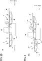
- FIG. 2A is a top view of an upstream support stand 6 and a downstream support stand 7 in the image forming apparatus 100.
- FIG. 2B is a cross-sectional view of the upstream support stand 6 and the downstream support stand 7 along a line C-C of FIG. 2A .
- the image forming apparatus 100 includes the upstream support stand 6, the downstream support stand 7, and a base portion 10.
- the base portion 10 is a component on which the platen 1 is placed.
- the registration roller pair 3 includes an upper roller 31 serving as an upper rotator and a lower roller 32 serving as a lower rotator paired with each other.
- the registration roller pair 3 conveys the plate-shaped printing medium P along the conveyance direction B while nipping the plate-shaped printing medium P between the upper roller 31 and the lower roller 32.
- the upstream support stand 6 supports an upstream side of the plate-shaped printing medium P in the conveyance direction when the plate-shaped printing medium P is fed by the registration roller pair 3.
- the upstream support stand 6 is disposed upstream from the platen 1 along the conveyance direction B and supports the plate-shaped printing medium P from below in the vertical direction (+Z direction).
- the upstream support stand 6 includes upstream mounts 61a and 61b, an upstream outer frame 62, upstream supporters 63, and an upstream reinforcing member 64.
- Materials of the above-described components are not particularly limited.
- the components may include a material such as metal or resin, for example.
- Each of the upstream mounts 61a and 61b is an example of a mount of the upstream support stand 6.
- the upstream mounts 61a and 61b are detachably attached to the registration roller pair 3, and abut against the registration roller pair 3 so that the upstream support stand 6 is positioned with respect to the registration roller pair 3.
- Each of the upstream mounts 61a and 61b is a columnar member.
- the upstream mounts 61a and 61b are disposed on both sides of the platen 1 along the main scanning directions A.
- Each of the upstream mounts 61a and 61b abuts against the registration roller pair 3.
- the upstream support stand 6 is attached to the registration roller pair 3 while being positioned with respect to the registration roller pair 3.
- the upstream support stand 6 is detached from the registration roller pair 3.
- the upstream mounts 61a and 61b have substantially the same configuration except for the positions where the upstream mounts 61a and 61b are disposed, the upstream mounts 61a and 61b may be collectively referred to as the upstream mount 61 or upstream mounts 61 below unless particularly distinguished.
- the upstream outer frame 62 is a rectangular frame-shaped member in which four columnar members serving as respective sides of a rectangle are coupled by screws.
- Each of the upstream supporters 63 is a beam that is suspended between the columnar members of the upstream outer frame 62 and extends along the conveyance direction B.
- the upstream supporters 63 include four beams, which are suspended between the two columnar members extending along the main scanning directions A of the upstream outer frame 62.
- Each of the four upstream supporters 63 contacts the plate-shaped printing medium P with a side surface in the +Z direction and supports the plate-shaped printing medium P from below in the +Z direction.
- the upstream supporters 63 also have a function of reinforcing the mechanical strength of the upstream support stand 6 by being suspended between the columnar members of the upstream outer frame 62.
- the upstream reinforcing member 64 is a beam that is suspended between the columnar members of the upstream outer frame 62 and extends along the main scanning directions A.
- the upstream reinforcing member 64 includes one beam, which is suspended between the two columnar members extending along the conveyance direction B of the upstream outer frame 62.
- the weight of the upstream support stand 6 is reduced as the upstream support stand 6 includes the upstream outer frame 62, which is a frame-shaped member.
- the upstream supporters 63 and the upstream reinforcing member 64 of the upstream support stand 6 reinforce the mechanical strength of the upstream outer frame 62 and prevents bending of the upstream support stand 6.
- the downstream support stand 7 supports a downstream side of the plate-shaped printing medium P in the conveyance direction when the plate-shaped printing medium P is conveyed by the registration roller pair 3.
- the downstream support stand 7 is disposed downstream from the platen 1 along the conveyance direction B and supports the plate-shaped printing medium P from below in the +Z direction.
- the downstream support stand 7 includes downstream mounts 71a and 71b, a downstream outer frame 72, downstream supporters 73, and a downstream reinforcing member 74.
- Materials of the above-described components are not particularly limited.
- the components may include a material such as metal or resin, for example.
- Each of the downstream mounts 71a and 71b is an example of a mount of the downstream support stand 7.
- the downstream mounts 71a and 71b are detachably attached to the registration roller pair 3, and abut against the registration roller pair 3 so that the downstream support stand 7 is positioned with respect to the registration roller pair 3.
- downstream support stand 7 is attached to the registration roller pair 3 while being positioned with respect to the registration roller pair 3.
- downstream support stand 7 is detached from the registration roller pair 3.
- Each of the downstream mounts 71a and 71b is a columnar member.
- the downstream mounts 71a and 71b are disposed on both sides of the platen 1 along the main scanning directions A.
- Each of the downstream mounts 71a and 71b abuts against the registration roller pair 3.
- the downstream mounts 71a and 71b are not necessarily limited to those attached to the registration roller pair 3.
- another roller as a second roller may be disposed downstream from the platen 1, and the downstream mounts 71a and 71b may be attached to the second roller.
- the downstream support stand 7 is positioned with respect to the second roller.
- downstream mounts 71a and 71b have substantially the same configuration except for the positions where the downstream mounts 71a and 71b are disposed, the downstream mounts 71a and 71b may be collectively referred to as the downstream mount 71 or downstream mounts 71 below unless particularly distinguished.
- the downstream outer frame 72 is a rectangular frame-shaped member in which four columnar members serving as respective sides of a rectangle are coupled by screws.
- Each of the downstream supporters 73 is a beam that is suspended between the columnar members of the downstream outer frame 72 and extends along the conveyance direction B.
- the downstream supporters 73 include four beams, which are suspended between the two columnar members extending along the main scanning directions A of the downstream outer frame 72.
- Each of the four downstream supporters 73 contacts the plate-shaped printing medium P with a side surface in the +Z direction and supports the plate-shaped printing medium P from below in the +Z direction.
- the downstream supporters 73 also have a function of reinforcing the mechanical strength of the downstream support stand 7 by being suspended between the columnar members of the downstream outer frame 72.
- the downstream reinforcing member 74 is a beam that is suspended between the columnar members of the downstream outer frame 72 and extends along the main scanning directions A.
- the downstream reinforcing member 74 includes one beam, which is suspended between the two columnar members extending along the conveyance direction B of the downstream outer frame 72.
- the weight of the downstream support stand 7 is reduced as the downstream support stand 7 includes the downstream outer frame 72, which is a frame-shaped member.
- the downstream supporter 73 and the downstream reinforcing member 74 of the downstream support stand 7 reinforces the mechanical strength of the downstream outer frame 72 and prevents bending of the downstream support stand 7.
- the configurations of the upstream support stand 6 and the downstream support stand 7 are not limited to the configurations illustrated in FIGS. 2A and 2B , and may be changed as appropriate for the size and weight of the plate-shaped printing medium P.
- FIG. 3 is a cross-sectional view of an upstream support stand 6c and a downstream support stand 7c according to a first modification.
- an upstream side of the upstream support stand 6c in the conveyance direction is higher than a downstream side of the upstream support stand 6c in the conveyance direction.
- a downstream side of the downstream support stand 7c in the conveyance direction is lower than an upstream side of the downstream support stand 7c in the conveyance direction.
- the upstream support stand 6 and the downstream support stand 7 may be inclined. However, only one of the upstream support stand 6c and the downstream support stand 7c may be inclined.
- FIG. 4A is a diagram illustrating a case where the upstream mount 61 is attached to the upper roller 31.
- FIG. 4B is a diagram illustrating a case where the upstream mount 61 is attached to the lower roller 32.
- the upstream mount 61 has a recess 611 at one end thereof.
- the recess 611 is a recess having a substantially V-shaped cross section substantially orthogonal to an axial direction of the registration roller pair 3. Further, the recess 611 as a substantially V-shaped recess penetrates the upstream mount 61 along the axial direction of the registration roller pair 3.
- the upstream support stand 6 is positioned with respect to the registration roller pair 3. That is, the registration roller pair 3 is paired, and the upstream mount 61 of the upstream support stand 6 is attached to the upper roller 31, which is disposed above the lower roller 32 in the vertical direction.
- the shape of the recess 611 is not necessarily a substantially V-shaped cross-sectional shape, and may be, for example, a rectangular cross-sectional shape. From a viewpoint of positioning stability, the recess 611 preferably has a substantially V-shaped cross-sectional shape to stably abut against the circumferential surface of the shaft 31a.
- a conveyance surface 66 illustrated in FIG. 4B indicates a surface on which the upstream mount 61 contacts the plate-shaped printing medium P when the plate-shaped printing medium P is conveyed.
- the conveyance surface 66 corresponds to a surface of the upstream supporter 63 in the +Z direction.
- the upstream support stand 6 is attached to the lower roller 32 via the upstream mount 61 so that the height along the Z direction of the conveyance surface 66 easily matches the height along the Z direction of the circumferential surface of the lower roller 32 which the plate-shaped printing medium P contacts when the plate-shaped printing medium P is conveyed. That is, the registration roller pair 3 is paired, and the upstream mount 61 of the upstream support stand 6 is attached to the lower roller 32, which is disposed below the upper roller 31 in the vertical direction. As a result, the skew of the plate-shaped printing medium P is more suitably prevented when the plate-shaped printing medium P is conveyed.
- the downstream support stand 7 is also attachable to the lower roller 32, and substantially the same effects as described above are obtained. That is, the downstream mount 71 of the downstream support stand 7 may be attached to the upper roller 31, which is disposed above the lower roller 32 in the vertical direction, or may be attached to the lower roller 32, which is disposed below the upper roller 31 in the vertical direction. In one embodiment, the upstream support stand 6 may be attached to the upper roller 31; whereas the downstream support stand 7 may be attached to the lower roller 32. Thus, the upstream support stand 6 and the downstream support stand 7 may be attached to different rollers.
- FIG. 5A is a diagram illustrating a configuration of an upstream mount 61c before being locked by an auxiliary member according to a modification.
- FIG. 5B is a diagram illustrating a configuration of the upstream mount 61c locked by the auxiliary member.
- the image forming apparatus 100 includes an auxiliary member 65.
- the auxiliary member 65 is disposed on a lower surface of the upstream mount 61c and is movable in the conveyance direction B.
- the auxiliary member 65 assists detachment of the upstream mount 61c from the shaft 31a.
- the auxiliary member 65 includes a slope 651 and is disposed to be movable along a moving direction D. As illustrated in FIG. 5A , the auxiliary member 65 does not contact the shaft 31a before locking the upstream mount 61c. At the time of locking the upstream mount 61c, the auxiliary member 65 moves along the moving direction D until the slope 651 contacts the circumferential surface of the shaft 31a.
- the recess 611 simply abutting against the shaft 31a may cause the shaft 31a and the upstream mount 61c to be detached from each other through an open side of the recess 611. Since the slope 651 of the auxiliary member 65 contacts the circumferential surface of the shaft 31a, detachment of the upstream mount 61c abutting against the shaft 31a from the shaft 31a is prevented.
- the auxiliary member 65 is moved in a direction opposite the moving direction D. As a result, one side of the recess 611 is opened, and thus the upstream mount 61c is detached such that the shaft 31a passes through the open side of the recess 611.
- FIGS. 5A and 5B the positioning of the upstream support stand 6 by the upstream mount 61c has been described. Substantially the same applies to the positioning of the downstream support stand 7, and therefore redundant description is omitted here.
- a plate-shaped printing medium itself is larger than the weight of a sheet-shaped printing medium such as a sheet of paper, conveying resistance may increase and the plate-shaped printing medium may be skewed.
- an auxiliary conveyance member such as an upstream support stand or a downstream support stand is detachably attached to an image forming apparatus.
- the conveyance auxiliary member is attached so as to be inclined with respect to the conveyance direction, a force in an oblique direction is applied to a conveyor such as a registration roller pair, and thus the plate-shaped printing medium may be skewed.
- FIG. 6 is a diagram illustrating a configuration of an image forming apparatus 100X according to a comparative example. Components having functions equivalent to those of the image forming apparatus 100 according to the present embodiment are denoted by the same reference numerals for the sake of convenience, and redundant description is omitted.
- the image forming apparatus 100X includes an upstream support stand 6X and a downstream support stand 7X.
- the upstream support stand 6X includes upstream mounts 61Xa and 61Xb (hereinafter, simply referred to as upstream mount 61X).
- the downstream support stand 7X includes downstream mounts 71Xa and 71Xb (hereinafter, simply referred to as downstream mount 71X).
- the upstream mount 61X is attached to the base portion 10, and the downstream mount 71X is similarly attached to the base portion 10.
- the upstream mount 61X and the downstream mount 71X are attached to an exterior member of the image forming apparatus 100X.
- the plate-shaped printing medium P may not be supported at a correct position and may be skewed.
- the plate-shaped printing medium P is not conveyed correctly, leading to a conveyance problem.
- the conveyance problem occurs, it eventually prevents formation of an image at a correct position and leads to deterioration of an image quality.
- the upstream support stand 6 has the upstream mount 61.
- the upstream mount 61 is detachably attached to the registration roller pair 3 (rotator).
- the upstream support stand 6 Since the upstream support stand 6 is directly positioned with respect to the registration roller pair 3, a positional deviation between a surface on which the upstream mount 61 supports the plate-shaped printing medium P and a surface on which the registration roller pair 3 contacts the plate-shaped printing medium P can be reduced. Accordingly, a problem that the upstream support stand 6 is mounted in an inclined manner can be prevented and the plate-shaped printing medium can be supported at a correct position compared to a case where the upstream support stand is positioned with respect to a component other than the registration roller pair 3, such as the base portion 10 or an exterior member. As a result, conveyance problems can be prevented.
- the image forming apparatus 100 includes an auxiliary member 65 that assists detachment of an upstream mount 61 from the shaft 31a.
- the slope 651 contacts the circumferential surface of the shaft 31a by the auxiliary member 65, to prevent a problem that the upstream mount 61 abutted against the registration roller pair 3 be detached from the registration roller pair 3.
- the same effect can be obtained in a case where the auxiliary member 65 is disposed on the downstream mount 71.
- FIG. 7 is a diagram illustrating a configuration of an upstream support stand 6 and a downstream support stand 7a disposed in an image forming apparatus 100a according to a modification.
- the downstream support stand 7a includes a downstream outer frame 72a, a downstream mount 71aa, and a downstream mount 71ab.
- the downstream outer frame 72a is provided with extending portions 75a and 75b on the side facing the registration roller pair 3.
- the extending portions 75a and 75b are portions of columnar members parallel to the conveyance direction B, among the four columnar members included in the downstream outer frame 72a, that extend toward the side facing the registration roller pair 3.
- the extending portions 75a and 75b are provided with the downstream mount 71a and 71b, respectively, at leading ends facing the registration roller pair 3.
- the downstream mount 71 is longer than the upstream mount 61 in the conveyance direction B to attach the downstream support stand 7 to the registration roller pair 3.
- the downstream outer frame 72a includes the extending portions 75a and 75b, and thus the length of each of the downstream mount 71aa and 71ab along the conveyance direction B is substantially equal to the length of the upstream mount 61.
- the rigidity of the extending portions 75a and 75b is higher than the rigidity of the downstream mounts 71aa and 71ab so that the downstream support stand 7a can be attached more stably to the registration roller pair 3.
- FIG. 8 is a diagram illustrating a configuration in which the upstream mount is attached to the registration roller pair 3 via a bearing. As illustrated in FIG. 8 , a bearing 33a is disposed on the shaft 31a of the upper roller 31 included in the registration roller pair 3.
- the bearing 33a is disposed in contact with an outer circumferential surface of the shaft 31a such that the shaft 31a is rotatable.
- the bearing 33a includes a bearing member such as a ball or a needle inside and contacts the outer circumferential surface of the shaft 31a via the bearing member.
- the upstream mount 61a of the upstream support stand 6 is attached to the bearing 33a. Note that the length (width) of the bearing 33a along the shaft 31a may span at least an area in which the upstream mount 61a contacts the shaft 31a.
- the upstream mount 61 is attached to the registration roller pair 3 via the bearing 33a without direct contact between the upstream mount 61 and the registration roller pair 3.
- the registration roller pair 3 rotates, the registration roller pair 3 smoothly rotates, and wear of the registration roller pair 3 can be reduced.
- the upstream mount 61 may be attached to the registration roller pair 3 via a member other than the bearing 33a.
- a member other than the bearing 33a is a rotating collar member, for example.
- the upstream mount 61b can be attached to the registration roller pair 3 via the bearing 33a.
- the downstream support stand 7 can be attached to the registration roller pair 3 via the bearing 33a. In either case, substantially the same effects as described above can be obtained.
- FIG. 9 is a view of a part of the upstream support stand 6 provided with rollers 101.
- the upstream support stand 6 provided with the rollers 101 arranged side by side in the conveyance direction and the image forming apparatus main body provided with the registration roller pair 3 are positioned, thus allowing a conveyance direction of the plate-shaped printing medium by the rollers 101 to match a conveyance direction of the plate-shaped printing medium by the registration roller pair 3.
- FIG. 9 illustrates a roller supporter 102, an upstream outer frame 62, and an upstream supporter 63.
- FIG. 10 is a diagram illustrating a configuration of the image forming apparatus 100b.
- the image forming apparatus 100b includes an exterior member 8, a main body support 9, an upstream support 67, and a downstream support 77.
- the exterior member 8 functions as an exterior that covers the platen 1, the registration roller pair 3, and the carriage 26.
- the exterior member 8 may cover at least the registration roller pair 3.
- the main body support 9 is a member that supports the platen 1, the registration roller pair 3, the exterior member 8, and the carriage 26.
- the upstream support 67 is an example of a support that supports the upstream support stand 6.
- the downstream support 77 is a member that supports the downstream support stand 7.
- Casters 11 are disposed on the bottom portions of the main body support 9, the upstream support 67, and the downstream support 77 so as to be movable on a floor 200.
- the upstream support 67 is provided with an upstream-support-stand mounting elongated hole 671. A vicinity of the end portion opposite the registration roller pair 3 of the upstream support stand 6 is fixed to the upstream support 67 such that a fastening screw is penetrated through the upstream-support-stand mounting elongated hole 671.
- the upstream support 67 can support the upstream support stand 6 such that the upstream support stand 6 is movable along the vertical direction which is a direction along the Z axis.
- the downstream support 77 is provided with a downstream-support-stand mounting elongated hole 771.
- a vicinity of the end portion opposite the registration roller pair 3 of the downstream support stand 7 is fixed to the downstream support 77 such that a fastening screw is penetrated through the downstream-support-stand mounting elongated hole 771.
- the downstream support 77 can support the downstream support stand 7 such that the downstream support stand 7 is movable along the vertical direction which is a direction along the Z axis.
- the vicinity of the end portion opposite the registration roller pair 3 of the upstream support stand 6 can be moved along the vertical direction to adjust an inclination of the upstream support stand 6 in a flapping direction.
- Such a configuration can prevent the upstream support stand 6 from being attached in an inclined manner and more suitably prevent the plate-shaped printing medium P from skewing when the plate-shaped printing medium P is conveyed.
- the vicinity of the end portion opposite the registration roller pair 3 of the downstream support stand 7 can also be moved along the vertical direction to adjust an inclination of the downstream support stand 7 in a flapping direction.
- Such a configuration can prevent the downstream support stand 7 from being attached in an inclined manner and more suitably prevent the plate-shaped printing medium P from skewing when the plate-shaped printing medium P is conveyed.
- FIG. 11 is a view of an insertion hole 81 in the exterior member 8.
- the insertion hole 81 is a hole into which the upstream mount 61 and the downstream mount 71 are inserted from the outside of the exterior member 8.
- the exterior member 8 has the two insertion holes 81 into which the upstream mounts 61a and 61b are inserted and has the two insertion holes 81 into which the downstream mounts 71a and 71b are inserted.
- the multiple insertion holes 81 may collectively be referred to as the insertion hole 81 below.
- the respective end portions of the upstream mount 61 and the downstream mount 71 are inserted into the exterior member 8 through the insertion holes 81.
- the upstream mount 61 and the downstream mount 71 are attached to the registration roller pair 3.
- the insertion hole 81 regulates movement of the upstream mount 61 and the downstream mount 71 inserted into the insertion hole 81 in the Z direction or the X direction, so that the upstream mount 61 and the downstream mount 71 are stably attached to the registration roller pair 3.
- the insertion hole 81 can be closed by attaching a closing member 82.
- the closing member 82 functions as a cover that closes the insertion hole 81.
- the insertion hole 81 is open. Then, dust or the like may enter the inside of the exterior member 8 and adhere to the platen 1, so that the quality of image formation may deteriorate. In the state in which the insertion hole 81 is open, the appearance of the image forming apparatus 100 may be also impaired.
- the insertion hole 81 can be closed by the closing member 82, thus preventing dust or the like from entering the exterior member 8 and adhering to the platen 1 in a case where the upstream support stand 6 or the downstream support stand 7 is not attached. Such a configuration can also prevent the appearance of the image forming apparatus 100 from being impaired.
Landscapes
- Engineering & Computer Science (AREA)
- Mechanical Engineering (AREA)
- Ink Jet (AREA)
- Registering Or Overturning Sheets (AREA)
- Handling Of Sheets (AREA)
- Feeding Of Articles By Means Other Than Belts Or Rollers (AREA)
Applications Claiming Priority (1)
| Application Number | Priority Date | Filing Date | Title |
|---|---|---|---|
| JP2021058757A JP2022155319A (ja) | 2021-03-30 | 2021-03-30 | 画像形成装置 |
Publications (2)
| Publication Number | Publication Date |
|---|---|
| EP4067093A1 true EP4067093A1 (fr) | 2022-10-05 |
| EP4067093B1 EP4067093B1 (fr) | 2024-05-01 |
Family
ID=80780741
Family Applications (1)
| Application Number | Title | Priority Date | Filing Date |
|---|---|---|---|
| EP22162093.3A Active EP4067093B1 (fr) | 2021-03-30 | 2022-03-15 | Appareil de formation d'images avec support de convoyage amovible |
Country Status (3)
| Country | Link |
|---|---|
| US (1) | US11964470B2 (fr) |
| EP (1) | EP4067093B1 (fr) |
| JP (1) | JP2022155319A (fr) |
Citations (6)
| Publication number | Priority date | Publication date | Assignee | Title |
|---|---|---|---|---|
| JP2005067104A (ja) * | 2003-08-27 | 2005-03-17 | Mutoh Ind Ltd | プリンタ |
| JP2008201107A (ja) * | 2007-02-22 | 2008-09-04 | Roland Dg Corp | 画像形成装置および記録メディアの支持装置 |
| JP4199619B2 (ja) * | 2003-08-27 | 2008-12-17 | 武藤工業株式会社 | プリンタ |
| WO2010103664A1 (fr) | 2009-03-13 | 2010-09-16 | 株式会社ミマキエンジニアリング | Dispositif d'impression |
| JP2012229064A (ja) * | 2011-04-22 | 2012-11-22 | Roland Dg Corp | 画像形成装置 |
| US8490964B2 (en) * | 2009-09-10 | 2013-07-23 | James C. Kaiping | Document feeder with pivoting delivery table, particularly for digital printers |
Family Cites Families (19)
| Publication number | Priority date | Publication date | Assignee | Title |
|---|---|---|---|---|
| JP5304346B2 (ja) | 2009-03-12 | 2013-10-02 | 株式会社リコー | 画像形成装置 |
| JP5464353B2 (ja) | 2009-05-20 | 2014-04-09 | 株式会社リコー | 画像形成装置 |
| JP2011083973A (ja) | 2009-10-15 | 2011-04-28 | Mimaki Engineering Co Ltd | プリンタ装置 |
| JP5463883B2 (ja) | 2009-12-03 | 2014-04-09 | 株式会社リコー | 画像形成装置 |
| JP5663867B2 (ja) | 2009-12-07 | 2015-02-04 | 株式会社リコー | 画像形成装置 |
| US8414105B2 (en) | 2009-12-11 | 2013-04-09 | Ricoh Company, Ltd. | Image forming apparatus |
| JP5333282B2 (ja) | 2010-02-17 | 2013-11-06 | 株式会社リコー | 画像形成装置 |
| JP5353755B2 (ja) | 2010-02-19 | 2013-11-27 | 株式会社リコー | 画像形成装置 |
| JP5533037B2 (ja) | 2010-03-02 | 2014-06-25 | 株式会社リコー | 画像形成装置 |
| JP5838595B2 (ja) | 2010-09-08 | 2016-01-06 | 株式会社リコー | 画像形成装置 |
| JP2012076450A (ja) | 2010-09-09 | 2012-04-19 | Ricoh Co Ltd | 画像形成装置 |
| US9002257B2 (en) | 2011-08-01 | 2015-04-07 | Ricoh Company, Ltd. | Image forming apparatus |
| JP5954061B2 (ja) | 2012-09-05 | 2016-07-20 | 株式会社リコー | 画像形成装置 |
| JP5958367B2 (ja) | 2013-01-31 | 2016-07-27 | ブラザー工業株式会社 | 記録装置 |
| JP6578647B2 (ja) | 2014-10-31 | 2019-09-25 | 株式会社リコー | 画像形成装置 |
| JP6471595B2 (ja) | 2015-04-13 | 2019-02-20 | 株式会社リコー | 画像形成装置 |
| EP3395576B1 (fr) | 2017-04-26 | 2021-10-27 | Ricoh Company, Ltd. | Appareil de décharge de liquide |
| JP2020121480A (ja) | 2019-01-30 | 2020-08-13 | 株式会社リコー | 記録媒体支持装置および画像形成装置 |
| JP2021011036A (ja) | 2019-07-04 | 2021-02-04 | 株式会社リコー | 液体吐出ユニット及び液体吐出装置 |
-
2021
- 2021-03-30 JP JP2021058757A patent/JP2022155319A/ja active Pending
-
2022
- 2022-03-15 EP EP22162093.3A patent/EP4067093B1/fr active Active
- 2022-03-16 US US17/696,109 patent/US11964470B2/en active Active
Patent Citations (6)
| Publication number | Priority date | Publication date | Assignee | Title |
|---|---|---|---|---|
| JP2005067104A (ja) * | 2003-08-27 | 2005-03-17 | Mutoh Ind Ltd | プリンタ |
| JP4199619B2 (ja) * | 2003-08-27 | 2008-12-17 | 武藤工業株式会社 | プリンタ |
| JP2008201107A (ja) * | 2007-02-22 | 2008-09-04 | Roland Dg Corp | 画像形成装置および記録メディアの支持装置 |
| WO2010103664A1 (fr) | 2009-03-13 | 2010-09-16 | 株式会社ミマキエンジニアリング | Dispositif d'impression |
| US8490964B2 (en) * | 2009-09-10 | 2013-07-23 | James C. Kaiping | Document feeder with pivoting delivery table, particularly for digital printers |
| JP2012229064A (ja) * | 2011-04-22 | 2012-11-22 | Roland Dg Corp | 画像形成装置 |
Also Published As
| Publication number | Publication date |
|---|---|
| JP2022155319A (ja) | 2022-10-13 |
| EP4067093B1 (fr) | 2024-05-01 |
| US11964470B2 (en) | 2024-04-23 |
| US20220314660A1 (en) | 2022-10-06 |
Similar Documents
| Publication | Publication Date | Title |
|---|---|---|
| US6672705B2 (en) | Printer | |
| JP5181686B2 (ja) | 画像形成装置 | |
| EP3395576B1 (fr) | Appareil de décharge de liquide | |
| JP6005471B2 (ja) | インクジェットプリンタ、被印刷体保持部材、及び印刷方法 | |
| JP2010030271A (ja) | 液体吐出ヘッドユニット及び画像形成装置 | |
| US8297733B2 (en) | Ink jet recording apparatus having recovery device | |
| JP4695565B2 (ja) | 画像形成装置 | |
| EP4067093B1 (fr) | Appareil de formation d'images avec support de convoyage amovible | |
| JP2007276289A (ja) | キャリッジ取付位置調整機構及び液体噴射装置と記録装置 | |
| JP2011230315A (ja) | 描画装置 | |
| JP6801441B2 (ja) | ヘッド位置調整機構、液体吐出ユニット及び液体吐出装置 | |
| US20220314663A1 (en) | Image forming apparatus | |
| JP2014054849A (ja) | 液体吐出ヘッドユニット及び画像形成装置 | |
| JP2006231737A (ja) | 画像形成装置 | |
| US10807367B2 (en) | Liquid discharge device and liquid discharge apparatus including liquid discharge device | |
| JP2022155486A (ja) | 画像形成装置 | |
| JP2010046886A (ja) | 印刷装置 | |
| JP2010052888A (ja) | 印刷装置 | |
| US11370237B2 (en) | Roll medium holding device and image forming apparatus incorporating same | |
| JP4919841B2 (ja) | 画像形成装置 | |
| JP2884544B2 (ja) | 記録装置 | |
| JP2018183977A (ja) | 液体吐出装置 | |
| JP7010150B2 (ja) | 液体吐出ユニット及び液体吐出装置 | |
| JP2001334652A (ja) | キャリッジにおける記録ヘッド取り付け装置 | |
| JP2019055509A (ja) | 液体吐出ヘッド取り付け構造、液体吐出ユニットおよび液体を吐出する装置 |
Legal Events
| Date | Code | Title | Description |
|---|---|---|---|
| PUAI | Public reference made under article 153(3) epc to a published international application that has entered the european phase |
Free format text: ORIGINAL CODE: 0009012 |
|
| STAA | Information on the status of an ep patent application or granted ep patent |
Free format text: STATUS: REQUEST FOR EXAMINATION WAS MADE |
|
| 17P | Request for examination filed |
Effective date: 20220315 |
|
| AK | Designated contracting states |
Kind code of ref document: A1 Designated state(s): AL AT BE BG CH CY CZ DE DK EE ES FI FR GB GR HR HU IE IS IT LI LT LU LV MC MK MT NL NO PL PT RO RS SE SI SK SM TR |
|
| GRAP | Despatch of communication of intention to grant a patent |
Free format text: ORIGINAL CODE: EPIDOSNIGR1 |
|
| STAA | Information on the status of an ep patent application or granted ep patent |
Free format text: STATUS: GRANT OF PATENT IS INTENDED |
|
| RIC1 | Information provided on ipc code assigned before grant |
Ipc: B65H 5/36 20060101ALI20231010BHEP Ipc: B65H 5/06 20060101ALI20231010BHEP Ipc: B41J 13/00 20060101ALI20231010BHEP Ipc: B65H 11/00 20060101ALI20231010BHEP Ipc: B41J 13/10 20060101ALI20231010BHEP Ipc: B41J 3/407 20060101AFI20231010BHEP |
|
| INTG | Intention to grant announced |
Effective date: 20231106 |
|
| GRAS | Grant fee paid |
Free format text: ORIGINAL CODE: EPIDOSNIGR3 |
|
| P01 | Opt-out of the competence of the unified patent court (upc) registered |
Effective date: 20240125 |
|
| GRAA | (expected) grant |
Free format text: ORIGINAL CODE: 0009210 |
|
| STAA | Information on the status of an ep patent application or granted ep patent |
Free format text: STATUS: THE PATENT HAS BEEN GRANTED |
|
| AK | Designated contracting states |
Kind code of ref document: B1 Designated state(s): AL AT BE BG CH CY CZ DE DK EE ES FI FR GB GR HR HU IE IS IT LI LT LU LV MC MK MT NL NO PL PT RO RS SE SI SK SM TR |
|
| REG | Reference to a national code |
Ref country code: GB Ref legal event code: FG4D |
|
| REG | Reference to a national code |
Ref country code: CH Ref legal event code: EP |
|
| REG | Reference to a national code |
Ref country code: IE Ref legal event code: FG4D |
|
| REG | Reference to a national code |
Ref country code: DE Ref legal event code: R096 Ref document number: 602022003119 Country of ref document: DE |