EP4065857B1 - Scheibenbremse für ein nutzfahrzeug - Google Patents
Scheibenbremse für ein nutzfahrzeug Download PDFInfo
- Publication number
- EP4065857B1 EP4065857B1 EP20806952.6A EP20806952A EP4065857B1 EP 4065857 B1 EP4065857 B1 EP 4065857B1 EP 20806952 A EP20806952 A EP 20806952A EP 4065857 B1 EP4065857 B1 EP 4065857B1
- Authority
- EP
- European Patent Office
- Prior art keywords
- brake
- pad
- disc
- disc brake
- spring
- Prior art date
- Legal status (The legal status is an assumption and is not a legal conclusion. Google has not performed a legal analysis and makes no representation as to the accuracy of the status listed.)
- Active
Links
Images


Classifications
-
- F—MECHANICAL ENGINEERING; LIGHTING; HEATING; WEAPONS; BLASTING
- F16—ENGINEERING ELEMENTS AND UNITS; GENERAL MEASURES FOR PRODUCING AND MAINTAINING EFFECTIVE FUNCTIONING OF MACHINES OR INSTALLATIONS; THERMAL INSULATION IN GENERAL
- F16D—COUPLINGS FOR TRANSMITTING ROTATION; CLUTCHES; BRAKES
- F16D65/00—Parts or details
- F16D65/02—Braking members; Mounting thereof
- F16D65/04—Bands, shoes or pads; Pivots or supporting members therefor
- F16D65/092—Bands, shoes or pads; Pivots or supporting members therefor for axially-engaging brakes, e.g. disc brakes
- F16D65/095—Pivots or supporting members therefor
- F16D65/097—Resilient means interposed between pads and supporting members or other brake parts
-
- F—MECHANICAL ENGINEERING; LIGHTING; HEATING; WEAPONS; BLASTING
- F16—ENGINEERING ELEMENTS AND UNITS; GENERAL MEASURES FOR PRODUCING AND MAINTAINING EFFECTIVE FUNCTIONING OF MACHINES OR INSTALLATIONS; THERMAL INSULATION IN GENERAL
- F16D—COUPLINGS FOR TRANSMITTING ROTATION; CLUTCHES; BRAKES
- F16D55/00—Brakes with substantially-radial braking surfaces pressed together in axial direction, e.g. disc brakes
- F16D55/02—Brakes with substantially-radial braking surfaces pressed together in axial direction, e.g. disc brakes with axially-movable discs or pads pressed against axially-located rotating members
- F16D55/22—Brakes with substantially-radial braking surfaces pressed together in axial direction, e.g. disc brakes with axially-movable discs or pads pressed against axially-located rotating members by clamping an axially-located rotating disc between movable braking members, e.g. movable brake discs or brake pads
- F16D55/224—Brakes with substantially-radial braking surfaces pressed together in axial direction, e.g. disc brakes with axially-movable discs or pads pressed against axially-located rotating members by clamping an axially-located rotating disc between movable braking members, e.g. movable brake discs or brake pads with a common actuating member for the braking members
- F16D55/225—Brakes with substantially-radial braking surfaces pressed together in axial direction, e.g. disc brakes with axially-movable discs or pads pressed against axially-located rotating members by clamping an axially-located rotating disc between movable braking members, e.g. movable brake discs or brake pads with a common actuating member for the braking members the braking members being brake pads
- F16D55/226—Brakes with substantially-radial braking surfaces pressed together in axial direction, e.g. disc brakes with axially-movable discs or pads pressed against axially-located rotating members by clamping an axially-located rotating disc between movable braking members, e.g. movable brake discs or brake pads with a common actuating member for the braking members the braking members being brake pads in which the common actuating member is moved axially, e.g. floating caliper disc brakes
-
- F—MECHANICAL ENGINEERING; LIGHTING; HEATING; WEAPONS; BLASTING
- F16—ENGINEERING ELEMENTS AND UNITS; GENERAL MEASURES FOR PRODUCING AND MAINTAINING EFFECTIVE FUNCTIONING OF MACHINES OR INSTALLATIONS; THERMAL INSULATION IN GENERAL
- F16D—COUPLINGS FOR TRANSMITTING ROTATION; CLUTCHES; BRAKES
- F16D65/00—Parts or details
- F16D65/02—Braking members; Mounting thereof
- F16D65/04—Bands, shoes or pads; Pivots or supporting members therefor
- F16D65/092—Bands, shoes or pads; Pivots or supporting members therefor for axially-engaging brakes, e.g. disc brakes
- F16D65/095—Pivots or supporting members therefor
- F16D65/097—Resilient means interposed between pads and supporting members or other brake parts
- F16D65/0972—Resilient means interposed between pads and supporting members or other brake parts transmitting brake reaction force, e.g. elements interposed between torque support plate and pad
-
- F—MECHANICAL ENGINEERING; LIGHTING; HEATING; WEAPONS; BLASTING
- F16—ENGINEERING ELEMENTS AND UNITS; GENERAL MEASURES FOR PRODUCING AND MAINTAINING EFFECTIVE FUNCTIONING OF MACHINES OR INSTALLATIONS; THERMAL INSULATION IN GENERAL
- F16D—COUPLINGS FOR TRANSMITTING ROTATION; CLUTCHES; BRAKES
- F16D65/00—Parts or details
- F16D65/02—Braking members; Mounting thereof
- F16D65/04—Bands, shoes or pads; Pivots or supporting members therefor
- F16D65/092—Bands, shoes or pads; Pivots or supporting members therefor for axially-engaging brakes, e.g. disc brakes
- F16D65/095—Pivots or supporting members therefor
- F16D65/097—Resilient means interposed between pads and supporting members or other brake parts
- F16D65/0973—Resilient means interposed between pads and supporting members or other brake parts not subjected to brake forces
- F16D65/0974—Resilient means interposed between pads and supporting members or other brake parts not subjected to brake forces acting on or in the vicinity of the pad rim in a direction substantially transverse to the brake disc axis
- F16D65/0975—Springs made from wire
- F16D65/0976—Springs made from wire acting on one pad only
-
- F—MECHANICAL ENGINEERING; LIGHTING; HEATING; WEAPONS; BLASTING
- F16—ENGINEERING ELEMENTS AND UNITS; GENERAL MEASURES FOR PRODUCING AND MAINTAINING EFFECTIVE FUNCTIONING OF MACHINES OR INSTALLATIONS; THERMAL INSULATION IN GENERAL
- F16D—COUPLINGS FOR TRANSMITTING ROTATION; CLUTCHES; BRAKES
- F16D65/00—Parts or details
- F16D65/02—Braking members; Mounting thereof
- F16D65/04—Bands, shoes or pads; Pivots or supporting members therefor
- F16D65/092—Bands, shoes or pads; Pivots or supporting members therefor for axially-engaging brakes, e.g. disc brakes
- F16D65/095—Pivots or supporting members therefor
- F16D65/097—Resilient means interposed between pads and supporting members or other brake parts
- F16D65/0973—Resilient means interposed between pads and supporting members or other brake parts not subjected to brake forces
- F16D65/0974—Resilient means interposed between pads and supporting members or other brake parts not subjected to brake forces acting on or in the vicinity of the pad rim in a direction substantially transverse to the brake disc axis
- F16D65/0977—Springs made from sheet metal
- F16D65/0978—Springs made from sheet metal acting on one pad only
-
- F—MECHANICAL ENGINEERING; LIGHTING; HEATING; WEAPONS; BLASTING
- F16—ENGINEERING ELEMENTS AND UNITS; GENERAL MEASURES FOR PRODUCING AND MAINTAINING EFFECTIVE FUNCTIONING OF MACHINES OR INSTALLATIONS; THERMAL INSULATION IN GENERAL
- F16D—COUPLINGS FOR TRANSMITTING ROTATION; CLUTCHES; BRAKES
- F16D65/00—Parts or details
- F16D65/02—Braking members; Mounting thereof
- F16D65/04—Bands, shoes or pads; Pivots or supporting members therefor
- F16D65/092—Bands, shoes or pads; Pivots or supporting members therefor for axially-engaging brakes, e.g. disc brakes
- F16D65/095—Pivots or supporting members therefor
- F16D65/097—Resilient means interposed between pads and supporting members or other brake parts
- F16D65/0973—Resilient means interposed between pads and supporting members or other brake parts not subjected to brake forces
- F16D65/0979—Resilient means interposed between pads and supporting members or other brake parts not subjected to brake forces acting on the rear side of the pad or an element affixed thereto, e.g. spring clips securing the pad to the brake piston or caliper
-
- F—MECHANICAL ENGINEERING; LIGHTING; HEATING; WEAPONS; BLASTING
- F16—ENGINEERING ELEMENTS AND UNITS; GENERAL MEASURES FOR PRODUCING AND MAINTAINING EFFECTIVE FUNCTIONING OF MACHINES OR INSTALLATIONS; THERMAL INSULATION IN GENERAL
- F16D—COUPLINGS FOR TRANSMITTING ROTATION; CLUTCHES; BRAKES
- F16D65/00—Parts or details
- F16D65/14—Actuating mechanisms for brakes; Means for initiating operation at a predetermined position
- F16D65/16—Actuating mechanisms for brakes; Means for initiating operation at a predetermined position arranged in or on the brake
- F16D65/18—Actuating mechanisms for brakes; Means for initiating operation at a predetermined position arranged in or on the brake adapted for drawing members together, e.g. for disc brakes
-
- F—MECHANICAL ENGINEERING; LIGHTING; HEATING; WEAPONS; BLASTING
- F16—ENGINEERING ELEMENTS AND UNITS; GENERAL MEASURES FOR PRODUCING AND MAINTAINING EFFECTIVE FUNCTIONING OF MACHINES OR INSTALLATIONS; THERMAL INSULATION IN GENERAL
- F16D—COUPLINGS FOR TRANSMITTING ROTATION; CLUTCHES; BRAKES
- F16D55/00—Brakes with substantially-radial braking surfaces pressed together in axial direction, e.g. disc brakes
- F16D2055/0004—Parts or details of disc brakes
- F16D2055/0016—Brake calipers
- F16D2055/0029—Retraction devices
-
- F—MECHANICAL ENGINEERING; LIGHTING; HEATING; WEAPONS; BLASTING
- F16—ENGINEERING ELEMENTS AND UNITS; GENERAL MEASURES FOR PRODUCING AND MAINTAINING EFFECTIVE FUNCTIONING OF MACHINES OR INSTALLATIONS; THERMAL INSULATION IN GENERAL
- F16D—COUPLINGS FOR TRANSMITTING ROTATION; CLUTCHES; BRAKES
- F16D55/00—Brakes with substantially-radial braking surfaces pressed together in axial direction, e.g. disc brakes
- F16D2055/0004—Parts or details of disc brakes
- F16D2055/007—Pins holding the braking members
-
- F—MECHANICAL ENGINEERING; LIGHTING; HEATING; WEAPONS; BLASTING
- F16—ENGINEERING ELEMENTS AND UNITS; GENERAL MEASURES FOR PRODUCING AND MAINTAINING EFFECTIVE FUNCTIONING OF MACHINES OR INSTALLATIONS; THERMAL INSULATION IN GENERAL
- F16D—COUPLINGS FOR TRANSMITTING ROTATION; CLUTCHES; BRAKES
- F16D65/00—Parts or details
- F16D65/02—Braking members; Mounting thereof
- F16D2065/13—Parts or details of discs or drums
- F16D2065/134—Connection
- F16D2065/1392—Connection elements
- F16D2065/1396—Ancillary resilient elements, e.g. anti-rattle or retraction springs
Definitions
- the invention relates to a disc brake for a commercial vehicle according to the preamble of claim 1.
- the brake pads of such a sliding caliper disc brake are applied by an application device, whereby first the brake pad on the application side is pressed against the brake disc and then the opposite, reaction-side brake pad is pressed against the brake disc.
- the action-side brake pad is pressed against the brake disc via the brake piston of the application device, while in order to press the reaction-side brake pad, the brake caliper, which is designed as a sliding caliper, is moved against the application direction of the action-side brake pad.
- the brake caliper of the well-known disc brake remains in this latter position, in which the brake pads, or at least the reaction side, are in contact with the brake disc without pressure but with abrasive action.
- the brake pads may become slightly loosened due to the brake disc wobbling and due to vibrations and lateral acceleration when cornering, but these effects are not sufficient to effectively prevent the aforementioned grinding.
- Each brake pad is assigned a spreading element, each with two spring arms that engage with the respective pad carrier plate.
- expansion elements are attached to a bracket that extends essentially parallel to the brake disc, which in turn is held to a brake carrier on the vehicle. This design prevents residual grinding torques from occurring, which lead to increased wear of the brake pads.
- a disc brake with a stationary brake carrier which has two pad shafts for receiving the brake pads, wherein each pad shaft is delimited in both circumferential directions of the brake disc by brake carrier horns, on which a pad carrier plate of the respective brake pad carrying a friction lining is slidably supported in the application direction.
- a spring arrangement which acts axially on the brake pads in the brake release direction and which supports the adjustment of the clearance between the brake pads and the brake disc after the brake is released.
- This spring arrangement has two spring-loaded spreading elements, each with two spring arms, which rest spring-loaded on the lining carrier plate above the friction lining, with the respective spreading element being fixed to a stationary component, for example on the brake carrier.
- a spreading element comprising a locking arm that connects the spreading element to a brake pad, a retraction arm and a pre-tensioning device that is arranged between the locking arm and the retraction arm.
- the pre-tensioning device has spiral spring loops that, during a braking process, Store energy and retract the brake pad after the brake is released.
- this design does not concern a sliding caliper brake, but a floating caliper brake, which is used in a passenger vehicle but is not suitable for a commercial vehicle.
- these spreading elements consist of separate spring legs, each of which is attached at one end to the associated brake pad and at the other end to the spoke of a pad retaining bracket, wrapping around it.
- each expansion element is connected to each other by a helically wound area that wraps around a spoke of the pad retaining bracket.
- the invention is based on the object of further developing a disc brake of the generic type in such a way that its reset device is simpler in construction and can thus be manufactured more cost-effectively and its operational reliability is improved.
- the design according to the invention offers considerable advantages. These arise, among other things, from the extremely simple implementation of the invention, since only two, preferably one-piece, expansion elements are provided. After the brake is released, the brake pads are moved by the spring pressure of the spring legs tensioned during braking into a position in which they no longer rest on the brake disc.
- the expansion elements can be formed from a spring wire and are therefore not only easy to manufacture, but also have an improved service life. This is particularly important because disc brakes are safety-relevant components and are subject to special requirements.
- each expansion element allows them to be used with different brake pads that have identical positions for the ends of the spring legs to be accommodated. This enables the expansion elements to be prefabricated, which significantly reduces their procurement costs.
- each spreading element has spring legs, which at least partially run obliquely to each other towards a common connecting area.
- At least one of the spring legs is designed in such a way that it is supported on an associated pad retaining spring of the corresponding brake pad in order to prevent tipping in the direction of the brake disc, with each connecting area resting on the underside of the pad retaining bracket.
- each expansion element is fastened to the retaining bracket in the connection area of the spring legs, for example by means of clamping means.
- connection areas are prevented from rising up when the brake pads are applied by their contact with or connection to the pad retaining bracket.
- the spreading elements are designed and mounted asymmetrically so that in the event of wear of the brake pads and the resulting displacement of the connecting areas of the spreading elements, they can slide past each other under the pad retaining bracket.
- the ends of the spring legs can be fixed to the pad carrier plates in different ways, for example by inserting these ends into holes in the pad carrier plate or the pad retaining spring.
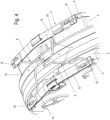
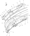
- a disc brake for a commercial vehicle according to the state of the art is shown.
- This disc brake has a brake calliper 1 which is movably held on a brake carrier 2 which can be attached to the vehicle and in which two brake pads 3 arranged at a distance from one another are mounted so as to be movable in opposite directions.
- Each brake pad 3 has a pad carrier plate 4 and a friction pad 5 fastened thereto, wherein a pad retaining spring 10 is fastened to each pad carrier plate 4, which is supported on a pad retaining bracket 11 which overlaps an assembly opening of the brake calliper 1 and by means of which the brake pads 3 are held under prestress in pad shafts of the brake carrier 2, which are laterally delimited by brake carrier horns 9.
- a return device which is formed from two spreading elements 6 which engage the pad carrier plates 4 in the areas adjacent to the brake carrier horns 9 by means of spring legs 7.
- the spreading elements 6 are also attached to a retaining bracket 8 as a further component of the reset device, which is inserted with its two ends into a brake carrier horn 9.
- This known disc brake is, as already mentioned, in the WO 2016/202778 A1 disclosed, to which express reference is made.
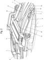
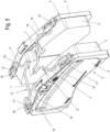
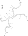
- a part of a disc brake is shown, in which, according to the invention, two V-shaped spreading elements 6 are provided, which are supported in the connecting area 13 of their respective spring legs 7 on the underside of the pad retaining bracket 11.
- the spring legs 7 of each spreading element 6 are held with their ends 15 on the opposite brake pads 3, whereby in the example according to the Figures 2 and 3 the ends 15 which are angled relative to the spring legs 7 are inserted into holes in the lining carrier plate 4.
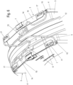
- the Fig.4 shows the design of the expansion elements 6 according to the Fig.3 In contrast, however, it is not attached directly to the pad carrier plate 4, but in holes in the pad retaining springs 10.
- the respective support 14 is only formed on one side and rests on the associated pad retaining spring 10, wherein the supports 14 of the two spreading elements 6 rest on the pad retaining springs 10 of the opposing brake pads 3.
- the two expansion elements 6 are each designed asymmetrically with respect to an imaginary longitudinal axis X passing through the apex of the connecting region 13, in such a way that the two connecting regions 13 of the expansion elements 6 are positioned offset from one another in the assembled position, with the longitudinal axes X spaced apart from one another.
- each spring leg 7 has a support 14 which rests on the associated pad retaining spring 10.
- FIG.4 A comparable design of the expansion elements 6 is shown in the Fig.6 shown, ie with only one support 14 each. However, the ends 15 of the spring legs 7 are inserted into holes in the lining carrier plate 4.
- the ends 15 of the spring legs 7 are inserted into eyelets 16 formed on the end of the respective pad retaining spring 10 and are held therein in a rotationally secure manner, so that a support 14 can be dispensed with.
- Fig.8 another variant of the connection of the spring legs 7 to the lining carrier plates 4 can be seen.
- the ends 15 are wound in such a way that a loop is formed, which is guided above the lining retaining springs 10 through tabs 17 formed on the respective lining carrier plate, which pass through the lining retaining springs 10.
- These ends 15 also serve to radially secure the lining retaining spring 10 relative to the lining carrier plate 4.
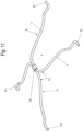
- the expansion elements 6 as a detail are shown in the Fig.9 , whereby in this embodiment the supports 14 are formed on one side, ie on one of the two spring legs 7. The ends 15 are formed at a right angle to the spring legs 7.
- the Fig.10 shows an alternative design of the holder of the expansion elements 6 on the pad retaining bracket 11.
- the connecting areas 13 rest on the pad retaining bracket 11 and are fastened there by a clamping device 19, whereby the expansion elements 6 are pre-tensioned in the radial direction for their defined positioning and to avoid noises caused by vibrations.
- the clamping device 19 is preferably held axially displaceable so that saddle movements are compensated for in the event of wear.
- the ends 15 of the spring legs 7 are guided through elongated holes 20 of the lining carrier plates 4, wherein the ends 15 are angled at a right angle in the plane of the spring legs 7.
- the two spreading elements 6 lie against one another with their connecting regions 13 and are connected to one another by a clamp 18, the spreading elements 6 not being asymmetrical but symmetrical in relation to the previously described longitudinal axis X.
Landscapes
- Engineering & Computer Science (AREA)
- General Engineering & Computer Science (AREA)
- Mechanical Engineering (AREA)
- Braking Arrangements (AREA)
Priority Applications (1)
| Application Number | Priority Date | Filing Date | Title |
|---|---|---|---|
| EP24200069.3A EP4509738A3 (de) | 2019-11-25 | 2020-11-10 | Scheibenbremse für ein nutzfahrzeug |
Applications Claiming Priority (2)
| Application Number | Priority Date | Filing Date | Title |
|---|---|---|---|
| DE102019131840.8A DE102019131840A1 (de) | 2019-11-25 | 2019-11-25 | Scheibenbremse für ein Nutzfahrzeug |
| PCT/EP2020/081679 WO2021104857A1 (de) | 2019-11-25 | 2020-11-10 | Scheibenbremse für ein nutzfahrzeug |
Related Child Applications (1)
| Application Number | Title | Priority Date | Filing Date |
|---|---|---|---|
| EP24200069.3A Division EP4509738A3 (de) | 2019-11-25 | 2020-11-10 | Scheibenbremse für ein nutzfahrzeug |
Publications (2)
| Publication Number | Publication Date |
|---|---|
| EP4065857A1 EP4065857A1 (de) | 2022-10-05 |
| EP4065857B1 true EP4065857B1 (de) | 2024-09-18 |
Family
ID=73401483
Family Applications (2)
| Application Number | Title | Priority Date | Filing Date |
|---|---|---|---|
| EP20806952.6A Active EP4065857B1 (de) | 2019-11-25 | 2020-11-10 | Scheibenbremse für ein nutzfahrzeug |
| EP24200069.3A Pending EP4509738A3 (de) | 2019-11-25 | 2020-11-10 | Scheibenbremse für ein nutzfahrzeug |
Family Applications After (1)
| Application Number | Title | Priority Date | Filing Date |
|---|---|---|---|
| EP24200069.3A Pending EP4509738A3 (de) | 2019-11-25 | 2020-11-10 | Scheibenbremse für ein nutzfahrzeug |
Country Status (11)
| Country | Link |
|---|---|
| US (1) | US12276309B2 (pl) |
| EP (2) | EP4065857B1 (pl) |
| JP (1) | JP7368626B2 (pl) |
| KR (1) | KR102750785B1 (pl) |
| CN (1) | CN114746664B (pl) |
| DE (1) | DE102019131840A1 (pl) |
| ES (1) | ES2991657T3 (pl) |
| HU (1) | HUE068982T2 (pl) |
| MX (1) | MX2022006282A (pl) |
| PL (1) | PL4065857T3 (pl) |
| WO (1) | WO2021104857A1 (pl) |
Families Citing this family (9)
| Publication number | Priority date | Publication date | Assignee | Title |
|---|---|---|---|---|
| US12071989B2 (en) * | 2020-02-12 | 2024-08-27 | Arvinmeritor Technology, Llc | Brake assembly having a retraction spring |
| EP3954919B1 (en) * | 2020-08-11 | 2024-10-02 | Meritor Heavy Vehicle Braking Systems (UK) Limited | Brake assembly |
| DE102021121995A1 (de) | 2021-08-25 | 2023-03-02 | Zf Cv Systems Europe Bv | Scheibenbremse für ein Kraftfahrzeug |
| DE102021129868B4 (de) | 2021-11-16 | 2024-07-18 | Knorr-Bremse Systeme für Nutzfahrzeuge GmbH | Scheibenbremse für ein Nutzfahrzeug |
| CN218670324U (zh) * | 2022-09-14 | 2023-03-21 | 浙江万安智驭汽车控制系统有限公司 | 一种低拖滞的卡钳结构 |
| DE102022123484A1 (de) | 2022-09-14 | 2024-03-14 | Knorr-Bremse Systeme für Nutzfahrzeuge GmbH | Scheibenbremse für ein Nutzfahrzeug |
| EP4386230A1 (en) * | 2022-12-14 | 2024-06-19 | KNORR-BREMSE Systeme für Nutzfahrzeuge GmbH | Spreading device for active caliper release |
| CN116221305A (zh) * | 2023-02-23 | 2023-06-06 | 武汉万向汽车制动器有限公司 | 摩擦片回位装置、制动卡钳总成及车辆 |
| DE102024119310A1 (de) * | 2024-07-08 | 2026-01-08 | Haldex Aktiebolag | Scheibenbremse |
Family Cites Families (27)
| Publication number | Priority date | Publication date | Assignee | Title |
|---|---|---|---|---|
| US3762509A (en) * | 1971-07-02 | 1973-10-02 | Ford Motor Co | Brake shoe construction for a motor vehicle disc brake |
| DE2931071C2 (de) * | 1979-07-31 | 1987-01-02 | Alfred Teves Gmbh, 6000 Frankfurt | Kombinierte Niederhalte-Spreizfeder |
| DE3108113A1 (de) * | 1981-03-04 | 1982-09-16 | FAG Kugelfischer Georg Schäfer & Co, 8720 Schweinfurt | Teilbelagscheibenbremse |
| JPS57179435A (en) | 1981-04-27 | 1982-11-05 | Akebono Brake Ind Co Ltd | Holder spring used in integral knuckle type disk brake |
| DE9010012U1 (de) * | 1990-07-02 | 1991-10-31 | Lucas Industries P.L.C., Birmingham, West Midlands | Bremsbacke für Teilbelag-Scheibenbremsen |
| EP0623196B1 (de) | 1992-01-28 | 1996-09-11 | ITT Automotive Europe GmbH | Schwimmsattel-scheibenbremse mit spreizfedern für die bremsbacken |
| DE102005059801A1 (de) | 2005-12-14 | 2007-06-28 | Knorr-Bremse Systeme für Nutzfahrzeuge GmbH | Bremsbelaghalterung und Bremsbelag für eine Scheibenbremse |
| JP2009127715A (ja) * | 2007-11-21 | 2009-06-11 | Akebono Brake Ind Co Ltd | ディスクブレーキ装置用リターンスプリングの配置方法、リターンスプリング、およびディスクブレーキ装置 |
| DE102011118736B4 (de) | 2011-11-17 | 2015-02-05 | Knorr-Bremse Systeme für Nutzfahrzeuge GmbH | Scheibenbremse für ein Nutzfahrzeug sowie Bremsbelag für eine Scheibenbremse |
| DE102012102584A1 (de) * | 2012-03-26 | 2013-09-26 | Knorr-Bremse Systeme für Nutzfahrzeuge GmbH | Scheibenbremse mit Rückstelleinrichtung und Bremsbelag |
| DE102012102585B4 (de) | 2012-03-26 | 2014-07-10 | Knorr-Bremse Systeme für Nutzfahrzeuge GmbH | Scheibenbremse für ein Nutzfahrzeug |
| ITPD20120398A1 (it) * | 2012-12-20 | 2014-06-21 | Freni Brembo Spa | Pinza per freno a disco |
| TWI512211B (zh) * | 2013-03-20 | 2015-12-11 | Sanyang Industry Co Ltd | 煞車卡鉗結構 |
| DE102013207424B4 (de) * | 2013-04-24 | 2025-02-20 | Continental Automotive Technologies GmbH | Federanordnung zur Lüftspielverbesserung für eine Teilbelagscheibenbremse |
| DE102013008155A1 (de) | 2013-05-13 | 2014-11-13 | Wabco Europe Bvba | Sattelscheibenbremse eines Fahrzeugs, insbesondere eines Nutzfahrzeugs, und Niederhalteeinrichtung einer solchen Bremse |
| US9261152B2 (en) * | 2013-05-14 | 2016-02-16 | Akebono Brake Corporation | Coiled spreader spring |
| DE102014019114A1 (de) | 2014-12-19 | 2016-06-23 | Knorr-Bremse Systeme für Nutzfahrzeuge GmbH | Bremsbelaghalterung |
| DE202016102686U1 (de) | 2015-06-15 | 2016-06-23 | Knorr-Bremse Systeme für Nutzfahrzeuge GmbH | Scheibenbremse für ein Nutzfahrzeug und Bremsbelagsatz |
| DE102016104967A1 (de) | 2015-10-09 | 2017-04-13 | Knorr-Bremse Systeme für Nutzfahrzeuge GmbH | Bremsträger |
| DE102015122558A1 (de) * | 2015-12-22 | 2017-06-22 | Bpw Bergische Achsen Kg | Scheibenbremse sowie Niederhalter für die Befestigung von Bremsbelägen in einer Scheibenbremse |
| DE102016004516A1 (de) | 2016-04-13 | 2017-10-19 | Wabco Europe Bvba | Scheibenbremse, insbesondere für Nutzfahrzeuge |
| DK3458738T3 (da) | 2016-05-20 | 2023-02-27 | Knorr Bremse Systeme Fuer Nutzfahrzeuge Gmbh | Skivebremse til et erhvervskøretøj, bremsebelægning og bremsebelægningssæt |
| DE102016120478B4 (de) | 2016-10-27 | 2025-02-06 | Knorr-Bremse Systeme für Nutzfahrzeuge GmbH | Scheibenbremse für ein Nutzfahrzeug sowie Bremsbelag für eine Scheibenbremse |
| DE102016120481B4 (de) * | 2016-10-27 | 2026-04-23 | Knorr-Bremse Systeme für Nutzfahrzeuge GmbH | Scheibenbremse für ein Nutzfahrzeug und Bremsbelagsatz |
| DE102016124310A1 (de) | 2016-12-14 | 2018-06-14 | Knorr-Bremse Systeme für Nutzfahrzeuge GmbH | Scheibenbremse für ein Nutzfahrzeug und Bremsbelagsatz |
| DE102017009295A1 (de) * | 2017-10-06 | 2019-04-11 | Knorr-Bremse Systeme für Nutzfahrzeuge GmbH | Scheibenbremse für ein Nutzfahrzeug und Bremsbelagsatz |
| DE102018114396B4 (de) * | 2018-06-15 | 2024-11-07 | Knorr-Bremse Systeme für Nutzfahrzeuge GmbH | Scheibenbremse mit einer Rückstelleinrichtung und Bremsbelagsatz einer solchen Scheibenbremse |
-
2019
- 2019-11-25 DE DE102019131840.8A patent/DE102019131840A1/de active Pending
-
2020
- 2020-11-10 EP EP20806952.6A patent/EP4065857B1/de active Active
- 2020-11-10 JP JP2022530239A patent/JP7368626B2/ja active Active
- 2020-11-10 HU HUE20806952A patent/HUE068982T2/hu unknown
- 2020-11-10 US US17/779,471 patent/US12276309B2/en active Active
- 2020-11-10 ES ES20806952T patent/ES2991657T3/es active Active
- 2020-11-10 WO PCT/EP2020/081679 patent/WO2021104857A1/de not_active Ceased
- 2020-11-10 PL PL20806952.6T patent/PL4065857T3/pl unknown
- 2020-11-10 EP EP24200069.3A patent/EP4509738A3/de active Pending
- 2020-11-10 MX MX2022006282A patent/MX2022006282A/es unknown
- 2020-11-10 KR KR1020227019470A patent/KR102750785B1/ko active Active
- 2020-11-10 CN CN202080081454.XA patent/CN114746664B/zh active Active
Also Published As
| Publication number | Publication date |
|---|---|
| ES2991657T3 (es) | 2024-12-04 |
| WO2021104857A1 (de) | 2021-06-03 |
| JP2023503142A (ja) | 2023-01-26 |
| EP4065857A1 (de) | 2022-10-05 |
| DE102019131840A1 (de) | 2021-05-27 |
| CN114746664A (zh) | 2022-07-12 |
| CN114746664B (zh) | 2024-02-23 |
| US20220412414A1 (en) | 2022-12-29 |
| MX2022006282A (es) | 2022-06-08 |
| JP7368626B2 (ja) | 2023-10-24 |
| EP4509738A3 (de) | 2025-03-05 |
| KR102750785B1 (ko) | 2025-01-06 |
| HUE068982T2 (hu) | 2025-02-28 |
| US12276309B2 (en) | 2025-04-15 |
| KR20220092623A (ko) | 2022-07-01 |
| EP4509738A2 (de) | 2025-02-19 |
| PL4065857T3 (pl) | 2024-11-18 |
Similar Documents
| Publication | Publication Date | Title |
|---|---|---|
| EP4065857B1 (de) | Scheibenbremse für ein nutzfahrzeug | |
| EP3359843B1 (de) | Scheibenbremse für ein nutzfahrzeug | |
| DE102007001213B4 (de) | Scheibenbremse, insbesondere für ein Nutzfahrzeug | |
| EP2019935B1 (de) | Scheibenbremse sowie belagträger und druckplatte für eine solche scheibenbremse | |
| EP3516255B1 (de) | Scheibenbremse für ein nutzfahrzeug und bremsbelagsatz | |
| DE102007036353B3 (de) | Scheibenbremse, insbesondere für Nutzfahrzeuge, sowie Niederhaltefeder einer solchen Scheibenbremse | |
| EP2761201B1 (de) | Scheibenbremse, insbesondere für nutzfahrzeuge, sowie niederhaltefeder einer solchen scheibenbremse | |
| EP2929208B1 (de) | Scheibenbrems- und niederhaltefeder einer solchen scheibenbremse | |
| DE102017129672B4 (de) | Scheibenbremse für ein Nutzfahrzeug und Bremsbelagsatz | |
| DE102012002734A1 (de) | Belaghaltesystem einer Scheibenbremse eines Kraftfahrzeugs | |
| DE102017009295A1 (de) | Scheibenbremse für ein Nutzfahrzeug und Bremsbelagsatz | |
| DE1967110A1 (de) | Teilbelagscheibenbremse insbesondere fuer kraftfahrzeuge | |
| DE102013013686A1 (de) | Belaghaltefeder eines Bremsbelags und Bremsbelaghalterung für eine Scheibenbremse eines Kraftfahrzeugs | |
| DE102016120481A1 (de) | Scheibenbremse für ein Nutzfahrzeug und Bremsbelagsatz | |
| EP3953601A1 (de) | Vorrichtung zur rückstellung von bremsbelägen und scheibenbremse | |
| DE102010019470B4 (de) | Scheibenbremse für ein Nutzfahrzeug sowie Bremsbelag für eine Scheibenbremse | |
| WO2019025219A1 (de) | Bremssattelanordnung mit belagrückstellfunktion | |
| DE102014113617B4 (de) | Bremsbelaghalterung einer Scheibenbremse und Scheibenbremse | |
| DE102016120478B4 (de) | Scheibenbremse für ein Nutzfahrzeug sowie Bremsbelag für eine Scheibenbremse | |
| DE69132360T2 (de) | Bremsbackenhalterung für scheibenbremsenaggregat | |
| WO2017102752A1 (de) | Scheibenbremse für ein nutzfahrzeug sowie bremsbelag für eine scheibenbremse | |
| EP0469310B1 (de) | Bremsbacke für Teilbelag-Scheibenbremse | |
| DE2828618A1 (de) | Federeinrichtung fuer eine trommelbremse | |
| DE102005059801A1 (de) | Bremsbelaghalterung und Bremsbelag für eine Scheibenbremse | |
| DE3534239C2 (de) | Druckplatte mit Haltevorrichtung bei Schwimmsattel-Teilbelagscheibenbremsen |
Legal Events
| Date | Code | Title | Description |
|---|---|---|---|
| STAA | Information on the status of an ep patent application or granted ep patent |
Free format text: STATUS: UNKNOWN |
|
| STAA | Information on the status of an ep patent application or granted ep patent |
Free format text: STATUS: THE INTERNATIONAL PUBLICATION HAS BEEN MADE |
|
| PUAI | Public reference made under article 153(3) epc to a published international application that has entered the european phase |
Free format text: ORIGINAL CODE: 0009012 |
|
| STAA | Information on the status of an ep patent application or granted ep patent |
Free format text: STATUS: REQUEST FOR EXAMINATION WAS MADE |
|
| 17P | Request for examination filed |
Effective date: 20220627 |
|
| AK | Designated contracting states |
Kind code of ref document: A1 Designated state(s): AL AT BE BG CH CY CZ DE DK EE ES FI FR GB GR HR HU IE IS IT LI LT LU LV MC MK MT NL NO PL PT RO RS SE SI SK SM TR |
|
| DAV | Request for validation of the european patent (deleted) | ||
| DAX | Request for extension of the european patent (deleted) | ||
| RAP3 | Party data changed (applicant data changed or rights of an application transferred) |
Owner name: KNORR-BREMSE SYSTEME FUER NUTZFAHRZEUGE GMBH |
|
| GRAP | Despatch of communication of intention to grant a patent |
Free format text: ORIGINAL CODE: EPIDOSNIGR1 |
|
| STAA | Information on the status of an ep patent application or granted ep patent |
Free format text: STATUS: GRANT OF PATENT IS INTENDED |
|
| INTG | Intention to grant announced |
Effective date: 20240531 |
|
| GRAS | Grant fee paid |
Free format text: ORIGINAL CODE: EPIDOSNIGR3 |
|
| GRAA | (expected) grant |
Free format text: ORIGINAL CODE: 0009210 |
|
| STAA | Information on the status of an ep patent application or granted ep patent |
Free format text: STATUS: THE PATENT HAS BEEN GRANTED |
|
| AK | Designated contracting states |
Kind code of ref document: B1 Designated state(s): AL AT BE BG CH CY CZ DE DK EE ES FI FR GB GR HR HU IE IS IT LI LT LU LV MC MK MT NL NO PL PT RO RS SE SI SK SM TR |
|
| REG | Reference to a national code |
Ref country code: GB Ref legal event code: FG4D Free format text: NOT ENGLISH |
|
| REG | Reference to a national code |
Ref country code: CH Ref legal event code: EP |
|
| REG | Reference to a national code |
Ref country code: IE Ref legal event code: FG4D Free format text: LANGUAGE OF EP DOCUMENT: GERMAN |
|
| REG | Reference to a national code |
Ref country code: DE Ref legal event code: R096 Ref document number: 502020009291 Country of ref document: DE |
|
| P01 | Opt-out of the competence of the unified patent court (upc) registered |
Free format text: CASE NUMBER: APP_52345/2024 Effective date: 20240918 |
|
| REG | Reference to a national code |
Ref country code: NL Ref legal event code: FP |
|
| REG | Reference to a national code |
Ref country code: SE Ref legal event code: TRGR |
|
| REG | Reference to a national code |
Ref country code: ES Ref legal event code: FG2A Ref document number: 2991657 Country of ref document: ES Kind code of ref document: T3 Effective date: 20241204 |
|
| REG | Reference to a national code |
Ref country code: LT Ref legal event code: MG9D |
|
| PG25 | Lapsed in a contracting state [announced via postgrant information from national office to epo] |
Ref country code: NO Free format text: LAPSE BECAUSE OF FAILURE TO SUBMIT A TRANSLATION OF THE DESCRIPTION OR TO PAY THE FEE WITHIN THE PRESCRIBED TIME-LIMIT Effective date: 20241218 |
|
| PG25 | Lapsed in a contracting state [announced via postgrant information from national office to epo] |
Ref country code: GR Free format text: LAPSE BECAUSE OF FAILURE TO SUBMIT A TRANSLATION OF THE DESCRIPTION OR TO PAY THE FEE WITHIN THE PRESCRIBED TIME-LIMIT Effective date: 20241219 Ref country code: FI Free format text: LAPSE BECAUSE OF FAILURE TO SUBMIT A TRANSLATION OF THE DESCRIPTION OR TO PAY THE FEE WITHIN THE PRESCRIBED TIME-LIMIT Effective date: 20240918 |
|
| PG25 | Lapsed in a contracting state [announced via postgrant information from national office to epo] |
Ref country code: LV Free format text: LAPSE BECAUSE OF FAILURE TO SUBMIT A TRANSLATION OF THE DESCRIPTION OR TO PAY THE FEE WITHIN THE PRESCRIBED TIME-LIMIT Effective date: 20240918 |
|
| PG25 | Lapsed in a contracting state [announced via postgrant information from national office to epo] |
Ref country code: HR Free format text: LAPSE BECAUSE OF FAILURE TO SUBMIT A TRANSLATION OF THE DESCRIPTION OR TO PAY THE FEE WITHIN THE PRESCRIBED TIME-LIMIT Effective date: 20240918 |
|
| PG25 | Lapsed in a contracting state [announced via postgrant information from national office to epo] |
Ref country code: RS Free format text: LAPSE BECAUSE OF FAILURE TO SUBMIT A TRANSLATION OF THE DESCRIPTION OR TO PAY THE FEE WITHIN THE PRESCRIBED TIME-LIMIT Effective date: 20241218 |
|
| PG25 | Lapsed in a contracting state [announced via postgrant information from national office to epo] |
Ref country code: RS Free format text: LAPSE BECAUSE OF FAILURE TO SUBMIT A TRANSLATION OF THE DESCRIPTION OR TO PAY THE FEE WITHIN THE PRESCRIBED TIME-LIMIT Effective date: 20241218 Ref country code: NO Free format text: LAPSE BECAUSE OF FAILURE TO SUBMIT A TRANSLATION OF THE DESCRIPTION OR TO PAY THE FEE WITHIN THE PRESCRIBED TIME-LIMIT Effective date: 20241218 Ref country code: LV Free format text: LAPSE BECAUSE OF FAILURE TO SUBMIT A TRANSLATION OF THE DESCRIPTION OR TO PAY THE FEE WITHIN THE PRESCRIBED TIME-LIMIT Effective date: 20240918 Ref country code: HR Free format text: LAPSE BECAUSE OF FAILURE TO SUBMIT A TRANSLATION OF THE DESCRIPTION OR TO PAY THE FEE WITHIN THE PRESCRIBED TIME-LIMIT Effective date: 20240918 Ref country code: GR Free format text: LAPSE BECAUSE OF FAILURE TO SUBMIT A TRANSLATION OF THE DESCRIPTION OR TO PAY THE FEE WITHIN THE PRESCRIBED TIME-LIMIT Effective date: 20241219 Ref country code: FI Free format text: LAPSE BECAUSE OF FAILURE TO SUBMIT A TRANSLATION OF THE DESCRIPTION OR TO PAY THE FEE WITHIN THE PRESCRIBED TIME-LIMIT Effective date: 20240918 |
|
| REG | Reference to a national code |
Ref country code: HU Ref legal event code: AG4A Ref document number: E068982 Country of ref document: HU |
|
| PG25 | Lapsed in a contracting state [announced via postgrant information from national office to epo] |
Ref country code: IS Free format text: LAPSE BECAUSE OF FAILURE TO SUBMIT A TRANSLATION OF THE DESCRIPTION OR TO PAY THE FEE WITHIN THE PRESCRIBED TIME-LIMIT Effective date: 20250118 Ref country code: PT Free format text: LAPSE BECAUSE OF FAILURE TO SUBMIT A TRANSLATION OF THE DESCRIPTION OR TO PAY THE FEE WITHIN THE PRESCRIBED TIME-LIMIT Effective date: 20250120 |
|
| PG25 | Lapsed in a contracting state [announced via postgrant information from national office to epo] |
Ref country code: SM Free format text: LAPSE BECAUSE OF FAILURE TO SUBMIT A TRANSLATION OF THE DESCRIPTION OR TO PAY THE FEE WITHIN THE PRESCRIBED TIME-LIMIT Effective date: 20240918 |
|
| PG25 | Lapsed in a contracting state [announced via postgrant information from national office to epo] |
Ref country code: EE Free format text: LAPSE BECAUSE OF FAILURE TO SUBMIT A TRANSLATION OF THE DESCRIPTION OR TO PAY THE FEE WITHIN THE PRESCRIBED TIME-LIMIT Effective date: 20240918 |
|
| PG25 | Lapsed in a contracting state [announced via postgrant information from national office to epo] |
Ref country code: SK Free format text: LAPSE BECAUSE OF FAILURE TO SUBMIT A TRANSLATION OF THE DESCRIPTION OR TO PAY THE FEE WITHIN THE PRESCRIBED TIME-LIMIT Effective date: 20240918 |
|
| REG | Reference to a national code |
Ref country code: DE Ref legal event code: R097 Ref document number: 502020009291 Country of ref document: DE |
|
| PG25 | Lapsed in a contracting state [announced via postgrant information from national office to epo] |
Ref country code: MC Free format text: LAPSE BECAUSE OF FAILURE TO SUBMIT A TRANSLATION OF THE DESCRIPTION OR TO PAY THE FEE WITHIN THE PRESCRIBED TIME-LIMIT Effective date: 20240918 |
|
| PG25 | Lapsed in a contracting state [announced via postgrant information from national office to epo] |
Ref country code: DK Free format text: LAPSE BECAUSE OF FAILURE TO SUBMIT A TRANSLATION OF THE DESCRIPTION OR TO PAY THE FEE WITHIN THE PRESCRIBED TIME-LIMIT Effective date: 20240918 |
|
| PG25 | Lapsed in a contracting state [announced via postgrant information from national office to epo] |
Ref country code: LU Free format text: LAPSE BECAUSE OF NON-PAYMENT OF DUE FEES Effective date: 20241110 |
|
| PLBE | No opposition filed within time limit |
Free format text: ORIGINAL CODE: 0009261 |
|
| STAA | Information on the status of an ep patent application or granted ep patent |
Free format text: STATUS: NO OPPOSITION FILED WITHIN TIME LIMIT |
|
| 26N | No opposition filed |
Effective date: 20250619 |
|
| PG25 | Lapsed in a contracting state [announced via postgrant information from national office to epo] |
Ref country code: IE Free format text: LAPSE BECAUSE OF NON-PAYMENT OF DUE FEES Effective date: 20241110 |
|
| REG | Reference to a national code |
Ref country code: CH Ref legal event code: U11 Free format text: ST27 STATUS EVENT CODE: U-0-0-U10-U11 (AS PROVIDED BY THE NATIONAL OFFICE) Effective date: 20251201 |
|
| PGFP | Annual fee paid to national office [announced via postgrant information from national office to epo] |
Ref country code: HU Payment date: 20251103 Year of fee payment: 6 |
|
| PGFP | Annual fee paid to national office [announced via postgrant information from national office to epo] |
Ref country code: NL Payment date: 20251124 Year of fee payment: 6 |
|
| PGFP | Annual fee paid to national office [announced via postgrant information from national office to epo] |
Ref country code: DE Payment date: 20251126 Year of fee payment: 6 |
|
| PGFP | Annual fee paid to national office [announced via postgrant information from national office to epo] |
Ref country code: GB Payment date: 20251125 Year of fee payment: 6 |
|
| PGFP | Annual fee paid to national office [announced via postgrant information from national office to epo] |
Ref country code: AT Payment date: 20251118 Year of fee payment: 6 |
|
| PGFP | Annual fee paid to national office [announced via postgrant information from national office to epo] |
Ref country code: IT Payment date: 20251121 Year of fee payment: 6 |
|
| PGFP | Annual fee paid to national office [announced via postgrant information from national office to epo] |
Ref country code: FR Payment date: 20251124 Year of fee payment: 6 |
|
| PGFP | Annual fee paid to national office [announced via postgrant information from national office to epo] |
Ref country code: TR Payment date: 20251020 Year of fee payment: 6 Ref country code: BE Payment date: 20251124 Year of fee payment: 6 |
|
| PGFP | Annual fee paid to national office [announced via postgrant information from national office to epo] |
Ref country code: SE Payment date: 20251124 Year of fee payment: 6 Ref country code: CH Payment date: 20251201 Year of fee payment: 6 |
|
| PGFP | Annual fee paid to national office [announced via postgrant information from national office to epo] |
Ref country code: CZ Payment date: 20251027 Year of fee payment: 6 |
|
| PGFP | Annual fee paid to national office [announced via postgrant information from national office to epo] |
Ref country code: PL Payment date: 20251016 Year of fee payment: 6 Ref country code: BG Payment date: 20251124 Year of fee payment: 6 |
|
| PGFP | Annual fee paid to national office [announced via postgrant information from national office to epo] |
Ref country code: RO Payment date: 20251028 Year of fee payment: 6 |
|
| PGFP | Annual fee paid to national office [announced via postgrant information from national office to epo] |
Ref country code: ES Payment date: 20251209 Year of fee payment: 6 |
|
| PG25 | Lapsed in a contracting state [announced via postgrant information from national office to epo] |
Ref country code: CY Free format text: LAPSE BECAUSE OF FAILURE TO SUBMIT A TRANSLATION OF THE DESCRIPTION OR TO PAY THE FEE WITHIN THE PRESCRIBED TIME-LIMIT; INVALID AB INITIO Effective date: 20201110 |