EP4065205B1 - Guiding device for a vascular catheter - Google Patents
Guiding device for a vascular catheter Download PDFInfo
- Publication number
- EP4065205B1 EP4065205B1 EP20815911.1A EP20815911A EP4065205B1 EP 4065205 B1 EP4065205 B1 EP 4065205B1 EP 20815911 A EP20815911 A EP 20815911A EP 4065205 B1 EP4065205 B1 EP 4065205B1
- Authority
- EP
- European Patent Office
- Prior art keywords
- section
- guiding device
- tapered component
- pushing means
- proximal end
- Prior art date
- Legal status (The legal status is an assumption and is not a legal conclusion. Google has not performed a legal analysis and makes no representation as to the accuracy of the status listed.)
- Active
Links
Images




Classifications
-
- A—HUMAN NECESSITIES
- A61—MEDICAL OR VETERINARY SCIENCE; HYGIENE
- A61M—DEVICES FOR INTRODUCING MEDIA INTO, OR ONTO, THE BODY; DEVICES FOR TRANSDUCING BODY MEDIA OR FOR TAKING MEDIA FROM THE BODY; DEVICES FOR PRODUCING OR ENDING SLEEP OR STUPOR
- A61M25/00—Catheters; Hollow probes
- A61M25/01—Introducing, guiding, advancing, emplacing or holding catheters
- A61M25/0102—Insertion or introduction using an inner stiffening member, e.g. stylet or push-rod
-
- A—HUMAN NECESSITIES
- A61—MEDICAL OR VETERINARY SCIENCE; HYGIENE
- A61M—DEVICES FOR INTRODUCING MEDIA INTO, OR ONTO, THE BODY; DEVICES FOR TRANSDUCING BODY MEDIA OR FOR TAKING MEDIA FROM THE BODY; DEVICES FOR PRODUCING OR ENDING SLEEP OR STUPOR
- A61M25/00—Catheters; Hollow probes
- A61M25/0021—Catheters; Hollow probes characterised by the form of the tubing
- A61M25/0023—Catheters; Hollow probes characterised by the form of the tubing by the form of the lumen, e.g. cross-section, variable diameter
-
- A—HUMAN NECESSITIES
- A61—MEDICAL OR VETERINARY SCIENCE; HYGIENE
- A61M—DEVICES FOR INTRODUCING MEDIA INTO, OR ONTO, THE BODY; DEVICES FOR TRANSDUCING BODY MEDIA OR FOR TAKING MEDIA FROM THE BODY; DEVICES FOR PRODUCING OR ENDING SLEEP OR STUPOR
- A61M25/00—Catheters; Hollow probes
- A61M25/01—Introducing, guiding, advancing, emplacing or holding catheters
- A61M25/06—Body-piercing guide needles or the like
- A61M25/0662—Guide tubes
-
- A—HUMAN NECESSITIES
- A61—MEDICAL OR VETERINARY SCIENCE; HYGIENE
- A61M—DEVICES FOR INTRODUCING MEDIA INTO, OR ONTO, THE BODY; DEVICES FOR TRANSDUCING BODY MEDIA OR FOR TAKING MEDIA FROM THE BODY; DEVICES FOR PRODUCING OR ENDING SLEEP OR STUPOR
- A61M25/00—Catheters; Hollow probes
- A61M25/01—Introducing, guiding, advancing, emplacing or holding catheters
- A61M25/09—Guide wires
-
- A—HUMAN NECESSITIES
- A61—MEDICAL OR VETERINARY SCIENCE; HYGIENE
- A61M—DEVICES FOR INTRODUCING MEDIA INTO, OR ONTO, THE BODY; DEVICES FOR TRANSDUCING BODY MEDIA OR FOR TAKING MEDIA FROM THE BODY; DEVICES FOR PRODUCING OR ENDING SLEEP OR STUPOR
- A61M25/00—Catheters; Hollow probes
- A61M25/01—Introducing, guiding, advancing, emplacing or holding catheters
- A61M25/09—Guide wires
- A61M25/09041—Mechanisms for insertion of guide wires
-
- A—HUMAN NECESSITIES
- A61—MEDICAL OR VETERINARY SCIENCE; HYGIENE
- A61M—DEVICES FOR INTRODUCING MEDIA INTO, OR ONTO, THE BODY; DEVICES FOR TRANSDUCING BODY MEDIA OR FOR TAKING MEDIA FROM THE BODY; DEVICES FOR PRODUCING OR ENDING SLEEP OR STUPOR
- A61M39/00—Tubes, tube connectors, tube couplings, valves, access sites or the like, specially adapted for medical use
- A61M39/10—Tube connectors; Tube couplings
Definitions
- This invention relates to a guiding device for a vascular catheter, and in particular, to a guiding device that may facilitate improved passage of a catheter through a blood vessel.
- Arterial disease is currently the leading cause of death in the UK and the world. It arises due to a narrowing resulting from a build-up of fatty deposits (atherosclerosis).
- the coronary arteries run along the surface of the heart and supply blood to the heart muscle.
- the narrowing(s) associated with coronary heart disease for example, limit blood flow and this can starve the heart muscle of its vital oxygen supply.
- medical practitioners need to insert a catheter into the vascular system.
- the catheter was traditionally inserted via the femoral artery. More recently, it has become more common for the radial artery to be used.
- the most common procedure to treat coronary heart disease is called coronary angioplasty or percutaneous coronary intervention (PCI) (commonly known as 'stenting').
- PCI percutaneous coronary intervention
- the narrowing in the coronary artery is identified by injecting contrast dye under X-ray guidance.
- a balloon is inflated to relieve the narrowing and a stent (a metal mesh tube) inserted.
- the stent acts to keep the artery open and blood flow is restored.
- PCI procedures are performed per annum.
- a catheter is used to deliver the contrast dye and angioplasty equipment including wires, balloons and stents. Because of the technical demands placed on a vascular catheter, it is often made from a relatively stiff material and is formed into a cylindrical tube. Advancing the vascular catheter through the artery in the arm often causes the so-called “razor effect", in which the edges of the vascular catheter scrape against the wall of the artery. This is painful for the patient, can cause the artery to go into spasm and can cause snagging and serious bleeding complications.
- the procedure is frequently delayed while the patient is given a combination of sedative, painkilling (e.g. opiate) and artery dilating drugs. In some circumstances, the procedure has to be done via a different artery or even abandoned altogether. If the procedure is done via the femoral artery instead, there are additional risks of bleeding and major complication.
- painkilling e.g. opiate
- stent delivery catheter system for placing a stent within a stenosis in a vessel of a human body.
- the stent delivery catheter system utilizes a slideable sheath with a thin-walled distal portion that is situated coaxially over a stent that is placed onto a balloon located at the distal portion of a balloon angioplasty catheter.
- the distal end of a central portion of the sheath has an interior shoulder which is capable of exerting a distally directed push force on the balloon angioplasty catheter at a point that is just proximal to the stent.
- This push force is then transferred through the non-deployed stent to a gradually tapered, highly flexible, lubricity coated distal tip of the balloon angioplasty catheter.
- the structure of a continuous outer surface extending backward from the distal tip and onto the distal section of the sheath, plus the lubricity coating of the outer surfaces of the distal tip and the sheath, plus the increased stent delivery catheter system pushability provided by the sheath and the stent itself makes it possible for the stent delivery catheter system to be pushed through even very tight stenoses.
- a guiding device for a vascular catheter that is inserted over a guidewire, the guiding device comprises:
- the second section may be a convex conic section.
- the third section may be a concave conic section.
- the proximal end of the first section may coincide with the proximal end of the tapered component.
- the diameter of the first section may be the maximum diameter of the tapered component.
- the distal end of the third section may coincide with the distal end of the tapered component.
- the minimum diameter the tapered component may coincide with the distal end of the third section.
- Movement of the tapered component along the guidewire may be controllable proximally from beyond the proximal end of the vascular catheter by movement of the pushing means.
- the guiding device may comprise a connector, connectable to the pushing means, for releasably connecting the guiding device to the proximal end of the vascular catheter.
- the connector may comprise a free-wheeling mechanism configured to permit the connection of the connector to the proximal end of the vascular catheter without causing rotation the pushing means.
- the connector may comprise a body connectable to the pushing means and a free-wheeling ring for connecting to the catheter.
- the free-wheeling ring may be axially restrained relative to the body of the connector and may rotate freely about the body of the connector. A rim may restrain the free-wheeling ring in the distal direction relative to the body of the connector.
- the connector may be movable along the pushing means.
- the pushing means may have a non-circular cross-section.
- the cross-section of the pushing means may have a plurality of sides.
- the cross-section of the pushing means may have four sides. Adjacent sides may be of different lengths. The corners between adjacent sides may be rounded.
- the plurality of sides may comprise a first curved side. The first curved side may conform with a part of the circumference of the outer surface of the proximal end of the tapered component.
- the guiding device may comprise an internal bore accessible through the aperture.
- the plurality of sides of the pushing means may comprise a second curved side that conforms with a part of the circumference of the internal bore of the tapered component.
- the pushing means may be arranged to permit a portion of the guidewire that is radially adjacent to the pushing means to remain visible to an operator in use.
- the tapered component may have a low friction outer surface.
- the low friction outer surface may comprise a hydrophilic outer surface.
- the pushing means may comprise a wire extending from the tapered component.
- the tapered component may have an axial length between 10 cm and 30 cm, and optionally between 14 cm and 25 cm. In certain embodiments, the tapered component may have an axial length of about 20 cm
- the pushing means may optionally extend from the tapered component by at least 60 cm, at least 70 cm, at least 80 cm, at least 90 cm or at least 100 cm.
- the aperture may be sized to permit the passage therethrough of a guidewire having a diameter of 0.46 mm (0.018”), 0.64 mm (0.025"), 0.81 mm (0.032”), 0.89 mm (0.035”), 0.97 mm (0.038”) or 1.10 mm (0.043").
- the tapered component may have a maximum diameter that is is less than 3.00 mm, less than 2.7 mm, less than 2.29 mm, less than 2.0 mm, less than 1.7 mm or less than 1.35 mm.
- the maximum outer diameter may be coincident with a proximal end of the tapered component, and the tapered component may taper from a minimum outer diameter at a distal end of the tapered component to the maximum outer diameter.
- the guiding device may further comprise a radiopaque material.
- the tapered component may comprise a radiopaque material.
- the radiopaque material may be Barium Sulphate.
- the guiding device may further comprise one or more markers.
- the one or more markers may comprise one or more radio-opaque markers for indicating the location of a part of the guiding device under fluoroscopic screening.
- the one or more radio-opaque markers may be disposed on the tapered component.
- the one or more markers may be provided on the pushing means, e.g. for indicating a deployed length of the guiding device.
- the guiding means may comprise ink or physical bands which make the distal end of the tapered component visible to x-rays and other medical imaging techniques.
- the tapered component may comprise plastics material.
- the pushing means may comprise metal and/or plastics material.
- a kit comprising:
- the kit may further comprise a guidewire, wherein the aperture of the tapered component may permit the passage of the guidewire therethrough so that the tapered component may move along the guidewire.
- a kit comprising:
- FIGS 1A and 1B show schematic side-views of a guiding device 10 according to an embodiment of the present invention.
- the guiding device 10 may facilitate improved passage of a vascular catheter through a peripheral blood vessel (e.g. the radial artery).
- a peripheral blood vessel e.g. the radial artery
- the guiding device 10 extends along a longitudinal axis 100 between a proximal end 10a and a distal end 10b.
- references to forward or distal directions relate to directions towards the distal end 10b (or away from the proximal end 10a) that are parallel to the longitudinal axis 100.
- references to rearward or proximal directions relate to directions towards the proximal end 10a (or away from the distal end 10b) that are parallel to the longitudinal axis 100.
- References to axial directions and the like relate to directions that are parallel to the longitudinal axis 100.
- References to radial directions and the like relate to directions that extend orthogonally to the longitudinal axis 100, where a radially outward position is further from the longitudinal axis 100 than a radially inward position.
- References to circumferential directions and the like relate to paths that follow the circumference (either in part or completely) of a notional circle whose plane extends orthogonally to the longitudinal axis 100.
- References to cross-sections relate to cross-sections in a plane perpendicular to the longitudinal axis 100.
- the guiding device 10 comprises a tapered component 12 that extends generally along the longitudinal axis 100 from a proximal end 12a to a distal end 12b.
- the distal end 12b of the tapered component 12 is coincident with the distal end 10b of the guiding device 10.
- the tapered component 12 tapers (i.e. increases in diameter) from a minimum diameter at its distal end 12b to a larger diameter rearward of the distal end 12b. In certain embodiments, the maximum diameter may be coincident with the proximal end 12a of the tapered component 12.
- the shape of the taper changes along the tapered component 12 between the proximal end 12a and the distal end 12b.
- the tapered component 12 comprises a first section 15, a second section 17 and a third section 19. Each section takes a different shape. However, the resulting outer profile of the tapered component 12 is continuous along a direction parallel to the longitudinal axis 100.
- the first section 15 is disposed between the proximal end 12a of the tapered component 12 and the second section 17.
- the first section 15 takes the form of a cylinder. That is, the cross-section of the first section is substantially uniform along its length.
- the proximal end of the first section 15 may coincide with the proximal end 12a of the tapered component 12.
- the diameter of the first section 15 may be the maximum diameter of the tapered component 12.
- the second section 17 is disposed between the first section 15 and the third section 19.
- the second section 17 takes the form of a convex cone. That is, the profile of the taper of the cone follows a convex curve. The diameter of the cross-section of a convex cone decreases at an increasing rate. The maximum diameter of the second section 17 coincides with the proximal end of the second section 17 and the diameter of the second section decreases in the distal direction.
- the diameter of the proximal end of the second section 17 may equal the diameter of the first section 15.
- the third section 19 is disposed between the second section 17 and the distal end 12b of the tapered component 12.
- the third section takes the form of a concave cone. That is, the profile of the taper of the cone follows a concave curve. The diameter of the cross-section of a concave cone decreases at a decreasing rate. The maximum diameter of the third section 19 coincides with the proximal end of the third section and the diameter of the third section 19 decreases in the distal direction. In certain embodiments, the diameter of the proximal end of the third section 19 may equal the diameter of the distal end of the second section 17.
- the distal end of the third section 19 may coincide with the distal end 12a of the tapered component 12.
- the minimum diameter of the tapered component 12 may be the diameter of the distal end of the third section 19.
- the tapered component may take any alternative shape capable of providing it with the required flexibility.
- the tapered component may comprise a different number of sections.
- a fourth section may extend distally from the third section.
- the fourth section (not shown) may take the form of a cylinder.
- a fifth section may extend proximally from the first section.
- the fifth section (not shown) may take the form of a cylinder.
- additional sections may be disposed between the first 15 and the second 17 sections and/or between the second 17 and third 19 sections.
- the shape of each section may take a different form.
- the second section 17 may take the form of a cone (i.e. the profile of the taper of the cone follows a straight line).
- the second section 17 may take the form of a concave cone or the second section 17 may have a radiused or a parabolic taper.
- the third section 19 may take the form of a cone (i.e. the profile of the taper of the cone follows a straight line).
- the third section 19 may take the form of a convex cone or third section 19 may have a radiused or a parabolic taper.
- the taper of the second section 17 may differ from the taper of the third section 19.
- the taper of the second section 17 may be steeper (at least in parts) than the taper of the third section 19 relative to the longitudinal axis 100.
- the tapered component 12 includes an aperture 13 at its distal end 12b.
- the tapered component 12 is hollow such that an internal bore 13a of the tapered component 12 is accessible through the aperture 13.
- the internal bore 13a of the tapered component 12 extends to the proximal end 12a of the tapered component 12 so that it is also accessible from the proximal end 12a.
- the internal bore 13a extends through all sections of the tapered component 12.
- the internal bore 13a may have a constant diameter from the proximal end 12a to the distal end 12b of the tapered component 12.
- the internal bore 13a is accessible through a second aperture 13b in the proximal end 12a of the tapered component 12.
- a wall 12c may extend between the internal bore 13a and the outer surface of the proximal end 12a of the tapered component 12. In certain embodiments, at least a part of the wall 12c may be substantially perpendicular to the longitudinal axis 100. Additionally or alternatively, at least a part of the wall 12c may be inclined relative to the longitudinal axis 100. Thus, the wall 12c may provide a tapered opening for the second aperture 13b.
- the guiding device 10 also comprises a pushing means 14 (e.g. a pusher in the form of a pushing component or assembly of components) that extends rearwardly from the tapered component 12.
- the pushing means 14 may additionally extend from a position on the tapered component 12 that is axially forwards of the proximal end 12a of the tapered component 12.
- the pushing means 14 may be inserted into a groove in the tapered component 12.
- the pushing means 14 is sufficiently rigid to move the tapered component 12 both forwards and backwards through a blood vessel, when the pushing means 14 extends proximally from the tapered component 12 out of the blood vessel (and out of the body). Despite such rigidity, the pushing means 14 is also sufficiently flexible so as to be capable of bending and following the contours of a blood vessel as it passes therethrough.
- the guiding device 10 additionally includes a connector 18 that is connected to the pushing means 14.
- the connector 18 may facilitate easier handling and movement of the pushing means 14 from outside the blood vessel.
- the connector 18 may be configured to releasably connect the guiding device 10 to a proximal end of a vascular catheter 22.
- the guiding device 10 is passed through a bore of a vascular catheter 22 so that at least a portion of the tapered component 12 extends from a distal end 22b of the vascular catheter 22.
- the vascular catheter 22 is shown as translucent to aid understanding of the depicted embodiment of the invention.
- the depicted length of the vascular catheter relative to the length of the tapered component is shortened in the Figures to facilitate understanding of the embodiment.
- the term vascular catheter refers to any suitable catheter for use in a blood vessel (i.e. an artery or vein).
- the tapered component 12 and the vascular catheter 22 are threaded over a guidewire (not shown) such that the guidewire passes through the aperture 13 of the tapered component 12, through the internal bore 13a of the tapered component 12, and through the bore of the vascular catheter 22.
- the guidewire extends forwardly from the distal end 12b of the tapered component 12 and rearwardly from the proximal end (not shown) of the vascular catheter 22.
- the guidewire and the pushing means 14 extend alongside one another.
- axial movement of the pushing means 14 causes the axial movement of the tapered component 12 along the guidewire 20.
- the guidewire may be disposed within a blood vessel such that it may guide passage of the vascular catheter 22, while the proximal end of the vascular catheter 22 remains outside of the blood vessel. Given that the tapered component 12 extends beyond the distal end 22b of the vascular catheter 22, the tapered component 12 leads the vascular catheter 22 in the blood vessel.
- the passage of the vascular catheter 22 in the blood vessel is made easier by the tapered component 12 thereby substantially avoiding the "razor effect" of the front edge of the proximal end of the catheter 22 in its interaction with the lining of the blood vessel. Consequently, the risk of the vascular catheter 22 snagging the walls of the blood vessel is reduced, as is the risk of the blood vessel going into spasm. As a result, patient comfort may be improved.
- These advantages may serve to increase the success rate of procedures (such as coronary angioplasty or percutaneous intervention (PCI)) in blood vessels such as the radial and brachial arteries (in which problems associated with the "razor effect" are more prevalent), improving their viability over procedures in other blood vessels such as the femoral artery.
- procedures such as coronary angioplasty or percutaneous intervention (PCI)
- the tapered component 12 is always partly contained within the vascular catheter 22 whilst the guiding device 10 is guiding the passage of the vascular catheter 22 through a blood vessel.
- the first portion 15 of the tapered component 12 may always be contained within the vascular catheter 22.
- the pushing means 14 does not extend so as to be coaxial with the longitudinal axis 100, whereas the guidewire extends substantially along the longitudinal axis 100. Consequently, the pushing means 14 does not interfere with the path of the guidewire 20.
- the pushing means 14 is configured such that a portion of the guidewire that is radially adjacent to the pushing means 14 remains visible to an operator in use (i.e. when using the pushing means 14 to move the tapered component 12 along the guidewire 20). Therefore, the operator may maintain the guidewire in sight to ensure that the whole guidewire does not inadvertently advance into the blood vessel.
- the pushing means 14 comprises a wire that has a stiffness that permits the tapered component 12 to be advanced in the blood vessel by pushing on the wire.
- the pushing means 14 may take any alternative form that is capable of advancing the tapered component 12 and that permits a portion of the guidewire that is radially adjacent to the pushing means 14 to remain visible to an operator in use.
- the pushing means may comprise a rod.
- a wire or rod is only radially aligned with the guidewire over a small angular extent, and so provides sufficient means to push (and pull) the tapered component 12 without significantly visually obscuring the exposed guidewire 20.
- the pushing means 14 may be radially aligned with the guidewire over a small angular extent (e.g. less than 180°, less than 90°, less than 45°, less than 20°, less than 10° or less than 5°).
- the pushing means 14 may be made of any suitable material that is sufficiently rigid to facilitate the advancement of the tapered component 12 in the blood vessel by manipulation of the pushing means 14.
- the pushing means 14 may be made of a metal (e.g. if the pushing means 14 is a wire or rod).
- Figure 4 shows a cross-section of an embodiment of the guiding device 10 at the proximal end 12a of the tapered component 12.
- the distal end of the pushing means 14 extends from the wall 12c.
- the wall 12c extends between the inner bore 13a and the outer surface of the proximal end 12a of the tapered component 12.
- the wall 12c has a limited thickness.
- the tapered component has a maximum diameter of less than 1.7 mm and an inner bore diameter of about 1.1 mm, thus, providing a wall with a thickness of about 0.3 mm and from which the pushing means extends.
- the cross-section 40 of the pushing means 14 is non-circular to facilitate the connection of the pushing means 14 to the tapered component 12.
- the non-circular cross-section 40 is substantially across the length of the pushing means 14.
- the non-circular cross-section 40 may be across more than 50%, 60%, 70%, 80% or 90% of the length of the pushing means 14.
- the cross-section may vary along the length of the pushing means 14.
- a non-circular cross-section 40 improves the attachment of the pushing means 14 to the wall 12c that has a limited thickness.
- Pushing means 14 with non-circular cross-sections 40 have different bending properties along difference axes of the cross-sectional profile.
- the pushing means 14 is long (relative to its width) and, in use, constrained within the lumen of the guide catheter, the impact of the different bending properties of the pushing means 14 on the control of the tapered component 12 are minimal and within acceptable levels.
- the non-circular cross-section 40 provides the pushing means 14 with extra pushability whilst maintaining flexibility and a small cross-sectional profile of the pushing means 14.
- the pushing means 14 may take any non-circular cross-section 40 suitable for attachment to the tapered component 12 that can provide the required rigidity and flexibility to advance the tapered component 12 along the guidewire 20.
- the pushing means 14 may also take a non-circular cross-section 40 that ensures that the guidewire remains visible during use.
- the cross-section 40 of the pushing means 14 may comprise a plurality of sides.
- the cross-section 40 may have four sides.
- One or more of the plurality of sides may be a curved side.
- the one or more curved sides may be a convex or a concave curve.
- the cross-section may have a convex curved side and a concave curved side.
- the cross-section 40 may comprise a curved side that, for example, conforms with a part of the circumference of the internal bore 13a. Alternatively or additionally, the cross-section 40 may comprise a curved side that conforms with a part of the circumference of the outer surface of the proximal end 12a of the tapered component 12.
- the plurality of sides of the cross-section 40 may comprise adjacent sides having different lengths.
- the cross-section 40 of the pushing means 14 may have a first side with a length between 0.40 mm to 0.53 mm and a second side, adjacent to the first side, with a length between 0.20 mm to 0.30 mm.
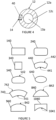
- Figure 5 shows examples of the cross-sectional profile of the pushing means 14 according to embodiments of the invention.
- the cross-section 40 of the pushing means 14 is not limited to the embodiments shown in Figure 5 .
- the cross-section 40 of the pushing means 14 may vary along the length of the pushing means 14.
- the cross-section 40 of the pushing means 14 may be substantially a rectangle 140, 240, a square 340 or an annular arc 440, 740.
- the rectangle, the square or the annular arc may have rounded corners 240, 440.
- the annular arc 440, 740 may comprise a curved side 441, 741 that conforms with a part of the circumference of the internal bore 13a of the tapered component 12.
- the annular arc 40d, 40g may comprise a curved side 442, 742 that conforms with a part of the circumference of the outer surface of the proximal end 12a of the tapered component 12.
- the cross-section 40 of the pushing means 14 may be substantially an ellipse or an oval 640.
- the cross-section 40 of the pushing means 14 may comprise a circular segment 840.
- the curved side 842 of the circular segment 840 may conform with a part of the circumference of the outer surface of the proximal end 12a of the tapered component 12.
- the cross-section 40 may be a semi-circular.
- the cross-section 40 of pushing means 14 may be an oblong-like shape 540, 940, 1040 with at least one curved side 542, 942, 1041.
- the curved side 542, 942 may conform with a part of the circumference of the outer surface of the proximal end 12a of the tapered component 12.
- the curved side 1041 may conform with a part of the circumference of the internal bore 13a of the tapered component 12.
- the oblong-like shape may comprise a first and a second side where a first end each of the first and second sides are joined at right angles to opposite ends of a third side.
- the third side may be longer than the first and second sides.
- the second ends of the first and second sides may be joined to opposite ends of a fourth side where the fourth side is a curved side.
- the fourth side may be a convex or a concave curve.
- the connector 18 may releasably connect the guiding device 10 to the vascular catheter 22.
- Figures 6 and 7 show a connector 18 according to an embodiment of the invention.
- the connector 18 may be located at or towards the proximal end 10a of the guiding device 10.
- the connector 18 may be connected to the pushing means 14 rearward of the proximal end 12a of the tapered component 12.
- the connector 18 may be moveable along the pushing means so as to be engageable with vascular catheters 22 of various lengths.
- the connector 18 may releasably connect the guiding device 10 to the proximal end of the vascular catheter 22 by any suitable fixing mechanism, including but not limited to push fit and snap fit arrangements.
- the connector may be rotatably connectable to the vascular catheter 22.
- the connector 18 comprises a free-wheeling mechanism. The free-wheeling mechanism is configured to permit connection of the connector 18 to the proximal end of the vascular catheter 22 without causing rotation of the pushing means 14. Therefore, when rotating the connector 18 to connect it to the vascular catheter 22, the tapered component 12 is not rotated within the vascular catheter 22 or the blood vessel.
- Figures 6 to 8 show a non-limiting embodiment of the connector 18 according the invention.
- Figures 6 and 7 show the connector 18 in the assembled state and connected to the pushing means 14 whilst
- Figure 8 shows an exploded side-view of the connector 18.
- the connector 18 comprises a body 30, a locking tube 38 and a free-wheeling ring 24. When assembled, the body 30 and free-wheeling ring 24 form the free-wheeling mechanism.
- the body 30 comprises a bore 34 which extends through the body 30 from the proximal end 30a to the distal end 30b.
- the central axis of the bore 34 coincides with the longitudinal axis 100 of the guiding device 10.
- the body 30 has an annular rim 32.
- the rim 32 may be proximally spaced from the distal end 30b of the body 30. In alternative embodiments, the rim may be at the distal end 30b of the body 30.
- the rim 32 may be continuous or may comprise a plurality of separate raised sections.
- the body 30 comprises a shoulder 38 proximally spaced from the rim 32.
- the shoulder 38 extends circumferentially around the body 30.
- the shoulder 38 may be continuous or may comprise a plurality of separate raised sections.
- a channel 36 is formed between the rim 32 and shoulder 38.
- the channel 38 is configured to receive a portion of the free-wheeling ring 24.
- the proximal end 30a of the body 30 may comprise a thread 35 for connecting the body 30 to additional components.
- the body 30 may be a single injection moulding.
- the free-wheeling ring 24 comprises an internal cavity 25 at the distal end of the ring 24.
- the internal cavity 25 comprises a thread 26 for connecting to the proximal end of the catheter 22.
- the internal cavity 25 may comprise a female luer thread.
- the free-wheeling ring 24 comprises an aperture 27 at the proximal end of the ring 24.
- the aperture extends through the proximal wall of the free-wheeling ring 24 into the internal cavity 25.
- the aperture 27 is configured to receive the proximal end 30b of the body 30.
- the diameter of the aperture 27 is configured to form a snap-fit over the annular rim 32 and reside between the annular rim 32 and the shoulder 38.
- the diameter of the aperture 27 is smaller than the diameter of the rim 32 and the diameter of the shoulder 38.
- the proximal end 30b of the body 30 is inserted through the aperture 27 of the free-wheeling ring 24.
- the aperture 27 of the free-wheeling ring 24 is pushed over the rim 32 so that the free-wheeling ring 24 is retained within the channel 36. Therefore, in the assembled state, the free-wheeling ring 24 is axially restrained relative to the body 30 by the rim 32 and the shoulder 38 but can freely rotate around the body 30.
- the rotation axis of the free-wheeling ring 24 may be the longitudinal axis 100.
- the pushing means 14 is connected to the body 30 by the locking tube 28.
- the outer diameter of the locking tube 28 is smaller than the diameter of the bore 34 of the body 30.
- the inner diameter of the locking tube 28 is greater than the diameter of the guide wire (not shown).
- the pushing means 14 is inserted into the bore 34 of the body 30.
- the locking tube 28 is also inserted into the bore 34 of the body 30 with an adhesive to hold the locking tube 28 and the pushing means 14 securely within the body 30.
- the locking tube 28 holds the pushing means 14 at a radially offset position relative to longitudinal axis 100. This corresponds to the pushing means 14 extending from the tapered component 12 at a position radially offset form the longitudinal axis 100.
- the free-wheeling ring 24 can be rotated to connect the connector 18 to the proximal end of the vascular catheter 22. Since the free-wheeling ring 24 rotates relative to the body 30, the connection to the vascular catheter 22 does not cause the pushing means 14 to rotate. Consequently, the tapered component 12 is not rotated within the vascular catheter 22 or the blood vessel when the guiding device 10 is connected to the catheter. The connector 18, therefore, provides a secure connection between the guiding device 10 and the vascular catheter 22 whilst avoiding rotation of the tapered component 12.
- the connector 18 may be disconnected from the vascular catheter 22 and the pushing means 14 may be pulled rearwardly to withdraw the guiding device 10 from the blood vessel along the guidewire 20, leaving the vascular catheter 22 in place.
- the guiding device 10 may be used to reduce the risk of the artery spasming during the standard insertion procedure. This contrasts with certain prior art methods in which the standard guidewire must be removed and additional components inserted in order to continue advancement of a catheter once a restricted, tortuous or spastic artery is encountered.
- the guiding device 10 may be used to "rescue" a procedure where snagging or spasm are encountered and the passage of the vascular catheter 22 along the guidewire in the blood vessel may have become obstructed and further advancement of the vascular catheter 22 may be inhibited or prevented.
- the guiding device 10 may be advanced along the guidewire and through the bore of the vascular catheter 22 so that the tapered component 12 protrudes from the distal end 22b of the vascular catheter 22.
- the tapered component 12 may then dilate the blood vessel to facilitate onward advancement of the vascular catheter 22 in the blood vessel and/or reducing the pain and discomfort experienced by the patient associated with this.
- guiding devices may be used via a sheath or without a sheath, as the device may be used as an introducer for the guiding catheter and the combination may be known as a sheathless catheter and may be universal, in that it may be used with any manufacturer's catheters and guidewires.
- the tapered component 12 may have a low friction outer surface.
- a low friction interface with the blood vessel wall facilitates smoother travel of the tapered component in the blood vessel.
- any lubricious and/or hydrophilic outer surface may provide such a low friction outer surface.
- the hydrophilic outer surface may be provided by a hydrophilic coating that is applied to the tapered component 12.
- the hydrophilic outer surface may be provided by the surface topography of the tapered component 12 (e.g. a plurality of grooves, recesses or other surface features that may lend the tapered component 12 hydrophilic properties).
- the tapered component 12 may be made of any suitable material.
- the tapered component 12 comprises plastics material. Additionally or alternatively, the tapered component 12 may comprise a resilient material that may be deformable in use within the blood vessel.
- the tapered component 12 may be formed from a single material.
- the tapered component 14 has an axial length of up to 30 cm. In certain embodiments, the tapered component 14 may have an axial length between 1 cm and 30 cm, or between 14 cm and 25 cm. In certain embodiments, the tapered component 14 has an axial length of about 14 cm. The tapered component 14 may have any axial length suitable for providing it with the required flexibility.
- the tapered component 12 may have a axial length of 14 cm, with the cylindrical first section 15 having an axial length of 10 cm and an axial length of 4 cm between the distal end 12b of the tapered component and the cylindrical first section 15.
- the second section 17 may be a convex cone where the taper of the cone conforms to an arc of a circle with a radius between 2000 mm and 4000 mm.
- the third section 19 may be a concave cone where the taper of the cone conforms an arc of a circle with a radius between 2000 mm and 4000 mm.
- the maximum diameter of the tapered component 12 is less than the internal diameter of the catheter in which it is to be inserted.
- the tapered component may have a maximum diameter that is less than 3.00 mm, less than 2.7 mm, less than 2.29 mm, less than 2.0 mm, less than 1.7 mm or less than 1.35 mm.
- the maximum diameter may be less than 2.29 mm
- the maximum diameter may be less than 2.0 mm
- the maximum diameter may be less than 1.7 mm.
- “F” refers to the French Gauge system, where 1F is equivalent to a diameter of 1.3 mm.
- the apertures 13 and 29 may be sized to permit the passage therethrough of a guidewire having a diameter between about 0.5 mm and 1 mm, e.g. having a diameter of 0.46 mm (0.018"), 0.64 mm (0.025"), 0.81 mm (0.032"), 0.89 mm (0.035"), 0.97 mm (0.038”) or 1.10 mm (0.043").
- the aperture 13 may be larger than 0.36 mm (0.014") as to permit the tapered component 12 to pass over a guidewire (e.g. an angioplasty wire) having a diameter of 0.36 mm (0.014").
- the guiding device 10 may be dimensionally compatible with and be otherwise suitable for use with a range of known vascular catheters 22 and/or guidewires 20. It is preferable for a guiding device 10 of a single size to be usable with a range of vascular catheters 22 of different lengths.
- the pushing means 14 In order to be dimensionally compatible with a particular vascular catheter 22, the pushing means 14 must extend rearwardly beyond the proximal end of the vascular catheter 22 when the tapered component 12 is in a position in which it protrudes from the distal end 22b of the vascular catheter 22. In certain embodiments, the pushing means 14 may extend from the tapered component 12 by at least 60 cm, at least 70 cm, at least 80 cm, at least 90 cm or at least 100 cm.
- the pushing means 14 may be provided with one or more markers 16 (see Figure 1 ) for indicating a deployed length of the guiding device 10.
- markers may comprise visual markers and/or non-visual markers, such as radio-opaque markers (e.g. tungsten or barium).
- radio-opaque markers e.g. tungsten or barium.
- one or more of the markers may be provided at any suitable location on the guiding device 10, not limited to the pushing means 14.
- a radio-opaque marker approximately 2 mm from the distal tip may indicate the location of the distal end of the device underfluoroscopic screening.
Landscapes
- Health & Medical Sciences (AREA)
- Life Sciences & Earth Sciences (AREA)
- Heart & Thoracic Surgery (AREA)
- Biomedical Technology (AREA)
- Engineering & Computer Science (AREA)
- Anesthesiology (AREA)
- Pulmonology (AREA)
- Hematology (AREA)
- Animal Behavior & Ethology (AREA)
- General Health & Medical Sciences (AREA)
- Public Health (AREA)
- Veterinary Medicine (AREA)
- Biophysics (AREA)
- Media Introduction/Drainage Providing Device (AREA)
Applications Claiming Priority (2)
| Application Number | Priority Date | Filing Date | Title |
|---|---|---|---|
| GBGB1917184.2A GB201917184D0 (en) | 2019-11-26 | 2019-11-26 | Guiding device for a vascular catheter |
| PCT/GB2020/052985 WO2021105658A2 (en) | 2019-11-26 | 2020-11-24 | Guiding device for a vascular catheter |
Publications (2)
| Publication Number | Publication Date |
|---|---|
| EP4065205A2 EP4065205A2 (en) | 2022-10-05 |
| EP4065205B1 true EP4065205B1 (en) | 2024-08-07 |
Family
ID=69137363
Family Applications (1)
| Application Number | Title | Priority Date | Filing Date |
|---|---|---|---|
| EP20815911.1A Active EP4065205B1 (en) | 2019-11-26 | 2020-11-24 | Guiding device for a vascular catheter |
Country Status (9)
| Country | Link |
|---|---|
| US (1) | US20230001146A1 (https=) |
| EP (1) | EP4065205B1 (https=) |
| JP (1) | JP7699388B2 (https=) |
| KR (1) | KR20220106146A (https=) |
| CN (1) | CN115023258B (https=) |
| BR (1) | BR112022010211A2 (https=) |
| ES (1) | ES2986941T3 (https=) |
| GB (1) | GB201917184D0 (https=) |
| WO (1) | WO2021105658A2 (https=) |
Families Citing this family (17)
| Publication number | Priority date | Publication date | Assignee | Title |
|---|---|---|---|---|
| CN113368367B (zh) | 2016-02-24 | 2024-03-29 | 禾木(中国)生物工程有限公司 | 柔性增强的神经血管导管 |
| CN110381855B (zh) | 2017-01-06 | 2023-07-04 | 因赛普特有限责任公司 | 用于动脉瘤治疗装置的抗血栓涂层 |
| US11395665B2 (en) | 2018-05-01 | 2022-07-26 | Incept, Llc | Devices and methods for removing obstructive material, from an intravascular site |
| JP2021522885A (ja) | 2018-05-01 | 2021-09-02 | インセプト・リミテッド・ライアビリティ・カンパニーIncept,Llc | 血管内部位から閉塞性物質を除去する装置および方法 |
| WO2020010310A1 (en) | 2018-07-06 | 2020-01-09 | Imperative Care, Inc. | Sealed neurovascular extendable catheter |
| US11471582B2 (en) | 2018-07-06 | 2022-10-18 | Incept, Llc | Vacuum transfer tool for extendable catheter |
| US11766539B2 (en) | 2019-03-29 | 2023-09-26 | Incept, Llc | Enhanced flexibility neurovascular catheter |
| US11134859B2 (en) | 2019-10-15 | 2021-10-05 | Imperative Care, Inc. | Systems and methods for multivariate stroke detection |
| US12201506B2 (en) | 2019-12-18 | 2025-01-21 | Imperative Care, Inc. | Rotatable thrombus engagement tool |
| US11439799B2 (en) | 2019-12-18 | 2022-09-13 | Imperative Care, Inc. | Split dilator aspiration system |
| JP2023507553A (ja) | 2019-12-18 | 2023-02-24 | インパラティブ、ケア、インク. | 静脈血栓塞栓症を治療するための方法及びシステム |
| US11638637B2 (en) | 2019-12-18 | 2023-05-02 | Imperative Care, Inc. | Method of removing embolic material with thrombus engagement tool |
| EP4117762A4 (en) | 2020-03-10 | 2024-05-08 | Imperative Care, Inc. | NEUROVASCULAR CATHETER WITH INCREASED FLEXIBILITY |
| US20230048388A1 (en) | 2021-08-12 | 2023-02-16 | Imperative Care, Inc. | Robotically driven interventional device |
| USD1077996S1 (en) | 2021-10-18 | 2025-06-03 | Imperative Care, Inc. | Inline fluid filter |
| CN116920182A (zh) * | 2023-01-04 | 2023-10-24 | 华中科技大学同济医学院附属协和医院 | 一种经外周中心静脉置入的左心房引流管及其引导装置 |
| US12171917B1 (en) | 2024-01-08 | 2024-12-24 | Imperative Care, Inc. | Devices for blood capture and reintroduction during aspiration procedure |
Citations (2)
| Publication number | Priority date | Publication date | Assignee | Title |
|---|---|---|---|---|
| US20090264863A1 (en) * | 2008-04-22 | 2009-10-22 | Medtronic Vascular, Inc. | Articulating Tip Tetherless Catheter System |
| US20160220795A1 (en) * | 2015-02-04 | 2016-08-04 | Teleflex Medical Incorporated | Flexible tip dilator |
Family Cites Families (26)
| Publication number | Priority date | Publication date | Assignee | Title |
|---|---|---|---|---|
| JP3318921B2 (ja) * | 1995-02-21 | 2002-08-26 | ニプロ株式会社 | スタイレットおよびスタイレット用コネクター |
| US5792144A (en) * | 1997-03-31 | 1998-08-11 | Cathco, Inc. | Stent delivery catheter system |
| JP2006087643A (ja) * | 2004-09-24 | 2006-04-06 | Terumo Corp | 血管内異物吸引装置 |
| US7744585B2 (en) * | 2004-09-29 | 2010-06-29 | Boston Scientific Scimed, Inc. | Catheter with directed flow design |
| US8048032B2 (en) * | 2006-05-03 | 2011-11-01 | Vascular Solutions, Inc. | Coaxial guide catheter for interventional cardiology procedures |
| JP5221032B2 (ja) * | 2006-12-11 | 2013-06-26 | 株式会社グツドマン | 挿入補助具、カテーテル組立体及びカテーテルセット |
| US8062316B2 (en) * | 2008-04-23 | 2011-11-22 | Avinger, Inc. | Catheter system and method for boring through blocked vascular passages |
| US8465456B2 (en) * | 2008-07-31 | 2013-06-18 | Boston Scientific Scimed, Inc. | Extendable aspiration catheter |
| JP2015509030A (ja) * | 2012-01-31 | 2015-03-26 | ボストン サイエンティフィック サイムド,インコーポレイテッドBoston Scientific Scimed,Inc. | 延長型のガイドカテーテル |
| US8574170B2 (en) * | 2012-04-06 | 2013-11-05 | Covidien Lp | Guidewire |
| WO2013185148A1 (en) * | 2012-06-08 | 2013-12-12 | Normedix Llc | Coaxial guide coil for interventional cardiology procedures |
| US9486611B2 (en) * | 2012-08-17 | 2016-11-08 | Boston Scientific Scimed, Inc. | Guide extension catheter |
| CN104902950B (zh) * | 2012-09-17 | 2018-04-10 | 波士顿科学西美德公司 | 无套环导向扩展导管 |
| ES2774327T3 (es) * | 2013-03-15 | 2020-07-20 | Qxmedical Llc | Catéter de refuerzo |
| WO2015004173A1 (en) * | 2013-07-11 | 2015-01-15 | Jenavalve Technology Gmbh | Delivery system for transcatheter aortic valve implantation |
| US20150148706A1 (en) * | 2013-11-26 | 2015-05-28 | Boston Scientific Scimed, Inc. | Medical devices for accessing body lumens |
| US9820761B2 (en) * | 2014-03-21 | 2017-11-21 | Route 92 Medical, Inc. | Rapid aspiration thrombectomy system and method |
| CN105662668B (zh) * | 2016-01-14 | 2018-06-26 | 江苏大学 | 一种锥形球囊 |
| CN105919701A (zh) * | 2016-05-24 | 2016-09-07 | 江苏大学 | 一种阶梯形球囊 |
| CN114916978B (zh) * | 2017-01-20 | 2025-02-25 | 92号医疗公司 | 单操作者颅内医疗装置输送系统和使用方法 |
| JP2018130312A (ja) * | 2017-02-15 | 2018-08-23 | オリンパス株式会社 | 医療用カテーテルチューブ |
| US10478535B2 (en) * | 2017-05-24 | 2019-11-19 | Mivi Neuroscience, Inc. | Suction catheter systems for applying effective aspiration in remote vessels, especially cerebral arteries |
| CN108355226A (zh) * | 2018-01-30 | 2018-08-03 | 张利勇 | 一种用于血管介入治疗的微导管 |
| EP4039315B1 (en) * | 2018-02-14 | 2023-12-20 | Teleflex Life Sciences Limited | Guide extension catheter |
| US11491313B2 (en) * | 2018-02-20 | 2022-11-08 | Crossliner, Inc. | Guide catheter extension system with a delivery micro-catheter configured to facilitate percutaneous coronary intervention |
| CN112423824B (zh) * | 2018-05-17 | 2023-02-21 | 92号医疗公司 | 抽吸导管系统和使用方法 |
-
2019
- 2019-11-26 GB GBGB1917184.2A patent/GB201917184D0/en not_active Ceased
-
2020
- 2020-11-24 JP JP2022531066A patent/JP7699388B2/ja active Active
- 2020-11-24 BR BR112022010211A patent/BR112022010211A2/pt unknown
- 2020-11-24 EP EP20815911.1A patent/EP4065205B1/en active Active
- 2020-11-24 ES ES20815911T patent/ES2986941T3/es active Active
- 2020-11-24 CN CN202080094268.XA patent/CN115023258B/zh active Active
- 2020-11-24 US US17/779,872 patent/US20230001146A1/en active Pending
- 2020-11-24 WO PCT/GB2020/052985 patent/WO2021105658A2/en not_active Ceased
- 2020-11-24 KR KR1020227019578A patent/KR20220106146A/ko active Pending
Patent Citations (2)
| Publication number | Priority date | Publication date | Assignee | Title |
|---|---|---|---|---|
| US20090264863A1 (en) * | 2008-04-22 | 2009-10-22 | Medtronic Vascular, Inc. | Articulating Tip Tetherless Catheter System |
| US20160220795A1 (en) * | 2015-02-04 | 2016-08-04 | Teleflex Medical Incorporated | Flexible tip dilator |
Also Published As
| Publication number | Publication date |
|---|---|
| WO2021105658A2 (en) | 2021-06-03 |
| JP2023505072A (ja) | 2023-02-08 |
| ES2986941T3 (es) | 2024-11-13 |
| US20230001146A1 (en) | 2023-01-05 |
| JP7699388B2 (ja) | 2025-06-27 |
| EP4065205A2 (en) | 2022-10-05 |
| GB201917184D0 (en) | 2020-01-08 |
| BR112022010211A2 (pt) | 2022-09-06 |
| KR20220106146A (ko) | 2022-07-28 |
| CN115023258B (zh) | 2025-02-25 |
| CN115023258A (zh) | 2022-09-06 |
| WO2021105658A3 (en) | 2021-07-29 |
Similar Documents
| Publication | Publication Date | Title |
|---|---|---|
| EP4065205B1 (en) | Guiding device for a vascular catheter | |
| US20250135167A1 (en) | Intravascular delivery system and method for percutaneous coronary intervention | |
| JP6639545B2 (ja) | 進入及び追跡用迅速交換拡張器を持つ頸動脈シース並びに使用方法 | |
| US5163903A (en) | Catheter exchange system with detachable luer fitting | |
| EP3096830B1 (en) | Collapsible tip re-entry catheter | |
| US11027093B2 (en) | Slide guide catheter and methods for use thereof | |
| EP3332830B1 (en) | Guide extension catheter | |
| EP3466476B1 (en) | Guidewire fixation | |
| WO2021167653A1 (en) | Intravascular delivery system and method for percutaneous coronary intervention | |
| EP0380227A2 (en) | Catheter exchange system with detachable luer fitting | |
| JP2017209532A (ja) | 複数の並行ガイドワイヤを有する医療用ガイドワイヤシステム | |
| US20060074477A1 (en) | Self-expanding stent delivery system | |
| WO2008006111A2 (en) | Single lumen support catheter for rapid exchange and over the wire use | |
| US20240173520A1 (en) | Devices, systems, and methods for delivering catheters or other medical devices to locations within a patient's body | |
| US20240123187A1 (en) | Intravascular delivery system and method for percutaneous coronary intervention including perfusion | |
| WO2015077545A1 (en) | Drug delivery system | |
| US8777873B2 (en) | Wire guide having a rib for coil attachment | |
| US8613713B2 (en) | Wire guide having variable flexibility and method of use thereof | |
| US20240358508A1 (en) | Peelable advancer for delivery system | |
| HK1237688B (zh) | 导丝固定术 | |
| HK1237688A1 (en) | Guidewire fixation |
Legal Events
| Date | Code | Title | Description |
|---|---|---|---|
| STAA | Information on the status of an ep patent application or granted ep patent |
Free format text: STATUS: UNKNOWN |
|
| STAA | Information on the status of an ep patent application or granted ep patent |
Free format text: STATUS: THE INTERNATIONAL PUBLICATION HAS BEEN MADE |
|
| PUAI | Public reference made under article 153(3) epc to a published international application that has entered the european phase |
Free format text: ORIGINAL CODE: 0009012 |
|
| STAA | Information on the status of an ep patent application or granted ep patent |
Free format text: STATUS: REQUEST FOR EXAMINATION WAS MADE |
|
| 17P | Request for examination filed |
Effective date: 20220526 |
|
| AK | Designated contracting states |
Kind code of ref document: A2 Designated state(s): AL AT BE BG CH CY CZ DE DK EE ES FI FR GB GR HR HU IE IS IT LI LT LU LV MC MK MT NL NO PL PT RO RS SE SI SK SM TR |
|
| DAV | Request for validation of the european patent (deleted) | ||
| DAX | Request for extension of the european patent (deleted) | ||
| P01 | Opt-out of the competence of the unified patent court (upc) registered |
Effective date: 20230503 |
|
| GRAP | Despatch of communication of intention to grant a patent |
Free format text: ORIGINAL CODE: EPIDOSNIGR1 |
|
| STAA | Information on the status of an ep patent application or granted ep patent |
Free format text: STATUS: GRANT OF PATENT IS INTENDED |
|
| INTG | Intention to grant announced |
Effective date: 20231025 |
|
| GRAJ | Information related to disapproval of communication of intention to grant by the applicant or resumption of examination proceedings by the epo deleted |
Free format text: ORIGINAL CODE: EPIDOSDIGR1 |
|
| STAA | Information on the status of an ep patent application or granted ep patent |
Free format text: STATUS: REQUEST FOR EXAMINATION WAS MADE |
|
| GRAP | Despatch of communication of intention to grant a patent |
Free format text: ORIGINAL CODE: EPIDOSNIGR1 |
|
| INTC | Intention to grant announced (deleted) | ||
| STAA | Information on the status of an ep patent application or granted ep patent |
Free format text: STATUS: GRANT OF PATENT IS INTENDED |
|
| INTG | Intention to grant announced |
Effective date: 20240328 |
|
| GRAS | Grant fee paid |
Free format text: ORIGINAL CODE: EPIDOSNIGR3 |
|
| GRAA | (expected) grant |
Free format text: ORIGINAL CODE: 0009210 |
|
| STAA | Information on the status of an ep patent application or granted ep patent |
Free format text: STATUS: THE PATENT HAS BEEN GRANTED |
|
| AK | Designated contracting states |
Kind code of ref document: B1 Designated state(s): AL AT BE BG CH CY CZ DE DK EE ES FI FR GB GR HR HU IE IS IT LI LT LU LV MC MK MT NL NO PL PT RO RS SE SI SK SM TR |
|
| REG | Reference to a national code |
Ref country code: GB Ref legal event code: FG4D |
|
| REG | Reference to a national code |
Ref country code: CH Ref legal event code: EP |
|
| REG | Reference to a national code |
Ref country code: DE Ref legal event code: R096 Ref document number: 602020035453 Country of ref document: DE |
|
| REG | Reference to a national code |
Ref country code: IE Ref legal event code: FG4D |
|
| REG | Reference to a national code |
Ref country code: ES Ref legal event code: FG2A Ref document number: 2986941 Country of ref document: ES Kind code of ref document: T3 Effective date: 20241113 |
|
| REG | Reference to a national code |
Ref country code: LT Ref legal event code: MG9D |
|
| REG | Reference to a national code |
Ref country code: NL Ref legal event code: MP Effective date: 20240807 |
|
| PG25 | Lapsed in a contracting state [announced via postgrant information from national office to epo] |
Ref country code: NO Free format text: LAPSE BECAUSE OF FAILURE TO SUBMIT A TRANSLATION OF THE DESCRIPTION OR TO PAY THE FEE WITHIN THE PRESCRIBED TIME-LIMIT Effective date: 20241107 |
|
| REG | Reference to a national code |
Ref country code: AT Ref legal event code: MK05 Ref document number: 1710271 Country of ref document: AT Kind code of ref document: T Effective date: 20240807 |
|
| PG25 | Lapsed in a contracting state [announced via postgrant information from national office to epo] |
Ref country code: NL Free format text: LAPSE BECAUSE OF FAILURE TO SUBMIT A TRANSLATION OF THE DESCRIPTION OR TO PAY THE FEE WITHIN THE PRESCRIBED TIME-LIMIT Effective date: 20240807 Ref country code: FI Free format text: LAPSE BECAUSE OF FAILURE TO SUBMIT A TRANSLATION OF THE DESCRIPTION OR TO PAY THE FEE WITHIN THE PRESCRIBED TIME-LIMIT Effective date: 20240807 Ref country code: PL Free format text: LAPSE BECAUSE OF FAILURE TO SUBMIT A TRANSLATION OF THE DESCRIPTION OR TO PAY THE FEE WITHIN THE PRESCRIBED TIME-LIMIT Effective date: 20240807 Ref country code: PT Free format text: LAPSE BECAUSE OF FAILURE TO SUBMIT A TRANSLATION OF THE DESCRIPTION OR TO PAY THE FEE WITHIN THE PRESCRIBED TIME-LIMIT Effective date: 20241209 Ref country code: GR Free format text: LAPSE BECAUSE OF FAILURE TO SUBMIT A TRANSLATION OF THE DESCRIPTION OR TO PAY THE FEE WITHIN THE PRESCRIBED TIME-LIMIT Effective date: 20241108 |
|
| PG25 | Lapsed in a contracting state [announced via postgrant information from national office to epo] |
Ref country code: BG Free format text: LAPSE BECAUSE OF FAILURE TO SUBMIT A TRANSLATION OF THE DESCRIPTION OR TO PAY THE FEE WITHIN THE PRESCRIBED TIME-LIMIT Effective date: 20240807 |
|
| PG25 | Lapsed in a contracting state [announced via postgrant information from national office to epo] |
Ref country code: LV Free format text: LAPSE BECAUSE OF FAILURE TO SUBMIT A TRANSLATION OF THE DESCRIPTION OR TO PAY THE FEE WITHIN THE PRESCRIBED TIME-LIMIT Effective date: 20240807 |
|
| PG25 | Lapsed in a contracting state [announced via postgrant information from national office to epo] |
Ref country code: AT Free format text: LAPSE BECAUSE OF FAILURE TO SUBMIT A TRANSLATION OF THE DESCRIPTION OR TO PAY THE FEE WITHIN THE PRESCRIBED TIME-LIMIT Effective date: 20240807 Ref country code: IS Free format text: LAPSE BECAUSE OF FAILURE TO SUBMIT A TRANSLATION OF THE DESCRIPTION OR TO PAY THE FEE WITHIN THE PRESCRIBED TIME-LIMIT Effective date: 20241207 |
|
| PG25 | Lapsed in a contracting state [announced via postgrant information from national office to epo] |
Ref country code: HR Free format text: LAPSE BECAUSE OF FAILURE TO SUBMIT A TRANSLATION OF THE DESCRIPTION OR TO PAY THE FEE WITHIN THE PRESCRIBED TIME-LIMIT Effective date: 20240807 |
|
| PG25 | Lapsed in a contracting state [announced via postgrant information from national office to epo] |
Ref country code: RS Free format text: LAPSE BECAUSE OF FAILURE TO SUBMIT A TRANSLATION OF THE DESCRIPTION OR TO PAY THE FEE WITHIN THE PRESCRIBED TIME-LIMIT Effective date: 20241107 |
|
| PG25 | Lapsed in a contracting state [announced via postgrant information from national office to epo] |
Ref country code: RS Free format text: LAPSE BECAUSE OF FAILURE TO SUBMIT A TRANSLATION OF THE DESCRIPTION OR TO PAY THE FEE WITHIN THE PRESCRIBED TIME-LIMIT Effective date: 20241107 Ref country code: PT Free format text: LAPSE BECAUSE OF FAILURE TO SUBMIT A TRANSLATION OF THE DESCRIPTION OR TO PAY THE FEE WITHIN THE PRESCRIBED TIME-LIMIT Effective date: 20241209 Ref country code: PL Free format text: LAPSE BECAUSE OF FAILURE TO SUBMIT A TRANSLATION OF THE DESCRIPTION OR TO PAY THE FEE WITHIN THE PRESCRIBED TIME-LIMIT Effective date: 20240807 Ref country code: NO Free format text: LAPSE BECAUSE OF FAILURE TO SUBMIT A TRANSLATION OF THE DESCRIPTION OR TO PAY THE FEE WITHIN THE PRESCRIBED TIME-LIMIT Effective date: 20241107 Ref country code: NL Free format text: LAPSE BECAUSE OF FAILURE TO SUBMIT A TRANSLATION OF THE DESCRIPTION OR TO PAY THE FEE WITHIN THE PRESCRIBED TIME-LIMIT Effective date: 20240807 Ref country code: LV Free format text: LAPSE BECAUSE OF FAILURE TO SUBMIT A TRANSLATION OF THE DESCRIPTION OR TO PAY THE FEE WITHIN THE PRESCRIBED TIME-LIMIT Effective date: 20240807 Ref country code: IS Free format text: LAPSE BECAUSE OF FAILURE TO SUBMIT A TRANSLATION OF THE DESCRIPTION OR TO PAY THE FEE WITHIN THE PRESCRIBED TIME-LIMIT Effective date: 20241207 Ref country code: HR Free format text: LAPSE BECAUSE OF FAILURE TO SUBMIT A TRANSLATION OF THE DESCRIPTION OR TO PAY THE FEE WITHIN THE PRESCRIBED TIME-LIMIT Effective date: 20240807 Ref country code: GR Free format text: LAPSE BECAUSE OF FAILURE TO SUBMIT A TRANSLATION OF THE DESCRIPTION OR TO PAY THE FEE WITHIN THE PRESCRIBED TIME-LIMIT Effective date: 20241108 Ref country code: FI Free format text: LAPSE BECAUSE OF FAILURE TO SUBMIT A TRANSLATION OF THE DESCRIPTION OR TO PAY THE FEE WITHIN THE PRESCRIBED TIME-LIMIT Effective date: 20240807 Ref country code: BG Free format text: LAPSE BECAUSE OF FAILURE TO SUBMIT A TRANSLATION OF THE DESCRIPTION OR TO PAY THE FEE WITHIN THE PRESCRIBED TIME-LIMIT Effective date: 20240807 Ref country code: AT Free format text: LAPSE BECAUSE OF FAILURE TO SUBMIT A TRANSLATION OF THE DESCRIPTION OR TO PAY THE FEE WITHIN THE PRESCRIBED TIME-LIMIT Effective date: 20240807 |
|
| PG25 | Lapsed in a contracting state [announced via postgrant information from national office to epo] |
Ref country code: DK Free format text: LAPSE BECAUSE OF FAILURE TO SUBMIT A TRANSLATION OF THE DESCRIPTION OR TO PAY THE FEE WITHIN THE PRESCRIBED TIME-LIMIT Effective date: 20240807 Ref country code: SM Free format text: LAPSE BECAUSE OF FAILURE TO SUBMIT A TRANSLATION OF THE DESCRIPTION OR TO PAY THE FEE WITHIN THE PRESCRIBED TIME-LIMIT Effective date: 20240807 |
|
| PG25 | Lapsed in a contracting state [announced via postgrant information from national office to epo] |
Ref country code: EE Free format text: LAPSE BECAUSE OF FAILURE TO SUBMIT A TRANSLATION OF THE DESCRIPTION OR TO PAY THE FEE WITHIN THE PRESCRIBED TIME-LIMIT Effective date: 20240807 |
|
| PG25 | Lapsed in a contracting state [announced via postgrant information from national office to epo] |
Ref country code: CZ Free format text: LAPSE BECAUSE OF FAILURE TO SUBMIT A TRANSLATION OF THE DESCRIPTION OR TO PAY THE FEE WITHIN THE PRESCRIBED TIME-LIMIT Effective date: 20240807 |
|
| PG25 | Lapsed in a contracting state [announced via postgrant information from national office to epo] |
Ref country code: SK Free format text: LAPSE BECAUSE OF FAILURE TO SUBMIT A TRANSLATION OF THE DESCRIPTION OR TO PAY THE FEE WITHIN THE PRESCRIBED TIME-LIMIT Effective date: 20240807 |
|
| REG | Reference to a national code |
Ref country code: DE Ref legal event code: R097 Ref document number: 602020035453 Country of ref document: DE |
|
| PLBE | No opposition filed within time limit |
Free format text: ORIGINAL CODE: 0009261 |
|
| STAA | Information on the status of an ep patent application or granted ep patent |
Free format text: STATUS: NO OPPOSITION FILED WITHIN TIME LIMIT |
|
| REG | Reference to a national code |
Ref country code: CH Ref legal event code: PL |
|
| PG25 | Lapsed in a contracting state [announced via postgrant information from national office to epo] |
Ref country code: MC Free format text: LAPSE BECAUSE OF FAILURE TO SUBMIT A TRANSLATION OF THE DESCRIPTION OR TO PAY THE FEE WITHIN THE PRESCRIBED TIME-LIMIT Effective date: 20240807 |
|
| PG25 | Lapsed in a contracting state [announced via postgrant information from national office to epo] |
Ref country code: LU Free format text: LAPSE BECAUSE OF NON-PAYMENT OF DUE FEES Effective date: 20241124 |
|
| REG | Reference to a national code |
Ref country code: CH Ref legal event code: PL |
|
| 26N | No opposition filed |
Effective date: 20250508 |
|
| PG25 | Lapsed in a contracting state [announced via postgrant information from national office to epo] |
Ref country code: CH Free format text: LAPSE BECAUSE OF NON-PAYMENT OF DUE FEES Effective date: 20241130 |
|
| REG | Reference to a national code |
Ref country code: BE Ref legal event code: MM Effective date: 20241130 |
|
| PG25 | Lapsed in a contracting state [announced via postgrant information from national office to epo] |
Ref country code: SE Free format text: LAPSE BECAUSE OF FAILURE TO SUBMIT A TRANSLATION OF THE DESCRIPTION OR TO PAY THE FEE WITHIN THE PRESCRIBED TIME-LIMIT Effective date: 20240807 |
|
| PG25 | Lapsed in a contracting state [announced via postgrant information from national office to epo] |
Ref country code: BE Free format text: LAPSE BECAUSE OF NON-PAYMENT OF DUE FEES Effective date: 20241130 |
|
| PG25 | Lapsed in a contracting state [announced via postgrant information from national office to epo] |
Ref country code: IE Free format text: LAPSE BECAUSE OF NON-PAYMENT OF DUE FEES Effective date: 20241124 |
|
| PG25 | Lapsed in a contracting state [announced via postgrant information from national office to epo] |
Ref country code: RO Free format text: LAPSE BECAUSE OF FAILURE TO SUBMIT A TRANSLATION OF THE DESCRIPTION OR TO PAY THE FEE WITHIN THE PRESCRIBED TIME-LIMIT Effective date: 20240807 |
|
| PGFP | Annual fee paid to national office [announced via postgrant information from national office to epo] |
Ref country code: DE Payment date: 20251113 Year of fee payment: 6 |
|
| PGFP | Annual fee paid to national office [announced via postgrant information from national office to epo] |
Ref country code: GB Payment date: 20251028 Year of fee payment: 6 |
|
| PGFP | Annual fee paid to national office [announced via postgrant information from national office to epo] |
Ref country code: IT Payment date: 20251113 Year of fee payment: 6 |
|
| PGFP | Annual fee paid to national office [announced via postgrant information from national office to epo] |
Ref country code: FR Payment date: 20251121 Year of fee payment: 6 |
|
| PGFP | Annual fee paid to national office [announced via postgrant information from national office to epo] |
Ref country code: ES Payment date: 20251211 Year of fee payment: 6 |
|
| PG25 | Lapsed in a contracting state [announced via postgrant information from national office to epo] |
Ref country code: HU Free format text: LAPSE BECAUSE OF FAILURE TO SUBMIT A TRANSLATION OF THE DESCRIPTION OR TO PAY THE FEE WITHIN THE PRESCRIBED TIME-LIMIT; INVALID AB INITIO Effective date: 20201124 |
|
| PG25 | Lapsed in a contracting state [announced via postgrant information from national office to epo] |
Ref country code: CY Free format text: LAPSE BECAUSE OF FAILURE TO SUBMIT A TRANSLATION OF THE DESCRIPTION OR TO PAY THE FEE WITHIN THE PRESCRIBED TIME-LIMIT; INVALID AB INITIO Effective date: 20201124 |