EP4058640B1 - Régulateur de jet - Google Patents
Régulateur de jet Download PDFInfo
- Publication number
- EP4058640B1 EP4058640B1 EP20807008.6A EP20807008A EP4058640B1 EP 4058640 B1 EP4058640 B1 EP 4058640B1 EP 20807008 A EP20807008 A EP 20807008A EP 4058640 B1 EP4058640 B1 EP 4058640B1
- Authority
- EP
- European Patent Office
- Prior art keywords
- hole
- ring
- holes
- opening cross
- jet regulator
- Prior art date
- Legal status (The legal status is an assumption and is not a legal conclusion. Google has not performed a legal analysis and makes no representation as to the accuracy of the status listed.)
- Active
Links
Images

Classifications
-
- E—FIXED CONSTRUCTIONS
- E03—WATER SUPPLY; SEWERAGE
- E03C—DOMESTIC PLUMBING INSTALLATIONS FOR FRESH WATER OR WASTE WATER; SINKS
- E03C1/00—Domestic plumbing installations for fresh water or waste water; Sinks
- E03C1/02—Plumbing installations for fresh water
- E03C1/08—Jet regulators or jet guides, e.g. anti-splash devices
- E03C1/084—Jet regulators with aerating means
Definitions
- the invention relates to a jet regulator according to the preamble of claim 1, with an outlet structure which has an outlet grid with a regular arrangement of holes and an edge which delimits the outlet grid, wherein holes of the outlet structure which are adjacent to the edge form a ring and delimit a water jet flowing through the outlet structure to the outside, wherein the ring is designed deviating from the regular arrangement.
- the arrangement of the holes and the clear opening cross-section of the holes are coordinated in such a way that individual jets passing through the holes recombine behind the outlet structure to form a common water jet.
- a sanitary fitting which has a jet regulating device inside a built-in housing, which Jet regulating device has at least one insert part which can be inserted into the installation housing and which is transverse to the Has webs oriented in the flow direction, which are limited between passage openings.
- a sanitary insert unit which has a sanitary insert part with an insert housing which has a housing inlet opening into the housing interior on an inflow-side housing front side and which is bordered by a housing peripheral edge, wherein the insert unit is assigned a screen filter which is separate from the insert housing and has a disk-shaped filter head which has an annular disk sub-region on the disk outer circumference, which is designed as a support ring which can be placed on the housing peripheral edge and which filter head has a filter structure in a central disk sub-region which is formed by webs which cross one another at intersection nodes.
- a jet regulator which can be inserted from the outlet front into the water outlet of a sanitary outlet fitting, wherein the jet regulator can be detachably secured or fixed in the water outlet and wherein at least one holding element is provided for securing or fixing the jet regulator in the water outlet, wherein the holding element passes through a passage opening provided on the circumference of the fitting housing and engages the jet regulator in a fixing manner with its end region protruding into the interior of the fitting housing.
- the jet regulator can also have a jet regulator housing with a peripheral insertion opening, wherein at least one insertion guide oriented transversely to the jet regulator longitudinal axis is provided in the housing interior of the jet regulator housing and wherein at least one preferably jet-forming insert part can be inserted into the at least one insertion guide from the insertion opening.
- the invention is based on the object of improving the jet pattern of such a jet regulator.
- the invention has also recognized that holes in the ring that are too small produce partial beams that do not fully recombine with the other, adjacent partial beams, but have a tendency to form stray beams that branch off to the side. By enlarging these holes that are too small, which entails a deviation from the uniform overall impression of the arrangement, it may be possible to reduce or even completely avoid such stray beams. The beam pattern is thus improved.
- the ring can thus be defined as the collection of all those holes of the arrangement continued over the edge that are cut off by the edge.
- the regular arrangement is formed by holes of the same size and/or the same shape.
- a regular arrangement and deviations from such an arrangement are easily recognizable.
- the enlarged hole of the ring is enlarged at the expense of at least one adjacent hole. This provides a simple formation rule for avoiding holes that are too small in the ring.
- the adjacent hole can be in the ring. This way, a difference in size between holes within the ring can be compensated.
- the adjacent hole is located inside the outlet structure. This means that holes that are too small can be moved to the inside where they do not cause any interference.
- each hole in the ring is enlarged in deviation from the regular arrangement if its clear opening cross-section would otherwise be less than half as large as the clear opening cross-section of an adjacent hole if the regular arrangement were continued.
- the advantage here is that the formation of interference rays along the entire circumference of the ring can be reduced or even avoided.
- the jet regulator can be designed as a ventilated or non-ventilated jet regulator.
- the outlet structure can, for example, have a round, oval, polygonal, in particular rectangular or square, outer contour.
- a hole of the ring is enlarged in deviation from the regular arrangement if its clear
- the hole in the ring is enlarged in a way that deviates from the regular arrangement, if its clear opening cross-section otherwise deviates from the clear opening cross-section of the adjacent hole by more than 15% if the regular arrangement is continued. This makes it possible to achieve the most even distribution of opening cross-sections possible within the ring. This promotes a particularly even design of an outer layer of the water jet and thus a particularly even jet pattern.
- the holes in the ring have clear opening cross-sections that are at most 50% larger than the clear opening cross-section of a hole inside the outlet structure.
- the holes inside the outlet structure can thus be used as a reference size. The advantage here is that the formation of holes that are too large in the ring can be avoided.
- the holes in the ring have clear opening cross-sections that are no more than 20%, and in particular no more than 15%, above the clear opening cross-section of a hole inside the outlet structure. This avoids excessive upward deviations in the clear opening cross-sections of the holes in the ring.
- the holes of the ring have clear opening cross-sections that are at or below the clear opening cross-section of a hole inside the outlet structure. This allows a particularly uniform external view of the exiting jet to be achieved.
- the mentioned surface proportions can be related to any hole, for example a median or mean value of the opening cross-sections, inside the outlet structure.
- the surface proportions are preferably related to the largest hole or an uncut hole (i.e., for example, one of the identical holes that make up the arrangement) inside the outlet structure. This allows a natural upper limit to be defined.
- the clear opening cross-sections of the holes in the ring vary by a maximum of 15%.
- the partial beams that make up an outer layer of the beam for example the aforementioned one, can be defined as being as equally large as possible. This enables the beam pattern to be as uniform as possible with as few interfering beams as possible.
- the outlet structure has at least one rotational symmetry.
- a rotational symmetry of the outlet structure for example a discrete or continuous rotational symmetry, can be transferred to the ring. This promotes a particularly uniform formation of a jet pattern.
- the outlet structure has at least a mirror symmetry.
- a mirror symmetry of the outlet structure for example a planar mirror symmetry, can be transferred to the ring. This promotes a particularly uniform formation of a jet pattern.
- the run-out structure has at least one point symmetry.
- a point symmetry of the run-out structure for example a symmetry that the run-out structure converts into itself by a point reflection at a center, can be transferred to the ring. This promotes a particularly uniform formation of a jet pattern.
- the outlet structure has a hexagonal arrangement.
- the edge can be circular.
- the invention can therefore be used with jet regulators that can be screwed onto a fitting by turning.
- the outlet structure has at least one hole in the interior, the clear opening cross-section of which is less than 50% of another hole in the ring and/or in the interior. It has been found that the formation of very small holes in the interior does not interfere with the jet pattern, so that other aspects, such as an attractive design or the desire for a characteristic marking, can be taken into account here.
- this at least one hole can be arranged in the interior of the outlet structure adjacent to the ring. It is thus possible to enlarge a hole in the ring at the expense of a hole in the interior. The arrangement can otherwise remain unchanged.
- the additional hole in the ring or inside the outlet structure can be a largest hole.
- a Absolute upper limit for the clear opening cross-sections can be specified.
- the additional hole in the ring or inside the outlet structure can be an uncut hole.
- dimensioning can be related to identical holes that make up the regular arrangement.
- a particularly small impairment of the overall appearance of the outlet structure results if the enlarged hole takes up the shape of the arrangement in at least one (edge) section.
- the continuation of the arrangement up to the edge can be made possible, for example, by the holes forming the ring having different clear opening cross-sections.
- At least one hole which is located inside the outlet structure and is adjacent to a hole in the ring, is trimmed by this hole in the ring in such a way that its (remaining) clear opening cross-section is smaller than that of the untrimmed holes in the regular arrangement.
- the invention has recognized that small holes in the interior, i.e. inside the ring, do not disrupt the jet pattern.
- the at least one hole, at the expense of which the hole in the ring was enlarged has an opening cross-section other than zero. In this way, excessive deviations from the regularity of the arrangement can be avoided.
- no hole in the ring has a clear opening cross-section that is smaller than half of the clear opening cross-section of the largest and/or uncut holes in the regular arrangement. This makes it easy to avoid beams that are too thin and/or structures that are too fine in the outlet structure.
- the hole in the interior is combined with another hole in the interior to form a larger hole.
- a shape and/or an arrangement of enlarged or trimmed holes maintains a rotational symmetry of the regular arrangement. In this way, a pleasing and/or attractive design can be achieved.
- a width of the ring is limited by a largest clear dimension of a largest and/or uncut hole in the arrangement, in particular in the interior.
- a natural scale of the outlet structure can thus be used to dimension the width, for example a dimension transverse to the direction of rotation of the ring.
- edge sections in which the holes of the ring are delimited by the edge each have a length that is at least one half of a largest clear dimension of a largest and/or uncut hole of the arrangement, in particular in the interior.
- the length of the edge sections can significantly determine the steel image because it defines an outer dimension of the outer individual beams. This allows Avoid small individual beams.
- edge sections in which the holes of the ring are delimited by the edge differ in length from one another by a maximum of 50%, preferably a maximum of 30%. This results in the most uniform external appearance possible of the emerging jet.
- edge sections in which the holes of the ring are delimited by the edge deviate in length from a largest clear dimension of a largest and/or uncut hole of the arrangement, in particular in the interior, by a maximum of 50%, preferably a maximum of 30%.
- the largest clear dimension is generally chosen based on a balance between the most efficient possible beam stabilization and the least possible beam disturbance. In this way, a dimensioning of the holes made for the interior of the beam can be transferred to the ring and thus to the outer individual beams.
- the Figures 1 to 3 show a jet regulator according to the invention, designated as a whole by 1.
- the jet regulator 1 has an inflow side 2 and an outflow side 3.
- an attachment sieve 4 is arranged, through which water flows into an interior space 32 of a housing 5.
- the jet regulator 1 may have side ventilation openings to produce an aerated water jet or may be non-ventilated.
- An outlet structure 10 is formed on the housing 5 on the downstream side 3.
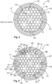
- Figure 4 shows a run-out structure 10 according to the prior art.
- the outlet structure 10 has an outlet grid 11 through which a regular arrangement 12 of holes 13 of the same size and shape is created. These holes 13 can be referred to as uncut holes. Some holes are filled in so that the regular arrangement 12 is interrupted at these points 14.
- the jet regulator 1 has a round outer contour 15 on the downstream side, which forms an edge 16 that delimits the outlet grille 11.
- This edge 16 interrupts the regular arrangement 12, and the holes 17 adjacent to the edge 16 form a circumferential ring 18.
- the ring 18 is thus designed to deviate from the regular arrangement 12 in that the edge 16 cuts off individual holes 17 of the ring 18.
- the holes 17 Due to the limitation of the regular arrangement 12, the holes 17 have different opening cross-sections, which vary from a full opening cross-section of a hole 13 to a fraction of this opening cross-section. These only partially formed holes 17 result in a deviation from the regular arrangement 12.
- the holes 17 of the ring 18 define the external appearance of the emerging water jet.
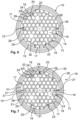
- Figure 5 shows an outlet structure 10 of a jet regulator 1 according to the invention. Functionally or constructively to the
- the hole 19 in the ring 18 is enlarged at the expense of the hole 20 in the interior 22 in order to avoid its clear opening cross-section 21 being less than half as large as a clear opening cross-section, for example of the adjacent hole 17 in the ring 18, if the hole 20 had the full hexagonal shape of the - here exemplary hexagonal - regular arrangement 12.
- the regular continuation of the regular arrangement 12 is indicated by dashed hexagons 24.
- the distribution of the clear opening cross-sections over the outlet structure 10 is as homogeneous as possible with deviations of less than 15% from a median or mean value or a largest hole 26 in the interior 22.
- the outlet structure 10 in Figure 5 has a sixfold rotational symmetry around the center, a point symmetry with respect to point reflections at the center, and three mirror symmetries on lines through the center.
- Figure 6 shows an outlet structure 10 of another jet regulator according to the invention.
- Components and functional units that are functionally and/or structurally similar or identical to the preceding embodiments are designated with the same reference numerals and are not described separately again. The statements on the preceding figures therefore apply to Figure 6 accordingly.
- the holes 19 in the ring 18 are significantly enlarged, but are still below the clear opening cross-section the largest holes 26.
- Figure 7 shows an outlet structure 10 of another jet regulator according to the invention.
- Components and functional units that are functionally and/or structurally similar or identical to the preceding embodiments are designated with the same reference numerals and are not described separately again. The statements on the preceding figures therefore apply to Figure 7 accordingly.
- Figure 7 represents a combination of the examples according to the Figures 5 and 6 represents.
- the clear opening cross-section of the holes 19 does not exceed 1.5 times the opening cross-section of the largest holes 26 in the interior.
- the outlet structure 10 has at least one hole 20 in the interior 22, which is adjacent to the ring 18 and whose clear opening cross section is less than 50% of another hole 28 in the ring 18 and of a largest hole 26 in the interior 22.
- the holes 17, 19, 25 forming the ring 18 have different clearances Opening cross-sections 21.
- no hole 19 of the ring 18 has a clear opening cross-section 21 which is smaller than one half of a clear opening cross-section of the uncut holes 13 of the regular arrangement 12.
- a width 30 of the ring 18, i.e. a dimension transverse to the direction of rotation of the ring 18, is limited by a largest clear dimension of a largest and (uncut) hole 13 of the regular arrangement 12 in the interior 22.
- edge sections 31 deviate in their length from each other and from a largest clear dimension of an uncut hole 13 of the regular arrangement 12 in the interior 22 by a maximum of 50%, here even by a maximum of 30%.
- the holes 19 are enlarged at the expense of an adjacent hole in the ring.
Landscapes
- Health & Medical Sciences (AREA)
- Life Sciences & Earth Sciences (AREA)
- Engineering & Computer Science (AREA)
- Hydrology & Water Resources (AREA)
- Public Health (AREA)
- Water Supply & Treatment (AREA)
- Nozzles (AREA)
Claims (15)
- Régulateur de jet (1) avec une structure de sortie (10) qui possède une crépine de sortie (11) avec une disposition régulière (12) de trous (13) de préférence non coupés et un bord (16) qui délimite la crépine de sortie (11), dans lequel des trous (17, 19, 25) de la structure de sortie (10) qui sont voisins du bord (16) forment un anneau (18) et délimitent vers l'extérieur un jet d'eau passant par la structure de sortie (10), des trous (17, 19, 25) de l'anneau (18) étant formés en s'écartant de la disposition régulière (12) par la délimitation de la disposition (12) par le bord (16), de sorte que les trous (17) de l'anneau (18) présentent différentes sections d'ouverture, caractérisé en ce que chaque trou (19) de l'anneau (18) est agrandi, en s'écartant de la disposition régulière (12), au détriment d'au moins un trou (20) voisin sur l'intérieur (22) de l'anneau (18) quand sa section d'ouverture libre (21) serait sinon de moins de la moitié d'une section d'ouverture libre (21) d'un trou (23) voisin de l'anneau (18) si la disposition régulière (12) continuait, et dans lequel au moins un trou (20) qui se trouve sur l'intérieur (22) de la structure de sortie (10) et qui est voisin d'un trou (17, 19, 25) de l'anneau (18) est coupé par ce trou (17, 19, 25) de l'anneau (18) de telle façon que sa section d'ouverture libre (21) est plus petite que celle des plus grands trous et/ou des trous non coupés (13) de la disposition régulière (12) et/ou en ce que l'au moins un trou (20) sur l'intérieur (22) au détriment duquel le trou (17, 19, 25) dans l'anneau (18) a été agrandi présente une section d'ouverture (21) différente de zéro et/ou en ce que le trou (20) au détriment duquel le trou (17, 19, 25) dans l'anneau (18) a été agrandi est réuni avec un autre trou sur l'intérieur pour former un plus grand trou.
- Régulateur de jet (1) selon la revendication 1, caractérisé en ce que la disposition régulière (12) est formée de trous (13) de préférence non coupés de même taille et/ou de même forme.
- Régulateur de jet (1) selon l'une des revendications précédentes, caractérisé en ce que l'anneau (18) est formé en s'écartant de la disposition régulière (12) en cela que le bord (16) coupe certains trous (17, 19, 25) de l'anneau (18).
- Régulateur de jet (1) selon l'une des revendications précédentes, caractérisé en ce que le trou agrandi de l'anneau (18) est agrandi au détriment d'au moins un trou (17, 19, 25) voisin, en particulier de l'anneau (18).
- Régulateur de jet (1) selon l'une des revendications précédentes, caractérisé en ce qu'un trou (17, 19, 25) de l'anneau (18) est agrandi en s'écartant de la disposition régulière (12) quand sa section d'ouverture libre (21) différerait sinon de plus de 20 %, en particulier de plus de 15 % de la section d'ouverture (21) du trou (23) voisin, si la disposition régulière (12) continuait.
- Régulateur de jet (1) selon l'une des revendications précédentes, caractérisé en ce que les trous (17, 19, 25) de l'anneau (18) ayant des sections d'ouverture libres (21) plus grandes que la section d'ouverture libre (21) d'au maximum 50 %, en particulier d'au maximum 20 % ou 15 %, en particulier égales ou inférieures à la section d'ouverture libre (21) d'un trou (13, 20, 26), en particulier d'un plus grand trou (26) et/ou d'un trou non coupé (13), se trouvent sur l'intérieur (22) de la structure de sortie (10).
- Régulateur de jet (1) selon l'une des revendications précédentes, caractérisé en ce que les sections d'ouverture libres (21) des trous (17, 19, 25) de l'anneau (18) varient au maximum de 15 %.
- Régulateur de jet (1) selon l'une des revendications précédentes, caractérisé en ce que la structure de sortie (10) présente une symétrie au moins en rotation, en miroir et/ou par points.
- Régulateur de jet (1) selon l'une des revendications précédentes, caractérisé en ce que la structure de sortie (10) comporte une disposition hexagonale et/ou en ce que le bord (16) est de forme circulaire.
- Régulateur de jet (1) selon l'une des revendications précédentes, caractérisé en ce que la structure de sortie (10) possède sur l'intérieur (22) au moins un trou (20), en particulier voisin de l'anneau (18), dont la section d'ouverture libre (21) représente moins de 50 % d'un autre trou (28) dans l'anneau (18) et/ou sur l'intérieur (22), en particulier d'un des plus grands trous ou d'un trou non coupé (13, 26).
- Régulateur de jet (1) selon l'une des revendications précédentes, caractérisé en ce qu'au moins une partie (29) du trou agrandi (19) prend une forme de la disposition régulière (12).
- Régulateur de jet (1) selon l'une des revendications précédentes, caractérisé en ce qu'aucun trou (17, 19, 25) de l'anneau (18) n'a une section d'ouverture libre (21) plus petite qu'une moitié d'une section d'ouverture libre (21) des plus grands trous et/ou des trous non coupés (13, 26) de la disposition régulière (12).
- Régulateur de jet (1) selon l'une des revendications précédentes, caractérisé en ce qu'une forme et/ou une disposition de trous agrandis ou coupés (17, 19, 25) respecte une symétrie en rotation de la disposition régulière (12).
- Régulateur de jet (1) selon l'une des revendications précédentes, caractérisé en ce qu'une largeur (30) de l'anneau (18) est délimitée par une plus grande dimension libre d'un plus grand trou et/ou d'un trou non coupé (13, 26) de la disposition régulière (12), en particulier sur l'intérieur (22).
- Régulateur de jet (1) selon l'une des revendications précédentes, caractérisé en ce que des parties de bord (31) dans lesquelles les trous (17, 19, 25) de l'anneau (18) sont délimités par le bord (16) ont chacune une longueur correspondant au moins à une moitié d'une plus grande dimension libre d'un des plus grands trous et/ou d'un trou non coupé (13) de la disposition régulière (12), en particulier sur l'intérieur (22), et/ou leurs longueurs diffèrent d'au maximum 50
%, de préférence d'au moins 30 %, entre elles et/ou par rapport à une plus grande dimension libre d'un des plus grands trous et/ou d'un trou non coupé (13, 26) de la disposition régulière (12).
Applications Claiming Priority (2)
| Application Number | Priority Date | Filing Date | Title |
|---|---|---|---|
| DE202019106347.5U DE202019106347U1 (de) | 2019-11-14 | 2019-11-14 | Strahlregler |
| PCT/EP2020/081938 WO2021094467A1 (fr) | 2019-11-14 | 2020-11-12 | Régulateur de jet |
Publications (2)
| Publication Number | Publication Date |
|---|---|
| EP4058640A1 EP4058640A1 (fr) | 2022-09-21 |
| EP4058640B1 true EP4058640B1 (fr) | 2024-08-14 |
Family
ID=73401533
Family Applications (1)
| Application Number | Title | Priority Date | Filing Date |
|---|---|---|---|
| EP20807008.6A Active EP4058640B1 (fr) | 2019-11-14 | 2020-11-12 | Régulateur de jet |
Country Status (5)
| Country | Link |
|---|---|
| US (1) | US12247376B2 (fr) |
| EP (1) | EP4058640B1 (fr) |
| CN (3) | CN114787458A (fr) |
| DE (1) | DE202019106347U1 (fr) |
| WO (1) | WO2021094467A1 (fr) |
Families Citing this family (6)
| Publication number | Priority date | Publication date | Assignee | Title |
|---|---|---|---|---|
| USD964514S1 (en) * | 2017-03-07 | 2022-09-20 | Neoperl Gmbh | Faucet stream straightener |
| USD839385S1 (en) | 2017-03-13 | 2019-01-29 | Neoperl Gmbh | Faucet stream straightener |
| DE202019106347U1 (de) * | 2019-11-14 | 2021-02-16 | Neoperl Gmbh | Strahlregler |
| USD963108S1 (en) * | 2021-03-19 | 2022-09-06 | Neoperl Gmbh | Faucet stream straightener |
| DE202022101528U1 (de) * | 2022-03-23 | 2023-06-26 | Neoperl Gmbh | Einsetzteil für einen Strahlregler |
| USD1107176S1 (en) * | 2023-08-11 | 2025-12-23 | Xiamen Water Nymph Sanitary Technology Co., Ltd. | Aerator for faucet |
Family Cites Families (24)
| Publication number | Priority date | Publication date | Assignee | Title |
|---|---|---|---|---|
| AU1926797A (en) * | 1996-10-11 | 1998-05-11 | Dieter Wildfang Gmbh | Sanitary outlet |
| DE10246334B4 (de) | 2002-10-04 | 2015-05-07 | Neoperl Gmbh | Sanitäres Einbauteil |
| DE10246333B4 (de) * | 2002-10-04 | 2008-06-19 | Neoperl Gmbh | Strahlregler |
| DE102004008594B4 (de) * | 2004-02-21 | 2015-03-19 | Neoperl Gmbh | Sanitäre Auslaufvorrichtung |
| DE102004018749B4 (de) * | 2004-04-17 | 2006-04-27 | Neoperl Gmbh | Auslaufelement für eine Sanitärarmatur |
| DE102005010550B4 (de) * | 2005-03-04 | 2007-03-22 | Neoperl Gmbh | Sanitärer Wasserauslauf |
| DE102006046245B4 (de) | 2006-09-28 | 2014-06-12 | Neoperl Gmbh | Sanitäre Auslaufarmatur mit einem Strahlregler |
| US9481986B2 (en) * | 2006-12-06 | 2016-11-01 | Neoperl Gmbh | Sanitary installation element |
| DE202007009836U1 (de) * | 2007-07-12 | 2007-09-13 | Neoperl Gmbh | Wasserauslauf für eine sanitäre Niederdruck-Auslaufarmatur |
| DE102008038727B4 (de) * | 2008-08-12 | 2010-10-28 | Neoperl Gmbh | Sanitärer Wasserauslauf |
| DE102009011345B4 (de) * | 2009-03-05 | 2013-12-05 | Neoperl Gmbh | Strahlregler |
| DE102010007871B4 (de) * | 2010-02-13 | 2015-02-05 | Neoperl Gmbh | Strahlregler |
| DE202011105376U1 (de) * | 2011-09-06 | 2012-12-10 | Neoperl Gmbh | Sanitäres Einbauteil |
| ES2793529T3 (es) * | 2011-11-25 | 2020-11-16 | Neoperl Gmbh | Regulador de chorro |
| US8708252B2 (en) * | 2011-11-28 | 2014-04-29 | Neoperl Gmbh | Sanitary installation part |
| DE202012010420U1 (de) * | 2012-11-02 | 2014-02-03 | Neoperl Gmbh | Strahlregler |
| DE202015003301U1 (de) * | 2015-05-05 | 2016-08-09 | Neoperl Gmbh | Strahlregler |
| DE202015007677U1 (de) * | 2015-11-05 | 2017-02-07 | Neoperl Gmbh | Strahlregler |
| DE202016005553U1 (de) * | 2016-09-08 | 2017-12-11 | Neoperl Gmbh | Sanitäre Einsetzeinheit |
| DE202017101435U1 (de) * | 2017-03-13 | 2018-06-14 | Neoperl Gmbh | Sanitäre Einsetzeinheit |
| DE202017105378U1 (de) * | 2017-09-06 | 2018-12-07 | Neoperl Gmbh | Strahlregler |
| DE102017120521A1 (de) * | 2017-09-06 | 2019-03-07 | Neoperl Gmbh | Strahlregler |
| DE102017128758A1 (de) | 2017-12-04 | 2019-06-06 | Neoperl Gmbh | Sanitäre Einsetzeinheit |
| DE202019106347U1 (de) * | 2019-11-14 | 2021-02-16 | Neoperl Gmbh | Strahlregler |
-
2019
- 2019-11-14 DE DE202019106347.5U patent/DE202019106347U1/de active Active
-
2020
- 2020-11-12 US US17/775,951 patent/US12247376B2/en active Active
- 2020-11-12 CN CN202080079170.7A patent/CN114787458A/zh active Pending
- 2020-11-12 WO PCT/EP2020/081938 patent/WO2021094467A1/fr not_active Ceased
- 2020-11-12 EP EP20807008.6A patent/EP4058640B1/fr active Active
- 2020-11-13 CN CN202011267519.8A patent/CN112796375B/zh active Active
- 2020-11-13 CN CN202022635926.1U patent/CN215367591U/zh not_active Withdrawn - After Issue
Also Published As
| Publication number | Publication date |
|---|---|
| EP4058640A1 (fr) | 2022-09-21 |
| US20220381014A1 (en) | 2022-12-01 |
| DE202019106347U1 (de) | 2021-02-16 |
| CN112796375A (zh) | 2021-05-14 |
| WO2021094467A1 (fr) | 2021-05-20 |
| CN112796375B (zh) | 2022-10-11 |
| CN114787458A (zh) | 2022-07-22 |
| US12247376B2 (en) | 2025-03-11 |
| CN215367591U (zh) | 2021-12-31 |
Similar Documents
| Publication | Publication Date | Title |
|---|---|---|
| EP4058640B1 (fr) | Régulateur de jet | |
| EP3679197B1 (fr) | Régulateur de jet | |
| EP3596277B1 (fr) | Unité d'insertion sanitaire | |
| EP0931198B1 (fr) | Regulateur de jet | |
| EP2971385B1 (fr) | Regulateur de debit ayant un deflecteur avec parois anneaux | |
| DE102013004076A1 (de) | Strahlregler mit Prallfläche und Ringwandung | |
| DE202017105378U1 (de) | Strahlregler | |
| EP3848518A1 (fr) | Unité d'écoulement sanitaire | |
| EP4111006B1 (fr) | Aérateur dans lequel des pièces sont verrouillées en rotation | |
| EP3624920B1 (fr) | Filtre à vapeur | |
| EP4077821B1 (fr) | Aérateur | |
| EP3300807B1 (fr) | Dispositif d'étranglement de l'écoulement et douche sanitaire | |
| EP3935230B1 (fr) | Brise-jet | |
| DE10149335B4 (de) | Strahlreger für eine sanitäre Auslaufarmatur | |
| DE102004008594A1 (de) | Sanitäre Auslaufvorrichtung | |
| DE4413060C2 (de) | Strahlregler | |
| DE102017120521A1 (de) | Strahlregler | |
| DE9214369U1 (de) | Drallauslaß | |
| DE4333714C2 (de) | Strahlregler zum Anschluß an Sanitärarmaturen | |
| DE102020105462A1 (de) | Sanitäre Auslaufeinheit | |
| DE102019130734A1 (de) | Strahlregler | |
| AT209818B (de) | Vorrichtung zum Belüften von unter Druck fließendem Wasser | |
| EP1123742B2 (fr) | Pomme de douche | |
| DE3416731C1 (de) | Duese zur Entlueftung von Kernblas- oder Kernschiesskaesten | |
| DE102017120517A1 (de) | Strahlregler |
Legal Events
| Date | Code | Title | Description |
|---|---|---|---|
| STAA | Information on the status of an ep patent application or granted ep patent |
Free format text: STATUS: UNKNOWN |
|
| STAA | Information on the status of an ep patent application or granted ep patent |
Free format text: STATUS: THE INTERNATIONAL PUBLICATION HAS BEEN MADE |
|
| PUAI | Public reference made under article 153(3) epc to a published international application that has entered the european phase |
Free format text: ORIGINAL CODE: 0009012 |
|
| STAA | Information on the status of an ep patent application or granted ep patent |
Free format text: STATUS: REQUEST FOR EXAMINATION WAS MADE |
|
| 17P | Request for examination filed |
Effective date: 20220614 |
|
| AK | Designated contracting states |
Kind code of ref document: A1 Designated state(s): AL AT BE BG CH CY CZ DE DK EE ES FI FR GB GR HR HU IE IS IT LI LT LU LV MC MK MT NL NO PL PT RO RS SE SI SK SM TR |
|
| DAV | Request for validation of the european patent (deleted) | ||
| DAX | Request for extension of the european patent (deleted) | ||
| GRAP | Despatch of communication of intention to grant a patent |
Free format text: ORIGINAL CODE: EPIDOSNIGR1 |
|
| STAA | Information on the status of an ep patent application or granted ep patent |
Free format text: STATUS: GRANT OF PATENT IS INTENDED |
|
| INTG | Intention to grant announced |
Effective date: 20240410 |
|
| GRAS | Grant fee paid |
Free format text: ORIGINAL CODE: EPIDOSNIGR3 |
|
| GRAA | (expected) grant |
Free format text: ORIGINAL CODE: 0009210 |
|
| STAA | Information on the status of an ep patent application or granted ep patent |
Free format text: STATUS: THE PATENT HAS BEEN GRANTED |
|
| AK | Designated contracting states |
Kind code of ref document: B1 Designated state(s): AL AT BE BG CH CY CZ DE DK EE ES FI FR GB GR HR HU IE IS IT LI LT LU LV MC MK MT NL NO PL PT RO RS SE SI SK SM TR |
|
| REG | Reference to a national code |
Ref country code: GB Ref legal event code: FG4D Free format text: NOT ENGLISH |
|
| REG | Reference to a national code |
Ref country code: CH Ref legal event code: EP |
|
| REG | Reference to a national code |
Ref country code: DE Ref legal event code: R096 Ref document number: 502020008897 Country of ref document: DE |
|
| REG | Reference to a national code |
Ref country code: IE Ref legal event code: FG4D Free format text: LANGUAGE OF EP DOCUMENT: GERMAN |
|
| REG | Reference to a national code |
Ref country code: LT Ref legal event code: MG9D |
|
| REG | Reference to a national code |
Ref country code: NL Ref legal event code: MP Effective date: 20240814 |
|
| PGFP | Annual fee paid to national office [announced via postgrant information from national office to epo] |
Ref country code: DE Payment date: 20241213 Year of fee payment: 5 |
|
| PG25 | Lapsed in a contracting state [announced via postgrant information from national office to epo] |
Ref country code: NO Free format text: LAPSE BECAUSE OF FAILURE TO SUBMIT A TRANSLATION OF THE DESCRIPTION OR TO PAY THE FEE WITHIN THE PRESCRIBED TIME-LIMIT Effective date: 20241114 |
|
| PG25 | Lapsed in a contracting state [announced via postgrant information from national office to epo] |
Ref country code: FI Free format text: LAPSE BECAUSE OF FAILURE TO SUBMIT A TRANSLATION OF THE DESCRIPTION OR TO PAY THE FEE WITHIN THE PRESCRIBED TIME-LIMIT Effective date: 20240814 Ref country code: NL Free format text: LAPSE BECAUSE OF FAILURE TO SUBMIT A TRANSLATION OF THE DESCRIPTION OR TO PAY THE FEE WITHIN THE PRESCRIBED TIME-LIMIT Effective date: 20240814 Ref country code: GR Free format text: LAPSE BECAUSE OF FAILURE TO SUBMIT A TRANSLATION OF THE DESCRIPTION OR TO PAY THE FEE WITHIN THE PRESCRIBED TIME-LIMIT Effective date: 20241115 Ref country code: PL Free format text: LAPSE BECAUSE OF FAILURE TO SUBMIT A TRANSLATION OF THE DESCRIPTION OR TO PAY THE FEE WITHIN THE PRESCRIBED TIME-LIMIT Effective date: 20240814 Ref country code: PT Free format text: LAPSE BECAUSE OF FAILURE TO SUBMIT A TRANSLATION OF THE DESCRIPTION OR TO PAY THE FEE WITHIN THE PRESCRIBED TIME-LIMIT Effective date: 20241216 |
|
| PG25 | Lapsed in a contracting state [announced via postgrant information from national office to epo] |
Ref country code: BG Free format text: LAPSE BECAUSE OF FAILURE TO SUBMIT A TRANSLATION OF THE DESCRIPTION OR TO PAY THE FEE WITHIN THE PRESCRIBED TIME-LIMIT Effective date: 20240814 |
|
| PG25 | Lapsed in a contracting state [announced via postgrant information from national office to epo] |
Ref country code: LV Free format text: LAPSE BECAUSE OF FAILURE TO SUBMIT A TRANSLATION OF THE DESCRIPTION OR TO PAY THE FEE WITHIN THE PRESCRIBED TIME-LIMIT Effective date: 20240814 |
|
| PG25 | Lapsed in a contracting state [announced via postgrant information from national office to epo] |
Ref country code: IS Free format text: LAPSE BECAUSE OF FAILURE TO SUBMIT A TRANSLATION OF THE DESCRIPTION OR TO PAY THE FEE WITHIN THE PRESCRIBED TIME-LIMIT Effective date: 20241214 |
|
| PG25 | Lapsed in a contracting state [announced via postgrant information from national office to epo] |
Ref country code: HR Free format text: LAPSE BECAUSE OF FAILURE TO SUBMIT A TRANSLATION OF THE DESCRIPTION OR TO PAY THE FEE WITHIN THE PRESCRIBED TIME-LIMIT Effective date: 20240814 |
|
| PG25 | Lapsed in a contracting state [announced via postgrant information from national office to epo] |
Ref country code: RS Free format text: LAPSE BECAUSE OF FAILURE TO SUBMIT A TRANSLATION OF THE DESCRIPTION OR TO PAY THE FEE WITHIN THE PRESCRIBED TIME-LIMIT Effective date: 20241114 Ref country code: ES Free format text: LAPSE BECAUSE OF FAILURE TO SUBMIT A TRANSLATION OF THE DESCRIPTION OR TO PAY THE FEE WITHIN THE PRESCRIBED TIME-LIMIT Effective date: 20240814 |
|
| PG25 | Lapsed in a contracting state [announced via postgrant information from national office to epo] |
Ref country code: RS Free format text: LAPSE BECAUSE OF FAILURE TO SUBMIT A TRANSLATION OF THE DESCRIPTION OR TO PAY THE FEE WITHIN THE PRESCRIBED TIME-LIMIT Effective date: 20241114 Ref country code: PT Free format text: LAPSE BECAUSE OF FAILURE TO SUBMIT A TRANSLATION OF THE DESCRIPTION OR TO PAY THE FEE WITHIN THE PRESCRIBED TIME-LIMIT Effective date: 20241216 Ref country code: PL Free format text: LAPSE BECAUSE OF FAILURE TO SUBMIT A TRANSLATION OF THE DESCRIPTION OR TO PAY THE FEE WITHIN THE PRESCRIBED TIME-LIMIT Effective date: 20240814 Ref country code: NO Free format text: LAPSE BECAUSE OF FAILURE TO SUBMIT A TRANSLATION OF THE DESCRIPTION OR TO PAY THE FEE WITHIN THE PRESCRIBED TIME-LIMIT Effective date: 20241114 Ref country code: NL Free format text: LAPSE BECAUSE OF FAILURE TO SUBMIT A TRANSLATION OF THE DESCRIPTION OR TO PAY THE FEE WITHIN THE PRESCRIBED TIME-LIMIT Effective date: 20240814 Ref country code: LV Free format text: LAPSE BECAUSE OF FAILURE TO SUBMIT A TRANSLATION OF THE DESCRIPTION OR TO PAY THE FEE WITHIN THE PRESCRIBED TIME-LIMIT Effective date: 20240814 Ref country code: IS Free format text: LAPSE BECAUSE OF FAILURE TO SUBMIT A TRANSLATION OF THE DESCRIPTION OR TO PAY THE FEE WITHIN THE PRESCRIBED TIME-LIMIT Effective date: 20241214 Ref country code: HR Free format text: LAPSE BECAUSE OF FAILURE TO SUBMIT A TRANSLATION OF THE DESCRIPTION OR TO PAY THE FEE WITHIN THE PRESCRIBED TIME-LIMIT Effective date: 20240814 Ref country code: GR Free format text: LAPSE BECAUSE OF FAILURE TO SUBMIT A TRANSLATION OF THE DESCRIPTION OR TO PAY THE FEE WITHIN THE PRESCRIBED TIME-LIMIT Effective date: 20241115 Ref country code: FI Free format text: LAPSE BECAUSE OF FAILURE TO SUBMIT A TRANSLATION OF THE DESCRIPTION OR TO PAY THE FEE WITHIN THE PRESCRIBED TIME-LIMIT Effective date: 20240814 Ref country code: ES Free format text: LAPSE BECAUSE OF FAILURE TO SUBMIT A TRANSLATION OF THE DESCRIPTION OR TO PAY THE FEE WITHIN THE PRESCRIBED TIME-LIMIT Effective date: 20240814 Ref country code: BG Free format text: LAPSE BECAUSE OF FAILURE TO SUBMIT A TRANSLATION OF THE DESCRIPTION OR TO PAY THE FEE WITHIN THE PRESCRIBED TIME-LIMIT Effective date: 20240814 |
|
| PG25 | Lapsed in a contracting state [announced via postgrant information from national office to epo] |
Ref country code: SM Free format text: LAPSE BECAUSE OF FAILURE TO SUBMIT A TRANSLATION OF THE DESCRIPTION OR TO PAY THE FEE WITHIN THE PRESCRIBED TIME-LIMIT Effective date: 20240814 Ref country code: DK Free format text: LAPSE BECAUSE OF FAILURE TO SUBMIT A TRANSLATION OF THE DESCRIPTION OR TO PAY THE FEE WITHIN THE PRESCRIBED TIME-LIMIT Effective date: 20240814 Ref country code: RO Free format text: LAPSE BECAUSE OF FAILURE TO SUBMIT A TRANSLATION OF THE DESCRIPTION OR TO PAY THE FEE WITHIN THE PRESCRIBED TIME-LIMIT Effective date: 20240814 |
|
| PG25 | Lapsed in a contracting state [announced via postgrant information from national office to epo] |
Ref country code: EE Free format text: LAPSE BECAUSE OF FAILURE TO SUBMIT A TRANSLATION OF THE DESCRIPTION OR TO PAY THE FEE WITHIN THE PRESCRIBED TIME-LIMIT Effective date: 20240814 |
|
| PG25 | Lapsed in a contracting state [announced via postgrant information from national office to epo] |
Ref country code: CZ Free format text: LAPSE BECAUSE OF FAILURE TO SUBMIT A TRANSLATION OF THE DESCRIPTION OR TO PAY THE FEE WITHIN THE PRESCRIBED TIME-LIMIT Effective date: 20240814 |
|
| PG25 | Lapsed in a contracting state [announced via postgrant information from national office to epo] |
Ref country code: IT Free format text: LAPSE BECAUSE OF FAILURE TO SUBMIT A TRANSLATION OF THE DESCRIPTION OR TO PAY THE FEE WITHIN THE PRESCRIBED TIME-LIMIT Effective date: 20240814 Ref country code: SK Free format text: LAPSE BECAUSE OF FAILURE TO SUBMIT A TRANSLATION OF THE DESCRIPTION OR TO PAY THE FEE WITHIN THE PRESCRIBED TIME-LIMIT Effective date: 20240814 |
|
| REG | Reference to a national code |
Ref country code: DE Ref legal event code: R097 Ref document number: 502020008897 Country of ref document: DE |
|
| PLBE | No opposition filed within time limit |
Free format text: ORIGINAL CODE: 0009261 |
|
| STAA | Information on the status of an ep patent application or granted ep patent |
Free format text: STATUS: NO OPPOSITION FILED WITHIN TIME LIMIT |
|
| REG | Reference to a national code |
Ref country code: CH Ref legal event code: PL |
|
| PG25 | Lapsed in a contracting state [announced via postgrant information from national office to epo] |
Ref country code: MC Free format text: LAPSE BECAUSE OF FAILURE TO SUBMIT A TRANSLATION OF THE DESCRIPTION OR TO PAY THE FEE WITHIN THE PRESCRIBED TIME-LIMIT Effective date: 20240814 |
|
| PG25 | Lapsed in a contracting state [announced via postgrant information from national office to epo] |
Ref country code: LU Free format text: LAPSE BECAUSE OF NON-PAYMENT OF DUE FEES Effective date: 20241112 |
|
| REG | Reference to a national code |
Ref country code: CH Ref legal event code: PL |
|
| 26N | No opposition filed |
Effective date: 20250515 |
|
| GBPC | Gb: european patent ceased through non-payment of renewal fee |
Effective date: 20241114 |
|
| PG25 | Lapsed in a contracting state [announced via postgrant information from national office to epo] |
Ref country code: CH Free format text: LAPSE BECAUSE OF NON-PAYMENT OF DUE FEES Effective date: 20241130 |
|
| REG | Reference to a national code |
Ref country code: BE Ref legal event code: MM Effective date: 20241130 |
|
| PG25 | Lapsed in a contracting state [announced via postgrant information from national office to epo] |
Ref country code: SE Free format text: LAPSE BECAUSE OF FAILURE TO SUBMIT A TRANSLATION OF THE DESCRIPTION OR TO PAY THE FEE WITHIN THE PRESCRIBED TIME-LIMIT Effective date: 20240814 |
|
| PG25 | Lapsed in a contracting state [announced via postgrant information from national office to epo] |
Ref country code: BE Free format text: LAPSE BECAUSE OF NON-PAYMENT OF DUE FEES Effective date: 20241130 Ref country code: GB Free format text: LAPSE BECAUSE OF NON-PAYMENT OF DUE FEES Effective date: 20241114 |
|
| PG25 | Lapsed in a contracting state [announced via postgrant information from national office to epo] |
Ref country code: FR Free format text: LAPSE BECAUSE OF NON-PAYMENT OF DUE FEES Effective date: 20241130 |
|
| PG25 | Lapsed in a contracting state [announced via postgrant information from national office to epo] |
Ref country code: IE Free format text: LAPSE BECAUSE OF NON-PAYMENT OF DUE FEES Effective date: 20241112 |
|
| PGFP | Annual fee paid to national office [announced via postgrant information from national office to epo] |
Ref country code: AT Payment date: 20260113 Year of fee payment: 5 |
|
| PG25 | Lapsed in a contracting state [announced via postgrant information from national office to epo] |
Ref country code: HU Free format text: LAPSE BECAUSE OF FAILURE TO SUBMIT A TRANSLATION OF THE DESCRIPTION OR TO PAY THE FEE WITHIN THE PRESCRIBED TIME-LIMIT; INVALID AB INITIO Effective date: 20201112 |