EP4058640B1 - Jet regulator - Google Patents
Jet regulator Download PDFInfo
- Publication number
- EP4058640B1 EP4058640B1 EP20807008.6A EP20807008A EP4058640B1 EP 4058640 B1 EP4058640 B1 EP 4058640B1 EP 20807008 A EP20807008 A EP 20807008A EP 4058640 B1 EP4058640 B1 EP 4058640B1
- Authority
- EP
- European Patent Office
- Prior art keywords
- hole
- ring
- holes
- opening cross
- jet regulator
- Prior art date
- Legal status (The legal status is an assumption and is not a legal conclusion. Google has not performed a legal analysis and makes no representation as to the accuracy of the status listed.)
- Active
Links
Images

Classifications
-
- E—FIXED CONSTRUCTIONS
- E03—WATER SUPPLY; SEWERAGE
- E03C—DOMESTIC PLUMBING INSTALLATIONS FOR FRESH WATER OR WASTE WATER; SINKS
- E03C1/00—Domestic plumbing installations for fresh water or waste water; Sinks
- E03C1/02—Plumbing installations for fresh water
- E03C1/08—Jet regulators or jet guides, e.g. anti-splash devices
- E03C1/084—Jet regulators with aerating means
Definitions
- the invention relates to a jet regulator according to the preamble of claim 1, with an outlet structure which has an outlet grid with a regular arrangement of holes and an edge which delimits the outlet grid, wherein holes of the outlet structure which are adjacent to the edge form a ring and delimit a water jet flowing through the outlet structure to the outside, wherein the ring is designed deviating from the regular arrangement.
- the arrangement of the holes and the clear opening cross-section of the holes are coordinated in such a way that individual jets passing through the holes recombine behind the outlet structure to form a common water jet.
- a sanitary fitting which has a jet regulating device inside a built-in housing, which Jet regulating device has at least one insert part which can be inserted into the installation housing and which is transverse to the Has webs oriented in the flow direction, which are limited between passage openings.
- a sanitary insert unit which has a sanitary insert part with an insert housing which has a housing inlet opening into the housing interior on an inflow-side housing front side and which is bordered by a housing peripheral edge, wherein the insert unit is assigned a screen filter which is separate from the insert housing and has a disk-shaped filter head which has an annular disk sub-region on the disk outer circumference, which is designed as a support ring which can be placed on the housing peripheral edge and which filter head has a filter structure in a central disk sub-region which is formed by webs which cross one another at intersection nodes.
- a jet regulator which can be inserted from the outlet front into the water outlet of a sanitary outlet fitting, wherein the jet regulator can be detachably secured or fixed in the water outlet and wherein at least one holding element is provided for securing or fixing the jet regulator in the water outlet, wherein the holding element passes through a passage opening provided on the circumference of the fitting housing and engages the jet regulator in a fixing manner with its end region protruding into the interior of the fitting housing.
- the jet regulator can also have a jet regulator housing with a peripheral insertion opening, wherein at least one insertion guide oriented transversely to the jet regulator longitudinal axis is provided in the housing interior of the jet regulator housing and wherein at least one preferably jet-forming insert part can be inserted into the at least one insertion guide from the insertion opening.
- the invention is based on the object of improving the jet pattern of such a jet regulator.
- the invention has also recognized that holes in the ring that are too small produce partial beams that do not fully recombine with the other, adjacent partial beams, but have a tendency to form stray beams that branch off to the side. By enlarging these holes that are too small, which entails a deviation from the uniform overall impression of the arrangement, it may be possible to reduce or even completely avoid such stray beams. The beam pattern is thus improved.
- the ring can thus be defined as the collection of all those holes of the arrangement continued over the edge that are cut off by the edge.
- the regular arrangement is formed by holes of the same size and/or the same shape.
- a regular arrangement and deviations from such an arrangement are easily recognizable.
- the enlarged hole of the ring is enlarged at the expense of at least one adjacent hole. This provides a simple formation rule for avoiding holes that are too small in the ring.
- the adjacent hole can be in the ring. This way, a difference in size between holes within the ring can be compensated.
- the adjacent hole is located inside the outlet structure. This means that holes that are too small can be moved to the inside where they do not cause any interference.
- each hole in the ring is enlarged in deviation from the regular arrangement if its clear opening cross-section would otherwise be less than half as large as the clear opening cross-section of an adjacent hole if the regular arrangement were continued.
- the advantage here is that the formation of interference rays along the entire circumference of the ring can be reduced or even avoided.
- the jet regulator can be designed as a ventilated or non-ventilated jet regulator.
- the outlet structure can, for example, have a round, oval, polygonal, in particular rectangular or square, outer contour.
- a hole of the ring is enlarged in deviation from the regular arrangement if its clear
- the hole in the ring is enlarged in a way that deviates from the regular arrangement, if its clear opening cross-section otherwise deviates from the clear opening cross-section of the adjacent hole by more than 15% if the regular arrangement is continued. This makes it possible to achieve the most even distribution of opening cross-sections possible within the ring. This promotes a particularly even design of an outer layer of the water jet and thus a particularly even jet pattern.
- the holes in the ring have clear opening cross-sections that are at most 50% larger than the clear opening cross-section of a hole inside the outlet structure.
- the holes inside the outlet structure can thus be used as a reference size. The advantage here is that the formation of holes that are too large in the ring can be avoided.
- the holes in the ring have clear opening cross-sections that are no more than 20%, and in particular no more than 15%, above the clear opening cross-section of a hole inside the outlet structure. This avoids excessive upward deviations in the clear opening cross-sections of the holes in the ring.
- the holes of the ring have clear opening cross-sections that are at or below the clear opening cross-section of a hole inside the outlet structure. This allows a particularly uniform external view of the exiting jet to be achieved.
- the mentioned surface proportions can be related to any hole, for example a median or mean value of the opening cross-sections, inside the outlet structure.
- the surface proportions are preferably related to the largest hole or an uncut hole (i.e., for example, one of the identical holes that make up the arrangement) inside the outlet structure. This allows a natural upper limit to be defined.
- the clear opening cross-sections of the holes in the ring vary by a maximum of 15%.
- the partial beams that make up an outer layer of the beam for example the aforementioned one, can be defined as being as equally large as possible. This enables the beam pattern to be as uniform as possible with as few interfering beams as possible.
- the outlet structure has at least one rotational symmetry.
- a rotational symmetry of the outlet structure for example a discrete or continuous rotational symmetry, can be transferred to the ring. This promotes a particularly uniform formation of a jet pattern.
- the outlet structure has at least a mirror symmetry.
- a mirror symmetry of the outlet structure for example a planar mirror symmetry, can be transferred to the ring. This promotes a particularly uniform formation of a jet pattern.
- the run-out structure has at least one point symmetry.
- a point symmetry of the run-out structure for example a symmetry that the run-out structure converts into itself by a point reflection at a center, can be transferred to the ring. This promotes a particularly uniform formation of a jet pattern.
- the outlet structure has a hexagonal arrangement.
- the edge can be circular.
- the invention can therefore be used with jet regulators that can be screwed onto a fitting by turning.
- the outlet structure has at least one hole in the interior, the clear opening cross-section of which is less than 50% of another hole in the ring and/or in the interior. It has been found that the formation of very small holes in the interior does not interfere with the jet pattern, so that other aspects, such as an attractive design or the desire for a characteristic marking, can be taken into account here.
- this at least one hole can be arranged in the interior of the outlet structure adjacent to the ring. It is thus possible to enlarge a hole in the ring at the expense of a hole in the interior. The arrangement can otherwise remain unchanged.
- the additional hole in the ring or inside the outlet structure can be a largest hole.
- a Absolute upper limit for the clear opening cross-sections can be specified.
- the additional hole in the ring or inside the outlet structure can be an uncut hole.
- dimensioning can be related to identical holes that make up the regular arrangement.
- a particularly small impairment of the overall appearance of the outlet structure results if the enlarged hole takes up the shape of the arrangement in at least one (edge) section.
- the continuation of the arrangement up to the edge can be made possible, for example, by the holes forming the ring having different clear opening cross-sections.
- At least one hole which is located inside the outlet structure and is adjacent to a hole in the ring, is trimmed by this hole in the ring in such a way that its (remaining) clear opening cross-section is smaller than that of the untrimmed holes in the regular arrangement.
- the invention has recognized that small holes in the interior, i.e. inside the ring, do not disrupt the jet pattern.
- the at least one hole, at the expense of which the hole in the ring was enlarged has an opening cross-section other than zero. In this way, excessive deviations from the regularity of the arrangement can be avoided.
- no hole in the ring has a clear opening cross-section that is smaller than half of the clear opening cross-section of the largest and/or uncut holes in the regular arrangement. This makes it easy to avoid beams that are too thin and/or structures that are too fine in the outlet structure.
- the hole in the interior is combined with another hole in the interior to form a larger hole.
- a shape and/or an arrangement of enlarged or trimmed holes maintains a rotational symmetry of the regular arrangement. In this way, a pleasing and/or attractive design can be achieved.
- a width of the ring is limited by a largest clear dimension of a largest and/or uncut hole in the arrangement, in particular in the interior.
- a natural scale of the outlet structure can thus be used to dimension the width, for example a dimension transverse to the direction of rotation of the ring.
- edge sections in which the holes of the ring are delimited by the edge each have a length that is at least one half of a largest clear dimension of a largest and/or uncut hole of the arrangement, in particular in the interior.
- the length of the edge sections can significantly determine the steel image because it defines an outer dimension of the outer individual beams. This allows Avoid small individual beams.
- edge sections in which the holes of the ring are delimited by the edge differ in length from one another by a maximum of 50%, preferably a maximum of 30%. This results in the most uniform external appearance possible of the emerging jet.
- edge sections in which the holes of the ring are delimited by the edge deviate in length from a largest clear dimension of a largest and/or uncut hole of the arrangement, in particular in the interior, by a maximum of 50%, preferably a maximum of 30%.
- the largest clear dimension is generally chosen based on a balance between the most efficient possible beam stabilization and the least possible beam disturbance. In this way, a dimensioning of the holes made for the interior of the beam can be transferred to the ring and thus to the outer individual beams.
- the Figures 1 to 3 show a jet regulator according to the invention, designated as a whole by 1.
- the jet regulator 1 has an inflow side 2 and an outflow side 3.
- an attachment sieve 4 is arranged, through which water flows into an interior space 32 of a housing 5.
- the jet regulator 1 may have side ventilation openings to produce an aerated water jet or may be non-ventilated.
- An outlet structure 10 is formed on the housing 5 on the downstream side 3.
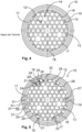
- Figure 4 shows a run-out structure 10 according to the prior art.
- the outlet structure 10 has an outlet grid 11 through which a regular arrangement 12 of holes 13 of the same size and shape is created. These holes 13 can be referred to as uncut holes. Some holes are filled in so that the regular arrangement 12 is interrupted at these points 14.
- the jet regulator 1 has a round outer contour 15 on the downstream side, which forms an edge 16 that delimits the outlet grille 11.
- This edge 16 interrupts the regular arrangement 12, and the holes 17 adjacent to the edge 16 form a circumferential ring 18.
- the ring 18 is thus designed to deviate from the regular arrangement 12 in that the edge 16 cuts off individual holes 17 of the ring 18.
- the holes 17 Due to the limitation of the regular arrangement 12, the holes 17 have different opening cross-sections, which vary from a full opening cross-section of a hole 13 to a fraction of this opening cross-section. These only partially formed holes 17 result in a deviation from the regular arrangement 12.
- the holes 17 of the ring 18 define the external appearance of the emerging water jet.
- Figure 5 shows an outlet structure 10 of a jet regulator 1 according to the invention. Functionally or constructively to the
- the hole 19 in the ring 18 is enlarged at the expense of the hole 20 in the interior 22 in order to avoid its clear opening cross-section 21 being less than half as large as a clear opening cross-section, for example of the adjacent hole 17 in the ring 18, if the hole 20 had the full hexagonal shape of the - here exemplary hexagonal - regular arrangement 12.
- the regular continuation of the regular arrangement 12 is indicated by dashed hexagons 24.
- the distribution of the clear opening cross-sections over the outlet structure 10 is as homogeneous as possible with deviations of less than 15% from a median or mean value or a largest hole 26 in the interior 22.
- the outlet structure 10 in Figure 5 has a sixfold rotational symmetry around the center, a point symmetry with respect to point reflections at the center, and three mirror symmetries on lines through the center.
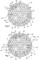
- Figure 6 shows an outlet structure 10 of another jet regulator according to the invention.
- Components and functional units that are functionally and/or structurally similar or identical to the preceding embodiments are designated with the same reference numerals and are not described separately again. The statements on the preceding figures therefore apply to Figure 6 accordingly.
- the holes 19 in the ring 18 are significantly enlarged, but are still below the clear opening cross-section the largest holes 26.
- Figure 7 shows an outlet structure 10 of another jet regulator according to the invention.
- Components and functional units that are functionally and/or structurally similar or identical to the preceding embodiments are designated with the same reference numerals and are not described separately again. The statements on the preceding figures therefore apply to Figure 7 accordingly.
- Figure 7 represents a combination of the examples according to the Figures 5 and 6 represents.
- the clear opening cross-section of the holes 19 does not exceed 1.5 times the opening cross-section of the largest holes 26 in the interior.
- the outlet structure 10 has at least one hole 20 in the interior 22, which is adjacent to the ring 18 and whose clear opening cross section is less than 50% of another hole 28 in the ring 18 and of a largest hole 26 in the interior 22.
- the holes 17, 19, 25 forming the ring 18 have different clearances Opening cross-sections 21.
- no hole 19 of the ring 18 has a clear opening cross-section 21 which is smaller than one half of a clear opening cross-section of the uncut holes 13 of the regular arrangement 12.
- a width 30 of the ring 18, i.e. a dimension transverse to the direction of rotation of the ring 18, is limited by a largest clear dimension of a largest and (uncut) hole 13 of the regular arrangement 12 in the interior 22.
- edge sections 31 deviate in their length from each other and from a largest clear dimension of an uncut hole 13 of the regular arrangement 12 in the interior 22 by a maximum of 50%, here even by a maximum of 30%.
- the holes 19 are enlarged at the expense of an adjacent hole in the ring.
Landscapes
- Health & Medical Sciences (AREA)
- Life Sciences & Earth Sciences (AREA)
- Engineering & Computer Science (AREA)
- Hydrology & Water Resources (AREA)
- Public Health (AREA)
- Water Supply & Treatment (AREA)
- Nozzles (AREA)
Description
Die Erfindung betrifft einen Strahlregler gemäss dem Oberbegriff von Anspruch 1, mit einer Auslaufstruktur, die ein Auslaufgitter mit einer regelmäßigen Anordnung von Löchern und einen Rand, der das Auslaufgitter begrenzt, hat, wobei Löcher der Auslaufstruktur, die zu dem Rand benachbart sind, einen Ring formen und einen durch die Auslaufstruktur strömenden Wasserstrahl nach außen begrenzen, wobei der Ring abweichend von der regelmäßigen Anordnung ausgebildet ist.The invention relates to a jet regulator according to the preamble of claim 1, with an outlet structure which has an outlet grid with a regular arrangement of holes and an edge which delimits the outlet grid, wherein holes of the outlet structure which are adjacent to the edge form a ring and delimit a water jet flowing through the outlet structure to the outside, wherein the ring is designed deviating from the regular arrangement.
Derartige Strahlregler sind bekannt und werden mittlerweile aus Kunststoff in Spritzgusstechnik hergestellt. Hierbei ist es üblich geworden, die Auslaufstruktur mit einer regelmäßigen Anordnung von Löchern, beispielsweise einer hexagonalen Anordnung von sechseckigen Löchern, zu versehen, um dasSuch jet regulators are well known and are now made of plastic using injection molding technology. It has become common practice to provide the outlet structure with a regular arrangement of holes, for example a hexagonal arrangement of hexagonal holes, in order to
Strahlbild gleichmäßig zu formen. Diese regelmäßige Anordnung findet ihre Grenze in den Abmessungen des Strahlreglers, der beispielsweise eine runde oder eine rechteckige oder eine sonstige, von der Anordnung abweichende Außenkontur haben kann.To form a uniform jet pattern. This regular arrangement is limited by the dimensions of the jet regulator, which can have a round or rectangular or other external contour that differs from the arrangement.
Die Anordnung der Löcher und ein lichter Öffnungsquerschnitt der Löcher sind hierbei so aufeinander abgestimmt, dass Einzelstrahlen, die durch die Löcher hindurchtreten, hinter der Auslaufstruktur zu einem gemeinsamen Wasserstrahl rekombinieren.The arrangement of the holes and the clear opening cross-section of the holes are coordinated in such a way that individual jets passing through the holes recombine behind the outlet structure to form a common water jet.
Aus
Strahlreguliereinrichtung zumindest ein, in das Einbau-Gehäuse einsetzbares Einsetzteil aufweist, das quer zur Durchströmungsrichtung orientierte Stege hat, die zwischen Durchtrittsöffnungen begrenzt sind.Out of
Jet regulating device has at least one insert part which can be inserted into the installation housing and which is transverse to the Has webs oriented in the flow direction, which are limited between passage openings.
Aus
Aus
Der Strahlregler kann auch ein Strahlreglergehäuse mit einer umfangsseitigen Einschuböffnung haben, wobei im Gehäuseinneren des Strahlreglergehäuses zumindest eine quer zur Strahlreglerlängsachse orientierte Einschubführung vorgesehen ist und wobei von der Einschuböffnung aus zumindest ein vorzugsweise strahlformendes Einsetzteil in die zumindest eine Einschubführung einschiebbar ist.The jet regulator can also have a jet regulator housing with a peripheral insertion opening, wherein at least one insertion guide oriented transversely to the jet regulator longitudinal axis is provided in the housing interior of the jet regulator housing and wherein at least one preferably jet-forming insert part can be inserted into the at least one insertion guide from the insertion opening.
Der Erfindung liegt die Aufgabe zugrunde, das Strahlbild eines derartigen Strahlreglers zu verbessern.The invention is based on the object of improving the jet pattern of such a jet regulator.
Zur Lösung der genannten Aufgabe sind erfindungsgemäß die Merkmale von Anspruch 1 vorgesehen. Somit wird zur Lösung der genannten Aufgabe bei einem Strahlregler der eingangs beschriebenen Art erfindungsgemäß vorgeschlagen, dass ein Loch des Rings abweichend von der regelmäßigen Anordnung vergrößert ist, wenn sein lichter Öffnungsquerschnitt andernfalls bei Fortsetzung der regelmäßigen Anordnung weniger als halb so groß wie ein lichter Öffnungsquerschnitt eines benachbarten Loches wäre. Die Erfindung macht sich hierbei die Erkenntnis zunutze, dass das Strahlbild wesentlich durch die Teilstrahlen bestimmt wird, die durch die Löcher des Rings austreten. Die Erfindung hat außerdem erkannt, dass zu kleine Löcher im Ring Teilstrahlen erzeugen, die nicht vollständig mit den anderen, benachbarten, Teilstrahlen rekombinieren, sondern die Tendenz haben, seitlich abzweigende Störstrahlen zu bilden. Durch eine Vergrößerung dieser zu kleinen Löcher, die eine Abweichung von dem gleichmäßigen Gesamteindruck der Anordnung nach sich zieht, kann es gelingen, derartige Störstrahlen zu reduzieren oder sogar ganz zu vermeiden. Das Strahlbild ist somit verbessert.To achieve the above-mentioned object, the features of claim 1 are provided according to the invention. Thus, to achieve the above-mentioned object, a jet regulator of the In the manner described at the outset, it is proposed according to the invention that a hole in the ring is enlarged in deviation from the regular arrangement if its clear opening cross-section would otherwise, if the regular arrangement were continued, be less than half as large as the clear opening cross-section of an adjacent hole. The invention makes use of the knowledge that the beam pattern is essentially determined by the partial beams that exit through the holes in the ring. The invention has also recognized that holes in the ring that are too small produce partial beams that do not fully recombine with the other, adjacent partial beams, but have a tendency to form stray beams that branch off to the side. By enlarging these holes that are too small, which entails a deviation from the uniform overall impression of the arrangement, it may be possible to reduce or even completely avoid such stray beams. The beam pattern is thus improved.
Man kann den Ring somit als Ansammlung aller derjenigen Löcher der über den Rand fortgesetzten Anordnung definieren, die durch den Rand beschnitten werden.The ring can thus be defined as the collection of all those holes of the arrangement continued over the edge that are cut off by the edge.
Bei einer vorteilhaften Ausgestaltung kann vorgesehen sein, dass die regelmäßige Anordnung von Löchern gleicher Größe und/oder gleicher Form gebildet ist. Somit sind eine regelmäßige Anordnung und die Abweichungen von einer solchen Anordnung leicht erkennbar.In an advantageous embodiment, it can be provided that the regular arrangement is formed by holes of the same size and/or the same shape. Thus, a regular arrangement and deviations from such an arrangement are easily recognizable.
Bei einer vorteilhaften Ausgestaltung kann vorgesehen sein, dass der Ring abweichend von der regelmäßigen Anordnung ausgebildet ist, indem der Rand einzelne Löcher des Ringes beschneidet. Somit ist eine Abstimmung der Anordnung auf eine Geometrie des Randes verzichtbar.In an advantageous embodiment, it can be provided that the ring is designed in a manner deviating from the regular arrangement in that the edge cuts off individual holes in the ring. This means that there is no need to adjust the arrangement to the geometry of the edge.
Bei einer vorteilhaften Ausgestaltung kann vorgesehen sein, dass das vergrößerte Loch des Rings auf Kosten wenigstens eines benachbarten Loches vergrößert ist. Somit ist eine einfache Bildungsvorschrift zur Vermeidung zu kleiner Löcher im Ring gegeben.In an advantageous embodiment, it can be provided that the enlarged hole of the ring is enlarged at the expense of at least one adjacent hole. This provides a simple formation rule for avoiding holes that are too small in the ring.
Beispielsweise kann das benachbarte Loch im Ring liegen. Somit ist ein Größenunterschied zwischen Löchern innerhalb des Ringes ausgleichbar.For example, the adjacent hole can be in the ring. This way, a difference in size between holes within the ring can be compensated.
Es kann auch vorgesehen sein, dass das benachbarte Loch im Inneren der Auslaufstruktur liegt. Somit sind zu kleine Löcher nach innen verlagerbar, wo sie nicht stören.It can also be provided that the adjacent hole is located inside the outlet structure. This means that holes that are too small can be moved to the inside where they do not cause any interference.
Erfindungsgemäß ist hierbei vorgesehen, dass jedes Loch des Ringes abweichend von der regelmäßigen Anordnung vergrößert ist, wenn sein lichter Öffnungsquerschnitt andernfalls bei Fortsetzung der regelmäßigen Anordnung weniger als halb so groß wie ein lichter Öffnungsquerschnitt eines benachbarten Loches wäre. Von Vorteil ist dabei, dass die Bildung von Störstrahlen entlang eines gesamten Umfangs des Ringes reduzierbar oder sogar vermeidbar ist.According to the invention, each hole in the ring is enlarged in deviation from the regular arrangement if its clear opening cross-section would otherwise be less than half as large as the clear opening cross-section of an adjacent hole if the regular arrangement were continued. The advantage here is that the formation of interference rays along the entire circumference of the ring can be reduced or even avoided.
Der Strahlregler kann bei der Erfindung als belüfteter oder als unbelüfteter Strahlregler ausgebildet sein.In the invention, the jet regulator can be designed as a ventilated or non-ventilated jet regulator.
Die Auslaufstruktur kann beispielsweise eine runde, ovale, vieleckige, insbesondere rechteckige oder quadratische, Außenkontur haben.The outlet structure can, for example, have a round, oval, polygonal, in particular rectangular or square, outer contour.
Bei einer vorteilhaften Ausgestaltung kann vorgesehen sein, dass ein Loch des Rings abweichend von der regelmäßigen Anordnung vergrößert ist, wenn sein lichterIn an advantageous embodiment, it can be provided that a hole of the ring is enlarged in deviation from the regular arrangement if its clear
Öffnungsquerschnitt andernfalls bei Fortsetzung der regelmäßigen Anordnung von dem lichten Öffnungsquerschnitt des benachbarten Loches mehr als 20% abweicht. Es hat sich herausgestellt, dass derartig kleine Löcher die Bildung von Störstrahlen besonders begünstigen.Opening cross-section otherwise, if the regular arrangement is continued, from the clear opening cross-section of the neighboring hole deviates by more than 20%. It has been found that such small holes particularly favor the formation of stray rays.
Besonders günstig ist es hierbei, wenn das Loch des Rings abweichend von der regelmäßigen Anordnung vergrößert ist, wenn sein lichter Öffnungsquerschnitt andernfalls bei Fortsetzung der regelmäßigen Anordnung von dem lichten Öffnungsquerschnitt des benachbarten Loches mehr als 15% abweicht. Somit ist eine möglichst gleichmäßige Verteilung von Öffnungsquerschnitten innerhalb des Ringes erreichbar. Dies begünstigt eine besonders gleichmäßige Gestaltung einer Außenschicht des Wasserstrahls und somit ein besonders gleichmäßiges Strahlbild.It is particularly advantageous if the hole in the ring is enlarged in a way that deviates from the regular arrangement, if its clear opening cross-section otherwise deviates from the clear opening cross-section of the adjacent hole by more than 15% if the regular arrangement is continued. This makes it possible to achieve the most even distribution of opening cross-sections possible within the ring. This promotes a particularly even design of an outer layer of the water jet and thus a particularly even jet pattern.
Bei einer vorteilhaften Ausgestaltung kann vorgesehen sein, dass die Löcher des Rings lichte Öffnungsquerschnitte haben, die höchstens 50% über dem lichten Öffnungsquerschnitts eines Lochs im Inneren der Auslaufstruktur liegen. Die Löcher im Inneren der Auslaufstruktur sind somit als Referenzgröße verwendbar. Von Vorteil ist dabei, dass eine Ausbildung von zu großen Löchern im Ring vermeidbar ist.In an advantageous embodiment, it can be provided that the holes in the ring have clear opening cross-sections that are at most 50% larger than the clear opening cross-section of a hole inside the outlet structure. The holes inside the outlet structure can thus be used as a reference size. The advantage here is that the formation of holes that are too large in the ring can be avoided.
Besonders günstig ist es hierbei, wenn die Löcher des Rings lichte Öffnungsquerschnitte haben, die höchstens 20%, insbesondere höchstens 15%, über dem lichten Öffnungsquerschnitts eines Lochs im Inneren der Auslaufstruktur liegen. Somit sind zu starke Abweichungen nach oben der lichten Öffnungsquerschnitte der Löcher im Ring vermeidbar.It is particularly advantageous if the holes in the ring have clear opening cross-sections that are no more than 20%, and in particular no more than 15%, above the clear opening cross-section of a hole inside the outlet structure. This avoids excessive upward deviations in the clear opening cross-sections of the holes in the ring.
Es kann sogar vorgesehen sein, dass die Löcher des Rings lichte Öffnungsquerschnitte haben, die auf oder unter dem lichten Öffnungsquerschnitt eines Lochs im Inneren der Auslaufstruktur liegen. Somit ist eine besonders einheitliche Außenansicht des austretenden Strahls erreichbar.It can even be provided that the holes of the ring have clear opening cross-sections that are at or below the clear opening cross-section of a hole inside the outlet structure. This allows a particularly uniform external view of the exiting jet to be achieved.
Hierbei können die genannten Flächenanteile auf ein beliebiges Loch, beispielsweise einen Median oder Mittelwert der Öffnungsquerschnitte, im Inneren der Auslaufstruktur bezogen sein. Bevorzugt sind die Flächenanteile auf das größte Loch oder ein unbeschnittenes Loch (das heißt beispielweise eines der identischen Löcher, aus denen die Anordnung zusammengesetzt ist) im Inneren der Auslaufstruktur bezogen. Somit ist eine natürliche Obergrenze definierbar.The mentioned surface proportions can be related to any hole, for example a median or mean value of the opening cross-sections, inside the outlet structure. The surface proportions are preferably related to the largest hole or an uncut hole (i.e., for example, one of the identical holes that make up the arrangement) inside the outlet structure. This allows a natural upper limit to be defined.
Bei einer vorteilhaften Ausgestaltung kann vorgesehen sein, dass die lichten Öffnungsquerschnitte der Löcher des Rings um höchstens 15% variieren. Somit sind die Teilstrahlen, aus denen sich eine, beispielsweise die bereits erwähnte, Außenschicht des Strahls zusammensetzt, möglichst gleich groß definierbar. Dies ermöglicht ein möglichst gleichmäßiges Strahlbild mit möglichst wenig Störstrahlen.In an advantageous embodiment, it can be provided that the clear opening cross-sections of the holes in the ring vary by a maximum of 15%. This means that the partial beams that make up an outer layer of the beam, for example the aforementioned one, can be defined as being as equally large as possible. This enables the beam pattern to be as uniform as possible with as few interfering beams as possible.
Bei einer vorteilhaften Ausgestaltung kann vorgesehen sein, dass die Auslaufstruktur wenigstens eine Drehsymmetrie aufweist. Somit kann eine Drehsymmetrie der Auslaufstruktur, beispielsweise eine diskrete oder kontinuierliche Drehsymmetrie, auf den Ring übertragbar sein. Dies begünstigt eine besonders gleichmäßige Ausbildung eines Strahlbilds.In an advantageous embodiment, it can be provided that the outlet structure has at least one rotational symmetry. Thus, a rotational symmetry of the outlet structure, for example a discrete or continuous rotational symmetry, can be transferred to the ring. This promotes a particularly uniform formation of a jet pattern.
Alternativ oder zusätzlich hierzu kann vorgesehen sein, dass die Auslaufstruktur wenigstens eine Spiegelsymmetrie aufweist. Somit kann eine Spiegelsymmetrie der Auslaufstruktur, beispielsweise eine ebene Spiegelsymmetrie, auf den Ring übertragbar sein. Dies begünstigt eine besonders gleichmäßige Ausbildung eines Strahlbilds.Alternatively or additionally, it can be provided that the outlet structure has at least a mirror symmetry. Thus, a mirror symmetry of the outlet structure, for example a planar mirror symmetry, can be transferred to the ring. This promotes a particularly uniform formation of a jet pattern.
Alternativ oder zusätzlich hierzu kann vorgesehen sein, dass die Auslaufstruktur wenigstens eine Punktsymmetrie aufweist. Somit kann eine Punktsymmetrie der Auslaufstruktur, beispielsweise eine Symmetrie, die die Auslaufstruktur durch eine Punktspiegelung an einem Zentrum in sich selbst überführt, auf den Ring übertragbar sein. Dies begünstigt eine besonders gleichmäßige Ausbildung eines Strahlbilds.Alternatively or additionally, it can be provided that the run-out structure has at least one point symmetry. Thus, a point symmetry of the run-out structure, for example a symmetry that the run-out structure converts into itself by a point reflection at a center, can be transferred to the ring. This promotes a particularly uniform formation of a jet pattern.
Bei einer vorteilhaften Ausgestaltung kann vorgesehen sein, dass die Auslaufstruktur eine hexagonale Anordnung aufweist.In an advantageous embodiment, it can be provided that the outlet structure has a hexagonal arrangement.
Es kann hierbei oder bei einer anderen Ausgestaltung vorgesehen sein, dass der Rand kreisförmig ausgebildet ist. Somit ist die Erfindung bei Strahlreglern einsetzbar, die mit einer Armatur durch Drehen verschraubbar sind.In this case or in another embodiment, the edge can be circular. The invention can therefore be used with jet regulators that can be screwed onto a fitting by turning.
Bei einer vorteilhaften Ausgestaltung kann vorgesehen sein, dass die Auslaufstruktur im Inneren wenigstens ein Loch hat, dessen lichter Öffnungsquerschnitt weniger als 50% eines weiteren Lochs im Ring und/oder im Inneren beträgt. Es hat sich herausgestellt, dass die Ausbildung von sehr kleinen Löchern im Inneren nicht störend für das Strahlbild ist, so dass hier anderen Gesichtspunkten, beispielsweise ein gefälliges Design oder der Wunsch nach einer charakteristischen Kennzeichnung, Rechnung getragen werden kann.In an advantageous embodiment, it can be provided that the outlet structure has at least one hole in the interior, the clear opening cross-section of which is less than 50% of another hole in the ring and/or in the interior. It has been found that the formation of very small holes in the interior does not interfere with the jet pattern, so that other aspects, such as an attractive design or the desire for a characteristic marking, can be taken into account here.
Beispielsweise kann dieses wenigstens eine Loch im Inneren der Auslaufstruktur benachbart zu dem Ring angeordnet sein. Somit ist es möglich, ein Loch im Ring auf Kosten eines Loches im Inneren zu vergrößern. Die Anordnung kann im Übrigen unverändert bleiben.For example, this at least one hole can be arranged in the interior of the outlet structure adjacent to the ring. It is thus possible to enlarge a hole in the ring at the expense of a hole in the interior. The arrangement can otherwise remain unchanged.
Beispielsweise kann das weitere Loch im Ring oder im Inneren der Auslaufstruktur ein größtes Loch sein. Somit ist eine absolute Obergrenze für die lichten Öffnungsquerschnitte vorgebbar.For example, the additional hole in the ring or inside the outlet structure can be a largest hole. Thus, a Absolute upper limit for the clear opening cross-sections can be specified.
Beispielsweise kann das weitere Loch im Ring oder im Inneren der Auslaufstruktur ein unbeschnittenes Loch sein. Somit ist eine Dimensionierung auf identische Löcher, aus denen die regelmäßige Anordnung zusammengesetzt ist, beziehbar.For example, the additional hole in the ring or inside the outlet structure can be an uncut hole. Thus, dimensioning can be related to identical holes that make up the regular arrangement.
Eine besonders geringe Beeinträchtigung des Gesamtbildes der Auslaufstruktur ergibt sich, wenn das vergrößerte Loch in wenigstens einem (Rand-)Abschnitt die Gestalt der Anordnung aufnimmt.A particularly small impairment of the overall appearance of the outlet structure results if the enlarged hole takes up the shape of the arrangement in at least one (edge) section.
Die Fortsetzung der Anordnung bis zum Rand kann ermöglicht werden, indem beispielsweise die Löcher, die den Ring bilden, voneinander abweichende lichte Öffnungsquerschnitte haben.The continuation of the arrangement up to the edge can be made possible, for example, by the holes forming the ring having different clear opening cross-sections.
Gemäß einer erfindungswesentlichen Ausführungsform ist vorgesehen, dass wenigstens ein Loch, das im Inneren der Auslaufstruktur liegt und zu einem Loch des Ringes benachbart ist, durch dieses Loch des Ringes derart beschnitten ist, dass sein (verbleibender) lichter Öffnungsquerschnitt kleiner als derjenige der unbeschnittenen Löcher der regelmäßigen Anordnung ist. Somit wird auf einfache Weise Platz geschaffen für eine Vergrößerung eines zu kleinen Loches im Ring. Die Erfindung hat erkannt, dass kleine Löcher im Inneren, also innerhalb des Rings, das Strahlbild nicht stören.According to an embodiment essential to the invention, it is provided that at least one hole, which is located inside the outlet structure and is adjacent to a hole in the ring, is trimmed by this hole in the ring in such a way that its (remaining) clear opening cross-section is smaller than that of the untrimmed holes in the regular arrangement. This creates space in a simple way for enlarging a hole in the ring that is too small. The invention has recognized that small holes in the interior, i.e. inside the ring, do not disrupt the jet pattern.
Gemäß einer erfindungswesentlichen Ausführungsform ist alternativ oder zusätzlich vorgesehen, dass das wenigstens eine Loch, auf dessen Kosten das Loch im Ring vergrößert wurde, einen von Null verschiedenen Öffnungsquerschnitt aufweist. Somit sind zu große Abweichungen von der Regelmäßigkeit der Anordnung vermeidbar.According to an embodiment essential to the invention, it is alternatively or additionally provided that the at least one hole, at the expense of which the hole in the ring was enlarged, has an opening cross-section other than zero. In this way, excessive deviations from the regularity of the arrangement can be avoided.
Bei einer vorteilhaften Ausgestaltung kann vorgesehen sein, dass kein Loch des Rings einen lichten Öffnungsquerschnitt hat, der kleiner als eine Hälfte eines lichten Öffnungsquerschnitts der größten und/oder unbeschnittenen Löcher der regelmäßigen Anordnung ist. Somit lassen sich leicht zu dünne Strahlen und/oder zu feine Strukturen in der Auslaufstruktur vermeiden.In an advantageous embodiment, it can be provided that no hole in the ring has a clear opening cross-section that is smaller than half of the clear opening cross-section of the largest and/or uncut holes in the regular arrangement. This makes it easy to avoid beams that are too thin and/or structures that are too fine in the outlet structure.
Gemäß einer erfindungswesentlichen Ausführungsform ist alternativ oder zusätzlich vorgesehen, dass das Loch im Inneren, auf dessen Kosten das Loch im Ring vergrößert wurde, mit einem weiteren Loch im Inneren zu einem größeren Loch vereinigt ist.According to an embodiment essential to the invention, it is alternatively or additionally provided that the hole in the interior, at the expense of which the hole in the ring was enlarged, is combined with another hole in the interior to form a larger hole.
Bei einer vorteilhaften Ausgestaltung kann vorgesehen sein, dass eine Form und/oder eine Anordnung vergrößerter oder beschnittener Löcher eine Drehsymmetrie der regelmäßigen Anordnung einhält/einhalten. Somit kann ein gefälliges und/oder ansprechendes Design erreicht werden.In an advantageous embodiment, it can be provided that a shape and/or an arrangement of enlarged or trimmed holes maintains a rotational symmetry of the regular arrangement. In this way, a pleasing and/or attractive design can be achieved.
Bei einer vorteilhaften Ausgestaltung kann vorgesehen sein, dass eine Breite des Rings durch eine größte lichte Abmessung eines größten und/oder unbeschnittenen Lochs der Anordnung, insbesondere im Inneren, begrenzt ist. Somit ist eine natürliche Skale der Auslaufstruktur zur Dimensionierung der Breite, also beispielsweise einer Abmessung quer zur Umlaufrichtung des Ringes, nutzbar.In an advantageous embodiment, it can be provided that a width of the ring is limited by a largest clear dimension of a largest and/or uncut hole in the arrangement, in particular in the interior. A natural scale of the outlet structure can thus be used to dimension the width, for example a dimension transverse to the direction of rotation of the ring.
Bei einer vorteilhaften Ausgestaltung kann vorgesehen sein, dass Randabschnitte, in denen die Löcher des Rings durch den Rand begrenzt werden, jeweils eine Länge die mindestens eine Hälfte einer größten lichten Abmessung eines größten und/oder unbeschnittenen Lochs der Anordnung, insbesondere im Inneren, beträgt, haben. Die Länge der Randabschnitte kann das Stahlbild wesentlich bestimmen, weil sie eine äußere Dimension der äußeren Einzelstrahlen definiert. Somit lassen sich zu kleine Einzelstrahlen vermeiden. Bei einer vorteilhaften Ausgestaltung kann alternativ oder zusätzlich vorgesehen sein, dass Randabschnitte, in denen die Löcher des Rings durch den Rand begrenzt werden, in ihrer Länge voneinander um höchstens 50%, bevorzugt höchstens 30%, abweichen. Somit ergibt sich ein möglichst gleichmäßiges äußeres Erscheinungsbild des austretenden Strahls.In an advantageous embodiment, it can be provided that edge sections in which the holes of the ring are delimited by the edge each have a length that is at least one half of a largest clear dimension of a largest and/or uncut hole of the arrangement, in particular in the interior. The length of the edge sections can significantly determine the steel image because it defines an outer dimension of the outer individual beams. This allows Avoid small individual beams. In an advantageous embodiment, it can be provided alternatively or additionally that edge sections in which the holes of the ring are delimited by the edge differ in length from one another by a maximum of 50%, preferably a maximum of 30%. This results in the most uniform external appearance possible of the emerging jet.
Bei einer vorteilhaften Ausgestaltung kann alternativ oder zusätzlich vorgesehen sein, dass Randabschnitte, in denen die Löcher des Rings durch den Rand begrenzt werden, in ihrer Länge von einer größten lichten Abmessung eines größten und/oder unbeschnittenen Lochs der Anordnung, insbesondere im Inneren, um höchstens 50%, bevorzugt höchstens 30%, abweichen. Die größte lichte Abmessung ist in der Regel aus einem Abwägen zwischen einer möglichst effizienten Strahlberuhigung und einer möglichst geringen Strahlstörung gewählt. Somit kann eine für den Innenraum des Strahls getroffene Dimensionierung der Löcher auf den Ring und somit die äußeren Einzelstrahlen übertragen werden.In an advantageous embodiment, it can be provided alternatively or additionally that edge sections in which the holes of the ring are delimited by the edge deviate in length from a largest clear dimension of a largest and/or uncut hole of the arrangement, in particular in the interior, by a maximum of 50%, preferably a maximum of 30%. The largest clear dimension is generally chosen based on a balance between the most efficient possible beam stabilization and the least possible beam disturbance. In this way, a dimensioning of the holes made for the interior of the beam can be transferred to the ring and thus to the outer individual beams.
Die Erfindung wird nun anhand von Ausführungsbeispielen näher beschrieben, ist jedoch nicht auf diese Ausführungsbeispiele beschränkt. Weitere Ausführungsbeispiele ergeben sich durch Kombination der Merkmale einzelner oder mehrerer Ansprüche untereinander und/oder mit einzelnen oder mehreren Merkmalen der Ausführungsbeispiele.The invention will now be described in more detail using exemplary embodiments, but is not limited to these exemplary embodiments. Further exemplary embodiments arise by combining the features of individual or multiple claims with one another and/or with individual or multiple features of the exemplary embodiments.
Es zeigt:
- Fig. 1
- eine Seitenansicht eines erfindungsgemäßen Strahlreglers,
- Fig. 2
- den Strahlregler nach
Figur 1 in einem Axialschnitt, - Fig. 3
- den Strahlregler nach
Figur 1 in einer dreidimensionalen Schrägansicht auf seine Auslaufstruktur, - Fig. 4
- eine Auslaufstruktur eines Strahlreglers nach dem Stand der Technik,
- Fig. 5
- eine Auslaufstruktur eines erfindungsgemäßen Strahlreglers,
- Fig. 6
- eine Auslaufstruktur eines zweiten erfindungsgemäßen Strahlreglers und
- Fig. 7
- eine Auslaufstruktur des dritten erfindungsgemäßen Strahlreglers.
- Fig.1
- a side view of a jet regulator according to the invention,
- Fig.2
- the jet regulator
Figure 1 in an axial section, - Fig.3
- the jet regulator
Figure 1 in one three-dimensional oblique view of its outlet structure, - Fig.4
- a discharge structure of a jet regulator according to the state of the art,
- Fig.5
- an outlet structure of a jet regulator according to the invention,
- Fig.6
- an outlet structure of a second jet regulator according to the invention and
- Fig.7
- an outlet structure of the third jet regulator according to the invention.
Die
Der Strahlregler 1 kann seitliche Belüftungsöffnungen aufweisen, um einen belüfteten Wasserstrahl zu erzeugen, oder unbelüftet sein.The jet regulator 1 may have side ventilation openings to produce an aerated water jet or may be non-ventilated.
An der Abströmseite 3 ist am Gehäuse 5 eine Auslaufstruktur 10 ausgebildet.An
Die Auslaufstruktur 10 hat ein Auslaufgitter 11, durch welches eine regelmäßige Anordnung 12 von Löchern 13 gleicher Größe und gleicher Form geschaffen ist. Diese Löcher 13 können als unbeschnittene Löcher bezeichnet werden. Einige Löcher sind ausgefüllt, so dass an diesen Stellen 14 die regelmäßige Anordnung 12 unterbrochen ist.The
Der Strahlregler 1 hat abströmseitig eine hier runde Außenkontur 15, welche einen Rand 16 bildet, der das Auslaufgitter 11 begrenzt.The jet regulator 1 has a round
Durch diesen Rand 16 wird die regelmäßige Anordnung 12 unterbrochen, und die jeweils an den Rand 16 angrenzenden Löcher 17 bilden einen umlaufenden Ring 18. Der Ring 18 ist somit abweichend von der regelmäßigen Anordnung 12 ausgebildet, indem der Rand 16 einzelne Löcher 17 des Ringes 18 beschneidet.This
Durch die Begrenzung der regelmäßigen Anordnung 12 weisen die Löcher 17 unterschiedliche Öffnungsquerschnitte auf, die von einem vollen Öffnungsquerschnitts eines Lochs 13 bis zu einem Bruchteil dieses Öffnungsquerschnitt variieren. Diese nur teilweise ausgebildeten Löcher 17 ergeben eine Abweichung von der regelmäßigen Anordnung 12.Due to the limitation of the
Die Löcher 17 des Rings 18 definieren das äußere Erscheinungsbild des austretenden Wasserstrahls.The
Hierbei tritt durch jedes der Löcher 13,17 ein Teilstrahl durch, wobei das Auslaufgitter 11 so dünn dimensioniert ist, dass diese Teilstrahlen hinter der Auslaufstruktur 10 rekombinieren.In this case, a partial jet passes through each of the
Strahlregler 1 nach
Das Loch 19 in dem Ring 18 ist auf Kosten des Loches 20 im Inneren 22 vergrößert ausgebildet, um zu vermeiden, dass sein lichter Öffnungsquerschnitt 21, wenn das Loch 20 die volle hexagonale Form der - hier beispielhaft hexagonale - regelmäßigen Anordnung 12 hätte, weniger als halb so groß wie ein lichte Öffnungsquerschnitt beispielsweise des benachbarten Loches 17 im Ring 18 ist. In der Darstellung ist die regelmäßige Fortsetzung der regelmäßigen Anordnung 12 durch gestrichelte Sechsecke 24 angedeutet.The
Insgesamt ergibt sich somit ein Ring 18, indem alle Löcher 17, 19 so dimensioniert sind, dass kein lichter Öffnungsquerschnitt kleiner als die Hälfte der lichten Querschnitte der vollständigen Löcher 13 der regelmäßigen Anordnung 12 ist.Overall, this results in a
Hierbei ist es tatsächlich unschädlich, dass einzelne Löcher 20 im Inneren 22 innerhalb des Ringes 18 sehr klein ausfallen. Es hat sich herausgestellt, dass diese kleinen Löcher 20 das Strahlbild nicht stören, da die zugehörigen Teilstrahlen im Wasserstrahl eingeschlossen bleiben.In this case, it is actually harmless that
Es ist ersichtlich, dass das Loch 19, wenn es von dem Sechseck 24 begrenzt wäre, mehr als 20% vom lichten Öffnungsquerschnitts eines benachbarten Loch 23 abweichen würde.It can be seen that the
In
Insgesamt ist die Verteilung der lichten Öffnungsquerschnitte über die Auslaufstruktur 10 möglichst homogen mit Abweichungen von weniger als 15% von einem Median oder Mittelwert oder einem größten Loch 26 im Inneren 22.Overall, the distribution of the clear opening cross-sections over the
Durch die Vergrößerung der Löcher 19 sind im Inneren 22 sehr kleine Löcher 27 gebildet, deren lichter Öffnungsquerschnitt weniger als 50 % eines weiteren Lochs 28 im Inneren 22 beträgt.By enlarging the
Die Auslaufstruktur 10 in
Abweichend von
Weiter sind die Löcher 19 im Ring 18 deutlich vergrößert, liegen jedoch noch unterhalb des lichten Öffnungsquerschnitts der größten Löcher 26.Furthermore, the
Auch hier liegt der lichte Öffnungsquerschnitt der Löcher 19 nicht über dem 1,5fachen der Öffnungsquerschnitte der größten Löcher 26 im Inneren.Here too, the clear opening cross-section of the
Der lichte Öffnungsquerschnitt des Lochs 23 ist zwar ebenfalls beschnitten, diese Reduktion ist jedoch noch akzeptabel für die Ausbildung gefälliger Teilstrahlen.Although the clear opening cross-section of
Die Auslaufstruktur 10 hat im Inneren 22 wenigstens ein Loch 20, das benachbart zum Ring 18 liegt und dessen lichter Öffnungsquerschnitt weniger als 50% eines weiteren Lochs 28 im Ring 18 und eines größten Lochs 26 im Inneren 22 beträgt.The
In den
Allgemein kann gesagt werden, dass die Löcher 17, 19, 25, die den Ring 18 bilden, voneinander abweichende lichte Öffnungsquerschnitte 21 haben.In general, it can be said that the
In den Figuren ist noch ersichtlich, dass das Loch 20, das im Inneren 22 der Auslaufstruktur 10 liegt und zu einem Loch 19 des Ringes 18 benachbart ist, durch dieses Loch 19 des Ringes 18 derart beschnitten ist, dass sein lichter Öffnungsquerschnitt kleiner als derjenige der unbeschnittenen Löcher 13 der regelmäßigen Anordnung 12 ist.In the figures it can also be seen that the
Man erkennt weiter, dass kein Loch 19 des Rings 18 einen lichten Öffnungsquerschnitt 21 hat, der kleiner als eine Hälfte eines lichten Öffnungsquerschnitts der unbeschnittenen Löcher 13 der regelmäßigen Anordnung 12 ist.It can further be seen that no
Außerdem sieht man, dass eine Breite 30 des Rings 18, also eine Abmessung quer zur Umlaufrichtung des Ringes 18 durch eine größte lichte Abmessung eines größten und (unbeschnittenen) Lochs 13 der regelmäßigen Anordnung 12 im Inneren 22 begrenzt ist.Furthermore, it can be seen that a
Schließlich sieht man, dass Randabschnitte 31, in denen die Löcher 17, 19, 25 des Rings 18 durch den Rand 16 begrenzt werden, jeweils eine Länge, die mindestens eine Hälfte einer größten lichten Abmessung eines unbeschnittenen Lochs 13 der Anordnung 12 im Inneren 22, beträgt, haben.Finally, it can be seen that
Diese Randabschnitte 31 weichen in ihrer Länge voneinander und von einer größten lichten Abmessung eines unbeschnittenen Lochs 13 der regelmäßigen Anordnung 12 im Inneren 22 um höchstens 50%, hier sogar um höchstens 30%, ab.These
Bei weiteren Ausführungsbeispielen sind die Löcher 19 auf Kosten eines benachbarten Loches im Ring vergrößert.In further embodiments, the
Generell kann gesagt werden, dass eine Form und eine Anordnung vergrößerter oder beschnittener Löcher 19 eine Drehsymmetrie der regelmäßigen Anordnung 12 einhalten.In general, it can be said that a form and an arrangement enlarged or trimmed
Bei einer Auslaufstruktur 10 eines erfindungsgemäßen Strahlregler 1 wird somit vorgeschlagen, Löcher 17, 19, 25 im Randbereich einer regelmäßigen Anordnung 12 gegenüber der regelmäßigen Anordnung 12 vergrößert auszubilden, um die Ausbildung von kleinen Löchern 17, 19, 25 im Randbereich zu vermeiden.In an
- 11
- StrahlreglerAerator
- 22
- ZuströmseiteInflow side
- 33
- AbströmseiteDownstream side
- 44
- VorsatzsiebFront screen
- 55
- GehäuseHousing
- 66
- FunktionseinheitFunctional unit
- 77
- MengenreglerFlow regulator
- 88
- StrahlzerlegerBeam splitter
- 99
- SiebeinsatzSieve insert
- 1010
- AuslaufstrukturDischarge structure
- 1111
- AuslaufgitterOutlet grid
- 1212
- regelmäßigen Anordnungregular arrangement
- 1313
- (unbeschnittenes) Loch(uncut) hole
- 1414
- StellePosition
- 1515
- AußenkonturOuter contour
- 1616
- Randedge
- 1717
- LochHole
- 1818
- Ringring
- 1919
- LochHole
- 2020
- LochHole
- 2121
- lichter Öffnungsquerschnittclear opening cross-section
- 2222
- InneresInterior
- 2323
- benachbartes Lochadjacent hole
- 2424
- Sechseckhexagon
- 2525
- LochHole
- 2626
- größtes Lochbiggest hole
- 2727
- kleines Lochsmall hole
- 2828
- weiteres Lochanother hole
- 2929
- AbschnittSection
- 3030
- Breite von 18Width of 18
- 3131
- RandabschnittEdge section
- 3232
- InnenraumInterior
Claims (15)
- Jet regulator (1), comprising an outlet structure (10) having an outlet grid (11) with a regular arrangement (12) of preferably untrimmed holes (13) and an edge (16) delimiting the outlet grid (11), wherein holes (17, 19, 25) of the outlet structure (10) adjacent to the edge (16) form a ring (18) and delimit a water jet flowing through the outlet structure (10) to the outside, wherein holes (17, 19, 25) of the ring (18) are formed in deviation from the regular arrangement (12) due to the limitation of the arrangement (12) by the edge (16), so that the holes (17) of the ring (18) have different opening cross-sections, characterized in that each hole (19) of the ring (18) is enlarged at the expense of at least one adjacent hole (20) in the interior (22) of the ring (18) in deviation from the regular arrangement (12), if its clear opening cross-section (21) would otherwise be less than half as large as a clear opening cross-section (21) of an adjacent hole (23) of the ring (18) if the regular arrangement (12) were continued, and wherein at least one hole (20), which lies in the interior (22) of the outlet structure (10) and is adjacent to a hole (17, 19, 25) of the ring (18), is trimmed by this hole (17, 19, 25) of the ring (18) in such a way that its clear opening cross-section (21) is smaller than that of the largest and/or untrimmed holes (13) of the regular arrangement (12) and/or in that the at least one hole (20) in the interior (22), at the expense of which the hole (17, 19, 25) in the ring (18) was enlarged, has an opening cross-section (21) that differs from zero and/or in that the hole (20) in the interior, at the expense of which the hole (17, 19, 25) in the ring (18) was enlarged, is combined with a further hole in the interior to form a larger hole.
- Jet regulator (1) according to claim 1, characterized in that the regular arrangement (12) is formed by preferably untrimmed holes (13) of the same size and/or the same shape.
- Jet regulator (1) according to one of the preceding claims, characterized in that the ring (18) is formed in deviation from the regular arrangement (12) in that the edge (16) trims individual holes (17, 19, 25) of the ring (18).
- Jet regulator (1) according to one of the preceding claims, characterized in that the enlarged hole of the ring (18) is enlarged at the expense of at least one adjacent hole (17, 19, 25), in particular of the ring (18).
- Jet regulator (1) according to one of the preceding claims, characterized in that a hole (17, 19, 25) of the ring (18) is enlarged in deviation from the regular arrangement (12) if its clear opening cross-section (21) otherwise deviates from the clear opening cross-section (21) of the adjacent hole (23) by more than 20%, in particular more than 15%, if the regular arrangement (12) is continued.
- Jet regulator (1) according to one of the preceding claims, characterized in that the holes (17, 19, 25) of the ring (18) have clear opening cross-sections (21) which are at most 50%, in particular at most 20% or 15%, above the clear opening cross-section (21), in particular on or below the clear opening cross-section (21), of a hole (13, 20, 26), in particular a largest hole (26) and/or an untrimmed hole (13), in the interior (22) of the outlet structure (10).
- Jet regulator (1) according to one of the preceding claims, characterized in that the clear opening cross-sections (21) of the holes (17, 19, 25) of the ring (18) vary by at most 15%.
- Jet regulator (1) according to one of the preceding claims, characterized in that the outlet structure (10) has at least one rotational, mirror and/or point symmetry.
- Jet regulator (1) according to one of the preceding claims, characterized in that the outlet structure (10) has a hexagonal arrangement and/or in that the edge (16) is of circular design.
- Jet regulator (1) according to one of the preceding claims, characterized in that the outlet structure (10) has in the interior (22) at least one hole (20), in particular adjacent to the ring (18), whose clear opening cross-section (21) is less than 50% of a further hole (28) in the ring (18) and/or in the interior (22), in particular a largest and/or untrimmed hole (13, 26).
- Jet regulator (1) according to one of the preceding claims, characterized in that the enlarged hole (19) accommodates in at least one section (29) a shape of the regular arrangement (12).
- Jet regulator (1) according to one of the preceding claims, characterized in that no hole (17, 19, 25) of the ring (18) has a clear opening cross-section (21) which is smaller than one half of a clear opening cross-section (21) of the largest and/or untrimmed holes (13, 26) of the regular arrangement (12).
- Jet regulator (1) according to one of the preceding claims, characterized in that a shape and/or an arrangement of enlarged or trimmed holes (17, 19, 25) maintains a rotational symmetry of the regular arrangement (12).
- Jet regulator (1) according to one of the preceding claims, characterized in that a width (30) of the ring (18) is limited by a largest clear dimension of a largest and/or untrimmed hole (13, 26) of the regular arrangement (12), in particular in the interior (22).
- Jet regulator (1) according to one of the preceding claims, characterized in that edge sections (31), in which the holes (17, 19, 25) of the ring (18) are limited by the edge (16), each have a length which is at least one half of a largest clear dimension of a largest and/or untrimmed hole (13) of the regular arrangement (12), in particular in the interior (22), and/or deviate in their length from one another and/or from a largest clear dimension of a largest and/or untrimmed hole (13, 26) of the regular arrangement (12), in particular in the interior (22), by at most 50%, preferably at most 30%.
Applications Claiming Priority (2)
| Application Number | Priority Date | Filing Date | Title |
|---|---|---|---|
| DE202019106347.5U DE202019106347U1 (en) | 2019-11-14 | 2019-11-14 | Aerator |
| PCT/EP2020/081938 WO2021094467A1 (en) | 2019-11-14 | 2020-11-12 | Jet regulator |
Publications (2)
| Publication Number | Publication Date |
|---|---|
| EP4058640A1 EP4058640A1 (en) | 2022-09-21 |
| EP4058640B1 true EP4058640B1 (en) | 2024-08-14 |
Family
ID=73401533
Family Applications (1)
| Application Number | Title | Priority Date | Filing Date |
|---|---|---|---|
| EP20807008.6A Active EP4058640B1 (en) | 2019-11-14 | 2020-11-12 | Jet regulator |
Country Status (5)
| Country | Link |
|---|---|
| US (1) | US12247376B2 (en) |
| EP (1) | EP4058640B1 (en) |
| CN (3) | CN114787458A (en) |
| DE (1) | DE202019106347U1 (en) |
| WO (1) | WO2021094467A1 (en) |
Families Citing this family (6)
| Publication number | Priority date | Publication date | Assignee | Title |
|---|---|---|---|---|
| USD964514S1 (en) * | 2017-03-07 | 2022-09-20 | Neoperl Gmbh | Faucet stream straightener |
| USD839385S1 (en) | 2017-03-13 | 2019-01-29 | Neoperl Gmbh | Faucet stream straightener |
| DE202019106347U1 (en) * | 2019-11-14 | 2021-02-16 | Neoperl Gmbh | Aerator |
| USD963108S1 (en) * | 2021-03-19 | 2022-09-06 | Neoperl Gmbh | Faucet stream straightener |
| DE202022101528U1 (en) * | 2022-03-23 | 2023-06-26 | Neoperl Gmbh | Insert for an aerator |
| USD1107176S1 (en) * | 2023-08-11 | 2025-12-23 | Xiamen Water Nymph Sanitary Technology Co., Ltd. | Aerator for faucet |
Family Cites Families (24)
| Publication number | Priority date | Publication date | Assignee | Title |
|---|---|---|---|---|
| AU1926797A (en) * | 1996-10-11 | 1998-05-11 | Dieter Wildfang Gmbh | Sanitary outlet |
| DE10246334B4 (en) * | 2002-10-04 | 2015-05-07 | Neoperl Gmbh | Sanitary installation part |
| DE10246333B4 (en) * | 2002-10-04 | 2008-06-19 | Neoperl Gmbh | aerator |
| DE102004008594B4 (en) * | 2004-02-21 | 2015-03-19 | Neoperl Gmbh | Sanitary outlet device |
| DE102004018749B4 (en) * | 2004-04-17 | 2006-04-27 | Neoperl Gmbh | Outlet element for a sanitary fitting |
| DE102005010550B4 (en) * | 2005-03-04 | 2007-03-22 | Neoperl Gmbh | Sanitary water outlet |
| DE102006046245B4 (en) | 2006-09-28 | 2014-06-12 | Neoperl Gmbh | Sanitary outlet fitting with a jet regulator |
| US9481986B2 (en) * | 2006-12-06 | 2016-11-01 | Neoperl Gmbh | Sanitary installation element |
| DE202007009836U1 (en) * | 2007-07-12 | 2007-09-13 | Neoperl Gmbh | Water outlet for a sanitary low-pressure outlet fitting |
| DE102008038727B4 (en) * | 2008-08-12 | 2010-10-28 | Neoperl Gmbh | Sanitary water outlet |
| DE102009011345B4 (en) * | 2009-03-05 | 2013-12-05 | Neoperl Gmbh | aerator |
| DE102010007871B4 (en) * | 2010-02-13 | 2015-02-05 | Neoperl Gmbh | aerator |
| DE202011105376U1 (en) * | 2011-09-06 | 2012-12-10 | Neoperl Gmbh | Sanitary installation part |
| ES2793529T3 (en) * | 2011-11-25 | 2020-11-16 | Neoperl Gmbh | Jet regulator |
| US8708252B2 (en) * | 2011-11-28 | 2014-04-29 | Neoperl Gmbh | Sanitary installation part |
| DE202012010420U1 (en) * | 2012-11-02 | 2014-02-03 | Neoperl Gmbh | aerator |
| DE202015003301U1 (en) * | 2015-05-05 | 2016-08-09 | Neoperl Gmbh | aerator |
| DE202015007677U1 (en) * | 2015-11-05 | 2017-02-07 | Neoperl Gmbh | aerator |
| DE202016005553U1 (en) * | 2016-09-08 | 2017-12-11 | Neoperl Gmbh | Sanitary insert unit |
| DE202017101435U1 (en) * | 2017-03-13 | 2018-06-14 | Neoperl Gmbh | Sanitary insert unit |
| DE102017120521A1 (en) * | 2017-09-06 | 2019-03-07 | Neoperl Gmbh | aerator |
| DE202017105378U1 (en) * | 2017-09-06 | 2018-12-07 | Neoperl Gmbh | aerator |
| DE102017128758A1 (en) * | 2017-12-04 | 2019-06-06 | Neoperl Gmbh | Sanitary insert unit |
| DE202019106347U1 (en) * | 2019-11-14 | 2021-02-16 | Neoperl Gmbh | Aerator |
-
2019
- 2019-11-14 DE DE202019106347.5U patent/DE202019106347U1/en active Active
-
2020
- 2020-11-12 US US17/775,951 patent/US12247376B2/en active Active
- 2020-11-12 WO PCT/EP2020/081938 patent/WO2021094467A1/en not_active Ceased
- 2020-11-12 CN CN202080079170.7A patent/CN114787458A/en active Pending
- 2020-11-12 EP EP20807008.6A patent/EP4058640B1/en active Active
- 2020-11-13 CN CN202022635926.1U patent/CN215367591U/en not_active Withdrawn - After Issue
- 2020-11-13 CN CN202011267519.8A patent/CN112796375B/en active Active
Also Published As
| Publication number | Publication date |
|---|---|
| CN112796375B (en) | 2022-10-11 |
| DE202019106347U1 (en) | 2021-02-16 |
| WO2021094467A1 (en) | 2021-05-20 |
| US12247376B2 (en) | 2025-03-11 |
| US20220381014A1 (en) | 2022-12-01 |
| EP4058640A1 (en) | 2022-09-21 |
| CN112796375A (en) | 2021-05-14 |
| CN215367591U (en) | 2021-12-31 |
| CN114787458A (en) | 2022-07-22 |
Similar Documents
| Publication | Publication Date | Title |
|---|---|---|
| EP4058640B1 (en) | Jet regulator | |
| EP3679197B1 (en) | Flow regulator | |
| EP3596277B1 (en) | Sanitary insert unit | |
| EP0931198B1 (en) | Jet adjuster | |
| EP2971385B1 (en) | Flow regulator having baffle with ring-like walls | |
| DE202017105378U1 (en) | aerator | |
| DE102013004076A1 (en) | Jet regulator with baffle and ring wall | |
| EP3848518A1 (en) | Sanitary outlet unit | |
| EP3624920B1 (en) | Steam strainer | |
| EP4077821B1 (en) | Aerator | |
| EP3300807B1 (en) | Flow restrictor and sanitary shower | |
| EP4111006B1 (en) | Aerator in which parts are rotationally locked | |
| DE10149335B4 (en) | Jet exciter for a sanitary outlet fitting | |
| DE4413060C2 (en) | Aerator | |
| DE102017120521A1 (en) | aerator | |
| EP3935230B1 (en) | Aerator | |
| DE9214369U1 (en) | Swirl outlet | |
| DE4333714C2 (en) | Jet regulator for connection to sanitary fittings | |
| DE102020105462A1 (en) | Sanitary outlet unit | |
| DE102019130734A1 (en) | Aerator | |
| AT209818B (en) | Device for aerating water flowing under pressure | |
| EP1123742B2 (en) | Shower head | |
| DE3416731C1 (en) | Nozzle for venting core blown or core shooting boxes | |
| DE102017120517A1 (en) | aerator | |
| DE102019105955A1 (en) | Aerator |
Legal Events
| Date | Code | Title | Description |
|---|---|---|---|
| STAA | Information on the status of an ep patent application or granted ep patent |
Free format text: STATUS: UNKNOWN |
|
| STAA | Information on the status of an ep patent application or granted ep patent |
Free format text: STATUS: THE INTERNATIONAL PUBLICATION HAS BEEN MADE |
|
| PUAI | Public reference made under article 153(3) epc to a published international application that has entered the european phase |
Free format text: ORIGINAL CODE: 0009012 |
|
| STAA | Information on the status of an ep patent application or granted ep patent |
Free format text: STATUS: REQUEST FOR EXAMINATION WAS MADE |
|
| 17P | Request for examination filed |
Effective date: 20220614 |
|
| AK | Designated contracting states |
Kind code of ref document: A1 Designated state(s): AL AT BE BG CH CY CZ DE DK EE ES FI FR GB GR HR HU IE IS IT LI LT LU LV MC MK MT NL NO PL PT RO RS SE SI SK SM TR |
|
| DAV | Request for validation of the european patent (deleted) | ||
| DAX | Request for extension of the european patent (deleted) | ||
| GRAP | Despatch of communication of intention to grant a patent |
Free format text: ORIGINAL CODE: EPIDOSNIGR1 |
|
| STAA | Information on the status of an ep patent application or granted ep patent |
Free format text: STATUS: GRANT OF PATENT IS INTENDED |
|
| INTG | Intention to grant announced |
Effective date: 20240410 |
|
| GRAS | Grant fee paid |
Free format text: ORIGINAL CODE: EPIDOSNIGR3 |
|
| GRAA | (expected) grant |
Free format text: ORIGINAL CODE: 0009210 |
|
| STAA | Information on the status of an ep patent application or granted ep patent |
Free format text: STATUS: THE PATENT HAS BEEN GRANTED |
|
| AK | Designated contracting states |
Kind code of ref document: B1 Designated state(s): AL AT BE BG CH CY CZ DE DK EE ES FI FR GB GR HR HU IE IS IT LI LT LU LV MC MK MT NL NO PL PT RO RS SE SI SK SM TR |
|
| REG | Reference to a national code |
Ref country code: GB Ref legal event code: FG4D Free format text: NOT ENGLISH |
|
| REG | Reference to a national code |
Ref country code: CH Ref legal event code: EP |
|
| REG | Reference to a national code |
Ref country code: DE Ref legal event code: R096 Ref document number: 502020008897 Country of ref document: DE |
|
| REG | Reference to a national code |
Ref country code: IE Ref legal event code: FG4D Free format text: LANGUAGE OF EP DOCUMENT: GERMAN |
|
| REG | Reference to a national code |
Ref country code: LT Ref legal event code: MG9D |
|
| REG | Reference to a national code |
Ref country code: NL Ref legal event code: MP Effective date: 20240814 |
|
| PGFP | Annual fee paid to national office [announced via postgrant information from national office to epo] |
Ref country code: DE Payment date: 20241213 Year of fee payment: 5 |
|
| PG25 | Lapsed in a contracting state [announced via postgrant information from national office to epo] |
Ref country code: NO Free format text: LAPSE BECAUSE OF FAILURE TO SUBMIT A TRANSLATION OF THE DESCRIPTION OR TO PAY THE FEE WITHIN THE PRESCRIBED TIME-LIMIT Effective date: 20241114 |
|
| PG25 | Lapsed in a contracting state [announced via postgrant information from national office to epo] |
Ref country code: FI Free format text: LAPSE BECAUSE OF FAILURE TO SUBMIT A TRANSLATION OF THE DESCRIPTION OR TO PAY THE FEE WITHIN THE PRESCRIBED TIME-LIMIT Effective date: 20240814 Ref country code: NL Free format text: LAPSE BECAUSE OF FAILURE TO SUBMIT A TRANSLATION OF THE DESCRIPTION OR TO PAY THE FEE WITHIN THE PRESCRIBED TIME-LIMIT Effective date: 20240814 Ref country code: GR Free format text: LAPSE BECAUSE OF FAILURE TO SUBMIT A TRANSLATION OF THE DESCRIPTION OR TO PAY THE FEE WITHIN THE PRESCRIBED TIME-LIMIT Effective date: 20241115 Ref country code: PL Free format text: LAPSE BECAUSE OF FAILURE TO SUBMIT A TRANSLATION OF THE DESCRIPTION OR TO PAY THE FEE WITHIN THE PRESCRIBED TIME-LIMIT Effective date: 20240814 Ref country code: PT Free format text: LAPSE BECAUSE OF FAILURE TO SUBMIT A TRANSLATION OF THE DESCRIPTION OR TO PAY THE FEE WITHIN THE PRESCRIBED TIME-LIMIT Effective date: 20241216 |
|
| PG25 | Lapsed in a contracting state [announced via postgrant information from national office to epo] |
Ref country code: BG Free format text: LAPSE BECAUSE OF FAILURE TO SUBMIT A TRANSLATION OF THE DESCRIPTION OR TO PAY THE FEE WITHIN THE PRESCRIBED TIME-LIMIT Effective date: 20240814 |
|
| PG25 | Lapsed in a contracting state [announced via postgrant information from national office to epo] |
Ref country code: LV Free format text: LAPSE BECAUSE OF FAILURE TO SUBMIT A TRANSLATION OF THE DESCRIPTION OR TO PAY THE FEE WITHIN THE PRESCRIBED TIME-LIMIT Effective date: 20240814 |
|
| PG25 | Lapsed in a contracting state [announced via postgrant information from national office to epo] |
Ref country code: IS Free format text: LAPSE BECAUSE OF FAILURE TO SUBMIT A TRANSLATION OF THE DESCRIPTION OR TO PAY THE FEE WITHIN THE PRESCRIBED TIME-LIMIT Effective date: 20241214 |
|
| PG25 | Lapsed in a contracting state [announced via postgrant information from national office to epo] |
Ref country code: HR Free format text: LAPSE BECAUSE OF FAILURE TO SUBMIT A TRANSLATION OF THE DESCRIPTION OR TO PAY THE FEE WITHIN THE PRESCRIBED TIME-LIMIT Effective date: 20240814 |
|
| PG25 | Lapsed in a contracting state [announced via postgrant information from national office to epo] |
Ref country code: RS Free format text: LAPSE BECAUSE OF FAILURE TO SUBMIT A TRANSLATION OF THE DESCRIPTION OR TO PAY THE FEE WITHIN THE PRESCRIBED TIME-LIMIT Effective date: 20241114 Ref country code: ES Free format text: LAPSE BECAUSE OF FAILURE TO SUBMIT A TRANSLATION OF THE DESCRIPTION OR TO PAY THE FEE WITHIN THE PRESCRIBED TIME-LIMIT Effective date: 20240814 |
|
| PG25 | Lapsed in a contracting state [announced via postgrant information from national office to epo] |
Ref country code: RS Free format text: LAPSE BECAUSE OF FAILURE TO SUBMIT A TRANSLATION OF THE DESCRIPTION OR TO PAY THE FEE WITHIN THE PRESCRIBED TIME-LIMIT Effective date: 20241114 Ref country code: PT Free format text: LAPSE BECAUSE OF FAILURE TO SUBMIT A TRANSLATION OF THE DESCRIPTION OR TO PAY THE FEE WITHIN THE PRESCRIBED TIME-LIMIT Effective date: 20241216 Ref country code: PL Free format text: LAPSE BECAUSE OF FAILURE TO SUBMIT A TRANSLATION OF THE DESCRIPTION OR TO PAY THE FEE WITHIN THE PRESCRIBED TIME-LIMIT Effective date: 20240814 Ref country code: NO Free format text: LAPSE BECAUSE OF FAILURE TO SUBMIT A TRANSLATION OF THE DESCRIPTION OR TO PAY THE FEE WITHIN THE PRESCRIBED TIME-LIMIT Effective date: 20241114 Ref country code: NL Free format text: LAPSE BECAUSE OF FAILURE TO SUBMIT A TRANSLATION OF THE DESCRIPTION OR TO PAY THE FEE WITHIN THE PRESCRIBED TIME-LIMIT Effective date: 20240814 Ref country code: LV Free format text: LAPSE BECAUSE OF FAILURE TO SUBMIT A TRANSLATION OF THE DESCRIPTION OR TO PAY THE FEE WITHIN THE PRESCRIBED TIME-LIMIT Effective date: 20240814 Ref country code: IS Free format text: LAPSE BECAUSE OF FAILURE TO SUBMIT A TRANSLATION OF THE DESCRIPTION OR TO PAY THE FEE WITHIN THE PRESCRIBED TIME-LIMIT Effective date: 20241214 Ref country code: HR Free format text: LAPSE BECAUSE OF FAILURE TO SUBMIT A TRANSLATION OF THE DESCRIPTION OR TO PAY THE FEE WITHIN THE PRESCRIBED TIME-LIMIT Effective date: 20240814 Ref country code: GR Free format text: LAPSE BECAUSE OF FAILURE TO SUBMIT A TRANSLATION OF THE DESCRIPTION OR TO PAY THE FEE WITHIN THE PRESCRIBED TIME-LIMIT Effective date: 20241115 Ref country code: FI Free format text: LAPSE BECAUSE OF FAILURE TO SUBMIT A TRANSLATION OF THE DESCRIPTION OR TO PAY THE FEE WITHIN THE PRESCRIBED TIME-LIMIT Effective date: 20240814 Ref country code: ES Free format text: LAPSE BECAUSE OF FAILURE TO SUBMIT A TRANSLATION OF THE DESCRIPTION OR TO PAY THE FEE WITHIN THE PRESCRIBED TIME-LIMIT Effective date: 20240814 Ref country code: BG Free format text: LAPSE BECAUSE OF FAILURE TO SUBMIT A TRANSLATION OF THE DESCRIPTION OR TO PAY THE FEE WITHIN THE PRESCRIBED TIME-LIMIT Effective date: 20240814 |
|
| PG25 | Lapsed in a contracting state [announced via postgrant information from national office to epo] |
Ref country code: SM Free format text: LAPSE BECAUSE OF FAILURE TO SUBMIT A TRANSLATION OF THE DESCRIPTION OR TO PAY THE FEE WITHIN THE PRESCRIBED TIME-LIMIT Effective date: 20240814 Ref country code: DK Free format text: LAPSE BECAUSE OF FAILURE TO SUBMIT A TRANSLATION OF THE DESCRIPTION OR TO PAY THE FEE WITHIN THE PRESCRIBED TIME-LIMIT Effective date: 20240814 Ref country code: RO Free format text: LAPSE BECAUSE OF FAILURE TO SUBMIT A TRANSLATION OF THE DESCRIPTION OR TO PAY THE FEE WITHIN THE PRESCRIBED TIME-LIMIT Effective date: 20240814 |
|
| PG25 | Lapsed in a contracting state [announced via postgrant information from national office to epo] |
Ref country code: EE Free format text: LAPSE BECAUSE OF FAILURE TO SUBMIT A TRANSLATION OF THE DESCRIPTION OR TO PAY THE FEE WITHIN THE PRESCRIBED TIME-LIMIT Effective date: 20240814 |
|
| PG25 | Lapsed in a contracting state [announced via postgrant information from national office to epo] |
Ref country code: CZ Free format text: LAPSE BECAUSE OF FAILURE TO SUBMIT A TRANSLATION OF THE DESCRIPTION OR TO PAY THE FEE WITHIN THE PRESCRIBED TIME-LIMIT Effective date: 20240814 |
|
| PG25 | Lapsed in a contracting state [announced via postgrant information from national office to epo] |
Ref country code: IT Free format text: LAPSE BECAUSE OF FAILURE TO SUBMIT A TRANSLATION OF THE DESCRIPTION OR TO PAY THE FEE WITHIN THE PRESCRIBED TIME-LIMIT Effective date: 20240814 Ref country code: SK Free format text: LAPSE BECAUSE OF FAILURE TO SUBMIT A TRANSLATION OF THE DESCRIPTION OR TO PAY THE FEE WITHIN THE PRESCRIBED TIME-LIMIT Effective date: 20240814 |
|
| REG | Reference to a national code |
Ref country code: DE Ref legal event code: R097 Ref document number: 502020008897 Country of ref document: DE |
|
| PLBE | No opposition filed within time limit |
Free format text: ORIGINAL CODE: 0009261 |
|
| STAA | Information on the status of an ep patent application or granted ep patent |
Free format text: STATUS: NO OPPOSITION FILED WITHIN TIME LIMIT |
|
| REG | Reference to a national code |
Ref country code: CH Ref legal event code: PL |
|
| PG25 | Lapsed in a contracting state [announced via postgrant information from national office to epo] |
Ref country code: MC Free format text: LAPSE BECAUSE OF FAILURE TO SUBMIT A TRANSLATION OF THE DESCRIPTION OR TO PAY THE FEE WITHIN THE PRESCRIBED TIME-LIMIT Effective date: 20240814 |
|
| PG25 | Lapsed in a contracting state [announced via postgrant information from national office to epo] |
Ref country code: LU Free format text: LAPSE BECAUSE OF NON-PAYMENT OF DUE FEES Effective date: 20241112 |
|
| REG | Reference to a national code |
Ref country code: CH Ref legal event code: PL |
|
| 26N | No opposition filed |
Effective date: 20250515 |
|
| GBPC | Gb: european patent ceased through non-payment of renewal fee |
Effective date: 20241114 |
|
| PG25 | Lapsed in a contracting state [announced via postgrant information from national office to epo] |
Ref country code: CH Free format text: LAPSE BECAUSE OF NON-PAYMENT OF DUE FEES Effective date: 20241130 |
|
| REG | Reference to a national code |
Ref country code: BE Ref legal event code: MM Effective date: 20241130 |
|
| PG25 | Lapsed in a contracting state [announced via postgrant information from national office to epo] |
Ref country code: SE Free format text: LAPSE BECAUSE OF FAILURE TO SUBMIT A TRANSLATION OF THE DESCRIPTION OR TO PAY THE FEE WITHIN THE PRESCRIBED TIME-LIMIT Effective date: 20240814 |
|
| PG25 | Lapsed in a contracting state [announced via postgrant information from national office to epo] |
Ref country code: BE Free format text: LAPSE BECAUSE OF NON-PAYMENT OF DUE FEES Effective date: 20241130 Ref country code: GB Free format text: LAPSE BECAUSE OF NON-PAYMENT OF DUE FEES Effective date: 20241114 |
|
| PG25 | Lapsed in a contracting state [announced via postgrant information from national office to epo] |
Ref country code: FR Free format text: LAPSE BECAUSE OF NON-PAYMENT OF DUE FEES Effective date: 20241130 |
|
| PG25 | Lapsed in a contracting state [announced via postgrant information from national office to epo] |
Ref country code: IE Free format text: LAPSE BECAUSE OF NON-PAYMENT OF DUE FEES Effective date: 20241112 |
|
| PGFP | Annual fee paid to national office [announced via postgrant information from national office to epo] |
Ref country code: AT Payment date: 20260113 Year of fee payment: 5 |