EP4057403A1 - Vorrichtung zur herstellung einer elektrodenanordnung, damit hergestellte elektrodenanordnung und sekundärbatterie - Google Patents
Vorrichtung zur herstellung einer elektrodenanordnung, damit hergestellte elektrodenanordnung und sekundärbatterie Download PDFInfo
- Publication number
- EP4057403A1 EP4057403A1 EP20898163.9A EP20898163A EP4057403A1 EP 4057403 A1 EP4057403 A1 EP 4057403A1 EP 20898163 A EP20898163 A EP 20898163A EP 4057403 A1 EP4057403 A1 EP 4057403A1
- Authority
- EP
- European Patent Office
- Prior art keywords
- roller
- elastic part
- electrode assembly
- outer circumferential
- circumferential surface
- Prior art date
- Legal status (The legal status is an assumption and is not a legal conclusion. Google has not performed a legal analysis and makes no representation as to the accuracy of the status listed.)
- Pending
Links
- 238000004519 manufacturing process Methods 0.000 title claims abstract description 43
- 230000002265 prevention Effects 0.000 claims abstract description 25
- 239000013013 elastic material Substances 0.000 claims abstract description 12
- 239000000463 material Substances 0.000 claims description 12
- 229910000831 Steel Inorganic materials 0.000 claims description 7
- 239000010959 steel Substances 0.000 claims description 7
- 238000010438 heat treatment Methods 0.000 description 15
- OKTJSMMVPCPJKN-UHFFFAOYSA-N Carbon Chemical compound [C] OKTJSMMVPCPJKN-UHFFFAOYSA-N 0.000 description 5
- 238000007789 sealing Methods 0.000 description 5
- 230000006698 induction Effects 0.000 description 4
- PXHVJJICTQNCMI-UHFFFAOYSA-N Nickel Chemical compound [Ni] PXHVJJICTQNCMI-UHFFFAOYSA-N 0.000 description 3
- 239000007773 negative electrode material Substances 0.000 description 3
- VYPSYNLAJGMNEJ-UHFFFAOYSA-N Silicium dioxide Chemical compound O=[Si]=O VYPSYNLAJGMNEJ-UHFFFAOYSA-N 0.000 description 2
- 230000008901 benefit Effects 0.000 description 2
- 239000010949 copper Substances 0.000 description 2
- 230000005611 electricity Effects 0.000 description 2
- 230000004907 flux Effects 0.000 description 2
- 239000011888 foil Substances 0.000 description 2
- 229910002804 graphite Inorganic materials 0.000 description 2
- 239000010439 graphite Substances 0.000 description 2
- 239000007769 metal material Substances 0.000 description 2
- -1 polyethylene Polymers 0.000 description 2
- 239000005518 polymer electrolyte Substances 0.000 description 2
- 239000007774 positive electrode material Substances 0.000 description 2
- HBMJWWWQQXIZIP-UHFFFAOYSA-N silicon carbide Chemical compound [Si+]#[C-] HBMJWWWQQXIZIP-UHFFFAOYSA-N 0.000 description 2
- 229910010271 silicon carbide Inorganic materials 0.000 description 2
- RYGMFSIKBFXOCR-UHFFFAOYSA-N Copper Chemical compound [Cu] RYGMFSIKBFXOCR-UHFFFAOYSA-N 0.000 description 1
- 229910000733 Li alloy Inorganic materials 0.000 description 1
- WHXSMMKQMYFTQS-UHFFFAOYSA-N Lithium Chemical compound [Li] WHXSMMKQMYFTQS-UHFFFAOYSA-N 0.000 description 1
- 239000002033 PVDF binder Substances 0.000 description 1
- 229920003171 Poly (ethylene oxide) Polymers 0.000 description 1
- 239000004698 Polyethylene Substances 0.000 description 1
- 239000004743 Polypropylene Substances 0.000 description 1
- 239000011149 active material Substances 0.000 description 1
- 239000000956 alloy Substances 0.000 description 1
- 229910045601 alloy Inorganic materials 0.000 description 1
- 229910052782 aluminium Inorganic materials 0.000 description 1
- XAGFODPZIPBFFR-UHFFFAOYSA-N aluminium Chemical compound [Al] XAGFODPZIPBFFR-UHFFFAOYSA-N 0.000 description 1
- 229910021383 artificial graphite Inorganic materials 0.000 description 1
- 229910052799 carbon Inorganic materials 0.000 description 1
- 150000001875 compounds Chemical class 0.000 description 1
- 229910052802 copper Inorganic materials 0.000 description 1
- 230000006378 damage Effects 0.000 description 1
- 230000007547 defect Effects 0.000 description 1
- 230000000694 effects Effects 0.000 description 1
- 238000005516 engineering process Methods 0.000 description 1
- 239000012774 insulation material Substances 0.000 description 1
- 229910052744 lithium Inorganic materials 0.000 description 1
- 239000001989 lithium alloy Substances 0.000 description 1
- 229910000625 lithium cobalt oxide Inorganic materials 0.000 description 1
- GELKBWJHTRAYNV-UHFFFAOYSA-K lithium iron phosphate Chemical compound [Li+].[Fe+2].[O-]P([O-])([O-])=O GELKBWJHTRAYNV-UHFFFAOYSA-K 0.000 description 1
- 229910002102 lithium manganese oxide Inorganic materials 0.000 description 1
- BFZPBUKRYWOWDV-UHFFFAOYSA-N lithium;oxido(oxo)cobalt Chemical compound [Li+].[O-][Co]=O BFZPBUKRYWOWDV-UHFFFAOYSA-N 0.000 description 1
- VLXXBCXTUVRROQ-UHFFFAOYSA-N lithium;oxido-oxo-(oxomanganiooxy)manganese Chemical compound [Li+].[O-][Mn](=O)O[Mn]=O VLXXBCXTUVRROQ-UHFFFAOYSA-N 0.000 description 1
- URIIGZKXFBNRAU-UHFFFAOYSA-N lithium;oxonickel Chemical compound [Li].[Ni]=O URIIGZKXFBNRAU-UHFFFAOYSA-N 0.000 description 1
- 229910052751 metal Inorganic materials 0.000 description 1
- 239000002184 metal Substances 0.000 description 1
- 239000000203 mixture Substances 0.000 description 1
- 229910052759 nickel Inorganic materials 0.000 description 1
- 238000013021 overheating Methods 0.000 description 1
- 239000002006 petroleum coke Substances 0.000 description 1
- 229920005569 poly(vinylidene fluoride-co-hexafluoropropylene) Polymers 0.000 description 1
- 229920002239 polyacrylonitrile Polymers 0.000 description 1
- 229920000573 polyethylene Polymers 0.000 description 1
- 229920006254 polymer film Polymers 0.000 description 1
- 229920001155 polypropylene Polymers 0.000 description 1
- 229920002981 polyvinylidene fluoride Polymers 0.000 description 1
- 238000010248 power generation Methods 0.000 description 1
- 238000000926 separation method Methods 0.000 description 1
- 150000003377 silicon compounds Chemical class 0.000 description 1
- 239000000377 silicon dioxide Substances 0.000 description 1
- 239000007787 solid Substances 0.000 description 1
- 150000003606 tin compounds Chemical class 0.000 description 1
- 150000003609 titanium compounds Chemical class 0.000 description 1
Images


Classifications
-
- H—ELECTRICITY
- H01—ELECTRIC ELEMENTS
- H01M—PROCESSES OR MEANS, e.g. BATTERIES, FOR THE DIRECT CONVERSION OF CHEMICAL ENERGY INTO ELECTRICAL ENERGY
- H01M4/00—Electrodes
- H01M4/02—Electrodes composed of, or comprising, active material
- H01M4/04—Processes of manufacture in general
- H01M4/043—Processes of manufacture in general involving compressing or compaction
- H01M4/0435—Rolling or calendering
-
- H—ELECTRICITY
- H01—ELECTRIC ELEMENTS
- H01M—PROCESSES OR MEANS, e.g. BATTERIES, FOR THE DIRECT CONVERSION OF CHEMICAL ENERGY INTO ELECTRICAL ENERGY
- H01M10/00—Secondary cells; Manufacture thereof
- H01M10/04—Construction or manufacture in general
- H01M10/0404—Machines for assembling batteries
-
- H—ELECTRICITY
- H01—ELECTRIC ELEMENTS
- H01M—PROCESSES OR MEANS, e.g. BATTERIES, FOR THE DIRECT CONVERSION OF CHEMICAL ENERGY INTO ELECTRICAL ENERGY
- H01M10/00—Secondary cells; Manufacture thereof
- H01M10/04—Construction or manufacture in general
- H01M10/0413—Large-sized flat cells or batteries for motive or stationary systems with plate-like electrodes
-
- H—ELECTRICITY
- H01—ELECTRIC ELEMENTS
- H01M—PROCESSES OR MEANS, e.g. BATTERIES, FOR THE DIRECT CONVERSION OF CHEMICAL ENERGY INTO ELECTRICAL ENERGY
- H01M10/00—Secondary cells; Manufacture thereof
- H01M10/04—Construction or manufacture in general
- H01M10/0436—Small-sized flat cells or batteries for portable equipment
-
- H—ELECTRICITY
- H01—ELECTRIC ELEMENTS
- H01M—PROCESSES OR MEANS, e.g. BATTERIES, FOR THE DIRECT CONVERSION OF CHEMICAL ENERGY INTO ELECTRICAL ENERGY
- H01M50/00—Constructional details or processes of manufacture of the non-active parts of electrochemical cells other than fuel cells, e.g. hybrid cells
- H01M50/40—Separators; Membranes; Diaphragms; Spacing elements inside cells
- H01M50/46—Separators, membranes or diaphragms characterised by their combination with electrodes
-
- H—ELECTRICITY
- H01—ELECTRIC ELEMENTS
- H01M—PROCESSES OR MEANS, e.g. BATTERIES, FOR THE DIRECT CONVERSION OF CHEMICAL ENERGY INTO ELECTRICAL ENERGY
- H01M10/00—Secondary cells; Manufacture thereof
- H01M10/04—Construction or manufacture in general
- H01M10/0468—Compression means for stacks of electrodes and separators
-
- H—ELECTRICITY
- H01—ELECTRIC ELEMENTS
- H01M—PROCESSES OR MEANS, e.g. BATTERIES, FOR THE DIRECT CONVERSION OF CHEMICAL ENERGY INTO ELECTRICAL ENERGY
- H01M10/00—Secondary cells; Manufacture thereof
- H01M10/05—Accumulators with non-aqueous electrolyte
- H01M10/058—Construction or manufacture
- H01M10/0585—Construction or manufacture of accumulators having only flat construction elements, i.e. flat positive electrodes, flat negative electrodes and flat separators
-
- Y—GENERAL TAGGING OF NEW TECHNOLOGICAL DEVELOPMENTS; GENERAL TAGGING OF CROSS-SECTIONAL TECHNOLOGIES SPANNING OVER SEVERAL SECTIONS OF THE IPC; TECHNICAL SUBJECTS COVERED BY FORMER USPC CROSS-REFERENCE ART COLLECTIONS [XRACs] AND DIGESTS
- Y02—TECHNOLOGIES OR APPLICATIONS FOR MITIGATION OR ADAPTATION AGAINST CLIMATE CHANGE
- Y02E—REDUCTION OF GREENHOUSE GAS [GHG] EMISSIONS, RELATED TO ENERGY GENERATION, TRANSMISSION OR DISTRIBUTION
- Y02E60/00—Enabling technologies; Technologies with a potential or indirect contribution to GHG emissions mitigation
- Y02E60/10—Energy storage using batteries
-
- Y—GENERAL TAGGING OF NEW TECHNOLOGICAL DEVELOPMENTS; GENERAL TAGGING OF CROSS-SECTIONAL TECHNOLOGIES SPANNING OVER SEVERAL SECTIONS OF THE IPC; TECHNICAL SUBJECTS COVERED BY FORMER USPC CROSS-REFERENCE ART COLLECTIONS [XRACs] AND DIGESTS
- Y02—TECHNOLOGIES OR APPLICATIONS FOR MITIGATION OR ADAPTATION AGAINST CLIMATE CHANGE
- Y02P—CLIMATE CHANGE MITIGATION TECHNOLOGIES IN THE PRODUCTION OR PROCESSING OF GOODS
- Y02P70/00—Climate change mitigation technologies in the production process for final industrial or consumer products
- Y02P70/50—Manufacturing or production processes characterised by the final manufactured product
Definitions
- the present invention relates to an apparatus for manufacturing an electrode assembly, an electrode manufactured therethrough, and a secondary battery.
- Secondary batteries are rechargeable unlike primarily batteries, and also, the possibility of compact size and high capacity is high. Thus, recently, many studies on secondary batteries are being carried out. As technology development and demands for mobile devices increase, the demands for secondary batteries as energy sources are rapidly increasing.
- Rechargeable batteries are classified into coin type batteries, cylindrical type batteries, prismatic type batteries, and pouch type batteries according to a shape of a battery case.
- an electrode assembly mounted in a battery case is a chargeable and dischargeable power generating device having a structure in which an electrode and a separator are stacked.
- the electrode assembly may be approximately classified into a jelly-roll type electrode assembly in which a separator is interposed between a positive electrode and a negative electrode, each of which is provided as the form of a sheet coated with an active material, and then, the positive electrode, the separator, and the negative electrode are wound, a stacked type electrode assembly in which a plurality of positive and negative electrodes with a separator therebetween are sequentially stacked, and a stack/folding type electrode assembly in which stacked type unit cells are wound together with a separation film having a long length.
- the electrode assembly according to the related art is manufactured by pressing and combining electrodes and a separator while the electrodes and the separator pass between a pair of rollers.
- a stepped portion exists due to a difference in height between electrode and the separator sections, and an impact is applied to the stepped portion by a load of a roller, which is disposed at an upper side, resulting in a short defect due to destruction of the electrode.
- sealing of a side surface of an electrode tab is impossible due to characteristics of the roller made of a metal material.
- Patent Document Korean Patent Publication No. 10-2014-0015647
- One aspect of the present invention is to provide an apparatus for manufacturing an electrode assembly, which is capable of preventing electrodes and a separator from being damaged when a stack of the electrodes and the separator are pressed to be combined with each other during manufacturing of the electrode assembly, an electrode assembly manufactured therethrough, and a secondary battery.
- Another aspect of the present invention is to provide an apparatus for manufacturing an electrode assembly, which is capable of uniformly pressing a stack of electrodes and a separator, an electrode assembly manufactured therethrough, and a secondary battery.
- An apparatus for manufacturing an electrode assembly comprises a first roller and a second roller, which press both sides of a stack, in which electrodes and a separator are alternately stacked, a first elastic part provided along an outer circumferential surface of the first roller and comprising an elastic material, and a first deformation prevention roller provided to be in contact with an outer circumferential surface of the first elastic part so as to prevent the outer circumferential surface of the first elastic part from being deformed.
- An electrode assembly according to an embodiment of the present invention may be an electrode assembly manufactured through the apparatus for manufacturing the electrode assembly.
- a secondary battery according to an embodiment of the present invention may be a secondary battery comprising the electrode assembly manufactured through the apparatus for manufacturing the electrode assembly.
- the first elastic part made of the elastic material may be provided on the outer circumferential surface of the first roller to prevent the electrodes and the separator from being impacted and damaged.
- the first deformation prevention roller may press the outer circumferential surface of the first elastic part to spread the portion at which the stepped portion occurs so as to form the even pressing surface on the outer circumferential surface of the first elastic part, thereby improving the sealing quality.
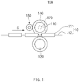
- FIG. 1 is a front view illustrating an apparatus for manufacturing an electrode assembly according to an embodiment of the present invention
- FIG. 2 is a plan view illustrating the apparatus for manufacturing the electrode assembly according to an embodiment of the present invention.
- an apparatus 100 for manufacturing an electrode assembly comprises a first roller 110 and a second roller 120 that press a stack 10 of electrodes 11 and a separator 12, which are alternately stacked, to combine the electrodes 11 and the separator 12 with each other, a first elastic part 140 provided along an outer circumferential surface of the first roller 110, and a first deformation prevention roller 150 that prevents the outer circumferential surface of the first elastic part 140 from being deformed.
- the apparatus 100 for manufacturing the electrode assembly according to an embodiment of the present invention may further comprise a first heater (not shown) that heats the first roller 110.
- the apparatus 100 for manufacturing the electrode assembly is an apparatus for manufacturing an electrode assembly by pressing the stack 10 of the electrodes and the separator 12 and combining the electrodes and the separator 12 with each other.
- the electrode assembly may be a power generation element that is chargeable and dischargeable and be accommodated in a battery case to manufacture a secondary battery.
- the electrode 11 may comprise a positive electrode and a negative electrode. Also, each of the separator separates a positive electrode and a negative electrode from each other to electrically insulate the positive electrode and the negative electrode from each other.
- the positive electrode may comprise a positive electrode collector and a positive electrode active material applied to the positive electrode collector.
- the positive electrode collector may be provided as foil made of an aluminum material, and the positive electrode active material may be made of lithium manganese oxide, lithium cobalt oxide, lithium nickel oxide, lithium iron phosphate, or a compound or mixture thereof containing at least one or more of the above-described materials.
- the negative electrode may comprise a negative electrode collector and a negative electrode active material applied to the negative electrode collector.
- the negative electrode collector may be provided as foil made of a copper (Cu) or nickel (Ni) material.
- the negative electrode active material may comprise synthetic graphite, lithium a metal, a lithium alloy, carbon, petroleum coke, activated carbon, graphite, a silicon compound, a tin compound, a titanium compound, or an alloy thereof.
- the negative electrode active material may further comprise, for example, non-graphite-based SiO (silica) or SiC (silicon carbide).
- the separator may be made of an insulation material, and the positive electrode, the separator, and the negative electrode may be alternately stacked.
- the separator 12 may be, for example, a multi-layered film produced by microporous polyethylene, polypropylene, or a combination thereof or a polymer film for solid polymer electrolytes or gel-type polymer electrolytes such as polyvinylidene fluoride, polyethylene oxide, polyacrylonitrile, or polyvinylidene fluoride hexafluoropropylene copolymers.
- the first roller 110 and the second roller 120 may press both sides of the stack 10 of the electrodes 11 and the separator 12, which are alternately stacked, to combine the electrodes 11 and the separator 12 with each other.
- each of the first roller 110 and the second roller 120 may be made of steel.
- the first roller 110 and the second roller 120 may be formed in, for example, a cylindrical shape to rotate about a central axis thereof.
- the central axes of the first roller 110 and the second roller 120 may be parallel to each other.
- the first roller 110 and the second roller 120 may rotate to continuously press the stack 10 that proceeds in a traveling direction G.
- first roller 110 may be disposed above the stack 10
- second roller 120 may be disposed below the stack 10 to press top and bottom surfaces of the stack 10.
- the first elastic part 140 may be provided along the outer circumferential surface of the first roller 110 and may comprise an elastic material.
- the first elastic part 140 made of the elastic material may be provided on the outer circumferential surface of the first roller 110 to prevent the stack 10 from being impacted and damaged.
- a phenomenon in which an impact is applied to the electrodes 11 and the separator 12 at the stepped portion of the stack 10 to destroy the electrodes 11 or the separator, resulting in a short detect may be prevented from occurring.
- a side portion of an electrode tab 11a, on which the stepped portion is formed may not be pressed.
- the side portion of the electrode tab 11a may be pressed by the first elastic part 140 made of the elastic material to improve sealing quality.
- the first elastic part 140 may be formed in a cylindrical shape.
- the first elastic part 140 may be made of, for example, a rubber material.
- the first deformation prevention roller 150 may be provided to be in contact with the outer circumferential surface of the first elastic part 140 so as to prevent the outer circumferential surface of the first elastic part 140 from being deformed.
- the first deformation prevention roller 150 may press the outer circumferential surface of the first elastic part 140 so that the stepped portion is not formed on the outer circumferential surface of the first elastic part 140.
- the first deformation prevention roller 150 may press the outer circumferential surface of the first elastic part 140 to spread a portion at which the stepped portion occurs to form a pressing surface on which the outer circumferential surface of the elastic part 140 is more uniform.
- the first deformation prevention roller 150 may be made of, for example, a steel material.
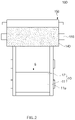
- FIG. 3 is a perspective see-through view illustrating an example of a first heater which is mounted on a first roller of an apparatus for manufacturing an electrode assembly according to another embodiment of the present invention.
- a first heater 170 may be provided on a first roller 110 to heat the first roller 110, thereby heating a stack 10 through the heated first roller 110.
- the first heater 170 may comprise, for example, a heating wire 171 provided inside the first roller 110. At this time, when electricity flows through the heating wire 171, the first roller 110 may be heated by resistance heat. Also, the first heater 170 may further comprise a heater rod 172 in which the heating wire 171 is accommodated therein. Here, the heating wire 171 may be wound in the heater rod 172 and mounted inside the first roller 110.
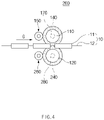
- FIG. 4 is a front view illustrating the apparatus for manufacturing the electrode assembly according to another embodiment of the present invention
- FIG. 5 is a bottom view illustrating the apparatus for manufacturing the electrode assembly according to another embodiment of the present invention.
- an apparatus 200 for manufacturing an electrode assembly comprises a first roller 110 and a second roller 120 that press a stack 10 of electrodes 11 and a separator 12, which are alternately stacked, to combine the electrodes 11 and the separator 12 with each other, a first elastic part 140 provided along an outer circumferential surface of the first roller 110, a first deformation prevention part 150 that prevents the outer circumferential surface of the first elastic part 140 from being deformed, a second elastic part 240 provided along an outer circumferential surface of the second roller 120, and a second deformation prevention roller 260 that prevents the outer circumferential surface of the second elastic part 240 from being deformed.
- the apparatus 200 for manufacturing the electrode assembly according to another embodiment of the present invention may further comprise a first heater that heats the first roller 110 and a second heater (not shown) that heats the second roller 120.
- the apparatus 200 for manufacturing the electrode assembly according to another embodiment of the present invention is different from the apparatus for manufacturing the electrode assembly according to the foregoing embodiment of the present invention in that the second elastic part 240 and the second deformation prevention roller 260 are further provided.
- contents duplicated with those of the apparatus for manufacturing the electrode assembly according to the foregoing embodiment and the apparatus for manufacturing the electrode assembly according to another embodiment will be omitted or briefly described, and also, only differences therebetween will be described.
- first roller 110 and the second roller 120 may press both sides of the stack 10 of the electrodes 11 and the separator 12, which are alternately stacked, to combine the electrodes 11 and the separator 12 with each other.
- each of the first roller 110 and the second roller 120 may be made of steel.
- the first roller 110 may be disposed above the stack 10, and the second roller 120 may be disposed below the stack 10 to press top and bottom surfaces of the stack 10.
- the first elastic part 140 may be provided along the outer circumferential surface of the first roller 110 and may comprise an elastic material.
- the first elastic part 140 may be formed in a cylindrical shape.
- the first elastic part 140 may be made of, for example, a rubber material.
- the second elastic part 240 may be provided along the outer circumferential surface of the second roller 120 and may comprise an elastic material.
- the second elastic part 240 may be formed in a cylindrical shape.
- the second elastic part 240 may be made of, for example, a rubber material.
- the first elastic part 140 and the second elastic part 240 are respectively provided on the outer circumferential surfaces of the first roller 110 and the second roller 120 to effectively prevent upper and lower portion of the stack 10 from being impacted and damaged.
- the first deformation prevention roller 150 may be provided to be in contact with the outer circumferential surface of the first elastic part 140 so as to prevent the outer circumferential surface of the first elastic part 140 from being deformed. Also, the first deformation prevention roller 150 may press the outer circumferential surface of the first elastic part 140 so that the stepped portion is not formed on the outer circumferential surface of the first elastic part 140.
- the first deformation prevention roller 150 may be made of, for example, a steel material.
- the second deformation prevention roller 260 may be provided to be in contact with the outer circumferential surface of the second elastic part 240 so as to prevent the outer circumferential surface of the second elastic part 240 from being deformed. Also, the second deformation prevention roller 260 may press the outer circumferential surface of the second elastic part 240 so that the stepped portion is not formed on the outer circumferential surface of the second elastic part 240.
- the second deformation prevention roller 260 may be made of, for example, a steel material.
- the first deformation prevention roller 150 and the second deformation prevention roller 260 may press the outer circumferential surface of the first elastic part 140 and the second elastic part 240 to spread a portion at which the stepped portion occurs to form a pressing surface on which each of the outer circumferential surfaces of the elastic part 140 and the second elastic part 240 is more uniform.
- the upper and lower portions of the stack 10 may be pressed to the first elastic part 140 and the second elastic part 240, on which the even pressing surfaces are formed, respectively, through the first roller 110 and the second roller 120 to seal the electrodes 11 and the separator 12 so as to combine the electrodes 11 and the separator 12 with each other, thereby significantly improving the sealing quality.
- FIG. 6 is a perspective see-through view illustrating an example of first and second heaters which are respectively mounted on first and second rollers of the apparatus for manufacturing the electrode assembly according to another embodiment of the present invention
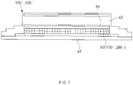
- FIG. 7 is a cross-sectional view illustrating another example of a main part of the first and second heaters, which are respectively mounted on rollers of the apparatus for manufacturing the electrode assembly according to another embodiment of the present invention.
- a first heater 170 may be provided on the first roller 110 to heat the first roller 110. Thus, heat may be applied to the stack 10 through the heated first roller 110.
- a second heater 280 may be provided on the second roller 120 to heat the second roller 120. Thus, heat may be applied to the stack 10 through the heated second roller 120.
- the first heater 170 and the second heater 280 may comprise, for example, heating wires 171 and 181 provided inside the first roller 110 and the second roller 120, respectively. At this time, when electricity flows through the heating wires 171 and 181, the first roller 110 and the second roller 120 may be heated by resistance heat. Also, the first heater 170 and the second heater 280 may further comprise heater rods 172 and 282 in which the heating wires 171 and 281 are accommodated therein, respectively. Here, the heating wires 171 and 281 may be wound in the heater rods 172 and 282 and mounted inside the first roller 110 and the second roller 120, respectively.
- each of a first heater 170' and a second heater 280' may be provided as an induction heating heater as another example.
- each of the first roll 110' and the second roller 120' may comprise a shaft A1 provided at a center thereof, an induction coil A2 wound around an outer circumferential surface of the shaft A1, and an outer cylinder A3 provided on an outer circumferential surface thereof.
- the induction coil A3 when power is supplied to the induction coil A3, a magnetic flux crossing the outer cylinder A3 of the first roller 110' and the second roller 120' is generated, and the magnetic flux generates an eddy current in the outer cylinder A3 to generate a current flow such as an equivalent circuit, thereby heating the outer cylinder A3.
- heating of an initial heating portion A4 in the outer cylinder A3 starts to heat the entire outer cylinder A3. Therefore, the first roller 110' and the second roller 120' are heated in the induction heating manner, and thus, the inside and outside of the whole rollers may be heated simultaneously to maintain a temperature deviation within a temperature of 1°C. Also, a heating time (about 15 minutes) is fast, and there is no over-heating when stopped.
Landscapes
- Chemical & Material Sciences (AREA)
- Chemical Kinetics & Catalysis (AREA)
- Electrochemistry (AREA)
- General Chemical & Material Sciences (AREA)
- Engineering & Computer Science (AREA)
- Manufacturing & Machinery (AREA)
- Secondary Cells (AREA)
- Battery Electrode And Active Subsutance (AREA)
Applications Claiming Priority (2)
| Application Number | Priority Date | Filing Date | Title |
|---|---|---|---|
| KR1020190166055A KR102675004B1 (ko) | 2019-12-12 | 2019-12-12 | 전극 조립체 제조장치와, 이를 통해 제조된 전극 조립체 및 이차전지 |
| PCT/KR2020/017823 WO2021118197A1 (ko) | 2019-12-12 | 2020-12-08 | 전극 조립체 제조장치와, 이를 통해 제조된 전극 조립체 및 이차전지 |
Publications (2)
| Publication Number | Publication Date |
|---|---|
| EP4057403A1 true EP4057403A1 (de) | 2022-09-14 |
| EP4057403A4 EP4057403A4 (de) | 2024-02-07 |
Family
ID=76330163
Family Applications (1)
| Application Number | Title | Priority Date | Filing Date |
|---|---|---|---|
| EP20898163.9A Pending EP4057403A4 (de) | 2019-12-12 | 2020-12-08 | Vorrichtung zur herstellung einer elektrodenanordnung, damit hergestellte elektrodenanordnung und sekundärbatterie |
Country Status (5)
| Country | Link |
|---|---|
| US (1) | US20230105865A1 (de) |
| EP (1) | EP4057403A4 (de) |
| KR (1) | KR102675004B1 (de) |
| CN (1) | CN114762159A (de) |
| WO (1) | WO2021118197A1 (de) |
Cited By (1)
| Publication number | Priority date | Publication date | Assignee | Title |
|---|---|---|---|---|
| DE102022128222A1 (de) | 2022-10-25 | 2024-04-25 | Körber Technologies Gmbh | Laminiervorrichtung zum Laminieren von mehrlagigen Endlosbahnen zur Herstellung von Energiezellen |
Families Citing this family (1)
| Publication number | Priority date | Publication date | Assignee | Title |
|---|---|---|---|---|
| CN115838091A (zh) * | 2021-09-18 | 2023-03-24 | 宁德时代新能源科技股份有限公司 | 辊组件 |
Family Cites Families (13)
| Publication number | Priority date | Publication date | Assignee | Title |
|---|---|---|---|---|
| JPH1050300A (ja) * | 1996-07-30 | 1998-02-20 | Yamauchi Corp | 薄層電極製造用プレスロール、該ロールを用いた薄層電極製造用プレス装置および同薄層電極の製造方法 |
| JPH10228897A (ja) * | 1997-02-13 | 1998-08-25 | Matsushita Electric Ind Co Ltd | 電池電極の製造方法および製造装置 |
| JPH11176473A (ja) * | 1997-12-10 | 1999-07-02 | Toshiba Battery Co Ltd | ポリマー電池用電極要素の製造装置 |
| AU7318500A (en) * | 1999-09-22 | 2001-04-24 | Itochu Corporation | Electrode structure, and rolling machine for working electrode structure |
| JP3793869B2 (ja) * | 2000-06-12 | 2006-07-05 | グンゼ株式会社 | 表面平滑性フッ素系樹脂チューブ及び加圧ローラ |
| WO2004026498A1 (en) * | 2002-09-18 | 2004-04-01 | Avestor Limited Partnership | Lamination process and apparatus for alkali metals or alloys thereof |
| CN102569732B (zh) * | 2012-03-16 | 2014-07-02 | 天津力神电池股份有限公司 | 一种电池极片碾压辊极差的自动修复方法 |
| KR101528001B1 (ko) | 2012-06-22 | 2015-06-10 | 주식회사 엘지화학 | 이차전지용 전극조립체, 그 제조방법 및 이를 이용한 이차전지 |
| KR101532730B1 (ko) * | 2013-01-16 | 2015-06-30 | 주식회사 엘지화학 | 전극조립체의 제조장치 |
| JP6127998B2 (ja) * | 2014-01-31 | 2017-05-17 | 株式会社豊田自動織機 | プレス装置 |
| CN105082524B (zh) * | 2015-08-10 | 2017-07-18 | 苏州市创怡盛实业有限公司 | 辊表面处理方法及表面改性的辊 |
| JP6870233B2 (ja) * | 2016-07-29 | 2021-05-12 | 株式会社豊田自動織機 | 電極製造装置 |
| CN107225069A (zh) * | 2017-06-09 | 2017-10-03 | 中山松德新材料装备有限公司 | 一种新型涂布机复合压辊机构 |
-
2019
- 2019-12-12 KR KR1020190166055A patent/KR102675004B1/ko active IP Right Grant
-
2020
- 2020-12-08 CN CN202080082304.0A patent/CN114762159A/zh active Pending
- 2020-12-08 EP EP20898163.9A patent/EP4057403A4/de active Pending
- 2020-12-08 WO PCT/KR2020/017823 patent/WO2021118197A1/ko unknown
- 2020-12-08 US US17/783,683 patent/US20230105865A1/en active Pending
Cited By (2)
| Publication number | Priority date | Publication date | Assignee | Title |
|---|---|---|---|---|
| DE102022128222A1 (de) | 2022-10-25 | 2024-04-25 | Körber Technologies Gmbh | Laminiervorrichtung zum Laminieren von mehrlagigen Endlosbahnen zur Herstellung von Energiezellen |
| WO2024088826A1 (de) * | 2022-10-25 | 2024-05-02 | Körber Technologies Gmbh | Laminiervorrichtung zum laminieren von mehrlagigen endlosbahnen zur herstellung von energiezellen |
Also Published As
| Publication number | Publication date |
|---|---|
| KR20210074907A (ko) | 2021-06-22 |
| US20230105865A1 (en) | 2023-04-06 |
| WO2021118197A1 (ko) | 2021-06-17 |
| EP4057403A4 (de) | 2024-02-07 |
| KR102675004B1 (ko) | 2024-06-14 |
| CN114762159A (zh) | 2022-07-15 |
Similar Documents
| Publication | Publication Date | Title |
|---|---|---|
| EP3537497B1 (de) | Sekundärbatterie, herstellungsverfahren dafür und pressblock zur herstellung einer sekundärbatterie | |
| KR102480958B1 (ko) | 이차전지 | |
| EP3905417A1 (de) | Verfahren zur herstellung einer elektrodenanordnung und damit hergestellte elektrode und sekundärbatterie | |
| CN209312928U (zh) | 电极组件 | |
| US20240055741A1 (en) | Electrode assembly and secondary battery comprising the same | |
| JP7372006B2 (ja) | 二次電池およびそれを含むデバイス | |
| CN110226242B (zh) | 二次电池和制造二次电池的方法及压块 | |
| US20240313266A1 (en) | Secondary Battery | |
| EP4057403A1 (de) | Vorrichtung zur herstellung einer elektrodenanordnung, damit hergestellte elektrodenanordnung und sekundärbatterie | |
| CN110168792B (zh) | 用于制造电极组件的装置和方法 | |
| KR20230046461A (ko) | 전극 조립체 제조방법 및 제조장치 | |
| US20220376321A1 (en) | Electrode assembly and secondary battery comprising the same | |
| WO2023100815A1 (ja) | 蓄電装置および蓄電装置の製造方法 | |
| US20240088520A1 (en) | Method for manufacturing electrode assembly and electrode assembly manufactured therethrough | |
| US11742541B2 (en) | Secondary battery | |
| KR102141123B1 (ko) | 전극 조립체 | |
| US20230198042A1 (en) | Electrode assembly and secondary battery comprising the same | |
| JP6108119B2 (ja) | 密閉型二次電池 | |
| US20220294082A1 (en) | Electrode Assembly and Method for Manufacturing the Same | |
| KR20210012457A (ko) | 이차전지 제조방법 및 이차전지 | |
| KR20190075381A (ko) | 전극 조립체 및 이를 포함하는 이차전지 |
Legal Events
| Date | Code | Title | Description |
|---|---|---|---|
| STAA | Information on the status of an ep patent application or granted ep patent |
Free format text: STATUS: THE INTERNATIONAL PUBLICATION HAS BEEN MADE |
|
| PUAI | Public reference made under article 153(3) epc to a published international application that has entered the european phase |
Free format text: ORIGINAL CODE: 0009012 |
|
| STAA | Information on the status of an ep patent application or granted ep patent |
Free format text: STATUS: REQUEST FOR EXAMINATION WAS MADE |
|
| 17P | Request for examination filed |
Effective date: 20220609 |
|
| AK | Designated contracting states |
Kind code of ref document: A1 Designated state(s): AL AT BE BG CH CY CZ DE DK EE ES FI FR GB GR HR HU IE IS IT LI LT LU LV MC MK MT NL NO PL PT RO RS SE SI SK SM TR |
|
| DAV | Request for validation of the european patent (deleted) | ||
| DAX | Request for extension of the european patent (deleted) | ||
| A4 | Supplementary search report drawn up and despatched |
Effective date: 20240109 |
|
| RIC1 | Information provided on ipc code assigned before grant |
Ipc: H01M 4/04 20060101ALI20240103BHEP Ipc: H01M 10/0585 20100101ALI20240103BHEP Ipc: H01M 10/04 20060101AFI20240103BHEP |