EP4056313B1 - Drehpositioniervorrichtung - Google Patents
Drehpositioniervorrichtung Download PDFInfo
- Publication number
- EP4056313B1 EP4056313B1 EP20883796.3A EP20883796A EP4056313B1 EP 4056313 B1 EP4056313 B1 EP 4056313B1 EP 20883796 A EP20883796 A EP 20883796A EP 4056313 B1 EP4056313 B1 EP 4056313B1
- Authority
- EP
- European Patent Office
- Prior art keywords
- rotational
- rotational member
- sensor
- positioning device
- housing
- Prior art date
- Legal status (The legal status is an assumption and is not a legal conclusion. Google has not performed a legal analysis and makes no representation as to the accuracy of the status listed.)
- Active
Links
Images


Classifications
-
- G—PHYSICS
- G01—MEASURING; TESTING
- G01D—MEASURING NOT SPECIALLY ADAPTED FOR A SPECIFIC VARIABLE; ARRANGEMENTS FOR MEASURING TWO OR MORE VARIABLES NOT COVERED IN A SINGLE OTHER SUBCLASS; TARIFF METERING APPARATUS; MEASURING OR TESTING NOT OTHERWISE PROVIDED FOR
- G01D18/00—Testing or calibrating apparatus or arrangements provided for in groups G01D1/00 - G01D15/00
- G01D18/001—Calibrating encoders
-
- B—PERFORMING OPERATIONS; TRANSPORTING
- B23—MACHINE TOOLS; METAL-WORKING NOT OTHERWISE PROVIDED FOR
- B23Q—DETAILS, COMPONENTS, OR ACCESSORIES FOR MACHINE TOOLS, e.g. ARRANGEMENTS FOR COPYING OR CONTROLLING; MACHINE TOOLS IN GENERAL CHARACTERISED BY THE CONSTRUCTION OF PARTICULAR DETAILS OR COMPONENTS; COMBINATIONS OR ASSOCIATIONS OF METAL-WORKING MACHINES, NOT DIRECTED TO A PARTICULAR RESULT
- B23Q17/00—Arrangements for observing, indicating or measuring on machine tools
-
- B—PERFORMING OPERATIONS; TRANSPORTING
- B23—MACHINE TOOLS; METAL-WORKING NOT OTHERWISE PROVIDED FOR
- B23Q—DETAILS, COMPONENTS, OR ACCESSORIES FOR MACHINE TOOLS, e.g. ARRANGEMENTS FOR COPYING OR CONTROLLING; MACHINE TOOLS IN GENERAL CHARACTERISED BY THE CONSTRUCTION OF PARTICULAR DETAILS OR COMPONENTS; COMBINATIONS OR ASSOCIATIONS OF METAL-WORKING MACHINES, NOT DIRECTED TO A PARTICULAR RESULT
- B23Q1/00—Members which are comprised in the general build-up of a form of machine, particularly relatively large fixed members
- B23Q1/25—Movable or adjustable work or tool supports
- B23Q1/44—Movable or adjustable work or tool supports using particular mechanisms
- B23Q1/50—Movable or adjustable work or tool supports using particular mechanisms with rotating pairs only, the rotating pairs being the first two elements of the mechanism
- B23Q1/52—Movable or adjustable work or tool supports using particular mechanisms with rotating pairs only, the rotating pairs being the first two elements of the mechanism a single rotating pair
-
- B—PERFORMING OPERATIONS; TRANSPORTING
- B23—MACHINE TOOLS; METAL-WORKING NOT OTHERWISE PROVIDED FOR
- B23Q—DETAILS, COMPONENTS, OR ACCESSORIES FOR MACHINE TOOLS, e.g. ARRANGEMENTS FOR COPYING OR CONTROLLING; MACHINE TOOLS IN GENERAL CHARACTERISED BY THE CONSTRUCTION OF PARTICULAR DETAILS OR COMPONENTS; COMBINATIONS OR ASSOCIATIONS OF METAL-WORKING MACHINES, NOT DIRECTED TO A PARTICULAR RESULT
- B23Q17/00—Arrangements for observing, indicating or measuring on machine tools
- B23Q17/002—Arrangements for observing, indicating or measuring on machine tools for indicating or measuring the holding action of work or tool holders
- B23Q17/003—Arrangements for observing, indicating or measuring on machine tools for indicating or measuring the holding action of work or tool holders by measuring a position
-
- F—MECHANICAL ENGINEERING; LIGHTING; HEATING; WEAPONS; BLASTING
- F16—ENGINEERING ELEMENTS AND UNITS; GENERAL MEASURES FOR PRODUCING AND MAINTAINING EFFECTIVE FUNCTIONING OF MACHINES OR INSTALLATIONS; THERMAL INSULATION IN GENERAL
- F16C—SHAFTS; FLEXIBLE SHAFTS; ELEMENTS OR CRANKSHAFT MECHANISMS; ROTARY BODIES OTHER THAN GEARING ELEMENTS; BEARINGS
- F16C19/00—Bearings with rolling contact, for exclusively rotary movement
- F16C19/02—Bearings with rolling contact, for exclusively rotary movement with bearing balls essentially of the same size in one or more circular rows
- F16C19/14—Bearings with rolling contact, for exclusively rotary movement with bearing balls essentially of the same size in one or more circular rows for both radial and axial load
-
- F—MECHANICAL ENGINEERING; LIGHTING; HEATING; WEAPONS; BLASTING
- F16—ENGINEERING ELEMENTS AND UNITS; GENERAL MEASURES FOR PRODUCING AND MAINTAINING EFFECTIVE FUNCTIONING OF MACHINES OR INSTALLATIONS; THERMAL INSULATION IN GENERAL
- F16C—SHAFTS; FLEXIBLE SHAFTS; ELEMENTS OR CRANKSHAFT MECHANISMS; ROTARY BODIES OTHER THAN GEARING ELEMENTS; BEARINGS
- F16C19/00—Bearings with rolling contact, for exclusively rotary movement
- F16C19/22—Bearings with rolling contact, for exclusively rotary movement with bearing rollers essentially of the same size in one or more circular rows, e.g. needle bearings
- F16C19/24—Bearings with rolling contact, for exclusively rotary movement with bearing rollers essentially of the same size in one or more circular rows, e.g. needle bearings for radial load mainly
- F16C19/26—Bearings with rolling contact, for exclusively rotary movement with bearing rollers essentially of the same size in one or more circular rows, e.g. needle bearings for radial load mainly with a single row of rollers
-
- F—MECHANICAL ENGINEERING; LIGHTING; HEATING; WEAPONS; BLASTING
- F16—ENGINEERING ELEMENTS AND UNITS; GENERAL MEASURES FOR PRODUCING AND MAINTAINING EFFECTIVE FUNCTIONING OF MACHINES OR INSTALLATIONS; THERMAL INSULATION IN GENERAL
- F16C—SHAFTS; FLEXIBLE SHAFTS; ELEMENTS OR CRANKSHAFT MECHANISMS; ROTARY BODIES OTHER THAN GEARING ELEMENTS; BEARINGS
- F16C19/00—Bearings with rolling contact, for exclusively rotary movement
- F16C19/22—Bearings with rolling contact, for exclusively rotary movement with bearing rollers essentially of the same size in one or more circular rows, e.g. needle bearings
- F16C19/30—Bearings with rolling contact, for exclusively rotary movement with bearing rollers essentially of the same size in one or more circular rows, e.g. needle bearings for axial load mainly
-
- F—MECHANICAL ENGINEERING; LIGHTING; HEATING; WEAPONS; BLASTING
- F16—ENGINEERING ELEMENTS AND UNITS; GENERAL MEASURES FOR PRODUCING AND MAINTAINING EFFECTIVE FUNCTIONING OF MACHINES OR INSTALLATIONS; THERMAL INSULATION IN GENERAL
- F16C—SHAFTS; FLEXIBLE SHAFTS; ELEMENTS OR CRANKSHAFT MECHANISMS; ROTARY BODIES OTHER THAN GEARING ELEMENTS; BEARINGS
- F16C19/00—Bearings with rolling contact, for exclusively rotary movement
- F16C19/54—Systems consisting of a plurality of bearings with rolling friction
- F16C19/541—Systems consisting of juxtaposed rolling bearings including at least one angular contact bearing
-
- F—MECHANICAL ENGINEERING; LIGHTING; HEATING; WEAPONS; BLASTING
- F16—ENGINEERING ELEMENTS AND UNITS; GENERAL MEASURES FOR PRODUCING AND MAINTAINING EFFECTIVE FUNCTIONING OF MACHINES OR INSTALLATIONS; THERMAL INSULATION IN GENERAL
- F16C—SHAFTS; FLEXIBLE SHAFTS; ELEMENTS OR CRANKSHAFT MECHANISMS; ROTARY BODIES OTHER THAN GEARING ELEMENTS; BEARINGS
- F16C33/00—Parts of bearings; Special methods for making bearings or parts thereof
- F16C33/02—Parts of sliding-contact bearings
-
- F—MECHANICAL ENGINEERING; LIGHTING; HEATING; WEAPONS; BLASTING
- F16—ENGINEERING ELEMENTS AND UNITS; GENERAL MEASURES FOR PRODUCING AND MAINTAINING EFFECTIVE FUNCTIONING OF MACHINES OR INSTALLATIONS; THERMAL INSULATION IN GENERAL
- F16C—SHAFTS; FLEXIBLE SHAFTS; ELEMENTS OR CRANKSHAFT MECHANISMS; ROTARY BODIES OTHER THAN GEARING ELEMENTS; BEARINGS
- F16C33/00—Parts of bearings; Special methods for making bearings or parts thereof
- F16C33/30—Parts of ball or roller bearings
- F16C33/58—Raceways; Race rings
- F16C33/581—Raceways; Race rings integral with other parts, e.g. with housings or machine elements such as shafts or gear wheels
-
- F—MECHANICAL ENGINEERING; LIGHTING; HEATING; WEAPONS; BLASTING
- F16—ENGINEERING ELEMENTS AND UNITS; GENERAL MEASURES FOR PRODUCING AND MAINTAINING EFFECTIVE FUNCTIONING OF MACHINES OR INSTALLATIONS; THERMAL INSULATION IN GENERAL
- F16C—SHAFTS; FLEXIBLE SHAFTS; ELEMENTS OR CRANKSHAFT MECHANISMS; ROTARY BODIES OTHER THAN GEARING ELEMENTS; BEARINGS
- F16C41/00—Other accessories, e.g. devices integrated in the bearing not relating to the bearing function as such
- F16C41/007—Encoders, e.g. parts with a plurality of alternating magnetic poles
-
- F—MECHANICAL ENGINEERING; LIGHTING; HEATING; WEAPONS; BLASTING
- F16—ENGINEERING ELEMENTS AND UNITS; GENERAL MEASURES FOR PRODUCING AND MAINTAINING EFFECTIVE FUNCTIONING OF MACHINES OR INSTALLATIONS; THERMAL INSULATION IN GENERAL
- F16H—GEARING
- F16H1/00—Toothed gearings for conveying rotary motion
- F16H1/02—Toothed gearings for conveying rotary motion without gears having orbital motion
- F16H1/04—Toothed gearings for conveying rotary motion without gears having orbital motion involving only two intermeshing members
- F16H1/12—Toothed gearings for conveying rotary motion without gears having orbital motion involving only two intermeshing members with non-parallel axes
- F16H1/16—Toothed gearings for conveying rotary motion without gears having orbital motion involving only two intermeshing members with non-parallel axes comprising worm and worm-wheel
-
- F—MECHANICAL ENGINEERING; LIGHTING; HEATING; WEAPONS; BLASTING
- F16—ENGINEERING ELEMENTS AND UNITS; GENERAL MEASURES FOR PRODUCING AND MAINTAINING EFFECTIVE FUNCTIONING OF MACHINES OR INSTALLATIONS; THERMAL INSULATION IN GENERAL
- F16M—FRAMES, CASINGS OR BEDS OF ENGINES, MACHINES OR APPARATUS, NOT SPECIFIC TO ENGINES, MACHINES OR APPARATUS PROVIDED FOR ELSEWHERE; STANDS; SUPPORTS
- F16M11/00—Stands or trestles as supports for apparatus or articles placed thereon ; Stands for scientific apparatus such as gravitational force meters
- F16M11/02—Heads
- F16M11/04—Means for attachment of apparatus; Means allowing adjustment of the apparatus relatively to the stand
- F16M11/06—Means for attachment of apparatus; Means allowing adjustment of the apparatus relatively to the stand allowing pivoting
- F16M11/08—Means for attachment of apparatus; Means allowing adjustment of the apparatus relatively to the stand allowing pivoting around a vertical axis, e.g. panoramic heads
-
- G—PHYSICS
- G01—MEASURING; TESTING
- G01D—MEASURING NOT SPECIALLY ADAPTED FOR A SPECIFIC VARIABLE; ARRANGEMENTS FOR MEASURING TWO OR MORE VARIABLES NOT COVERED IN A SINGLE OTHER SUBCLASS; TARIFF METERING APPARATUS; MEASURING OR TESTING NOT OTHERWISE PROVIDED FOR
- G01D5/00—Mechanical means for transferring the output of a sensing member; Means for converting the output of a sensing member to another variable where the form or nature of the sensing member does not constrain the means for converting; Transducers not specially adapted for a specific variable
- G01D5/12—Mechanical means for transferring the output of a sensing member; Means for converting the output of a sensing member to another variable where the form or nature of the sensing member does not constrain the means for converting; Transducers not specially adapted for a specific variable using electric or magnetic means
- G01D5/244—Mechanical means for transferring the output of a sensing member; Means for converting the output of a sensing member to another variable where the form or nature of the sensing member does not constrain the means for converting; Transducers not specially adapted for a specific variable using electric or magnetic means influencing characteristics of pulses or pulse trains; generating pulses or pulse trains
- G01D5/24428—Error prevention
- G01D5/24433—Error prevention by mechanical means
- G01D5/24442—Error prevention by mechanical means by mounting means
-
- G—PHYSICS
- G01—MEASURING; TESTING
- G01D—MEASURING NOT SPECIALLY ADAPTED FOR A SPECIFIC VARIABLE; ARRANGEMENTS FOR MEASURING TWO OR MORE VARIABLES NOT COVERED IN A SINGLE OTHER SUBCLASS; TARIFF METERING APPARATUS; MEASURING OR TESTING NOT OTHERWISE PROVIDED FOR
- G01D5/00—Mechanical means for transferring the output of a sensing member; Means for converting the output of a sensing member to another variable where the form or nature of the sensing member does not constrain the means for converting; Transducers not specially adapted for a specific variable
- G01D5/12—Mechanical means for transferring the output of a sensing member; Means for converting the output of a sensing member to another variable where the form or nature of the sensing member does not constrain the means for converting; Transducers not specially adapted for a specific variable using electric or magnetic means
- G01D5/244—Mechanical means for transferring the output of a sensing member; Means for converting the output of a sensing member to another variable where the form or nature of the sensing member does not constrain the means for converting; Transducers not specially adapted for a specific variable using electric or magnetic means influencing characteristics of pulses or pulse trains; generating pulses or pulse trains
- G01D5/245—Mechanical means for transferring the output of a sensing member; Means for converting the output of a sensing member to another variable where the form or nature of the sensing member does not constrain the means for converting; Transducers not specially adapted for a specific variable using electric or magnetic means influencing characteristics of pulses or pulse trains; generating pulses or pulse trains using a variable number of pulses in a train
- G01D5/2451—Incremental encoders
-
- G—PHYSICS
- G01—MEASURING; TESTING
- G01D—MEASURING NOT SPECIALLY ADAPTED FOR A SPECIFIC VARIABLE; ARRANGEMENTS FOR MEASURING TWO OR MORE VARIABLES NOT COVERED IN A SINGLE OTHER SUBCLASS; TARIFF METERING APPARATUS; MEASURING OR TESTING NOT OTHERWISE PROVIDED FOR
- G01D5/00—Mechanical means for transferring the output of a sensing member; Means for converting the output of a sensing member to another variable where the form or nature of the sensing member does not constrain the means for converting; Transducers not specially adapted for a specific variable
- G01D5/26—Mechanical means for transferring the output of a sensing member; Means for converting the output of a sensing member to another variable where the form or nature of the sensing member does not constrain the means for converting; Transducers not specially adapted for a specific variable characterised by optical transfer means, i.e. using infrared, visible, or ultraviolet light
- G01D5/32—Mechanical means for transferring the output of a sensing member; Means for converting the output of a sensing member to another variable where the form or nature of the sensing member does not constrain the means for converting; Transducers not specially adapted for a specific variable characterised by optical transfer means, i.e. using infrared, visible, or ultraviolet light with attenuation or whole or partial obturation of beams of light
- G01D5/34—Mechanical means for transferring the output of a sensing member; Means for converting the output of a sensing member to another variable where the form or nature of the sensing member does not constrain the means for converting; Transducers not specially adapted for a specific variable characterised by optical transfer means, i.e. using infrared, visible, or ultraviolet light with attenuation or whole or partial obturation of beams of light the beams of light being detected by photocells
- G01D5/347—Mechanical means for transferring the output of a sensing member; Means for converting the output of a sensing member to another variable where the form or nature of the sensing member does not constrain the means for converting; Transducers not specially adapted for a specific variable characterised by optical transfer means, i.e. using infrared, visible, or ultraviolet light with attenuation or whole or partial obturation of beams of light the beams of light being detected by photocells using displacement encoding scales
- G01D5/34707—Scales; Discs, e.g. fixation, fabrication, compensation
-
- B—PERFORMING OPERATIONS; TRANSPORTING
- B23—MACHINE TOOLS; METAL-WORKING NOT OTHERWISE PROVIDED FOR
- B23Q—DETAILS, COMPONENTS, OR ACCESSORIES FOR MACHINE TOOLS, e.g. ARRANGEMENTS FOR COPYING OR CONTROLLING; MACHINE TOOLS IN GENERAL CHARACTERISED BY THE CONSTRUCTION OF PARTICULAR DETAILS OR COMPONENTS; COMBINATIONS OR ASSOCIATIONS OF METAL-WORKING MACHINES, NOT DIRECTED TO A PARTICULAR RESULT
- B23Q16/00—Equipment for precise positioning of tool or work into particular locations not otherwise provided for
- B23Q16/02—Indexing equipment
- B23Q16/022—Indexing equipment in which only the indexing movement is of importance
- B23Q16/025—Indexing equipment in which only the indexing movement is of importance by converting a continuous movement into a rotary indexing movement
-
- B—PERFORMING OPERATIONS; TRANSPORTING
- B23—MACHINE TOOLS; METAL-WORKING NOT OTHERWISE PROVIDED FOR
- B23Q—DETAILS, COMPONENTS, OR ACCESSORIES FOR MACHINE TOOLS, e.g. ARRANGEMENTS FOR COPYING OR CONTROLLING; MACHINE TOOLS IN GENERAL CHARACTERISED BY THE CONSTRUCTION OF PARTICULAR DETAILS OR COMPONENTS; COMBINATIONS OR ASSOCIATIONS OF METAL-WORKING MACHINES, NOT DIRECTED TO A PARTICULAR RESULT
- B23Q17/00—Arrangements for observing, indicating or measuring on machine tools
- B23Q17/22—Arrangements for observing, indicating or measuring on machine tools for indicating or measuring existing or desired position of tool or work
-
- B—PERFORMING OPERATIONS; TRANSPORTING
- B23—MACHINE TOOLS; METAL-WORKING NOT OTHERWISE PROVIDED FOR
- B23Q—DETAILS, COMPONENTS, OR ACCESSORIES FOR MACHINE TOOLS, e.g. ARRANGEMENTS FOR COPYING OR CONTROLLING; MACHINE TOOLS IN GENERAL CHARACTERISED BY THE CONSTRUCTION OF PARTICULAR DETAILS OR COMPONENTS; COMBINATIONS OR ASSOCIATIONS OF METAL-WORKING MACHINES, NOT DIRECTED TO A PARTICULAR RESULT
- B23Q2220/00—Machine tool components
- B23Q2220/004—Rotary tables
-
- F—MECHANICAL ENGINEERING; LIGHTING; HEATING; WEAPONS; BLASTING
- F16—ENGINEERING ELEMENTS AND UNITS; GENERAL MEASURES FOR PRODUCING AND MAINTAINING EFFECTIVE FUNCTIONING OF MACHINES OR INSTALLATIONS; THERMAL INSULATION IN GENERAL
- F16C—SHAFTS; FLEXIBLE SHAFTS; ELEMENTS OR CRANKSHAFT MECHANISMS; ROTARY BODIES OTHER THAN GEARING ELEMENTS; BEARINGS
- F16C2322/00—Apparatus used in shaping articles
- F16C2322/39—General buildup of machine tools, e.g. spindles, slides, actuators
Definitions
- the present invention relates to a rotational positioning device capable of positioning a rotational angle at a target angle position with high precision.
- the rotational positioning device generally has an input shaft into which a driving force such as a motor is input and an output shaft on which a rotational table for loading a machining work and the like of a machine tool is mounted.
- An angle detector such as an encoder is installed to the input shaft or output shaft, and the angle detector detects an angle change amount due to rotation of the rotational table.
- the rotational positioning device controls a driver and a motor based on the detected angle change amount to rotate and position the rotational table at a target angle position.
- Patent Literature 1 discloses a roller turret cam index device.
- the roller turret cam index device includes a roller gear and a roller gear cam that are meshed with each other.
- the roller gear and the roller gear cam are rotatably provided around two rotation axial lines that three-dimensionally cross.
- an encoder which is a rotation angle detector, is fixed to the housing by an adapter.
- the input shaft of the encoder is connected to the roller gear shaft of the roller gear by a coupling so as not to be relatively rotatable to the roller gear shaft.
- the encoder detects the rotation of the roller gear shaft.
- the value detected by the encoder represents the rotation stop position of the roller gear, that is, the index position.
- Patent Literature 2 discloses a rotational table device.
- the rotational table device includes: a circular table on which a work is loaded; a rotational shaft for supporting the rotary table; a frame for rotatably supporting the rotational shaft; and a motor accommodated between the frame and the rotational shaft.
- the circular table together with the rotational shaft, rotates about the rotational shaft axial line, with respect to the frame, and the angle position of the circular table is determined.
- the rotational shaft is composed of two shaft members. Both the shaft members are combined in a state in which their axial lines are aligned, and are connected by a screw member.
- the rotation detector includes an encoder for detecting a rotation amount of the rotational shaft and an object to be detected by the encoder.
- the encoder provided on the frame detects the object to be detected separately provided on one of the shaft members of the rotational shaft. Thus, based on the detection signal from the encoder, the rotation amount of the rotational shaft is detected.
- Patent Literature 6 discloses a machine tool including a processing head which can be positioned along three translation axes which are directed so as to be diagonal to one another, a slewing gear which can slew around a horizontal pivot, a work-piece positioning device which is rotatable around a rotation axis directed perpendicularly to the horizontal pivot, and a measurement frame, which is additionally provided on the slewing gear, can slew together with the slewing gear, and has constituents of a first position measuring system measuring a spatial position of the processing head and constituents of a second position measuring system measuring a spatial position of the work-piece positioning device.
- Patent Literature 7 discloses a code wheel for a rotary encoder including, in a central portion, a hole into which a rotary shaft of a rotary member is fitted and a code portion including a radial code pattern in a circumferential edge portion.
- Patent Literature 8 discloses a measuring arrangement calibrated for determining rotational positions of a rotary device that has a first part and a second part which can be rotated relative to the first part about a rotational axis.
- Patent Literature 9 discloses an electron-beam recording device including a scale having graduations formed to indicate the rotational angular position of a turntable, and at least three read heads arranged at predetermined relative angles on a circumference on the center of rotation of the turntable, for individually reading the graduations to generate read signals.
- Patent Literature 10 discloses an encoder system including a signal processing circuit including a first position data detection circuit that detects first position data representing positional displacement in rotation of an input shaft, a second position data detection circuit that detects second position data representing positional displacement in rotation of an output shaft, a position data combination circuit that combines the first and second position data to generate combined position data representing the number of rotations of the input shaft and the positional displacement within one rotation of the input shaft, and a position data comparing and collating circuit that compares and collates the first and second position data.
- Patent Literature 11 discloses a wheel bearing device with a rotation detector for use in an automotive vehicle of a type equipped with an anti-lock brake system.
- the roller turret cam index device of Patent Literature 1 has the encoder externally installed. This increases the size of the roller turret cam index device by the volume of the encoder and further leads to higher cost.
- the device of Patent Literature 1 has such problems.
- the encoder externally installed generates an offset between the rotation axial line of the encoder input shaft and the rotation axial line of the roller gear shaft, during assembly in connecting the encoder input shaft and the roller gear shaft.
- the offset is also called a center deviation.
- the influence of the assembly error caused by this center deviation generates an error in angle change amount, of the roller gear, detected by the encoder.
- the influence further generates an error in the target angle position of the roller gear.
- the device of Patent Literature 1 also has such problems.
- the roller gear is generally hollow, the encoder externally installed structurally blocks one of the hollow openings. This does not allow the roller gear to pass the cables, hydraulic parts, and the like through the hollow.
- the device of Patent Literature 1 also has such a problem
- a rotational table device of Patent Literature 2 has a rotational shaft composed of two shaft members. Both the shaft members are combined with their axial line aligned.
- a center deviation is generated during assembly in combining the two shaft members.
- a center deviation is generated during assembly in separately providing an object to be detected on one of the shaft members of the rotational shaft.
- the influence of the assembly errors caused by these center deviations generates an error in the angle change amount, of the rotational shaft, detected by the rotation detector.
- the influence further generates an error in the target angle position of the rotational shaft.
- the device of Patent Literature 2 has such problems. Further, the raceway surface of the bearing is separately provided on the rotational shaft.
- the assembly error during assembly in separately providing the raceway surface generates an error in the angle change amount, of the rotational shaft, detected by the rotation detector.
- the influence further generates an error in the target angle position of the rotational shaft.
- the device of Patent Literature 2 also has such problems.
- an object of the present invention is to solve the above-mentioned problems to provide a rotational positioning device capable of positioning a rotational angle at a target angle position with high precision.
- the rotational positioning device is configured such that the graduated scale is integrally formed with the rotational member in a radial direction with respect to the rotational member axial line or a direction parallel to the rotational member axial line.
- the rotational positioning device is configured such that at least one seat is provided in the housing, and each of the at least one sensor is installed in a corresponding seat of each sensor so as to define a position of each sensor and a gap between each sensor and the scale marks.
- the rotational positioning device is configured such that the at least one seat is provided in the housing via a sensor flange.
- the rotational positioning device is configured such that a rotational member hole for passing at least a part of the rotational member is provided in the sensor flange, and a central axis line of the rotational member hole is aligned with the rotational member axial line.
- the rotational positioning device is configured such that the at least one seat is two or more seats provided along the circumferential direction of the rotational member, the two or more seats are provided such that distances from the rotational member axial line are the same and distances between adjacent seats are the same, the at least one sensor is two or more sensors, and each of the two or more sensors is installed in any one of the two or more seats.
- the rotational positioning device further includes a bearing for supporting rotation of the rotational member with respect to the housing, wherein a raceway surface of the bearing is integrally formed with the rotational member.
- the rotational positioning device is configured such that the graduated scale is integrally formed with a part of the rotational member accommodated in the housing.
- the rotational positioning device is configured such that the rotational member is an output shaft, a rotational table is provided at an end part of the output shaft, and the graduated scale is integrally formed with a part of the output shaft, the part being adjacent to the rotational table.
- the rotational positioning device having the rotational member that is an input shaft, further includes an output shaft rotatable about an output shaft axial line, the output shaft having a transmission mechanism installed along a circumferential direction of the output shaft, wherein the input shaft comes into contact with the transmission mechanism, and thereby the output shaft can rotate with rotation of the input shaft.
- the rotational positioning device can detect the angle change amount of the rotational member with high precision, and can further position the rotational member at the target angle position with high precision.
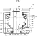
- FIGS. 1 to 3 show cross-sectional views of the rotational positioning device 100.
- the rotational positioning device 100 includes: a housing 101; a rotational member 102 rotatable about a rotational member axial line 103; and at least one sensor 104, installed in the housing 101, serving as an angle detector.
- the rotational member 102 is entirely accommodated in the housing 101, at least a part of the rotational member 102 may be accommodated in the housing 101.
- a graduated scale 105 having a plurality of scale marks is integrally formed with the rotational member 102 along the circumferential direction of the rotational member 102.
- the scale marks of the graduated scale 105 may be formed integrally with the rotational member 102 in the radial direction with respect to the rotational member axial line 103 along the circumferential direction of the rotational member 102.
- the scale marks of the graduated scale 105 may be integrally formed with the rotational member 102 in a direction parallel to the rotational member axial line 103.
- the scale marks may be formed integrally with the rotational member 102 in a gear shape, or may be a linearly engraved rotational member 102.
- the scale marks are not limited to ones that can be visually recognized, and any scale marks may be used as long as they allow the sensor 104 to read a predetermined positional interval on the graduated scale 105 as an interval for one scale mark.
- the graduated scale 105 may be integrally formed with the rotational member 102 along the circumferential direction of any part of the rotational member 102.
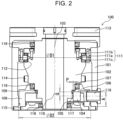
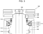
- the graduated scale 105 may be formed on a lower part of the rotational member 102 as shown in FIGS. 1 and 2 , or may be formed on an upper part of the rotational member 102 as shown in FIG. 3 .
- the graduated scale 105 may be formed on a part of the rotational member 102 inside the housing 101 as shown in FIGS. 1 and 2 , or may be formed in a part of the rotational member 102 outside the housing 101 as shown in FIG. 3 .
- a rotational table 113 is provided at the end part of the rotational member 102 serving as the output shaft, as shown in FIGS. 1 to 3 .
- the rotational table 113 rotates accordingly.
- the graduated scale 105 may be integrally formed with a part of the rotational member 102, serving as an output shaft, accommodated in the housing 101.
- the graduated scale 105 may be formed on the lower part of the rotational member 102, or may be formed on the upper part of the rotational member 102.
- the rotational member 102 may be provided with a transmission mechanism 114. Via the transmission mechanism 114, driving force from an input shaft may be transmitted to rotate the rotational member 102 serving as the output shaft. Further, the rotational member 102 may be configured without any transmission mechanism 114. With such a configuration, a driving device such as a motor may be directly connected to the rotational member 102 to rotate the rotational member 102.
- the graduated scale 105 may be integrally formed with a part of the rotational member 102, serving as an output shaft, adjacent to the rotational table 113.
- the graduated scale 105 may be integrally formed with a part of the rotational member 102, serving as an output shaft, between the housing 101 and the rotational table 113.
- forming the graduated scale 105 integrally with the rotational member 102, serving as an output shaft, so as to be adjacent to the rotational table 113 allows detecting the angle change amount of the rotational table 113 with further high precision. Then, this allows positioning the rotational table 113 at the target angle position with high precision.
- the principle of the sensor 104 is not particularly limited as long as the sensor can read the scale marks of the graduated scale 105.
- Examples of the sensor 104 include an optical sensor, a magnetic sensor, a coil, and the like.
- an optical sensor is installed as the sensor 104, in order to change the light reflection state and transmission state, a linearly engraved part on the rotational member 102 may be integrally formed with the rotational member 102 to form scale marks.
- a part configured in a gear shape on the rotational member 102 may be integrally formed with the rotational member 102 to form scale marks.
- the sensor 104 then reads a graduated scale 105 having a plurality of scale marks integrally formed with the rotational member 102 along the circumferential direction of the rotational member 102. Thereby, the angle change amount due to rotation of the rotational member 102 is detected based on the plurality of scale marks.
- integrally forming the graduated scale 105 on the rotational member 102 can reduce the influence of the center deviation due to the graduated scale 105; allows the rotational positioning device 100 to detect the angle change amount of the rotational member 102 with high precision; and then allows the rotational member 102 to be positioned at a target angle position with high precision. In addition, this can make the rotational positioning device 100 compact, reduce the number of parts thereof, and reduce the cost thereof.
- the housing 101 is provided with at least one seat 106 for installing at least one sensor 104.
- the respective seats 106 are provided along the circumferential direction of the rotational member 102.
- the respective seats 106 are also provided so as to be equal in the distance from the rotational member axial line 103 of the rotational member 102, and to be equal in the distance to adjacent seat(s) 106.
- Each of the sensors 104 is installed in any of two or more seats 106. Not all the seats 106 need to have the sensors 104 installed thereon, and there may be a configuration in which only some of the seats 106, as an option, have the sensors 104 installed thereon.
- Each sensor 104 is installed in its corresponding seat 106 to define the position of each sensor 104 with respect to the rotational member 102 and to define a gap 107 (P) between each sensor 104 and the scale marks of the graduated scale 105.
- the seat 106 guarantees a gap 107 (P) and determines the distance of each sensor 104 from the rotational member axial line 103 of the rotational member 102.
- installing two or more sensors 104 determines the distance between two adjacent sensors 104, and guarantees the position (Q) for each sensor 104 to read the scale marks of the graduated scale 105.
- the sensor 104 and the graduated scale 105 are positioned with respect to the rotational member axial line 103 of the rotational member 102. This allows the rotational positioning device 100 to detect the angle change amount of the rotational member 102 with high precision; this then allows the rotational member 102 to be positioned at a target angle position with high precision.
- the rotational positioning device 100 may further include a bearing 111 for supporting the rotation, of the rotational member 102, with respect to the housing 101.
- the raceway surface 112 of the bearing 111 may be integrally formed with the rotational member 102 as shown in FIGS. 1 to 3 .
- the sensor 104, the graduated scale 105, and the bearing 111 are positioned with respect to the rotational member axial line 103 of the rotational member 102. This allows the rotational positioning device 100 to detect the angle change amount of the rotational member 102 with high precision; this then allows the rotational member 102 to be positioned at a target angle position with high precision. Further, as shown in FIG.
- the central axis line of the inner diameter (D1) of the housing 101 part corresponding to the raceway surface 112 is aligned with the rotational member axial line 103 of the rotational member 102.
- the radial bearing 111a, the first thrust bearing 111b, and the second thrust bearing 111c are provided as the bearing 111, the configuration of the bearing is not limited thereto. Any configuration is allowed as long as the raceway surface 112 of the bearing 111 is integrally formed with the rotational member 102.
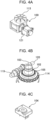
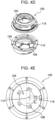
- FIGS. 4A to 4E relate to the rotational positioning device 100 of the embodiment shown in FIG. 1 , in which the rotational member102 is used as an output shaft, and a rotational table 113 is provided at an end part of the rotational member 102 serving as an output shaft.
- the graduated scale 105 has a plurality of scale marks at substantially equal intervals.
- the graduated scale 105 are formed integrally with the rotational member 102 in the radial direction with respect to the rotational member axial line 103 along the circumferential direction of the rotational member 102.
- the rotational positioning device 100 may further include a second rotational member 119 rotatable about a second rotational member axial line 120. In the rotational positioning device 100 of FIG.
- a roller gear cam mechanism having a rotational member 102 serving as an output shaft and a second rotational member 119 serving as an input shaft.
- the second rotational member 119 is a cam that has a screw-shaped cam rib and is rotatable about the second rotational member axial line 120.
- the rotational member 102 is rotatable about the rotational member axial line 103 orthogonal to the second rotational member axial line 120.
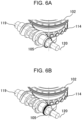
- a plurality of bearings included in the transmission mechanism 114 are arranged on the rotational member 102 along the circumferential direction thereof.
- a motor 121 is connected to the second rotational member 119. The motor 121 is driven to rotate the second rotational member 119 about the second rotational member axial line 120.
- Each of the plurality of bearings included in the transmission mechanism 114 may be in a rolling contact with the cam rib of the second rotational member 119, or may be a roller follower or a cam follower. Further, the plurality of bearings included in the transmission mechanism 114 each include a shaft member, an outer ring part rotatable along the outer peripheral surface of the shaft member, and the like.
- each of the plurality of bearings may be a bearing with rolling contact including rollers and the like between the shaft member and the outer ring part, or may be a bearing with sliding contact not including rollers and the like.
- the shaft member may be directly fitted to the rotational member 102.
- the second rotational member 119 serving as the input shaft is a drum-shaped cam, it may be a cylindrical cam (barrel cam) or a globoidal cam. Further, the second rotational member 119 serving as the input shaft and the rotational member 102 serving as the output shaft are in a circumscribed positional relationship. However, depending on the shape of the cam of the second rotational member 119 serving as the input shaft, the one rotational member may be in an inscribed positional relationship to the other rotational member. Further, the roller gear cam mechanism is employed in the rotational positioning device 100 of FIG. 4B . However, any mechanism is allowed as long as it can transmit the input torque of the second rotational member 119 to the rotational member 102 via the transmission mechanism 114. For example, a barrel cam mechanism may be employed, or a gear mechanism may be employed.
- At least one seat 106 may be provided in the housing 101 via a sensor flange 108 shown in FIGS. 4D and 4E .
- the sensor 104 is installed in the housing 101 via the seat 106 provided in the sensor flange 108.
- FIG. 4C shows the shape of the sensor 104 to be installed on the seat 106 of the sensor flange 108.
- the sensor flange 108 is provided with a rotational member hole 109 for passing at least a part of the rotational member 102. As shown in FIG. 1 , the central axis line 110 of the rotational member hole 109 is aligned with the rotational member axial line 103 of the rotational member 102.
- the central axis line of the inner diameter (D2) of the housing 101 part corresponding to the sensor flange 108 is also aligned with the rotational member axial line 103 of the rotational member 102, as shown in FIG. 1 .
- the central axis line of the inner diameter (D2) is also aligned with the central axis line 110 of the rotational member hole 109.
- the sensor flange 108 defines the distance (A) from this installation surface to the sensor 104 installed on the sensor flange 108, and guarantees a gap 107 (P). Further, the sensor flange 108 defines the distance (B) of the seat 106 from the central axis line 110 of the rotational member hole 109. The sensor flange 108 also defines the position (C) of the seat 106 in the circumferential direction of the rotational member hole 109. Thereby, the sensor flange 108 guarantees the position (Q) in which the sensor 104 reads the scale marks of the graduated scale 105. Further, the sensor flange 108 may be provided with a cable hole 118. Then, a cable may be connected to the sensor 104 via the cable hole 118 to receive a signal, detected by the sensor 104, regarding the angle change amount due to rotation of the rotational member 102.
- the housing 101 may be provided with a seal flange 115. Then, the sensor flange 108 and the seal flange 115 may provide a sensor and cable installation space 117 therebetween.
- a seal 116 may be provided between the rotational member 102 and the sensor flange 108 to prevent the lubricant from entering the sensor and cable installation space 117. Alternatively, the seal 116 may be provided between the rotational member 102 and the seal flange 115 to isolate the sensor and cable installation space 117 from the external space.
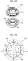
- FIGS. 5A-5E relate to the rotational positioning device 100 of the embodiment shown in FIG. 2 , and are substantially the same as those of FIGS. 4A-4E .
- the different point is, as shown in FIG. 5B , that a graduated scale 105, having a plurality of scale marks at substantially equal intervals, is formed integrally with the rotational member 102 in a direction parallel to the rotational member axial line 103 along the circumferential direction of the rotational member 102.
- the shape of the sensor flange 108 is changed as shown in FIGS. 5D and 5E
- the shape of the sensor 104 is changed as shown in FIG. 5C .
- the rotational positioning device 100 may be capable of detecting the angle change amount due to the rotation of the rotational table 113 for loading the machining works and the like of the machine tool. Therefore, the graduated scale 105 may be integrally formed with the second rotational member 119 serving as the input shaft shown in FIGS. 4D and 5D .
- the rotational positioning device 100 includes: a housing 101; a second rotational member 119 rotatable about a second rotational member axial line 120; and at least one sensor 104 serving as an angle detector installed in the housing 101.
- a graduated scale 105 having a plurality of scale marks is integrally formed with the second rotational member 119 along the circumferential direction of the second rotational member 119.
- the scale marks of the graduated scale 105 may be formed integrally with the second rotational member 119 in the radial direction with respect to the second rotational member axial line 120 along the circumferential direction of the second rotational member 119.
- the scale marks may be integrally formed with the second rotational member 119 in a direction parallel to the second rotational member axial line 120.
- the rotational positioning device 100 further includes a rotational member 102 serving as an output shaft rotatable about a rotational member axial line 103.
- a transmission mechanism 114 is installed on the rotational member 102, serving as an output shaft, along the circumferential direction of the rotational member 102.
- the second rotational member 119 serving as the input shaft, is in contact with the transmission mechanism 114. Therefore, as the second rotational member 119 rotates, the rotational member 102 serving as the output shaft can rotate.
- the rotational member 102 does not necessarily need a graduated scale 105 formed thereon, and both the rotational member 102 and the second rotational member 119 may have the graduated scales 105 formed thereon.
- integrally forming the graduated scale 105 on the input shaft can reduce the size of the rotational positioning device 100.
- installing an angle detector on the input shaft allows a lower precision than installing an angle detector on the output shaft.
- the reduction ratio between the input shaft and the output shaft is 16 and the target positioning precision of the output shaft is 22 bits (360°/2 22 )
- installing an angle detector on the output shaft directly needs 22-bit precision.
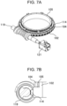
- FIGS. 7A and 7B each show an enlarged view of the inside of the rotational positioning device 100 according to the embodiment shown in FIG. 2 .
- the size of the rotational positioning device 100 is changed according to the application. However, regardless of the size, the rotational positioning device 100 just has a graduated scale 105 formed integrally with the rotational member 102, and a sensor 104 installed along the circumferential direction of the rotational member 102, in the same manner as the above described. This allows creating a rotational positioning device 100 that is not limited in size.
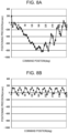
- FIG. 8A shows an example of positioning precision with respect to a command position when there is no center deviation between the rotational member 102 and the graduated scale 105.
- FIG. 8B shows an example of positioning precision with respect to the command position when there is a center deviation between the rotational member 102 and the graduated scale 105.
- the positioning precision is based on the command position, which is the target angle position of the rotational member 102 serving as an output shaft. Specifically, the positioning precision has improved by about 600 arcsec, from a maximum of about 800 arcsec to a maximum of about 200 arcsec.
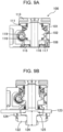
- FIG. 9A is a cross-sectional view of a rotational positioning device 100 having: a graduated scale 105 integrally formed with a part of the rotational member 102 accommodated in a housing 101; and a sensor 104 installed in a sensor and cable installation space 117 in the housing 101.
- FIG. 9B shows a rotational positioning device when an angle detector is externally attached.
- an external encoder 122 serving as an angle detector is fixed to a housing via an installation base 123.
- the external encoder 122 has a fitting shaft 126 connected to an output shaft via an encoder collar 124 and an extension flange 125.
- the sensor 104 is installed and the graduated scale 105 is formed, in the space which is a dead space in the conventional configuration. This can make the rotational positioning device 100 more compact than the conventional one, reduce the number of parts, and reduce the cost.
- the rotational positioning device 100 may employ the angle detector that is an angle detector with a self-calibration function as disclosed in Patent Literature 3 to 5.
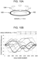
- One angle detector with a self-calibration function as shown in FIG. 10A due to its configuration, has a plurality of sensors 104 arranged along the circumferential direction of the rotational member 102.
- Each of the plurality of sensors 104 reads a graduated scale 105 having a plurality of scale marks integrally formed with the rotational member 102 in the radial direction with respect to the rotational member axial line 103 along the circumferential direction of the rotational member 102.
- the angle change amount due to rotation of the rotational member 102 is detected based on the plurality of scale marks.
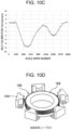
- FIG. 10B shows the positioning precision for scale mark numbers calculated from the angle change amount detected by each of the plurality of sensors 104. Based on the angle change amount detected by each of the plurality of sensors 104, there is calculated a calibration curve that eliminates the angle error shown in FIG. 10C . Then, the angle error based on this calibration curve is subtracted from the angle change amount of one representative sensor 104, so that there can be calculated the true angle change amount due to the rotation of the rotational table 113.
- employing the angle detector with a self-calibration function allows detecting the angle change amount of the rotational table 113 with high precision. Then, this allows positioning the rotational table 113 at the target angle position with high precision. Note that although the number of sensors is eight in FIG. 10A , the number may be two or more.
- FIG. 10D another angle detector with a self-calibration function as shown in FIG. 10D has, due to its configuration, a plurality of sensors 104 arranged along the circumferential direction of the rotational member 102.
- Each of the plurality of sensors 104 reads a graduated scale 105 having a plurality of scale marks integrally formed with the rotational member 102 in the direction parallel to the rotational member axial line 103 along the circumferential direction of the rotational member 102.
- the angle detector with a self-calibration function as shown in FIG. 10D can also obtain the same result as in FIGS. 10B and 10C . Note that although the number of sensors is five in FIG. 10D , the number may be two or more.
- FIG. 11A shows an example of a positioning control method using a rotational positioning device 100 in which a graduated scale 105 is formed integrally with a rotational member 102 serving as an output shaft.
- FIG. 11B shows an example of a positioning control method using a rotational positioning device 100 in which a graduated scale 105 is integrally formed with a second rotational member 119 serving as an input shaft.
- the rotational positioning device 100 when the input shaft rotates as shown by an arrow, the rotational angle of the input shaft is transmitted, the output shaft rotates as shown by an arrow, and a rotational table 113 also rotates accordingly.
- a sensor 104 serving as an angle detector detects the angle change amount due to the rotation of the output shaft or the input shaft based on a plurality of scale marks of the graduated scale 105.
- the angle change amount is communicated to a controller or driver 127 for driving a motor 121 as a reference angle for positioning the rotational table 113.
- the controller or driver 127 controls the motor 121 according to the difference between the target angle position and the reference angle, and positions the rotational table 113 at the target angle position with high precision.
Landscapes
- Engineering & Computer Science (AREA)
- General Engineering & Computer Science (AREA)
- Mechanical Engineering (AREA)
- Physics & Mathematics (AREA)
- General Physics & Mathematics (AREA)
- Transmission And Conversion Of Sensor Element Output (AREA)
- Length Measuring Devices With Unspecified Measuring Means (AREA)
Claims (8)
- Eine Drehpositioniervorrichtung (100), umfassend:ein Gehäuse (101);ein Drehelement (102), das um eine Axiallinie (103) des Drehelements drehbar ist, wobei mindestens ein Teil des Drehelements (102) im Gehäuse (101) aufgenommen ist; undmindestens einen Sensor (104), der im Gehäuse installiert ist, wobei, um das Drehelement (102) zu drehen, ein Motor mit dem Drehelement (102) verbunden ist, oder das Drehelement (102) einen Getriebemechanismus (114) aufweist, der entlang einer Umfangsrichtung des Drehelements (102) installiert ist, wobei Antriebskraft über den Getriebemechanismus (114) auf das Drehelement (102) übertragen wird; undwobei eine Messskala (105), die eine Vielzahl von Skalenmarkierungen aufweist, entlang einer Umfangsrichtung des Drehelements (102) in einem Stück mit dem Drehelement (102) gebildet ist, der mindestens eine Sensor (104) einen Winkeländerungsbetrag aufgrund einer Drehung des Drehelements (102) auf Basis der Vielzahl von Skalenmarkierungen erkennt, und das Drehelement (102) auf Basis des Winkeländerungsbetrags in einer Zielwinkelposition zu positionieren ist,dadurch gekennzeichnet, dass die Drehpositioniervorrichtung (100) weiter einen Sensorflansch (108) umfasst, der im Gehäuse (101) installiert ist, wobei im Sensorflansch (108) ein kreisförmiges Drehelementloch (109) bereitgestellt ist, wobei der mindestens eine Sensor (104) am Sensorflansch (108) installiert ist;wobei mindestens ein Abschnitt des Drehelements (102) innerhalb des Drehelementlochs (109) untergebracht ist, wobei eine Mittelachsenlinie (110) des Drehelementlochs (109) mit der Axiallinie (103) des Drehelements ausgerichtet ist, sodass eine Position des mindestens einen Sensors (104) zur Messskala (105) bestimmt wird; undwobei eine erste Dichtung (116) zwischen dem Sensorflansch (108) und dem Drehelement (102) bereitgestellt ist, um zu verhindern, dass ein Schmiermittel in einen Raum (117), in dem der mindestens eine Sensor (104) installiert ist, eindringt.
- Die Drehpositioniervorrichtung (100) nach Anspruch 1, wobei die Messskala (105) in einer radialen Richtung in Bezug auf die Axiallinie (103) des Drehelements oder einer Richtung parallel zur Axiallinie (103) des Drehelements in einem Stück mit dem Drehelement (102) gebildet ist.
- Die Drehpositioniervorrichtung (100) nach Anspruch 1 oder 2, wobei mindestens ein Sitz (106) am Sensorflansch (108) bereitgestellt ist, und jeder von dem mindestens einen Sensor (104) in einem entsprechenden Sitz (106) eines jeden Sensors (104) installiert ist, um eine Position eines jeden Sensors (104) und einen Spalt (107) zwischen jedem Sensor (104) und den Skalenmarkierungen zu definieren.
- Die Drehpositioniervorrichtung (100) nach einem der Ansprüche 1 bis 3, die weiter einen Dichtungsflansch (115) umfasst, der im Gehäuse (101) installiert ist, wobei eine zweite Dichtung (116) zwischen dem Dichtungsflansch (115) und dem Drehelement (102) bereitgestellt ist, um den Raum (117) von einem Außenraum zu isolieren.
- Die Drehpositioniervorrichtung (100) nach Anspruch 3, wobei der mindestens eine Sitz (106) zwei oder mehr Sitze (106) sind, die entlang der Umfangsrichtung des Drehelements (102) bereitgestellt sind, wobei die zwei oder mehr Sitze (106) bereitgestellt sind, sodass Abstände von der Axiallinie (103) des Drehelements gleich sind und Abstände zwischen benachbarten Sitzen (106) gleich sind, wobei der mindestens eine Sensor (104) zwei oder mehr Sensoren (104) sind, und jeder der zwei oder mehr Sensoren (104) in einem der zwei oder mehr Sitze (106) installiert ist.
- Die Drehpositioniervorrichtung (100) nach einem der Ansprüche 1 bis 5, die weiter ein Lager (111) zum Unterstützen einer Drehung des Drehelements (102) in Bezug auf das Gehäuse (101) umfasst, wobei eine Laufbahnoberfläche (112) des Lagers (111) in einem Stück mit dem Drehelement (102) gebildet ist.
- Die Drehpositioniervorrichtung (100) nach einem der Ansprüche 1 bis 6, wobei die Messskala (105) in einem Stück mit einem Teil des im Gehäuse (101) aufgenommenen Drehelements (102) gebildet ist.
- Die Drehpositioniervorrichtung (100) nach einem der Ansprüche 1 bis 7, wobei das Drehelement (102) eine Abtriebswelle ist, ein Drehtisch (113) an einem Endteil der Abtriebswelle bereitgestellt ist, und die Messskala (105) in einem Stück mit einem Teil der Abtriebswelle gebildet ist, wobei der Teil benachbart zum Drehtisch (113) ist.
Applications Claiming Priority (2)
| Application Number | Priority Date | Filing Date | Title |
|---|---|---|---|
| JP2019203234 | 2019-11-08 | ||
| PCT/JP2020/031647 WO2021090551A1 (ja) | 2019-11-08 | 2020-08-21 | 回転位置決め装置 |
Publications (3)
| Publication Number | Publication Date |
|---|---|
| EP4056313A1 EP4056313A1 (de) | 2022-09-14 |
| EP4056313A4 EP4056313A4 (de) | 2023-10-11 |
| EP4056313B1 true EP4056313B1 (de) | 2024-10-16 |
Family
ID=75849831
Family Applications (1)
| Application Number | Title | Priority Date | Filing Date |
|---|---|---|---|
| EP20883796.3A Active EP4056313B1 (de) | 2019-11-08 | 2020-08-21 | Drehpositioniervorrichtung |
Country Status (7)
| Country | Link |
|---|---|
| US (1) | US12304020B2 (de) |
| EP (1) | EP4056313B1 (de) |
| JP (1) | JP7592612B2 (de) |
| KR (1) | KR102836005B1 (de) |
| CN (1) | CN114555290A (de) |
| TW (1) | TWI860404B (de) |
| WO (1) | WO2021090551A1 (de) |
Families Citing this family (4)
| Publication number | Priority date | Publication date | Assignee | Title |
|---|---|---|---|---|
| TWI771530B (zh) * | 2018-01-31 | 2022-07-21 | 日商三共製作所股份有限公司 | 凸輪裝置 |
| JP7322095B2 (ja) | 2021-05-27 | 2023-08-07 | 日本トムソン株式会社 | 回転テーブル |
| CN115388278B (zh) * | 2022-08-12 | 2024-05-14 | 贵州电网有限责任公司 | 一种用于变电站伸缩旋转支架的旋转限位机构 |
| CN117804519B (zh) * | 2024-01-03 | 2024-09-06 | 重庆日联科技有限公司 | 一种x射线检测设备重复定位精度调整设备及方法 |
Citations (2)
| Publication number | Priority date | Publication date | Assignee | Title |
|---|---|---|---|---|
| DE102009001212A1 (de) * | 2009-02-27 | 2010-09-02 | Dr. Johannes Heidenhain Gmbh | Baueinheit für eine Winkelmesseinrichtung und entsprechende Winkelmesseinrichtung |
| US20100301847A1 (en) * | 2008-02-07 | 2010-12-02 | Ntn Corporation | Wheel bearing device with rotation detector |
Family Cites Families (26)
| Publication number | Priority date | Publication date | Assignee | Title |
|---|---|---|---|---|
| US4080849A (en) * | 1976-12-13 | 1978-03-28 | Erickson Tool Company | Precision heavy duty indexer |
| JP3255508B2 (ja) | 1993-09-17 | 2002-02-12 | 有限会社リブレット | 回転間欠割出装置 |
| US5508806A (en) | 1995-02-13 | 1996-04-16 | Hewlett-Packard Company | Apparatus and method for making rotary calibrations of a machine tool table |
| JP3515928B2 (ja) | 1998-09-24 | 2004-04-05 | 高広工業株式会社 | ローラタレットおよびその製造方法 |
| JP2004160642A (ja) | 2002-10-22 | 2004-06-10 | Sankyo Mfg Co Ltd | 傾斜回動テーブル装置 |
| JP4320241B2 (ja) * | 2003-11-07 | 2009-08-26 | 津田駒工業株式会社 | インデックステーブル |
| JP3826207B2 (ja) | 2004-08-31 | 2006-09-27 | 独立行政法人産業技術総合研究所 | 自己校正機能付き角度検出器 |
| JP4590244B2 (ja) * | 2004-10-15 | 2010-12-01 | 株式会社三共製作所 | 回転テーブル装置 |
| WO2007111261A1 (ja) | 2006-03-27 | 2007-10-04 | Pioneer Corporation | 電子ビーム記録装置及びビーム調整方法 |
| TW200821083A (en) * | 2006-10-26 | 2008-05-16 | Tsudakoma Ind Co Ltd | Angle indexing device for machine tool |
| JP5116135B2 (ja) * | 2006-11-14 | 2013-01-09 | 津田駒工業株式会社 | インデックステーブル |
| JP5216528B2 (ja) | 2008-10-24 | 2013-06-19 | 津田駒工業株式会社 | 工作機械用の割出し装置におけるクランプ装置 |
| JP2009148840A (ja) * | 2007-12-19 | 2009-07-09 | Tsudakoma Corp | 工作機械用の回転割出テーブル装置 |
| JP5132398B2 (ja) | 2008-04-10 | 2013-01-30 | 株式会社リコー | パルスコードホイールの製造方法、パルスコードホイール、ロータリーエンコーダ、回転制御装置、ベルト搬送装置、及び画像形成装置 |
| CN102132126B (zh) | 2008-08-26 | 2015-04-08 | 株式会社尼康 | 编码器系统、信号处理方法 |
| DE102009023079A1 (de) * | 2009-05-28 | 2010-12-02 | Weiß GmbH Sondermaschinentechnik | Rundschalttisch |
| JP4984269B2 (ja) | 2009-11-09 | 2012-07-25 | 独立行政法人産業技術総合研究所 | 複合自己校正機能付き角度検出器 |
| JP4984268B2 (ja) | 2009-11-09 | 2012-07-25 | 独立行政法人産業技術総合研究所 | 軸ぶれ計測方法及び軸ぶれ計測機能を具備した自己校正機能付き角度検出器 |
| JP2012020378A (ja) * | 2010-07-15 | 2012-02-02 | Tsudakoma Corp | 工作機械用の割り出し装置 |
| CN103221790B (zh) * | 2010-11-18 | 2016-02-03 | 三菱电机株式会社 | 旋转角度检测装置 |
| CN103827637B (zh) * | 2011-07-08 | 2016-02-24 | 卡尔蔡司工业测量技术有限公司 | 旋转装置的校准和运行、尤其是用于使坐标测量仪的探触头和/或探触件旋转的旋转装置的校准和运行 |
| EP2828577B8 (de) | 2012-03-20 | 2017-06-28 | Martin Professional ApS | Beweglicher scheinwerfer mit joch- und kopfposition-kodierungsmittel |
| DE102015221599A1 (de) | 2015-11-04 | 2017-05-04 | Dr. Johannes Heidenhain Gmbh | Werkzeugmaschine |
| JP6651962B2 (ja) | 2016-04-12 | 2020-02-19 | 株式会社デンソー | 位置検出装置 |
| DE102017118262A1 (de) * | 2017-08-10 | 2019-02-14 | Weiss Gmbh | Rundschalttisch mit kraft-optimiertem antrieb |
| WO2019216235A1 (ja) * | 2018-05-11 | 2019-11-14 | 株式会社三共製作所 | 角度検出器 |
-
2020
- 2020-08-21 JP JP2021554824A patent/JP7592612B2/ja active Active
- 2020-08-21 CN CN202080071474.9A patent/CN114555290A/zh active Pending
- 2020-08-21 WO PCT/JP2020/031647 patent/WO2021090551A1/ja not_active Ceased
- 2020-08-21 US US17/773,472 patent/US12304020B2/en active Active
- 2020-08-21 KR KR1020227015270A patent/KR102836005B1/ko active Active
- 2020-08-21 EP EP20883796.3A patent/EP4056313B1/de active Active
- 2020-09-15 TW TW109131734A patent/TWI860404B/zh active
Patent Citations (2)
| Publication number | Priority date | Publication date | Assignee | Title |
|---|---|---|---|---|
| US20100301847A1 (en) * | 2008-02-07 | 2010-12-02 | Ntn Corporation | Wheel bearing device with rotation detector |
| DE102009001212A1 (de) * | 2009-02-27 | 2010-09-02 | Dr. Johannes Heidenhain Gmbh | Baueinheit für eine Winkelmesseinrichtung und entsprechende Winkelmesseinrichtung |
Also Published As
| Publication number | Publication date |
|---|---|
| JP7592612B2 (ja) | 2024-12-02 |
| TWI860404B (zh) | 2024-11-01 |
| KR20220090521A (ko) | 2022-06-29 |
| CN114555290A (zh) | 2022-05-27 |
| US12304020B2 (en) | 2025-05-20 |
| KR102836005B1 (ko) | 2025-07-18 |
| EP4056313A1 (de) | 2022-09-14 |
| TW202118579A (zh) | 2021-05-16 |
| EP4056313A4 (de) | 2023-10-11 |
| US20220347807A1 (en) | 2022-11-03 |
| JPWO2021090551A1 (de) | 2021-05-14 |
| WO2021090551A1 (ja) | 2021-05-14 |
Similar Documents
| Publication | Publication Date | Title |
|---|---|---|
| EP4056313B1 (de) | Drehpositioniervorrichtung | |
| US8502528B2 (en) | Arrangement for detecting a rotation angle | |
| JP4912212B2 (ja) | 舵取機の舵角検出装置 | |
| JP4875111B2 (ja) | 角度位置を検出する検出装置、電動機、ステアリングコラムおよび減速装置 | |
| US6248993B1 (en) | Steering angle sensor | |
| US20100064822A1 (en) | Device fhor detecting torque transmitted by a shaft | |
| CN102338165B (zh) | 监测转台轴承角位移的反射式控制方法 | |
| US20200055361A1 (en) | Gearing arrangement for an actuator device for height adjustment of a vehicle body | |
| JPH02300519A (ja) | ラジアル転がり軸受け | |
| JPWO2021090551A5 (de) | ||
| CN213999484U (zh) | 转动关节组件 | |
| EP2546613B1 (de) | Verfahren zum Ausarbeiten der Exzentrizität und der Winkelposition eines rotierenden Elements und Vorrichtung zur Durchführung solch eines Verfahrens | |
| KR20050093791A (ko) | 센서를 구비하는 구름 베어링 유닛 | |
| JP2008538415A (ja) | ねじりモーメントの測定装置および方法 | |
| JP7464446B2 (ja) | 角度測定機構および角度測定機構の動作方法 | |
| JP7517880B2 (ja) | 角度測定装置 | |
| EP3941870B1 (de) | System zur messung der positionierung eines objekts in bezug auf einen festen referenz | |
| JP2003214845A (ja) | 自動車ハンドルのステアリング角決定装置 | |
| US7041961B2 (en) | Device for measurement of rotational angle of two components relative to each other | |
| US11274941B2 (en) | Device and method for determining a total pitch deviation of an annular product | |
| EP1783461A1 (de) | Lager mit absolutwinkelsensor | |
| CN212585681U (zh) | 一种方向盘转角传感器测试台架 | |
| EP1961585B1 (de) | Tragevorrichtung für eine Achse und Herstellungsverfahren dafür | |
| EP4025917A1 (de) | Achsanordnung und fahrzeug mit einer solchen achsanordnung | |
| US20230347978A1 (en) | Rotary Position Sensor |
Legal Events
| Date | Code | Title | Description |
|---|---|---|---|
| STAA | Information on the status of an ep patent application or granted ep patent |
Free format text: STATUS: THE INTERNATIONAL PUBLICATION HAS BEEN MADE |
|
| PUAI | Public reference made under article 153(3) epc to a published international application that has entered the european phase |
Free format text: ORIGINAL CODE: 0009012 |
|
| STAA | Information on the status of an ep patent application or granted ep patent |
Free format text: STATUS: REQUEST FOR EXAMINATION WAS MADE |
|
| 17P | Request for examination filed |
Effective date: 20220510 |
|
| AK | Designated contracting states |
Kind code of ref document: A1 Designated state(s): AL AT BE BG CH CY CZ DE DK EE ES FI FR GB GR HR HU IE IS IT LI LT LU LV MC MK MT NL NO PL PT RO RS SE SI SK SM TR |
|
| DAV | Request for validation of the european patent (deleted) | ||
| DAX | Request for extension of the european patent (deleted) | ||
| A4 | Supplementary search report drawn up and despatched |
Effective date: 20230912 |
|
| RIC1 | Information provided on ipc code assigned before grant |
Ipc: G01D 5/347 20060101ALI20230906BHEP Ipc: G01D 5/244 20060101ALI20230906BHEP Ipc: G01D 18/00 20060101ALI20230906BHEP Ipc: F16C 41/00 20060101ALI20230906BHEP Ipc: F16C 33/58 20060101ALI20230906BHEP Ipc: F16C 19/54 20060101ALI20230906BHEP Ipc: F16C 19/30 20060101ALI20230906BHEP Ipc: F16C 19/26 20060101ALI20230906BHEP Ipc: B23Q 17/22 20060101ALI20230906BHEP Ipc: B23Q 16/02 20060101ALI20230906BHEP Ipc: G01D 5/245 20060101ALI20230906BHEP Ipc: F16H 1/16 20060101ALI20230906BHEP Ipc: F16C 33/02 20060101ALI20230906BHEP Ipc: F16C 19/14 20060101ALI20230906BHEP Ipc: B23Q 17/00 20060101ALI20230906BHEP Ipc: B23Q 1/52 20060101AFI20230906BHEP |
|
| GRAP | Despatch of communication of intention to grant a patent |
Free format text: ORIGINAL CODE: EPIDOSNIGR1 |
|
| STAA | Information on the status of an ep patent application or granted ep patent |
Free format text: STATUS: GRANT OF PATENT IS INTENDED |
|
| INTG | Intention to grant announced |
Effective date: 20240516 |
|
| GRAS | Grant fee paid |
Free format text: ORIGINAL CODE: EPIDOSNIGR3 |
|
| GRAA | (expected) grant |
Free format text: ORIGINAL CODE: 0009210 |
|
| STAA | Information on the status of an ep patent application or granted ep patent |
Free format text: STATUS: THE PATENT HAS BEEN GRANTED |
|
| AK | Designated contracting states |
Kind code of ref document: B1 Designated state(s): AL AT BE BG CH CY CZ DE DK EE ES FI FR GB GR HR HU IE IS IT LI LT LU LV MC MK MT NL NO PL PT RO RS SE SI SK SM TR |
|
| REG | Reference to a national code |
Ref country code: GB Ref legal event code: FG4D |
|
| REG | Reference to a national code |
Ref country code: CH Ref legal event code: EP |
|
| REG | Reference to a national code |
Ref country code: IE Ref legal event code: FG4D |
|
| REG | Reference to a national code |
Ref country code: DE Ref legal event code: R096 Ref document number: 602020039716 Country of ref document: DE |
|
| REG | Reference to a national code |
Ref country code: LT Ref legal event code: MG9D |
|
| REG | Reference to a national code |
Ref country code: NL Ref legal event code: MP Effective date: 20241016 |
|
| REG | Reference to a national code |
Ref country code: AT Ref legal event code: MK05 Ref document number: 1732571 Country of ref document: AT Kind code of ref document: T Effective date: 20241016 |
|
| PG25 | Lapsed in a contracting state [announced via postgrant information from national office to epo] |
Ref country code: NL Free format text: LAPSE BECAUSE OF FAILURE TO SUBMIT A TRANSLATION OF THE DESCRIPTION OR TO PAY THE FEE WITHIN THE PRESCRIBED TIME-LIMIT Effective date: 20241016 |
|
| PG25 | Lapsed in a contracting state [announced via postgrant information from national office to epo] |
Ref country code: NL Free format text: LAPSE BECAUSE OF FAILURE TO SUBMIT A TRANSLATION OF THE DESCRIPTION OR TO PAY THE FEE WITHIN THE PRESCRIBED TIME-LIMIT Effective date: 20241016 |
|
| PG25 | Lapsed in a contracting state [announced via postgrant information from national office to epo] |
Ref country code: HR Free format text: LAPSE BECAUSE OF FAILURE TO SUBMIT A TRANSLATION OF THE DESCRIPTION OR TO PAY THE FEE WITHIN THE PRESCRIBED TIME-LIMIT Effective date: 20241016 Ref country code: IS Free format text: LAPSE BECAUSE OF FAILURE TO SUBMIT A TRANSLATION OF THE DESCRIPTION OR TO PAY THE FEE WITHIN THE PRESCRIBED TIME-LIMIT Effective date: 20250216 Ref country code: PT Free format text: LAPSE BECAUSE OF FAILURE TO SUBMIT A TRANSLATION OF THE DESCRIPTION OR TO PAY THE FEE WITHIN THE PRESCRIBED TIME-LIMIT Effective date: 20250217 |
|
| PG25 | Lapsed in a contracting state [announced via postgrant information from national office to epo] |
Ref country code: FI Free format text: LAPSE BECAUSE OF FAILURE TO SUBMIT A TRANSLATION OF THE DESCRIPTION OR TO PAY THE FEE WITHIN THE PRESCRIBED TIME-LIMIT Effective date: 20241016 |
|
| PG25 | Lapsed in a contracting state [announced via postgrant information from national office to epo] |
Ref country code: BG Free format text: LAPSE BECAUSE OF FAILURE TO SUBMIT A TRANSLATION OF THE DESCRIPTION OR TO PAY THE FEE WITHIN THE PRESCRIBED TIME-LIMIT Effective date: 20241016 |
|
| PG25 | Lapsed in a contracting state [announced via postgrant information from national office to epo] |
Ref country code: ES Free format text: LAPSE BECAUSE OF FAILURE TO SUBMIT A TRANSLATION OF THE DESCRIPTION OR TO PAY THE FEE WITHIN THE PRESCRIBED TIME-LIMIT Effective date: 20241016 |
|
| PG25 | Lapsed in a contracting state [announced via postgrant information from national office to epo] |
Ref country code: NO Free format text: LAPSE BECAUSE OF FAILURE TO SUBMIT A TRANSLATION OF THE DESCRIPTION OR TO PAY THE FEE WITHIN THE PRESCRIBED TIME-LIMIT Effective date: 20250116 |
|
| PG25 | Lapsed in a contracting state [announced via postgrant information from national office to epo] |
Ref country code: AT Free format text: LAPSE BECAUSE OF FAILURE TO SUBMIT A TRANSLATION OF THE DESCRIPTION OR TO PAY THE FEE WITHIN THE PRESCRIBED TIME-LIMIT Effective date: 20241016 Ref country code: LV Free format text: LAPSE BECAUSE OF FAILURE TO SUBMIT A TRANSLATION OF THE DESCRIPTION OR TO PAY THE FEE WITHIN THE PRESCRIBED TIME-LIMIT Effective date: 20241016 Ref country code: GR Free format text: LAPSE BECAUSE OF FAILURE TO SUBMIT A TRANSLATION OF THE DESCRIPTION OR TO PAY THE FEE WITHIN THE PRESCRIBED TIME-LIMIT Effective date: 20250117 |
|
| PG25 | Lapsed in a contracting state [announced via postgrant information from national office to epo] |
Ref country code: PL Free format text: LAPSE BECAUSE OF FAILURE TO SUBMIT A TRANSLATION OF THE DESCRIPTION OR TO PAY THE FEE WITHIN THE PRESCRIBED TIME-LIMIT Effective date: 20241016 |
|
| PG25 | Lapsed in a contracting state [announced via postgrant information from national office to epo] |
Ref country code: RS Free format text: LAPSE BECAUSE OF FAILURE TO SUBMIT A TRANSLATION OF THE DESCRIPTION OR TO PAY THE FEE WITHIN THE PRESCRIBED TIME-LIMIT Effective date: 20250116 |
|
| PG25 | Lapsed in a contracting state [announced via postgrant information from national office to epo] |
Ref country code: SM Free format text: LAPSE BECAUSE OF FAILURE TO SUBMIT A TRANSLATION OF THE DESCRIPTION OR TO PAY THE FEE WITHIN THE PRESCRIBED TIME-LIMIT Effective date: 20241016 |
|
| PG25 | Lapsed in a contracting state [announced via postgrant information from national office to epo] |
Ref country code: DK Free format text: LAPSE BECAUSE OF FAILURE TO SUBMIT A TRANSLATION OF THE DESCRIPTION OR TO PAY THE FEE WITHIN THE PRESCRIBED TIME-LIMIT Effective date: 20241016 |
|
| REG | Reference to a national code |
Ref country code: DE Ref legal event code: R097 Ref document number: 602020039716 Country of ref document: DE |
|
| PG25 | Lapsed in a contracting state [announced via postgrant information from national office to epo] |
Ref country code: EE Free format text: LAPSE BECAUSE OF FAILURE TO SUBMIT A TRANSLATION OF THE DESCRIPTION OR TO PAY THE FEE WITHIN THE PRESCRIBED TIME-LIMIT Effective date: 20241016 |
|
| PG25 | Lapsed in a contracting state [announced via postgrant information from national office to epo] |
Ref country code: RO Free format text: LAPSE BECAUSE OF FAILURE TO SUBMIT A TRANSLATION OF THE DESCRIPTION OR TO PAY THE FEE WITHIN THE PRESCRIBED TIME-LIMIT Effective date: 20241016 |
|
| PG25 | Lapsed in a contracting state [announced via postgrant information from national office to epo] |
Ref country code: SK Free format text: LAPSE BECAUSE OF FAILURE TO SUBMIT A TRANSLATION OF THE DESCRIPTION OR TO PAY THE FEE WITHIN THE PRESCRIBED TIME-LIMIT Effective date: 20241016 |
|
| PG25 | Lapsed in a contracting state [announced via postgrant information from national office to epo] |
Ref country code: CZ Free format text: LAPSE BECAUSE OF FAILURE TO SUBMIT A TRANSLATION OF THE DESCRIPTION OR TO PAY THE FEE WITHIN THE PRESCRIBED TIME-LIMIT Effective date: 20241016 |
|
| PG25 | Lapsed in a contracting state [announced via postgrant information from national office to epo] |
Ref country code: IT Free format text: LAPSE BECAUSE OF FAILURE TO SUBMIT A TRANSLATION OF THE DESCRIPTION OR TO PAY THE FEE WITHIN THE PRESCRIBED TIME-LIMIT Effective date: 20241016 |
|
| PLBE | No opposition filed within time limit |
Free format text: ORIGINAL CODE: 0009261 |
|
| STAA | Information on the status of an ep patent application or granted ep patent |
Free format text: STATUS: NO OPPOSITION FILED WITHIN TIME LIMIT |
|
| PG25 | Lapsed in a contracting state [announced via postgrant information from national office to epo] |
Ref country code: SE Free format text: LAPSE BECAUSE OF FAILURE TO SUBMIT A TRANSLATION OF THE DESCRIPTION OR TO PAY THE FEE WITHIN THE PRESCRIBED TIME-LIMIT Effective date: 20241016 |
|
| 26N | No opposition filed |
Effective date: 20250717 |
|
| PGFP | Annual fee paid to national office [announced via postgrant information from national office to epo] |
Ref country code: DE Payment date: 20250827 Year of fee payment: 6 |