EP4053022B1 - Fluggastbrücke - Google Patents
Fluggastbrücke Download PDFInfo
- Publication number
- EP4053022B1 EP4053022B1 EP19950887.0A EP19950887A EP4053022B1 EP 4053022 B1 EP4053022 B1 EP 4053022B1 EP 19950887 A EP19950887 A EP 19950887A EP 4053022 B1 EP4053022 B1 EP 4053022B1
- Authority
- EP
- European Patent Office
- Prior art keywords
- travel
- aircraft
- angle
- undocking
- cab
- Prior art date
- Legal status (The legal status is an assumption and is not a legal conclusion. Google has not performed a legal analysis and makes no representation as to the accuracy of the status listed.)
- Active
Links
Images


Classifications
-
- B—PERFORMING OPERATIONS; TRANSPORTING
- B64—AIRCRAFT; AVIATION; COSMONAUTICS
- B64F—GROUND OR AIRCRAFT-CARRIER-DECK INSTALLATIONS SPECIALLY ADAPTED FOR USE IN CONNECTION WITH AIRCRAFT; DESIGNING, MANUFACTURING, ASSEMBLING, CLEANING, MAINTAINING OR REPAIRING AIRCRAFT, NOT OTHERWISE PROVIDED FOR; HANDLING, TRANSPORTING, TESTING OR INSPECTING AIRCRAFT COMPONENTS, NOT OTHERWISE PROVIDED FOR
- B64F1/00—Ground or aircraft-carrier-deck installations
- B64F1/30—Ground or aircraft-carrier-deck installations for embarking or disembarking passengers
- B64F1/305—Bridges extending between terminal building and aircraft, e.g. telescopic, vertically adjustable
- B64F1/3055—Bridges extending between terminal building and aircraft, e.g. telescopic, vertically adjustable with hinged head interface between aircraft and passenger bridge
Definitions
- the present invention relates to a passenger boarding bridge.
- a passenger boarding bridge that connects between a terminal building and an aircraft is often used for boarding onto and disembarking from the aircraft (see Patent Literature 1, for example).
- Patent Literature 1 describes moving a passenger boarding bridge from a standby position to a predetermined target position, and undocking and moving the passenger boarding bridge from an aircraft to the standby position, by automatic control and/or manual control.
- the passenger boarding bridge includes: a rotunda connected to an entrance of a terminal building and supported in a horizontally rotatable manner; a tunnel unit whose proximal end is connected to the rotunda, the tunnel unit including a plurality of tunnels that are fitted together in a telescopic manner, such that the tunnel unit is extendable and retractable; a cab rotatably provided at the distal end of the tunnel unit and docked with an entrance (door) of the aircraft; and drive columns provided at the distal side of the tunnel unit, the drive columns serving as support legs.
- the drive columns include a lifting/lowering device and a travel device.
- the lifting/lowering device moves the tunnel unit upward/downward.
- the travel device is provided below the lifting/lowering device.
- the travel device includes a pair of travel wheels, each of which can be independently driven to rotate in regular and reverse directions.
- the travel device is configured to travel forward, travel backward, and change the travel direction, by the driving of the travel wheels.
- JP 2004 082833 A discloses a passenger boarding bridge capable of turning with an arbitrary tunnel length.
- JP 2018 187982 A discloses a passenger boarding bridge which moves along a pre-recorded movement path between positions including a retreat position, a standby position, and a connection position.
- JP 2016 172473 A discloses a passenger boarding bridge comprising an attitude correction system.
- JP 2005 104193 A discloses a passenger boarding bridge where movement from a standby position to a determined target position is automated, wherein the target position is defined as an amount of deviation from an actual mounting position of a cab of the passenger boarding bridge to account for when a stop position of an aircraft deviates from a normal position.
- US 2003/145405 A1 discloses a method and apparatus for pre-identifying an approaching aircraft and for automatically pre-positioning a passenger boarding bridge in dependence upon the identification.
- EP 3 814 227 B1 falls within the terms of Art. 54(3) EPC and discloses a method of automated undocking a passenger boarding bridge from an aircraft having a fuselage, including determining that a direction of movement of a bridgehead of the passenger boarding bridge is perpendicular to a direction of a fuselage.
- WO 2019/012648 A1 discloses a passenger boarding bridge comprising a boarding section imaging camera which captures an image of a boarding section of an aircraft, wherein a target position of the passenger boarding bridge is calculated based on the image.
- the docked state of the passenger boarding bridge with the aircraft depends on the skill of the operator. Some operator may dock the cab with the aircraft by backward travel of the travel device. In such a case, in order to undock the passenger boarding bridge from the aircraft, the operator needs to cause the travel device to travel forward. However, there may be a case where the undocking operation is performed by an operator different from the operator for the previous docking operation.
- An object of the present invention is to provide a passenger boarding bridge that makes it possible to eliminate a hindrance to undocking of the passenger boarding bridge from an aircraft.
- a passenger boarding bridge includes: a rotunda connected to a terminal building and supported in a horizontally rotatable manner; a tunnel unit whose proximal end is connected to the rotunda, the tunnel unit being extendable and retractable, the tunnel unit being rotatable about a rotational vertical axis of the rotunda; a travel device that supports the tunnel unit and includes travel wheels configured to travel forward and backward, the travel device being configured such that a travel direction of forward travel of the travel wheels and a travel direction of backward travel of the travel wheels are changeable; a cab provided at a distal end of the tunnel unit, the cab being configured to be docked with an aircraft; and a determiner configured to, at a time before undocking the cab docked with the aircraft from the aircraft, perform determination whether or not the travel direction of the backward travel of the travel wheels at the time is a direction within a smooth undocking range.
- the smooth undocking range is an angle range that is, in a plan view, not less than 90 degrees as calculated clockwise with respect to a center line of the tunnel unit before undocking the cab from the aircraft, and is, in the plan view, set based on predetermined information within a range less than an angle that is obtained by adding 180 degrees to one of the following angles: an angle that is formed by a tangent line and that is calculated clockwise with respect to the center line of the tunnel unit before undocking the cab from the aircraft, the tangent line extending horizontally and touching a cab-docked part of the aircraft; an angle that is formed by a straight line and that is calculated clockwise with respect to the center line of the tunnel unit before undocking the cab from the aircraft, the straight line extending along a distal end edge of the cab; an angle that is formed by a fuselage guide line drawn on an apron and that is calculated clockwise with respect to the center line of the tunnel unit before undocking the cab from the aircraft; and an angle that is
- the determiner determines whether or not the travel direction of the backward travel of the travel wheels is a direction within the smooth undocking range. Accordingly, by changing the method of undocking the cab from the aircraft in accordance with a result of the determination performed by the determiner, a hindrance to the undocking from the aircraft can be eliminated.
- the determiner may be configured to perform the determination whether or not the travel direction of the backward travel of the travel wheels is a direction within the smooth undocking range based on whether or not the angle Wr is within an angle range that is set based on predetermined information within a range less than the angle Wt.
- the determiner may be configured to perform the determination whether or not the travel direction of the backward travel of the travel wheels is a direction within the smooth undocking range based on whether or not the angle Wr is within an angle range that is set based on predetermined information within a range less than the angle Wt.
- the determiner may be configured to perform the determination whether or not the travel direction of the backward travel of the travel wheels is a direction within the smooth undocking range based on whether or not the angle Wr is within an angle range that is set based on predetermined information within a range less than the angle Wt.
- the determiner may be configured to perform the determination whether or not the travel direction of the backward travel of the travel wheels is a direction within the smooth undocking range based on whether or not the angle Wr is within an angle range that is set based on predetermined information within a range less than the angle Wt.
- the predetermined information may be information about an angle range that is excluded from the range less than the angle Wt and that is preset in accordance with an aircraft type of the aircraft.
- the determiner may be configured to perform the determination when an undocking command is inputted.
- the travel device may be configured to: in a case where a result of the determination performed by the determiner indicates that the travel direction of the backward travel of the travel wheels is a direction within the smooth undocking range, perform automatic travel in which the travel device travels backward by a predetermined distance without changing a facing direction of the travel wheels and then travels backward to a predetermined standby position; and in a case where the result of the determination performed by the determiner indicates that the travel direction of the backward travel of the travel wheels is not a direction within the smooth undocking range, not perform the automatic travel.
- the passenger boarding bridge may further include a warning unit configured to perform warning in the case where the result of the determination performed by the determiner indicates that the travel direction of the backward travel of the travel wheels is not a direction within the smooth undocking range.
- the travel device in the case where the result of the determination performed by the determiner when the undocking command is inputted indicates that the travel direction of the backward travel of the travel wheels is a direction within the smooth undocking range, the travel device can be caused to perform automatic travel to the standby position.
- the travel device in the case where the result of the determination performed by the determiner indicates that the travel direction of the backward travel of the travel wheels is not a direction within the smooth undocking range, the travel device is not caused to perform the automatic travel, but instead the warning unit performs warning so that an operator will perform manual operation, while paying attention to safety, to undock the cab from the aircraft and cause the travel device to travel to the standby position.
- the present invention is configured as described above, and has an advantage of being able to provide a passenger boarding bridge that makes it possible to eliminate a hindrance to undocking of the passenger boarding bridge from an aircraft.
- FIG. 1 is a schematic plan view showing one example of a passenger boarding bridge according to an embodiment of the present invention.
- FIG. 2 is a front view of the distal end part of a cab to be docked with an aircraft (the front view is taken from the aircraft side).
- FIG. 3 shows one example of a control board, etc.
- the passenger boarding bridge 1 includes: a horizontally rotatable rotunda (proximal-end round room) 4 connected to an entrance of a terminal building 2 of an airport; a tunnel unit 5, whose proximal end is connected to the rotunda 4; and a cab (distal-end round room) 6 provided at the distal end of the tunnel unit 5, such that the cab 6 is rotatable in regular and reverse directions.
- a horizontally rotatable rotunda (proximal-end round room) 4 connected to an entrance of a terminal building 2 of an airport
- a tunnel unit 5 whose proximal end is connected to the rotunda 4
- a cab (distal-end round room) 6 provided at the distal end of the tunnel unit 5, such that the cab 6 is rotatable in regular and reverse directions.
- auxiliary stairs not shown
- an operator or the like on the ground uses to get in and out of the cab 6 are set on the side of the tunnel unit 5.
- the rotunda 4 is supported by a support pillar, such that the rotunda 4 is rotatable in regular and reverse directions about a rotational axis (vertical axis) CL1.
- the tunnel unit 5 forms a passenger walkway, and includes a plurality of tubular tunnels 5a and 5b, which are fitted together in a telescopic manner (nested manner), such that the tunnel unit 5 is extendable and retractable in the longitudinal direction.
- the tunnel unit 5 is formed by the two tunnels 5a and 5b.
- the tunnel unit 5 is formed by two or more tunnels.
- the proximal end part of the tunnel unit 5 is connected to the rotunda 4 in such a manner that the tunnel unit 5 is swingable vertically.
- the distal side of the tunnel unit 5 (specifically, the tunnel 5b, which is the frontmost tunnel) is provided with drive columns 7, which serve as support legs.
- the drive columns 7 are provided with a lifting/lowering device 8, which moves the cab 6 and the tunnel unit 5 upward and downward (i.e., lifts and lowers the cab 6 and the tunnel unit 5).
- a lifting/lowering device 8 which moves the cab 6 and the tunnel unit 5 upward and downward (i.e., lifts and lowers the cab 6 and the tunnel unit 5).
- the drive columns 7 are further provided with a travel device 10 including a pair of travel wheels 9 (a right travel wheel 9R and a left travel wheel 9L), which are drivable to rotate independently of each other in regular and reverse directions.
- the travel device 10 is provided below the lifting/lowering device 8.
- the travel device 10 is configured to travel forward by regular rotation of the two travel wheels 9, and to travel backward by reverse rotation of the two travel wheels 9.
- the travel device 10 is also configured to be rotatable in regular and reverse directions about a rotational axis CL2, such that the rudder angle is changeable within the range of -90° to +90° with respect to the extension/retraction direction (longitudinal direction) of the tunnel unit 5, and thus the travel direction of the travel device 10 is changeable.
- the tunnel unit 5 can be rotated about the rotunda 4 and can be extended/retracted.
- the cab 6 is provided at the distal end of the tunnel unit 5.
- the cab 6 is configured to be rotatable, by means of an unshown rotational mechanism, in regular and reverse directions about a rotational axis CL3, which is perpendicular to the floor surface of the cab 6.
- a bumper 62 is provided at the distal end of a floor 61 of the cab 6 to be docked with an aircraft 3.
- a plurality of (in this example, two) distance sensors 23 e.g., laser distance meters, each of which detects the distance between the cab 6 and the aircraft 3, are mounted to the bumper 62, such that the distance sensors 23 are arranged in the left-right direction of the bumper 62.
- a closure 63 is provided at the distal end part of the cab 6.
- the closure 63 includes a bellows portion that is expandable and contractible in the front-back direction. At the time of docking the cab 6 with the aircraft, by expanding the bellows portion forward, the front end of the bellows portion can be brought into contact with the aircraft around the entrance thereof.
- the passenger boarding bridge 1 further includes: a rotunda angle sensor 24, which detects a rotational angle of the rotunda 4; a cab angle sensor 25, which detects a rotational angle of the cab 6 with respect to the tunnel unit 5; a travel angle sensor 26, which detects a rotational angle of the travel device 10 with respect to the tunnel unit 5 (an angle indicating the travel direction of the travel device 10); a height sensor 27, which measures the amount of lifting/lowering of the tunnel unit 5 by the lifting/lowering device 8 and detects the height of the tunnel unit 5; and a distance sensor 28, which detects a distance from the center point of the rotunda 4 (i.e., the position of the rotational axis CL1) to the center point of the cab 6 (i.e., the position of the rotational axis CL3) (this distance is hereinafter referred to as "distance R").
- a distance R which detects a distance from the center point of the rotunda 4 (i.e., the position of
- the distance sensor 28 is configured as, for example, a distance meter that measures the length of the tunnel unit 5.
- the distance sensor 28 is capable of calculating the distance R from its measurement value, and also capable of calculating a distance from the center point of the rotunda 4 (the position of the rotational axis CL1) to the center point of the pair of travel wheels 9 (the position of the rotational axis CL2).
- a control board 31 as shown in FIG. 3 is provided inside the cab 6.
- the control board 31 is provided with various operation switches 33 for performing operations of, for example, lifting/lowering the tunnel unit 5 and the cab 6 by the lifting/lowering device 8 and rotating the cab 6.
- the control board 31 is further provided with: an operating lever 32 for operating the travel device 10; and a display device 34.
- the operating lever 32 is configured as a lever-shaped input device (a joystick) that has degrees of freedom multi-directionally.
- a controller 50 and the control board 31 are connected to each other via electrical circuitry.
- the controller 50 is configured to: receive inputs of information (operation information) that is based on operations performed with the operation switches 33 and the operating lever 32; receive inputs of, for example, output signals from the sensors 23 to 28; control the operations of the passenger boarding bridge 1; and output, for example, information to be displayed on the display device 34.
- the controller 50 includes an arithmetic processing unit such as a CPU and a storage unit including a ROM, RAM, etc.
- a control program for operating the passenger boarding bridge 1 and information necessary for the operations of the passenger boarding bridge 1 are prestored in the storage unit.
- the arithmetic processing unit functions as a controller that, for example, controls the operations of the components of the passenger boarding bridge 1 (the operations of, for example, the travel device 10, the lifting/lowering device 8, and the rotational mechanism of the cab 6), and also functions as, for example, a determiner 51 described below.
- information to be stored while the passenger boarding bridge 1 is in operation is also stored in the storage unit.
- the controller 50 may be configured as a single control device performing centralized control, or may be configured as a plurality of control devices performing distributed control in cooperation with each other via the Internet and LAN.
- the cab 6 or the frontmost tunnel 5b is provided with the controller 50.
- Operations of the passenger boarding bridge 1 are realized by control performed by the controller 50.
- the passenger boarding bridge 1 stands by at a predetermined standby position indicated by two-dot chain line of FIG. 1 .
- a regular stop position for the aircraft 3 is a predetermined position, at which the aircraft axis of the aircraft 3 is on a fuselage guide line AL, and the regular stop position is set in the extending direction of the fuselage guide line AL.
- the aircraft 3 is brought to a stop targeting the regular stop position.
- the aircraft axis of the aircraft 3 is substantially on the fuselage guide line AL as illustrated in FIG. 1 .
- the fuselage guide line AL is drawn on the apron.
- the operator operates the operating lever 32 and various operation switches 33 on the control board 31 to move the passenger boarding bridge 1 standing by at the standby position indicated by two-dot chain line in FIG. 1 to, for example, a docking position indicated by solid line in FIG. 1 to dock the cab 6 with the aircraft.
- the operator sets, as the target position, for example, a position that is forward from a door 3a of the aircraft 3 by an arbitrary distance (e.g., about 1 m).
- the operator causes the travel device 10 to travel forward such that the cab 6 moves from the standby position and reaches the target position, and operates the lifting/lowering device 8 and the rotational mechanism of the cab 6 such that, at the target position, the bumper 62 of the distal end part of the cab 6 faces the door 3a of the aircraft 3.
- the operator causes the travel device 10 to travel forward such that the cab 6 moves straight toward the door 3a, thereby docking the cab 6 with the aircraft 3.
- the operator operates the control board 31 to expand the closure 63.
- the docking method thus described is merely one example of a general docking method.
- the docking of the cab 6 is not necessarily performed by the above-described method.
- the operator docks the cab 6 with the aircraft 3 by backward travel of the travel device 10.
- the bumper 62 of the distal end part of the cab 6 may be in contact with the aircraft 3, or a slight gap that would not hinder walking between the cab 6 and the aircraft 3 may be formed between the bumper 62 and the aircraft 3.
- part of, or the entirety of, operations of the passenger boarding bridge 1 until it is docked with the aircraft 3 may be automatically performed through the control performed by the controller 50.
- the controller 50 uses XY orthogonal coordinates as shown in FIG. 1 to recognize the position (coordinates) of each part of the passenger boarding bridge 1.
- the center point of the rotunda 4 (the position of the rotational axis CL1) is set as an origin (0, 0), and based thereon, an X-axis and a Y-axis are set as shown in FIG. 1 .
- the X- and Y-axes can be set arbitrarily.
- the passenger boarding bridge 1 indicated by solid line in FIG. 1 is assumed to be in the state of being docked with the aircraft 3 by a basic docking operation (i.e., basic docked state).
- the passenger boarding bridge 1 is docked with the aircraft 3 by forward travel of the travel wheels 9, such that the travel direction of the travel wheels 9 (9L, 9R) is perpendicular to the fuselage guide line AL.
- an axis WL of the travel wheels 9 (the center line of the axle of the travel wheels 9) is parallel to the fuselage guide line AL.
- a parallel line Yp parallel to the Y-axis and a parallel line Xp parallel to the X-axis are drawn. It should be noted that the facing direction of the travel wheels 9 before undocking is the same as the facing direction of the travel wheels 9 at the end of previously performed docking.
- the determiner 51 determines whether or not the travel direction of the backward travel of the travel device 10 is a direction within the smooth undocking range by determining whether or not the angle of the axis WL of the travel wheels 9 as seen in a plan view (as seen from immediately above) is less than an axle determination angle Wt.
- the angle of the axis WL is an angle that is formed by a center line Ed of the tunnel unit 5 and the axis WL of the travel wheels 9 and that is calculated clockwise with respect to the center line Ed of the tunnel unit 5 (hereinafter, the angle of the axis WL is referred to as "axle angle Wr").
- the current axle angle Wr before undocking can be calculated based on an angle currently detected by the travel angle sensor 26. For example, an angle detected by the travel angle sensor 26 when the forward travel direction of the travel wheels 9 is the extending direction of the tunnel unit 5 is set to 0°; an angle detected by the travel angle sensor 26 when the forward travel direction of the travel wheels 9 is shifted to the left with respect to the extending direction of the tunnel unit 5 is detected as a negative angle value; an angle detected by the travel angle sensor 26 when the forward travel direction of the travel wheels 9 is shifted to the right with respect to the extending direction of the tunnel unit 5 is detected as a positive angle value; and the axle angle Wr is calculated by adding 90 degrees to the angle detected by the travel angle sensor 26.
- the axle determination angle Wt is, when the passenger boarding bridge 1 is in the basic docked state of being docked with the aircraft 3 by a basic docking operation, calculated clockwise with respect to the center line Ed of the tunnel unit 5 in a plan view.
- the axle determination angle Wt is an angle obtained by adding 90 degrees to an angle Wx formed by the axis WL of the travel wheels 9. Specifically, when the passenger boarding bridge 1 is in the basic docked state, the axis WL of the travel wheels 9 is parallel to the fuselage guide line AL.
- the axle determination angle Wt is an angle that is obtained by adding 90 degrees to the angle Wx formed by the fuselage guide line AL, the angle Wx being calculated clockwise with respect to the center line Ed of the tunnel unit 5 before undocking the cab 6 from the aircraft 3.
- the axle determination angle Wt can be calculated by an equation below.
- ⁇ is an angle that is formed by the center line Ed of the tunnel unit 5 with respect to the X-axis and that is determined from a value detected by the rotunda angle sensor 24.
- ⁇ is an angle that is formed by the fuselage guide line AL or its extension line with respect to the Y-axis and that is prestored as a predetermined value in the storage unit of the controller 50.
- the angle ⁇ illustrated in the drawing is a positive value.
- the angle ⁇ is a negative value
- the angle ⁇ is 0.
- the determiner 51 calculates the axle determination angle Wt before undocking, and if the current axle angle Wr before undocking is less than the axle determination angle Wt, determines that the travel direction of the backward travel of the travel device 10 is a direction within the smooth undocking range, whereas if the current axle angle Wr is greater than or equal to the axle determination angle Wt, determines that the travel direction of the backward travel of the travel device 10 is a direction outside the smooth undocking range.
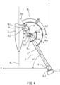
- FIG. 4 shows a perpendicular line ALv, which passes through the center point of the pair of travel wheels 9 (9L, 9R) and which is perpendicular to the fuselage guide line AL.
- an arrow F indicates a forward travel direction
- an arrow B indicates a backward travel direction.
- an angle range in which the axle angle Wr is less than the axle determination angle Wt is indicated as a smooth undocking angle range ⁇ s, within which smooth undocking can be performed.
- the current axle angle Wr is an angle within the smooth undocking angle range ⁇ (e.g., Wr1)
- the travel wheels 9 travel in a direction within a smooth undocking range ⁇ ss (e.g., the direction of an arrow As1), and the cab 6 moves away from the aircraft 3.
- the cab 6 can be smoothly undocked from the aircraft 3 by causing the travel wheels 9 to travel backward by a predetermined distance (e.g., 0.5 to 1.0 m).
- a predetermined distance e.g., 0.5 to 1.0 m.
- the rudder angle of the travel device 10 is changeable within the range of -90° to +90° with respect to the extension/retraction direction (the center line Ed) of the tunnel unit 5.
- the smooth undocking angle range ⁇ s calculated clockwise with respect to the center line Ed of the tunnel unit 5 is a range that is not less than 0° but less than the axle determination angle Wt.
- FIG. 5 is a flowchart showing one example of operations performed when undocking the passenger boarding bridge 1 from the aircraft 3 and returning the passenger boarding bridge 1 to the standby position. These operations are realized by control performed by the controller 50.
- the position coordinates of the travel device 10 (the position coordinates of the center point of the pair of travel wheels 9) at the standby position, which are indicated by XY coordinates in FIG. 1 , are prestored in the controller 50.
- the controller 50 calculates the distance from the center point of the rotunda 4 to the center point of the pair of travel wheels 9. Based on the calculated distance and a value detected by the rotunda angle sensor 24 (e.g., an angle ⁇ in the case of FIG. 1 ), the controller 50 calculates, whenever necessary, the position coordinates of the travel device 10 at the current position.
- the operator operates the control board 31 to contract the closure 63 and then, for example, pushes a return button of the control board 31 (one of the operation switches 33), the return button being configured as a dead man's switch, thereby starting automatic control for returning the passenger boarding bridge 1 to the standby position.
- the operating button for starting such automatic control need not be a dead man's switch, but may be an operating button that is operated by one-push operation.
- the automatic control may be started from, for example, an external device or a mobile terminal.
- step S1 When the aforementioned return button is pushed, an undocking command from the control board 31 is inputted to the controller 50.
- the controller 50 calculates the above-described current axle angle Wr and axle determination angle Wt, and determines whether or not the current axle angle Wr is an angle within the smooth undocking angle range ⁇ s (i.e., an angle less than the axle determination angle Wt) (step S2: undocking determination process).
- the controller 50 performs automatic travel to the standby position (step S3). Specifically, the controller 50 causes the travel wheels 9 to travel straight backward by a predetermined distance (e.g., 0.5 to 1.0 m) without changing their facing direction, then rotates the travel wheels 9 on the spot such that the direction of the backward travel of the travel wheels 9 coincides with the direction to the standby position, and thereafter causes the travel wheels 9 to travel backward to the standby position (automatic control).
- the controller 50 also controls the rotational mechanism of the cab 6 and the lifting/lowering device 8 such that, at the standby position, the facing direction of the cab 6 and the height of the tunnel unit 5 coincide with a predetermined facing direction and a predetermined height, respectively.
- the controller 50 causes the display device 34 of the control board 31 to display a warning message to prohibit (not allow) automatic travel (step S4).
- the warning message may be, for example, a message that requests for manual operation to be done carefully, such as "Abnormally docked state. Undock by manual operation with enough attention to safety.” In this case, the operator, while paying enough attention to safety, operates the travel device 10 and so forth by manual operation to undock the passenger boarding bridge 1 from the aircraft 3 and to return the passenger boarding bridge 1 to the standby position (manual control).
- the undocking determination process is performed before undocking the passenger boarding bridge 1 (the cab 6) from the aircraft 3, and the undocking method is switched (between automatic control and manual control) in accordance with the result of the determination in the undocking determination process. This makes it possible to eliminate a hindrance to the undocking from the aircraft.
- the above-described example is a case where the operator, at first, wishes to return the passenger boarding bridge 1 to the standby position by automatic control.
- a description is given of a case where the operator, from the beginning, intends to return the passenger boarding bridge 1 to the standby position by manual operation.
- the operator pushes a safety confirmation button (one of the operation switches 33) of the control board 31.
- a safety confirmation command from the control board 31 is inputted to the controller 50.
- the controller 50 performs an undocking determination process that is the same as the undocking determination process performed in step S2 of FIG. 5 .
- the controller 50 causes the display device 34 of the control board 31 to display the following message: "Normally docked state. Undock by normal operation.” Looking at the message, the operator undocks the passenger boarding bridge 1 from the aircraft 3 and returns the passenger boarding bridge 1 to the standby position by operating the travel device 10 and so forth by normal operation. Specifically, the operator causes the travel device 10 to travel backward by a predetermined distance without changing the facing direction of the travel wheels 9, thereby undocking the passenger boarding bridge 1 from the aircraft 3, and then causes the travel device 10 to travel backward to the standby position (normal operation by manual control).
- the controller 50 causes the display device 34 of the control board 31 to display the same warning message as that displayed in step S4 of FIG. 5 .
- the operator while paying enough attention to safety, operates the travel device 10 and so forth by manual operation to undock the passenger boarding bridge 1 from the aircraft 3 and to return the passenger boarding bridge 1 to the standby position (irregular operation by manual control).
- the undocking determination process is performed before undocking the passenger boarding bridge 1 (the cab 6) from the aircraft 3, and the undocking method is switched (between normal operation by manual control and irregular operation by manual control) in accordance with the result of the determination in the undocking determination process. This makes it possible to eliminate a hindrance to the undocking from the aircraft.
- the aforementioned undocking command that is inputted through an operation of the return button for starting the automatic control can be considered to include the safety confirmation command.
- messages displayed by the display device 34 may alternatively be outputted as audio messages from a speaker of, for example, the control board 31.
- second to fourth configuration examples described below may be adopted.
- the axle determination angle Wt may be calculated by adding 90 degrees to an angle Wx1 ( FIG. 1 ) formed by a tangent line TL1 (see FIG. 1 ).
- the tangent line TL1 extends horizontally and touches a surface, of the aircraft 3, with which the cab 6 is docked.
- the angle Wx1 is calculated clockwise with respect to the center line Ed of the tunnel unit 5.
- the angle Wx1 in this case may be calculated in the following manner. For example, an angle that the tangent line TL1 forms with a straight line (TL2) is calculated.
- the tangent line TL1 touches a part, of the aircraft 3, with which the cab 6 is docked (hereinafter, this part is referred to as "the cab 6-docked part" of the aircraft 3).
- the straight line (TL2) extends along a distal end edge 6a of the cab 6.
- the angle that the tangent line TL1 forms with the straight line (TL2) is calculated based on the following distances: distances detected by the two respective distance sensors 23 (see FIG. 2 and FIG.
- the angle Wx1 can be calculated. It should be noted that the rotational angle of the cab 6 is detected as an angle formed by the center line Ed of the tunnel unit 5 and a straight line that is orthogonal to the straight line (TL2) extending along the distal end edge 6a of the cab 6.
- the rotational angle of the cab 6 with respect to the center line Ed of the tunnel unit 5 is ⁇ ; the tangent line TL1, which touches the cab 6-docked part of the aircraft 3, rises more than the straight line TL2, which extends along the distal end edge 6a of the cab 6; and the angle that the tangent line TL1 forms with the straight line TL2 is Tx (Tx ⁇ 90°).
- the straight line TL2 which extends along the distal end edge 6a of the cab 6, rises more than the tangent line TL1, which touches the cab 6-docked part of the aircraft 3; and the angle that the tangent line TL1 forms with the straight line TL2 is Tx (Tx ⁇ 90°).
- the extending direction of the tangent line TL1 which touches the cab 6-docked part of the aircraft 3, is substantially the same as the extending direction of the straight line TL2, which extends along the distal end edge 6a of the cab 6 ( FIG. 1 illustrates a case where TL1 is equal to TL2).
- the axle determination angle Wt may be calculated by adding 90 degrees to an angle Wx2 (see FIG. 1 ).
- the angle Wx2 is formed by the straight line TL2, which extends along the distal end edge 6a of the cab 6 and which is calculated clockwise with respect to the center line Ed of the tunnel unit 5.
- the angle Wx2 can be calculated, for example, based on the rotational angle of the cab 6 with respect to the center line Ed of the tunnel unit 5, the rotational angle being detected by the cab angle sensor 25.
- the angle Wx2 can be calculated by an equation shown below.
- Wx 2 90 ⁇ ⁇
- the axle determination angle Wt is calculated based on the angle Wx, which is formed by the center line Ed of the tunnel unit 5 and the fuselage guide line AL drawn on the apron.
- the aircraft 3 does not necessarily come to a stop in such a manner that the aircraft axis is positioned immediately above the fuselage guide line AL. Therefore, the axle determination angle Wt may be calculated based on an angle that is formed between the center line Ed of the tunnel unit 5 and an aircraft axis line (a straight line extending along the aircraft axis) of the aircraft 3.
- the axle determination angle Wt may be calculated by adding 90 degrees to an angle (hereinafter, "angle Wx3") that is formed by the aircraft axis line of the aircraft 3 and that is calculated clockwise with respect to the center line Ed of the tunnel unit 5.
- angle Wx3 an angle that is formed by the aircraft axis line of the aircraft 3 and that is calculated clockwise with respect to the center line Ed of the tunnel unit 5.
- the controller 50 stores, for each aircraft type, an angle (hereinafter, "angle M") that is formed between the aircraft axis line of the aircraft 3 and the tangent line TL1 touching the cab 6-docked part of the aircraft 3. Then, the angle Wx3 can be calculated based on this angle M and the angle Wx1 calculated in the above-described manner.
- the above-described angle Wx2 may be used instead of the angle Wx1, because the angle Wx1 is substantially the same as the angle Wx2.
- the controller 50 may receive an actual stop position of and aircraft type information about the aircraft 3 from an external device that has a function of measuring the actual stop position of the aircraft 3, and may calculate the angle Wx3 formed by the aircraft axis line of the aircraft 3 by also using these received information.
- the external device may be, for example, VDGS (Visual Docking Guidance System).
- the controller 50 may receive an actual stop position of and aircraft type information about the aircraft 3 from an external device (e.g., VGDS) that has a function of measuring the actual stop position of the aircraft 3, and may calculate the angle Wx1 formed by the tangent line TL1, which touches the cab 6-docked part of the aircraft 3, by also using these received information.
- an external device e.g., VGDS
- the axle determination angle Wt can be calculated in a simple manner. Since the aircraft 3 does not necessarily come to a stop in such a manner that the aircraft axis is positioned immediately above the fuselage guide line AL, by adopting the fourth configuration example, a more useful axle determination angle Wt can be calculated as compared to the first configuration example. Further, in the case of adopting the second or third configuration example, a more useful axle determination angle Wt can be calculated as compared to the first and fourth configuration examples.
- the second and third configuration examples are advantageous particularly in a case where the tangent line TL1, which touches the cab 6-docked part of the aircraft 3, is not parallel to the aircraft axis line of the aircraft 3.
- the determiner 51 determines whether or not the travel direction of the backward travel of the travel wheels 9 (9L, 9R) is a direction within the smooth undocking range ⁇ ss based on whether or not the current axle angle Wr is less than the axle determination angle Wt.
- the determiner 51 may directly obtain the travel direction of the backward travel of the travel wheels 9 (9L, 9R) and the smooth undocking range ⁇ ss, and then determine whether or not the travel direction of the backward travel of the travel wheels 9 is a direction within the smooth undocking range ⁇ ss.
- the travel direction of the backward travel of the travel wheels 9 e.g., the direction of arrow B in FIG.
- the smooth undocking range ⁇ ss is a result of rotating the smooth undocking angle range ⁇ s clockwise by 90 degrees (see FIG. 4 , for example), and is a range that is not less than 90° but less than Wt + 90° as calculated clockwise with respect to the center line Ed of the tunnel unit 5.
- Wt is equal to the above-described axle determination angle Wt.
- the smooth undocking range ⁇ ss in the first configuration example is an angle range that is, in a plan view, not less than 90 degrees as calculated clockwise with respect to the center line Ed of the tunnel unit 5 before undocking the cab 6 from the aircraft 3, and is, in the plan view, less than an angle that is obtained by adding 180 degrees to the angle Wx.
- the angle Wx is formed by the fuselage guide line AL on the apron and calculated clockwise with respect to the center line Ed of the tunnel unit 5 before undocking the cab 6 from the aircraft 3.
- the smooth undocking range ⁇ ss in the second configuration example is an angle range that is, in a plan view, not less than 90 degrees as calculated clockwise with respect to the center line Ed of the tunnel unit 5 before undocking the cab 6 from the aircraft 3, and is, in the plan view, less than an angle that is obtained by adding 180 degrees to the angle Wx1.
- the angle Wx1 is formed by the tangent line TL1, which extends horizontally and touches the cab 6-docked part of the aircraft 3.
- the angle Wx1 is calculated clockwise with respect to the center line Ed of the tunnel unit 5 before undocking the cab 6 from the aircraft 3.
- the smooth undocking range ⁇ ss in the third configuration example is an angle range that is, in a plan view, not less than 90 degrees as calculated clockwise with respect to the center line Ed of the tunnel unit 5 before undocking the cab 6 from the aircraft 3, and is, in the plan view, less than an angle that is obtained by adding 180 degrees to the angle Wx2.
- the angle Wx2 is formed by the straight line TL2, which extends along the distal end edge 6a of the cab 6.
- the angle Wx2 is calculated clockwise with respect to the center line Ed of the tunnel unit 5 before undocking the cab 6 from the aircraft 3.
- the smooth undocking range ⁇ ss in the fourth configuration example is an angle range that is, in a plan view, not less than 90 degrees as calculated clockwise with respect to the center line Ed of the tunnel unit 5 before undocking the cab 6 from the aircraft 3, and is, in the plan view, less than an angle that is obtained by adding 180 degrees to the angle Wx3.
- the angle Wx3 is formed by the aircraft axis line of the aircraft 3, and is calculated clockwise with respect to the center line Ed of the tunnel unit 5 before undocking the cab 6 from the aircraft 3.
- the smooth undocking angle range ⁇ s is a range that is calculated clockwise with respect to the center line Ed of the tunnel unit 5 and that is not less than 0° but less than the axle determination angle Wt (hereinafter, this range is referred to as "range A").
- an angle range narrower than the aforementioned range A is set as the smooth undocking angle range ⁇ s used in the undocking determination process.
- a range that is excluded from the range A (hereinafter, "excluded range B") is preset for each aircraft type.
- the controller 50 prestores excluded ranges B that are set corresponding to respective aircraft types.
- the controller 50 calculates the smooth undocking angle range ⁇ s by excluding, from the range A, the excluded range B corresponding to the aircraft type of the aircraft 3.
- Each excluded range B can be set, for example, as a range less than P degrees, or a range not less than Q degrees.
- the smooth undocking angle range ⁇ s is a range that is calculated clockwise with respect to the center line Ed of the tunnel unit 5 and that is not less than P degrees but less than the axle determination angle Wt (0 ⁇ P ⁇ Wt).
- the smooth undocking angle range ⁇ s is a range that is calculated clockwise with respect to the center line Ed of the tunnel unit 5 and that is not less than 0° but less than Q degrees (0 ⁇ Q ⁇ Wt).
- the range A is the smooth undocking angle range ⁇ s.
- the controller 50 calculates the smooth undocking angle range ⁇ s based on information about an angle range that is excluded from the range A and that is preset in accordance with the aircraft type of the aircraft 3 (i.e., based on information about the excluded range B and information indicating that there is no excluded range B).
- the smooth undocking range ⁇ ss in each of the first to fourth configuration examples is an angle range (hereinafter, "range As") that is, in a plan view, not less than 90 degrees as calculated clockwise with respect to the center line Ed of the tunnel unit 5 before undocking the cab 6 from the aircraft 3, and is less than an angle that is obtained by adding 180 degrees to the above-described angle Wx, Wx1, Wx2, or Wx3 (hereinafter, "Wx0" refers to the angle Wx, Wx1, Wx2, or Wx3).
- range As an angle range
- excluded range Bs a range that is excluded from the range As (hereinafter, "excluded range Bs") is preset for each aircraft type.
- the controller 50 prestores excluded ranges Bs that are set corresponding to respective aircraft types.
- the controller 50 calculates the smooth undocking range ⁇ ss by excluding, from the range As, the excluded range Bs corresponding to the aircraft type of the aircraft 3.
- Each excluded range Bs can be set, for example, as a range less than Ps degrees, or a range not less than Qs degrees.
- the smooth undocking range ⁇ ss is a range that is calculated clockwise with respect to the center line Ed of the tunnel unit 5 and that is not less than Ps degrees but less than an angle obtained by adding 180 degrees to the angle Wx0 (90 ⁇ Ps ⁇ the angle obtained by adding 180 degrees to the angle Wx0).
- the smooth undocking range ⁇ ss is a range that is calculated clockwise with respect to the center line Ed of the tunnel unit 5 and that is not less than 90 degrees but less than Qs degrees (90 ⁇ Qs ⁇ the angle obtained by adding 180 degrees to the angle Wx0).
- the range As is the smooth undocking angle range ⁇ ss.
- the controller 50 calculates the smooth undocking range ⁇ ss based on information about an angle range that is excluded from the range As and that is preset in accordance with the aircraft type of the aircraft 3 (i.e., based on information about the excluded range Bs and information indicating that there is no excluded range Bs).
- the controller 50 may obtain the aircraft type information from an external device such as the aforementioned VDGS, or may obtain the aircraft type information about the aircraft 3 as a result of the operator pushing an aircraft type selection button provided on the control board 31.
- the present invention is useful, for example, as a passenger boarding bridge that makes it possible to eliminate a hindrance to undocking of the passenger boarding bridge from an aircraft.
Landscapes
- Engineering & Computer Science (AREA)
- Architecture (AREA)
- Civil Engineering (AREA)
- Structural Engineering (AREA)
- Mechanical Engineering (AREA)
- Aviation & Aerospace Engineering (AREA)
- Bridges Or Land Bridges (AREA)
- Control Of Position, Course, Altitude, Or Attitude Of Moving Bodies (AREA)
Claims (2)
- Fluggastbrücke (1), umfassend:eine Rotunde (4), die konfiguriert ist, um mit einem Abfertigungsgebäude (2) verbunden zu werden, und horizontal drehbar gelagert zu sein;eine Tunneleinheit (5), deren proximales Ende mit der Rotunde verbunden ist, wobei die Tunneleinheit ausziehbar und einziehbar ist, die Tunneleinheit um eine vertikale Drehachse (CL1) der Rotunde drehbar ist;eine Verfahrvorrichtung (10), welche die Tunneleinheit lagert und Verfahrräder (9) beinhaltet, die konfiguriert sind, um vorwärts und rückwärts zu verfahren, wobei die Verfahrvorrichtung konfiguriert ist, sodass eine Verfahrrichtung eines Vorwärtsverfahrens (F) der Verfahrräder und eine Verfahrrichtung des Rückwärtsverfahrens (B) der Verfahrräder änderbar sind;eine Kabine (6), die an einem distalen Ende der Tunneleinheit bereitgestellt ist, wobei die Kabine konfiguriert ist, um an ein Flugzeug (3) angedockt zu werden; undeinen Bestimmer (51), der konfiguriert ist, um zu einer Zeit vor dem Abdocken der an das Flugzeug angedockten Kabine vom Flugzeug eine Bestimmung (S2) durchzuführen, ob die Verfahrrichtung des Rückwärtsverfahrens der Verfahrräder zu dieser Zeit eine Richtung (Asl) innerhalb eines sanften Abdockbereichs (θss) ist oder nicht, wobei:
der sanfte Abdockbereich ein Winkelbereich ist, der in Draufsicht, wie im Uhrzeigersinn in Bezug auf eine Mittellinie (Ed) der Tunneleinheit vor dem Abdocken der Kabine vom Flugzeug berechnet, nicht weniger als 90 Grad beträgt, und in Draufsicht basierend auf vorbestimmten Informationen innerhalb eines Bereichs von weniger als einem Winkel (Wx0) eingestellt wird, der durch Addieren von 180 Grad zu einem der folgenden Winkel erhalten wird:einem Winkel (Wx1), der durch eine Tangentenlinie (TL1) gebildet wird und im Uhrzeigersinn in Bezug auf die Mittellinie (Ed) der Tunneleinheit vor dem Abdocken der Kabine vom Flugzeug berechnet wird, wobei sich die Tangentenlinie (TL1) horizontal erstreckt und einen Kabinen-Andock-Teil des Flugzeugs berührt;einem Winkel (Wx2), der durch eine gerade Linie (TL2) gebildet wird und der im Uhrzeigersinn in Bezug auf die Mittellinie (Ed) der Tunneleinheit vor dem Abdocken der Kabine vom Flugzeug berechnet wird, wobei sich die gerade Linie (TL2) entlang einer distalen Endkante (6a) der Kabine erstreckt;einem Winkel (Wx), der durch eine auf eine Schürze gezogene Rumpfführungslinie (AL) gebildet wird und der im Uhrzeigersinn in Bezug auf die Mittellinie (Ed) der Tunneleinheit vor dem Abdocken der Kabine vom Flugzeug berechnet wird; undeinem Winkel (Wx3), der durch eine Flugzeugachsenlinie des Flugzeugs gebildet wird und der im Uhrzeigersinn in Bezug auf die Mittellinie der Tunneleinheit vor dem Abdocken der Kabine vom Flugzeug berechnet wird. - Fluggastbrücke nach Anspruch 1, wobeider Bestimmer konfiguriert ist, um die Bestimmung durchzuführen, wenn ein Abdockbefehl eingegeben wird,die Verfahrvorrichtung konfiguriert ist, um:in einem Fall, in dem ein Ergebnis der Bestimmung (S2), die von dem Bestimmer durchgeführt wird, angibt, dass die Verfahrrichtung des Rückwärtsverfahrens der Verfahrräder eine Richtung innerhalb des sanften Abdockbereichs ist, ein automatisches Verfahren (S3) durchzuführen, bei dem die Verfahrvorrichtung um einen vorbestimmten Abstand rückwärts verfährt, ohne eine Blickrichtung der Verfahrräder zu ändern, und dann rückwärts zu einer vorbestimmten Standby-Position verfährt; undin einem Fall, in dem das Ergebnis der Bestimmung, die von dem Bestimmer durchgeführt wird, angibt, dass die Verfahrrichtung des Rückwärtsverfahrens der Verfahrräder keine Richtung innerhalb des sanften Abdockbereichs ist, Nichtdurchführen des automatischen Verfahrens, unddie Fluggastbrücke weiter eine Warneinheit umfasst, die konfiguriert ist, um eine Warnung (S4) in dem Fall durchzuführen, in dem das Ergebnis der Bestimmung, die von dem Bestimmer durchgeführt wird, angibt, dass die Verfahrrichtung des Rückwärtsverfahrens der Verfahrräder keine Richtung innerhalb des sanften Abdockbereichs ist.
Applications Claiming Priority (1)
| Application Number | Priority Date | Filing Date | Title |
|---|---|---|---|
| PCT/JP2019/042579 WO2021084650A1 (ja) | 2019-10-30 | 2019-10-30 | 旅客搭乗橋 |
Publications (3)
| Publication Number | Publication Date |
|---|---|
| EP4053022A1 EP4053022A1 (de) | 2022-09-07 |
| EP4053022A4 EP4053022A4 (de) | 2023-07-05 |
| EP4053022B1 true EP4053022B1 (de) | 2025-04-30 |
Family
ID=72745132
Family Applications (1)
| Application Number | Title | Priority Date | Filing Date |
|---|---|---|---|
| EP19950887.0A Active EP4053022B1 (de) | 2019-10-30 | 2019-10-30 | Fluggastbrücke |
Country Status (4)
| Country | Link |
|---|---|
| US (1) | US12583622B2 (de) |
| EP (1) | EP4053022B1 (de) |
| JP (1) | JP6770665B1 (de) |
| WO (1) | WO2021084650A1 (de) |
Families Citing this family (2)
| Publication number | Priority date | Publication date | Assignee | Title |
|---|---|---|---|---|
| WO2022208601A1 (ja) * | 2021-03-29 | 2022-10-06 | 新明和工業株式会社 | 旅客搭乗橋 |
| CN114509822B (zh) * | 2022-01-20 | 2023-04-07 | 中铁二院工程集团有限责任公司 | 铁路隧道的地空电磁法阵列勘察方法及其测线布置方法 |
Family Cites Families (18)
| Publication number | Priority date | Publication date | Assignee | Title |
|---|---|---|---|---|
| US5855035A (en) * | 1996-12-30 | 1999-01-05 | Thyssen Stearns, Inc. | Method and apparatus for reducing skidding of wheels on a passenger boarding bridge |
| JP2003212194A (ja) * | 2002-01-24 | 2003-07-30 | Mitsubishi Heavy Ind Ltd | ボーディングブリッジの自動制御装置および自動制御システムおよびその位置合わせ方法 |
| US20030145405A1 (en) * | 2002-02-01 | 2003-08-07 | Neil Hutton | Method and apparatus for automatically pre-positioning a passenger bridge |
| US7093314B2 (en) * | 2002-05-07 | 2006-08-22 | Dew Engineering And Development Limited | Beacon docking system with visual guidance display |
| JP2004082833A (ja) * | 2002-08-26 | 2004-03-18 | Zennikku Motor Service Kk | ボーディングブリッジ |
| JP2004314700A (ja) * | 2003-04-14 | 2004-11-11 | Zennikku Motor Service Kk | ボーディングブリッジ自動走行装置および自動走行方法 |
| JP4293874B2 (ja) * | 2003-09-29 | 2009-07-08 | 新明和工業株式会社 | ボーディングブリッジ及びボーディングブリッジの目標位置の設定方法 |
| CN1332854C (zh) * | 2004-02-26 | 2007-08-22 | 中国国际海运集装箱(集团)股份有限公司 | 登机桥辅助支撑装置和带有该装置的登机桥及其控制方法 |
| US7603736B2 (en) * | 2006-03-20 | 2009-10-20 | Dew Engineering And Development Ulc | Method for aligning a plurality of passenger boarding bridges |
| JP5111075B2 (ja) * | 2007-11-30 | 2012-12-26 | 全日空モーターサービス株式会社 | ボーディングブリッジ、ボーディングブリッジシステム、およびボーディングブリッジの装着方法 |
| ES2357223B1 (es) * | 2008-05-28 | 2012-01-02 | Thyssenkrupp Elevator Innovation Center, S.A. | Sistema anticolision entre pasarelas de acceso a aeronaves. |
| GB2531231B (en) * | 2013-07-13 | 2020-03-04 | Borealis Tech Ltd | Improved aircraft gate parking and servicing method |
| JP5813892B1 (ja) * | 2015-03-16 | 2015-11-17 | 株式会社Naaエレテック | 搭乗橋格納姿勢修正システム |
| JP6744789B2 (ja) | 2016-09-06 | 2020-08-19 | 新明和工業株式会社 | 旅客搭乗橋 |
| JP6728098B2 (ja) * | 2017-04-28 | 2020-07-22 | 三菱重工交通機器エンジニアリング株式会社 | ボーディングブリッジ |
| US10519614B2 (en) * | 2017-06-26 | 2019-12-31 | Teh Boeing Company | System and method for automated deployment of a passenger boarding bridge |
| WO2019012648A1 (ja) * | 2017-07-13 | 2019-01-17 | 新明和工業株式会社 | 旅客搭乗橋 |
| CA3107208A1 (en) * | 2018-06-27 | 2020-01-02 | thyssenkrupp Airport Solutions, S.A. | Method of automated undocking a passenger boarding bridge from an aircraft |
-
2019
- 2019-10-30 EP EP19950887.0A patent/EP4053022B1/de active Active
- 2019-10-30 JP JP2020542167A patent/JP6770665B1/ja active Active
- 2019-10-30 US US17/764,949 patent/US12583622B2/en active Active
- 2019-10-30 WO PCT/JP2019/042579 patent/WO2021084650A1/ja not_active Ceased
Also Published As
| Publication number | Publication date |
|---|---|
| JPWO2021084650A1 (ja) | 2021-11-18 |
| WO2021084650A1 (ja) | 2021-05-06 |
| US12583622B2 (en) | 2026-03-24 |
| US20220289402A1 (en) | 2022-09-15 |
| EP4053022A1 (de) | 2022-09-07 |
| JP6770665B1 (ja) | 2020-10-14 |
| EP4053022A4 (de) | 2023-07-05 |
Similar Documents
| Publication | Publication Date | Title |
|---|---|---|
| US10875666B2 (en) | Passenger boarding bridge | |
| US12275539B2 (en) | Method of controlling traveling of passenger boarding bridge | |
| EP4053022B1 (de) | Fluggastbrücke | |
| EP4071576B1 (de) | Bewegungssperre für plattformbewegungssystem | |
| US20200018079A1 (en) | Work Platform Mover System | |
| JP6744789B2 (ja) | 旅客搭乗橋 | |
| US12404037B2 (en) | Passenger boarding bridge | |
| US12269613B2 (en) | System for performing automatic inspection of passenger boarding bridge | |
| US20230202683A1 (en) | Passenger boarding bridge | |
| US20240101275A1 (en) | Passenger boarding bridge | |
| JP7213212B2 (ja) | 旅客搭乗橋 | |
| WO2022190667A1 (ja) | 旅客搭乗橋 | |
| US20240391607A1 (en) | Passenger boarding bridge | |
| JP2004314700A (ja) | ボーディングブリッジ自動走行装置および自動走行方法 |
Legal Events
| Date | Code | Title | Description |
|---|---|---|---|
| STAA | Information on the status of an ep patent application or granted ep patent |
Free format text: STATUS: THE INTERNATIONAL PUBLICATION HAS BEEN MADE |
|
| PUAI | Public reference made under article 153(3) epc to a published international application that has entered the european phase |
Free format text: ORIGINAL CODE: 0009012 |
|
| STAA | Information on the status of an ep patent application or granted ep patent |
Free format text: STATUS: REQUEST FOR EXAMINATION WAS MADE |
|
| 17P | Request for examination filed |
Effective date: 20220331 |
|
| AK | Designated contracting states |
Kind code of ref document: A1 Designated state(s): AL AT BE BG CH CY CZ DE DK EE ES FI FR GB GR HR HU IE IS IT LI LT LU LV MC MK MT NL NO PL PT RO RS SE SI SK SM TR |
|
| DAV | Request for validation of the european patent (deleted) | ||
| DAX | Request for extension of the european patent (deleted) | ||
| A4 | Supplementary search report drawn up and despatched |
Effective date: 20230602 |
|
| RIC1 | Information provided on ipc code assigned before grant |
Ipc: B64F 1/305 20060101AFI20230526BHEP |
|
| GRAP | Despatch of communication of intention to grant a patent |
Free format text: ORIGINAL CODE: EPIDOSNIGR1 |
|
| STAA | Information on the status of an ep patent application or granted ep patent |
Free format text: STATUS: GRANT OF PATENT IS INTENDED |
|
| INTG | Intention to grant announced |
Effective date: 20241129 |
|
| GRAS | Grant fee paid |
Free format text: ORIGINAL CODE: EPIDOSNIGR3 |
|
| GRAA | (expected) grant |
Free format text: ORIGINAL CODE: 0009210 |
|
| STAA | Information on the status of an ep patent application or granted ep patent |
Free format text: STATUS: THE PATENT HAS BEEN GRANTED |
|
| AK | Designated contracting states |
Kind code of ref document: B1 Designated state(s): AL AT BE BG CH CY CZ DE DK EE ES FI FR GB GR HR HU IE IS IT LI LT LU LV MC MK MT NL NO PL PT RO RS SE SI SK SM TR |
|
| P01 | Opt-out of the competence of the unified patent court (upc) registered |
Free format text: CASE NUMBER: APP_13866/2025 Effective date: 20250320 |
|
| REG | Reference to a national code |
Ref country code: CH Ref legal event code: EP Ref country code: GB Ref legal event code: FG4D |
|
| REG | Reference to a national code |
Ref country code: DE Ref legal event code: R096 Ref document number: 602019069505 Country of ref document: DE |
|
| REG | Reference to a national code |
Ref country code: IE Ref legal event code: FG4D |
|
| REG | Reference to a national code |
Ref country code: NL Ref legal event code: MP Effective date: 20250430 |
|
| REG | Reference to a national code |
Ref country code: AT Ref legal event code: MK05 Ref document number: 1789862 Country of ref document: AT Kind code of ref document: T Effective date: 20250430 |
|
| PG25 | Lapsed in a contracting state [announced via postgrant information from national office to epo] |
Ref country code: FI Free format text: LAPSE BECAUSE OF FAILURE TO SUBMIT A TRANSLATION OF THE DESCRIPTION OR TO PAY THE FEE WITHIN THE PRESCRIBED TIME-LIMIT Effective date: 20250430 Ref country code: PT Free format text: LAPSE BECAUSE OF FAILURE TO SUBMIT A TRANSLATION OF THE DESCRIPTION OR TO PAY THE FEE WITHIN THE PRESCRIBED TIME-LIMIT Effective date: 20250901 Ref country code: ES Free format text: LAPSE BECAUSE OF FAILURE TO SUBMIT A TRANSLATION OF THE DESCRIPTION OR TO PAY THE FEE WITHIN THE PRESCRIBED TIME-LIMIT Effective date: 20250430 |
|
| REG | Reference to a national code |
Ref country code: LT Ref legal event code: MG9D |
|
| PG25 | Lapsed in a contracting state [announced via postgrant information from national office to epo] |
Ref country code: GR Free format text: LAPSE BECAUSE OF FAILURE TO SUBMIT A TRANSLATION OF THE DESCRIPTION OR TO PAY THE FEE WITHIN THE PRESCRIBED TIME-LIMIT Effective date: 20250731 Ref country code: NO Free format text: LAPSE BECAUSE OF FAILURE TO SUBMIT A TRANSLATION OF THE DESCRIPTION OR TO PAY THE FEE WITHIN THE PRESCRIBED TIME-LIMIT Effective date: 20250730 |
|
| PG25 | Lapsed in a contracting state [announced via postgrant information from national office to epo] |
Ref country code: NL Free format text: LAPSE BECAUSE OF FAILURE TO SUBMIT A TRANSLATION OF THE DESCRIPTION OR TO PAY THE FEE WITHIN THE PRESCRIBED TIME-LIMIT Effective date: 20250430 Ref country code: PL Free format text: LAPSE BECAUSE OF FAILURE TO SUBMIT A TRANSLATION OF THE DESCRIPTION OR TO PAY THE FEE WITHIN THE PRESCRIBED TIME-LIMIT Effective date: 20250430 |
|
| PG25 | Lapsed in a contracting state [announced via postgrant information from national office to epo] |
Ref country code: BG Free format text: LAPSE BECAUSE OF FAILURE TO SUBMIT A TRANSLATION OF THE DESCRIPTION OR TO PAY THE FEE WITHIN THE PRESCRIBED TIME-LIMIT Effective date: 20250430 |
|
| PG25 | Lapsed in a contracting state [announced via postgrant information from national office to epo] |
Ref country code: HR Free format text: LAPSE BECAUSE OF FAILURE TO SUBMIT A TRANSLATION OF THE DESCRIPTION OR TO PAY THE FEE WITHIN THE PRESCRIBED TIME-LIMIT Effective date: 20250430 |
|
| PG25 | Lapsed in a contracting state [announced via postgrant information from national office to epo] |
Ref country code: AT Free format text: LAPSE BECAUSE OF FAILURE TO SUBMIT A TRANSLATION OF THE DESCRIPTION OR TO PAY THE FEE WITHIN THE PRESCRIBED TIME-LIMIT Effective date: 20250430 |
|
| PG25 | Lapsed in a contracting state [announced via postgrant information from national office to epo] |
Ref country code: RS Free format text: LAPSE BECAUSE OF FAILURE TO SUBMIT A TRANSLATION OF THE DESCRIPTION OR TO PAY THE FEE WITHIN THE PRESCRIBED TIME-LIMIT Effective date: 20250731 |
|
| PG25 | Lapsed in a contracting state [announced via postgrant information from national office to epo] |
Ref country code: IS Free format text: LAPSE BECAUSE OF FAILURE TO SUBMIT A TRANSLATION OF THE DESCRIPTION OR TO PAY THE FEE WITHIN THE PRESCRIBED TIME-LIMIT Effective date: 20250830 |
|
| PG25 | Lapsed in a contracting state [announced via postgrant information from national office to epo] |
Ref country code: LV Free format text: LAPSE BECAUSE OF FAILURE TO SUBMIT A TRANSLATION OF THE DESCRIPTION OR TO PAY THE FEE WITHIN THE PRESCRIBED TIME-LIMIT Effective date: 20250430 |
|
| PGFP | Annual fee paid to national office [announced via postgrant information from national office to epo] |
Ref country code: DE Payment date: 20251020 Year of fee payment: 7 |
|
| PGFP | Annual fee paid to national office [announced via postgrant information from national office to epo] |
Ref country code: GB Payment date: 20251017 Year of fee payment: 7 |
|
| PG25 | Lapsed in a contracting state [announced via postgrant information from national office to epo] |
Ref country code: DK Free format text: LAPSE BECAUSE OF FAILURE TO SUBMIT A TRANSLATION OF THE DESCRIPTION OR TO PAY THE FEE WITHIN THE PRESCRIBED TIME-LIMIT Effective date: 20250430 Ref country code: SM Free format text: LAPSE BECAUSE OF FAILURE TO SUBMIT A TRANSLATION OF THE DESCRIPTION OR TO PAY THE FEE WITHIN THE PRESCRIBED TIME-LIMIT Effective date: 20250430 |
|
| PGFP | Annual fee paid to national office [announced via postgrant information from national office to epo] |
Ref country code: FR Payment date: 20251017 Year of fee payment: 7 |
|
| PG25 | Lapsed in a contracting state [announced via postgrant information from national office to epo] |
Ref country code: CZ Free format text: LAPSE BECAUSE OF FAILURE TO SUBMIT A TRANSLATION OF THE DESCRIPTION OR TO PAY THE FEE WITHIN THE PRESCRIBED TIME-LIMIT Effective date: 20250430 |
|
| PG25 | Lapsed in a contracting state [announced via postgrant information from national office to epo] |
Ref country code: EE Free format text: LAPSE BECAUSE OF FAILURE TO SUBMIT A TRANSLATION OF THE DESCRIPTION OR TO PAY THE FEE WITHIN THE PRESCRIBED TIME-LIMIT Effective date: 20250430 |
|
| PG25 | Lapsed in a contracting state [announced via postgrant information from national office to epo] |
Ref country code: SK Free format text: LAPSE BECAUSE OF FAILURE TO SUBMIT A TRANSLATION OF THE DESCRIPTION OR TO PAY THE FEE WITHIN THE PRESCRIBED TIME-LIMIT Effective date: 20250430 |
|
| PG25 | Lapsed in a contracting state [announced via postgrant information from national office to epo] |
Ref country code: IT Free format text: LAPSE BECAUSE OF FAILURE TO SUBMIT A TRANSLATION OF THE DESCRIPTION OR TO PAY THE FEE WITHIN THE PRESCRIBED TIME-LIMIT Effective date: 20250430 |
|
| REG | Reference to a national code |
Ref country code: DE Ref legal event code: R097 Ref document number: 602019069505 Country of ref document: DE |
|
| PG25 | Lapsed in a contracting state [announced via postgrant information from national office to epo] |
Ref country code: RO Free format text: LAPSE BECAUSE OF FAILURE TO SUBMIT A TRANSLATION OF THE DESCRIPTION OR TO PAY THE FEE WITHIN THE PRESCRIBED TIME-LIMIT Effective date: 20250430 |
|
| PLBE | No opposition filed within time limit |
Free format text: ORIGINAL CODE: 0009261 |
|
| STAA | Information on the status of an ep patent application or granted ep patent |
Free format text: STATUS: NO OPPOSITION FILED WITHIN TIME LIMIT |
|
| REG | Reference to a national code |
Ref country code: CH Ref legal event code: L10 Free format text: ST27 STATUS EVENT CODE: U-0-0-L10-L00 (AS PROVIDED BY THE NATIONAL OFFICE) Effective date: 20260311 |