EP4050224B1 - Coupling device - Google Patents
Coupling device Download PDFInfo
- Publication number
- EP4050224B1 EP4050224B1 EP20879718.3A EP20879718A EP4050224B1 EP 4050224 B1 EP4050224 B1 EP 4050224B1 EP 20879718 A EP20879718 A EP 20879718A EP 4050224 B1 EP4050224 B1 EP 4050224B1
- Authority
- EP
- European Patent Office
- Prior art keywords
- support member
- hole
- support
- connecting rod
- connecting device
- Prior art date
- Legal status (The legal status is an assumption and is not a legal conclusion. Google has not performed a legal analysis and makes no representation as to the accuracy of the status listed.)
- Active
Links
Images


Classifications
-
- B—PERFORMING OPERATIONS; TRANSPORTING
- B23—MACHINE TOOLS; METAL-WORKING NOT OTHERWISE PROVIDED FOR
- B23P—METAL-WORKING NOT OTHERWISE PROVIDED FOR; COMBINED OPERATIONS; UNIVERSAL MACHINE TOOLS
- B23P19/00—Machines for simply fitting together or separating metal parts or objects, or metal and non-metal parts, whether or not involving some deformation; Tools or devices therefor so far as not provided for in other classes
- B23P19/04—Machines for simply fitting together or separating metal parts or objects, or metal and non-metal parts, whether or not involving some deformation; Tools or devices therefor so far as not provided for in other classes for assembling or disassembling parts
-
- F—MECHANICAL ENGINEERING; LIGHTING; HEATING; WEAPONS; BLASTING
- F16—ENGINEERING ELEMENTS AND UNITS; GENERAL MEASURES FOR PRODUCING AND MAINTAINING EFFECTIVE FUNCTIONING OF MACHINES OR INSTALLATIONS; THERMAL INSULATION IN GENERAL
- F16B—DEVICES FOR FASTENING OR SECURING CONSTRUCTIONAL ELEMENTS OR MACHINE PARTS TOGETHER, e.g. NAILS, BOLTS, CIRCLIPS, CLAMPS, CLIPS OR WEDGES; JOINTS OR JOINTING
- F16B21/00—Means for preventing relative axial movement of a pin, spigot, shaft or the like and a member surrounding it; Stud-and-socket releasable fastenings
- F16B21/10—Means for preventing relative axial movement of a pin, spigot, shaft or the like and a member surrounding it; Stud-and-socket releasable fastenings by separate parts
- F16B21/16—Means for preventing relative axial movement of a pin, spigot, shaft or the like and a member surrounding it; Stud-and-socket releasable fastenings by separate parts with grooves or notches in the pin or shaft
- F16B21/165—Means for preventing relative axial movement of a pin, spigot, shaft or the like and a member surrounding it; Stud-and-socket releasable fastenings by separate parts with grooves or notches in the pin or shaft with balls or rollers
-
- F—MECHANICAL ENGINEERING; LIGHTING; HEATING; WEAPONS; BLASTING
- F16—ENGINEERING ELEMENTS AND UNITS; GENERAL MEASURES FOR PRODUCING AND MAINTAINING EFFECTIVE FUNCTIONING OF MACHINES OR INSTALLATIONS; THERMAL INSULATION IN GENERAL
- F16B—DEVICES FOR FASTENING OR SECURING CONSTRUCTIONAL ELEMENTS OR MACHINE PARTS TOGETHER, e.g. NAILS, BOLTS, CIRCLIPS, CLAMPS, CLIPS OR WEDGES; JOINTS OR JOINTING
- F16B2/00—Friction-grip releasable fastenings
- F16B2/02—Clamps, i.e. with gripping action effected by positive means other than the inherent resistance to deformation of the material of the fastening
- F16B2/16—Clamps, i.e. with gripping action effected by positive means other than the inherent resistance to deformation of the material of the fastening using rollers or balls
-
- B—PERFORMING OPERATIONS; TRANSPORTING
- B23—MACHINE TOOLS; METAL-WORKING NOT OTHERWISE PROVIDED FOR
- B23Q—DETAILS, COMPONENTS, OR ACCESSORIES FOR MACHINE TOOLS, e.g. ARRANGEMENTS FOR COPYING OR CONTROLLING; MACHINE TOOLS IN GENERAL CHARACTERISED BY THE CONSTRUCTION OF PARTICULAR DETAILS OR COMPONENTS; COMBINATIONS OR ASSOCIATIONS OF METAL-WORKING MACHINES, NOT DIRECTED TO A PARTICULAR RESULT
- B23Q1/00—Members which are comprised in the general build-up of a form of machine, particularly relatively large fixed members
- B23Q1/0063—Connecting non-slidable parts of machine tools to each other
- B23Q1/0072—Connecting non-slidable parts of machine tools to each other using a clamping opening for receiving an insertion bolt or nipple
-
- B—PERFORMING OPERATIONS; TRANSPORTING
- B23—MACHINE TOOLS; METAL-WORKING NOT OTHERWISE PROVIDED FOR
- B23Q—DETAILS, COMPONENTS, OR ACCESSORIES FOR MACHINE TOOLS, e.g. ARRANGEMENTS FOR COPYING OR CONTROLLING; MACHINE TOOLS IN GENERAL CHARACTERISED BY THE CONSTRUCTION OF PARTICULAR DETAILS OR COMPONENTS; COMBINATIONS OR ASSOCIATIONS OF METAL-WORKING MACHINES, NOT DIRECTED TO A PARTICULAR RESULT
- B23Q3/00—Devices holding, supporting, or positioning work or tools, of a kind normally removable from the machine
Definitions
- the present invention relates to a device configured to detachably connect a second block to a first block.
- Patent Literature 1 Japanese Unexamined Patent Publication No. 2014-092180 .
- the known device is structured as follows.
- the known connecting device is configured to detachably connect a connecting rod, protruding downward from an under surface of an object to be connected, to a housing of the connecting device.
- a tubular guide sleeve is inserted in a cylinder hole of the housing so that the movement of the guide sleeve is allowed in a left-right direction but is restricted in an up-down direction (axial direction).
- a plurality of engagement balls are inserted through a tubular wall of the guide sleeve so as to be movable in a radial direction of a tubular hole of the guide sleeve.
- the tubular hole of the guide sleeve is communicatively connected to a guide hole provided through an upper wall of the housing.
- a tubular switch sleeve is fitted over the guide sleeve so as to be movable in the above radial direction.
- the switch sleeve is provided with, on its inner peripheral wall, a wedge surface configured to push the engagement balls inward in the radial direction.
- a piston configured to move the switch sleeve in the up-down direction is hermetically inserted between an outer peripheral surface of the switch sleeve and the cylinder hole of the housing so as to be movable in the up-down direction.
- Patent Literature 1 Japanese Unexamined Patent Publication No. 2014-092180
- the above-described known connecting device is advantageous in that, even if the axis of the connecting rod is misaligned with the axis of the guide hole, the misalignment can be fixed by moving the guide sleeve and the switch sleeve in the radial direction relative to the piston. It is not expected, however, to use such a connecting device in situations in which a stress due to the self-weight of an object to be connected including the connecting rod, that is, a heavy load is applied to the connecting device via the connecting rod. Such a situation can occur, for example, when the connecting device is rotated into a horizontal orientation, in which the axis of the device is not in parallel to a vertical direction, and attached to a side wall of a first block.
- the connecting rod to which the load of an object to be connected is applied, strongly pushes or rotates the guide sleeve and/or the engagement balls in one direction in the tubular hole of the switch sleeve. This may create gaps between some of the engagement balls and the engaged portion of the rod, and the load is therefore applied only to the other engagement balls. This decreases the force transmitted from the piston to the connecting rod via the engagement balls.
- An object of the present invention is to provide a connecting device capable of firmly connecting an object, even if an external force is applied to the device in a direction crossing its axis.
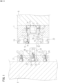
- a connecting device configured to detachably connect a first block R and a second block P to each other is structured as follows, for example as shown in FIG. 1 to FIG. 5 .
- a cylinder hole 2 is provided in a housing 1 to be attached to the first block R.
- An output member 5 is inserted in the cylinder hole 2 so as to be movable in an axial direction of the cylinder hole 2.
- a plurality of engagement members 16, 38 which are movable in a radial direction of the cylinder hole 2, are supported by the housing 1 or by the output member 5. The engagement members 16, 38 are moved inward in the radial direction by movement of the output member 5 in the axial direction.
- An insertion hole 18 opens onto a leading end surface of the housing 1.
- At least one support hole 19, 20 is provided in the housing 1 so as to extend in parallel to an axial direction of the insertion hole 18.
- a connecting rod 22 provided so as to protrude from a base plate 21 to be attached to a side wall surface of the second block P is configured to be movable on a surface 21a of the base plate 21.
- the connecting rod 22 is configured to be insertable into the insertion hole 18.
- An engaged portion 34 configured to be contactable with the engagement members 16, 38 is provided on an outer peripheral wall of the connecting rod 22 in its circumferential direction.
- At least one support member 23, 24 is provided so as to protrude from the base plate 21 in parallel to an axial direction of the connecting rod 22.
- the support member 23, 24 is configured to be inserted in the support hole 19, 20.
- the support member is provided so as to protrude from the base plate of the connecting device, while the connecting rod is provided so as to protrude and to be movable on the surface of the base plate. Due to this, when the connecting device is used in the horizontal orientation, a vertically downward load due to the self-weight of the second block or the like is received by the support member, and is not applied to the connecting rod because the connecting rod is movable on the surface of the base plate. As a result, the driving force of the output member is reliably transmitted to the connecting rod via the balls, even if an external force is applied to the second block.
- a portion of the output member 5 has a tubular shape, and guide holes 37 are bored through a tubular wall of the output member 5 in the radial direction of the cylinder hole 2.
- the engagement members 38 are respectively inserted in the guide holes 37 so as to be movable in the radial direction.
- a wedge portion 39 configured to be contactable with the engagement members 38 is provided on an inner peripheral wall of the cylinder hole 2.
- This arrangement makes it possible to reliably transmit the driving force of the output member to the connecting rod via the balls.
- the at least one support member 23, 24 includes a first support member 23 and a second support member 24, which are provided so as to protrude from the base plate 21 with the connecting rod 22 interposed between the first and second support members 23 and 24.
- the at least one support hole 19, 20 includes a first support hole 19 with a circular hole shape, into which the first support member 23 is to be inserted, and a second support hole 20 with a circular hole shape, into which the second support member 24 is to be inserted.
- the first support member 23 has a cylindrical outer peripheral wall; and the second support member 24 has projecting portions 24a respectively provided on both sides of a cylindrical outer peripheral wall of the second support member 24 in a direction crossing a direction connecting the first support member 23 to the second support member 24.
- This arrangement allows the second support member to move within the second support hole in the direction connecting the first support member to the second support member, even if there is a difference between (i) the distance between the first support hole and the second support hole and (ii) the distance between the first support member and the second support member. Furthermore, when the connecting device is used in the horizontal orientation, the vertical load acting on the second block is received by the first block via the projecting portions and via the second support hole.
- the at least one support member 23, 24 includes a first support member 23 and a second support member 24, which are provided so as to protrude from the base plate 21 with the connecting rod 22 interposed between the first and second support members 23 and 24.
- the at least one support hole 19, 20 includes a first support hole 19 with a circular hole shape, into which the first support member 23 is to be inserted, and a second support hole 20 with a circular hole shape, into which the second support member 24 is to be inserted.
- the first support member 23 has a cylindrical outer peripheral wall.
- the second support member 24 has an oval prism shape, a longitudinal axis of an oval of the oval prism shape extending in a direction crossing a direction connecting the first support member 23 to the second support member 24.
- This arrangement allows the second support member to move within the second support hole in the direction connecting the first support member to the second support member, even if there is a difference between (i) the distance between the first support hole and the second support hole and (ii) the distance between the first support member and the second support member. Furthermore, when the connecting device is used in the horizontal orientation, the vertical load acting on the second block is received by the first block via the second support member of the oval prism shape and via the second support hole.
- the at least one support member 23, 24 includes a first support member 23 and a second support member 24, which are provided so as to protrude from the base plate 21 with the connecting rod 22 interposed between the first and second support members 23 and 24.
- the at least one support hole 19, 20 includes a first support hole 19 with a circular hole shape, into which the first support member 23 is to be inserted, and a second support hole 20 with an elongated hole shape, into which the second support member 24 is to be inserted, a longitudinal axis of the elongated hole shape extending in a direction connecting the first support hole 19 to the second support hole 20.
- Each of the first support member 23 and the second support member 24 has a cylindrical outer peripheral wall.
- This arrangement allows the second support member to move within the second support hole in the direction connecting the first support hole to the second support hole, even if there is a difference between (i) the distance between the first support hole and the second support hole and (ii) the distance between the first support member and the second support member. Furthermore, when the connecting device is used in the horizontal orientation, the vertical load acting on the second block is received by the first block via the second support member and via the oval second support hole.
- a connecting device capable of firmly connecting an object, even if an external force is applied to the device in a direction crossing the axis of the device.
- FIG. 1 to FIG. 3 show a first embodiment of the present invention.
- This embodiment deals with, by way of example, a connecting device to be attached to a leading end portion of a robot arm R of an articulated robot.
- the connecting device is configured to detachably connect a pallet P to the leading end portion of the robot arm R.
- FIG. 1 the structure of the connecting device will be described with reference to FIG. 1 . It should be noted that the left and right in the following description respectively refer to the left and right in the drawings.
- a housing 1 of the connecting device is attached, in a left-right direction, to the left end portion (leading end portion) of the robot arm R (first block).
- the housing 1 has a cylinder hole 2 bored in the left-right direction.
- the cylinder hole 2 has a large-diameter hole 3 and a small-diameter hole 4, which are arranged in this order from the right to the left.
- a piston portion 6 of an output member 5 is hermetically inserted in the large-diameter hole 3 so as to be movable in the left-right direction.
- An operation portion 7 of the output member 5 is hermetically inserted in the small-diameter hole 4.
- a lock chamber 8 is provided to the right of the output member 5, and a release chamber 9 is provided between the large-diameter hole 3 and the operation portion 7.
- a supply and discharge passage 10 through which compressed air is supplied to and discharged from the lock chamber 8 is provided in the housing 1. Furthermore, a supply and discharge passage 11 through which compressed air is supplied to and discharged from the release chamber 9 is provided in the housing 1.
- An attachment hole 12 is provided in a right portion of the output member 5, and a holding spring 13 is attached in the attachment hole 12. The holding spring 13 biases the output member 5 leftward relative to a right wall (base end wall) 1a of the housing 1.
- the above-described connecting device is provided with a tubular support member 14 protruding rightward from a left wall (leading end wall) 1b of the housing 1 into the cylinder hole 2.
- Three guide holes 15 are bored through a tubular wall of the support member 14 in its radial direction.
- FIG. 1 to FIG. 3 each shows one of the three guide holes 15.
- a ball (engagement member) 16 is inserted in each of the guide holes 15 so as to be movable in the radial direction.
- An inner peripheral surface of the operation portion 7 of the output member 5 is arranged so that the distance in the radial direction between the surface and an axis of the cylinder hole 2 increases toward the left in the axial direction.
- the balls 16 are contactable with a wedge surface (wedge portion) 17 provided on the inner peripheral wall.
- the insertion hole 18 is communicatively connected to the cylinder hole 2 through the tubular hole of the support member 14.
- support holes 19 and 20 are bored so as to extend in parallel to the axial direction of the insertion hole 18.
- the support holes 19 and 20 are disposed at predetermined intervals with the insertion hole 18 interposed therebetween.
- a connecting rod 22 and two pins (support members) 23 and 24 are provided so as to protrude rightward (in a horizontal direction) from a base plate 21 and so as to be in parallel to one another.
- the base plate 21 is to be attached to a right wall surface of the pallet (second block) P.
- a through hole is bored through the base plate 21 in the left-right direction and the connecting rod 22 is inserted in the through hole.
- the through hole has a large-diameter hole 26 and a small-diameter hole 27, which are arranged in this order from the left to the right.
- the small-diameter hole 27 has a diameter smaller than that of the large-diameter hole 26.
- the connecting rod 22 has a base end portion 28 and a leading end portion 29, which are arranged in this order from the left to the right.
- the base end portion 28 has: a large-diameter portion 30 inserted in the large-diameter hole 26 of the through hole; and a small-diameter portion 31 inserted in the small-diameter hole 27 of the through hole.
- the diameter of the large-diameter hole 26 is designed to be larger than the diameter of the large-diameter portion 30.
- the diameter of the small-diameter hole 27 is designed to be larger than that of the small-diameter portion 31.
- the diameter of the small-diameter hole 27 is designed to be smaller than that of the large-diameter portion 30.
- the depth of the small-diameter hole 27 is slightly longer than the size of the small-diameter portion 31 in the left-right direction. The difference is as small as a clearance for fitting. Due to this, a peripheral wall of the small-diameter hole 27 is sandwiched by a left end surface of the leading end portion 29 and a right end surface of the large-diameter portion 30.
- the pins 23 and 24 are disposed with the connecting rod 22 interposed therebetween.
- the pins 23 and 24 are provided so as to protrude rightward (in the horizontal direction) in parallel to the axial direction of the connecting rod 22, and are fixed by screws from the left side of the base plate 21.
- the length of the protruding portion of each of the pins 23 and 24 is designed to be shorter than that of the connecting rod 22.
- the leading end portion of each pin 23, 24 has a spherical shape.
- the pin 23 (first support member) has a cylindrical outer peripheral wall and is inserted in the support hole 19 (first support hole) with a clearance for fitting.
- the pin 24 (second support member) has: projecting portions 24a provided respectively on upper and lower portions of its outer peripheral wall and protruding in the radial direction of the pin 24; and relief portions 24b provided between the two projecting portions 24a, as shown in FIG. 4 . That is, the pin 24 has the projecting portions 24a provided on both sides of its cylindrical outer peripheral wall with respect to a direction crossing (in this embodiment, to a direction orthogonal to) a direction connecting the pin 23 to the pin 24.
- Each of the support holes 19 and 20 has a circular hole shape, i.e., has a circular cross section.
- the pin 24 may be arranged to have an oval prism shape, the longitudinal axis of which oval shape extends in a direction crossing (e.g., orthogonal to) the direction connecting the pin 23 to the pin 24.
- An oval or oval shape encompasses an elliptical shape, an oblong or elongated circular shape, and an ovoid shape.
- the oval prism shape means a prism shape with an elliptical, oblong or elongated circular, or ovoid cross section.
- the pin 23 has a cylindrical outer peripheral wall, similarly to that in the above embodiment.
- Each of the support holes 19 and 20 also has a circular hole shape, i.e., has a circular cross section.
- the pin 24 is arranged to have a cylindrical shape like the pin 23; and the support hole 20 is arranged to have an elongated hole shape, the longitudinal axis of which elongated shape extends in the direction connecting the support hole 19 to the support hole 20 (i.e., its cross section is long in the horizontal direction).
- the support hole 19 has a circular hole shape, i.e., has a circular cross section, similarly to that in the above embodiment.
- the connecting rod 22 is insertable in the insertion hole 18. Furthermore, the pin 23 is insertable in the support hole 19, and the pin 24 is insertable in the support hole 20.
- An engaged groove 33 is provided in a circumferential direction on an outer peripheral wall of the connecting rod 22.
- An engaged portion 34 is provided on a peripheral wall of the engaged groove 33. The engaged portion 34 is designed so that the distance between the engaged portion 34 and the axis of the connecting rod 22 decreases leftward (the diameter of the engaged portion 34 decreases leftward).
- the balls 16 are configured to be engageable with the engaged portion 34.
- the above-described connecting device operates as follows, as shown in FIG. 1 to FIG. 3 .
- the insertion hole 18 of the housing 1 is fitted over the connecting rod 22 of the pallet P from the right, while the support holes 19 and 20 are fitted over the pins 23 and 24, respectively, as shown in FIG. 2 .
- the two pins 23 and 24 are provided so as to protrude rightward (in the horizontal direction) from the right surface 21a of the base plate 21 on the pallet P, and the connecting rod 22 is provided so as to protrude rightward so as to be movable within the right surface 21a (on the right surface 21a) of the base plate 21. Because of this, the vertical downward load due to the self-weight of the pallet P is supported by the housing 1 via the two pins 23 and 24 and via the support holes 19 and 20, and therefore the vertical downward load is not exerted onto the connecting rod 22. As a result, even if a vertical external force is applied to the pallet P, the driving force of the output member 5 is reliably transmitted to the connecting rod 22 via the balls 16.
- FIG. 5 shows a second embodiment of the present invention.
- components the same as or similar to the components in the above-described embodiment are given the same reference numerals, in principle.
- the lock chamber 8 is provided to the left of the piston portion 6, and the release chamber 9 is provided to the right of the piston portion 6.
- guide holes 37 are bored through a tubular wall of the tubular operation portion 7 in the radial direction of the cylinder hole 2. It should be noted that only two of the four guide holes 37 are shown in FIG. 5 .
- a ball (engagement member) 38 is inserted in each of the guide holes 37 so as to be movable in the radial direction.
- a portion of the inner peripheral surface of the cylinder hole 2 is arranged so that the distance in the radial direction between the surface and the axis of the cylinder hole 2 increases leftward (toward the leading end side) in the axial direction.
- the balls 38 are contactable with a wedge surface (wedge portion) 39 provided on the inner peripheral wall.
- the insertion hole 18 is disposed to the left and adjacent to the cylinder hole 2.
- the connecting device of the second embodiment does not include the attachment hole 12, the holding spring 13, and the support member 14, which are included in the connecting device of the first embodiment.
- the connecting device of the second embodiment operates as follows, as shown in FIG. 5 .
- the insertion hole 18 of the housing 1 is fitted over the connecting rod 22 of the pallet P from the right and the support holes 19 and 20 are fitted over the pins 23 and 24, respectively.
- the first block R may be another conveyance device instead of the robot arm, or may be a pallet, workpiece, mold, and a like.
- the first block R may be a side wall of a stationary stand such as a table.
- the second block P may be a robot arm or another conveyance device, instead of a pallet.
- the connecting device of the first embodiment may be arranged so that a release spring is attached in the release chamber 9, instead of the holding spring 13 attached in the lock chamber 8.
- a single-acting cylinder may be used as a driving means, instead of a double-acting cylinder.
- a hydraulic cylinder or an electrical actuator may be used instead of the pneumatic cylinder described by way of example.
- the base plate 21 may be structured by a portion of the pallet P, instead of attaching the base plate 21 to the pallet P by screwing or the like.
- R robot arm (first block); P: pallet (second block); 1: housing; 1b: left wall (leading end wall); 2: cylinder hole; 5: output member; 14: support member; 15: guide hole; 16: ball (engagement member); 17: wedge surface (wedge portion); 18: insertion hole; 19: support hole (first support hole); 20: support hole (second support hole); 21: base plate; 21a: right surface (surface); 22: connecting rod; 23: pin (support member, first support member); 24: pin (support member, second support member); 24a: projecting portion; 37: guide hole; 38: ball (engagement member); 39: wedge surface (wedge portion).
Landscapes
- Engineering & Computer Science (AREA)
- Mechanical Engineering (AREA)
- General Engineering & Computer Science (AREA)
- Jigs For Machine Tools (AREA)
- Manipulator (AREA)
- Clamps And Clips (AREA)
- Mutual Connection Of Rods And Tubes (AREA)
- Automatic Assembly (AREA)
- Actuator (AREA)
Applications Claiming Priority (2)
| Application Number | Priority Date | Filing Date | Title |
|---|---|---|---|
| JP2019192367 | 2019-10-22 | ||
| PCT/JP2020/038166 WO2021079749A1 (ja) | 2019-10-22 | 2020-10-08 | 連結装置 |
Publications (3)
| Publication Number | Publication Date |
|---|---|
| EP4050224A1 EP4050224A1 (en) | 2022-08-31 |
| EP4050224A4 EP4050224A4 (en) | 2022-11-23 |
| EP4050224B1 true EP4050224B1 (en) | 2023-11-22 |
Family
ID=75620013
Family Applications (1)
| Application Number | Title | Priority Date | Filing Date |
|---|---|---|---|
| EP20879718.3A Active EP4050224B1 (en) | 2019-10-22 | 2020-10-08 | Coupling device |
Country Status (7)
| Country | Link |
|---|---|
| US (1) | US12103123B2 (https=) |
| EP (1) | EP4050224B1 (https=) |
| JP (1) | JP7390058B2 (https=) |
| KR (1) | KR102645925B1 (https=) |
| CN (1) | CN114585818B (https=) |
| TW (1) | TWI753609B (https=) |
| WO (1) | WO2021079749A1 (https=) |
Families Citing this family (3)
| Publication number | Priority date | Publication date | Assignee | Title |
|---|---|---|---|---|
| JP7043569B1 (ja) | 2020-11-13 | 2022-03-29 | 株式会社牧野フライス製作所 | クランプ装置 |
| TWI784530B (zh) * | 2021-05-19 | 2022-11-21 | 宏碁股份有限公司 | 連接機構 |
| CN117059867B (zh) * | 2023-10-11 | 2024-05-03 | 宁德时代新能源科技股份有限公司 | 一种压板模组、生产线及控制方法 |
Family Cites Families (21)
| Publication number | Priority date | Publication date | Assignee | Title |
|---|---|---|---|---|
| JPS5928738Y2 (ja) * | 1979-02-06 | 1984-08-18 | 株式会社ソディック | 電極取付装置 |
| JPS60234111A (ja) * | 1984-05-04 | 1985-11-20 | 株式会社日立製作所 | 機械の取付固定のセンタ−リング調整装置 |
| JPS63196810U (https=) * | 1987-06-10 | 1988-12-19 | ||
| KR100215538B1 (ko) * | 1992-09-18 | 1999-08-16 | 한스 퀼 | 2이상의 부재를 결합하는 장치 |
| CH693133A5 (de) * | 1997-08-21 | 2003-03-14 | Mecatool Ag | Kupplungsanordnung für eine Bearbeitungseinrichtung. |
| JP2002154024A (ja) * | 2000-11-20 | 2002-05-28 | Kosmek Ltd | クランプ装置 |
| JP3689715B2 (ja) * | 2001-10-11 | 2005-08-31 | ビー・エル・オートテック株式会社 | ロボットアームカップリング装置 |
| TWI262835B (en) * | 2002-02-22 | 2006-10-01 | Kosmek Kabushiki Kaisha | Automatic positioning device |
| JP3671218B2 (ja) * | 2002-04-24 | 2005-07-13 | 独立行政法人 宇宙航空研究開発機構 | 分離可能な係留装置 |
| US8585031B2 (en) * | 2003-04-15 | 2013-11-19 | Andreas Maier Gmbh & Co. Kg | Quick action clamping cylinder with a simplified structure |
| JP4126074B1 (ja) * | 2007-03-13 | 2008-07-30 | 株式会社スター精機 | ロボットアームカップリング装置 |
| JP2010099785A (ja) | 2008-10-24 | 2010-05-06 | Pascal Engineering Corp | ワークパレット位置決め固定機構 |
| CN102256741A (zh) * | 2008-12-17 | 2011-11-23 | 克斯美库股份有限公司 | 带液力耦合器的紧固系统 |
| KR101753426B1 (ko) * | 2009-10-13 | 2017-07-04 | 가부시키가이샤 코스멕 | 클램프 장치 |
| JP5541786B2 (ja) * | 2010-05-10 | 2014-07-09 | パスカルエンジニアリング株式会社 | クランプ装置 |
| JP4945681B1 (ja) * | 2010-11-24 | 2012-06-06 | 株式会社コスメック | 倍力機構付きシリンダ装置 |
| JP5921414B2 (ja) | 2012-10-31 | 2016-05-24 | 株式会社コスメック | 調心機能付き連結装置 |
| US9604330B2 (en) * | 2015-03-12 | 2017-03-28 | Jia Sin Precision Co., Ltd. | Positioning block structure for machining fixture |
| JP6886653B2 (ja) * | 2016-02-12 | 2021-06-16 | 株式会社コスメック | 仮ロック機能付きクランプ装置 |
| TWI619574B (zh) * | 2016-07-05 | 2018-04-01 | Cherng Jin Technology Co Ltd | Clamp holder |
| JP7655228B2 (ja) * | 2022-01-07 | 2025-04-02 | Smc株式会社 | エンドエフェクタ交換装置 |
-
2020
- 2020-10-08 EP EP20879718.3A patent/EP4050224B1/en active Active
- 2020-10-08 CN CN202080073112.3A patent/CN114585818B/zh active Active
- 2020-10-08 WO PCT/JP2020/038166 patent/WO2021079749A1/ja not_active Ceased
- 2020-10-08 JP JP2021554258A patent/JP7390058B2/ja active Active
- 2020-10-08 KR KR1020227008873A patent/KR102645925B1/ko active Active
- 2020-10-08 US US17/770,743 patent/US12103123B2/en active Active
- 2020-10-16 TW TW109135852A patent/TWI753609B/zh active
Also Published As
| Publication number | Publication date |
|---|---|
| TWI753609B (zh) | 2022-01-21 |
| KR20220047631A (ko) | 2022-04-18 |
| TW202126913A (zh) | 2021-07-16 |
| JPWO2021079749A1 (https=) | 2021-04-29 |
| WO2021079749A1 (ja) | 2021-04-29 |
| KR102645925B1 (ko) | 2024-03-11 |
| EP4050224A1 (en) | 2022-08-31 |
| CN114585818B (zh) | 2023-11-17 |
| JP7390058B2 (ja) | 2023-12-01 |
| US12103123B2 (en) | 2024-10-01 |
| CN114585818A (zh) | 2022-06-03 |
| EP4050224A4 (en) | 2022-11-23 |
| US20220362895A1 (en) | 2022-11-17 |
Similar Documents
| Publication | Publication Date | Title |
|---|---|---|
| EP4050224B1 (en) | Coupling device | |
| US11419256B2 (en) | Coupling plate | |
| KR101185611B1 (ko) | 유체통로 접속장치 | |
| US10981282B2 (en) | Gripping device | |
| KR102175508B1 (ko) | 클램프 장치 | |
| KR20150023698A (ko) | 클램프 장치 | |
| US20140109759A1 (en) | Cylinder device with force multiplier | |
| CN102256741A (zh) | 带液力耦合器的紧固系统 | |
| WO2020166428A1 (ja) | 工具交換装置 | |
| JP4186146B2 (ja) | ロボットハンド用ツール取付装置 | |
| EP2233245B1 (en) | Clamping device | |
| EP1762310B1 (en) | Quick upper tool coupling and uncoupling device of a press brake | |
| AU2020289843B2 (en) | Change system for loading cranes | |
| US7634935B2 (en) | Quick upper tool coupling and uncoupling device of a press brake | |
| KR102751585B1 (ko) | 로봇 툴 체인저 | |
| JP2013539416A (ja) | 機械部品用、特に機械加工などが施される部品用のロック装置 | |
| CN117529389A (zh) | 用于在机床上夹紧工件的设备 | |
| CN121626813A (zh) | 一种用于斜楔机构的起吊装置及使用方法 | |
| CN118219011A (zh) | 推拉式浮动支撑装置及工件定位夹具 | |
| KR20250124227A (ko) | 클램프 장치 | |
| HK1100433B (en) | Master plate and tool plate for robot arm coupling device, and robot arm coupling device | |
| KR20080030727A (ko) | 직선 이동장치용 안전장치 |
Legal Events
| Date | Code | Title | Description |
|---|---|---|---|
| STAA | Information on the status of an ep patent application or granted ep patent |
Free format text: STATUS: THE INTERNATIONAL PUBLICATION HAS BEEN MADE |
|
| PUAI | Public reference made under article 153(3) epc to a published international application that has entered the european phase |
Free format text: ORIGINAL CODE: 0009012 |
|
| STAA | Information on the status of an ep patent application or granted ep patent |
Free format text: STATUS: REQUEST FOR EXAMINATION WAS MADE |
|
| 17P | Request for examination filed |
Effective date: 20220318 |
|
| AK | Designated contracting states |
Kind code of ref document: A1 Designated state(s): AL AT BE BG CH CY CZ DE DK EE ES FI FR GB GR HR HU IE IS IT LI LT LU LV MC MK MT NL NO PL PT RO RS SE SI SK SM TR |
|
| A4 | Supplementary search report drawn up and despatched |
Effective date: 20221026 |
|
| RIC1 | Information provided on ipc code assigned before grant |
Ipc: B23P 19/04 20060101ALI20221020BHEP Ipc: B23Q 3/00 20060101ALI20221020BHEP Ipc: F16B 2/16 20060101AFI20221020BHEP |
|
| DAV | Request for validation of the european patent (deleted) | ||
| DAX | Request for extension of the european patent (deleted) | ||
| GRAP | Despatch of communication of intention to grant a patent |
Free format text: ORIGINAL CODE: EPIDOSNIGR1 |
|
| STAA | Information on the status of an ep patent application or granted ep patent |
Free format text: STATUS: GRANT OF PATENT IS INTENDED |
|
| INTG | Intention to grant announced |
Effective date: 20230601 |
|
| GRAS | Grant fee paid |
Free format text: ORIGINAL CODE: EPIDOSNIGR3 |
|
| GRAA | (expected) grant |
Free format text: ORIGINAL CODE: 0009210 |
|
| STAA | Information on the status of an ep patent application or granted ep patent |
Free format text: STATUS: THE PATENT HAS BEEN GRANTED |
|
| AK | Designated contracting states |
Kind code of ref document: B1 Designated state(s): AL AT BE BG CH CY CZ DE DK EE ES FI FR GB GR HR HU IE IS IT LI LT LU LV MC MK MT NL NO PL PT RO RS SE SI SK SM TR |
|
| REG | Reference to a national code |
Ref country code: GB Ref legal event code: FG4D |
|
| REG | Reference to a national code |
Ref country code: CH Ref legal event code: EP Ref country code: DE Ref legal event code: R096 Ref document number: 602020021678 Country of ref document: DE |
|
| REG | Reference to a national code |
Ref country code: IE Ref legal event code: FG4D |
|
| REG | Reference to a national code |
Ref country code: LT Ref legal event code: MG9D |
|
| REG | Reference to a national code |
Ref country code: NL Ref legal event code: MP Effective date: 20231122 |
|
| PG25 | Lapsed in a contracting state [announced via postgrant information from national office to epo] |
Ref country code: GR Free format text: LAPSE BECAUSE OF FAILURE TO SUBMIT A TRANSLATION OF THE DESCRIPTION OR TO PAY THE FEE WITHIN THE PRESCRIBED TIME-LIMIT Effective date: 20240223 |
|
| PG25 | Lapsed in a contracting state [announced via postgrant information from national office to epo] |
Ref country code: IS Free format text: LAPSE BECAUSE OF FAILURE TO SUBMIT A TRANSLATION OF THE DESCRIPTION OR TO PAY THE FEE WITHIN THE PRESCRIBED TIME-LIMIT Effective date: 20240322 |
|
| PG25 | Lapsed in a contracting state [announced via postgrant information from national office to epo] |
Ref country code: LT Free format text: LAPSE BECAUSE OF FAILURE TO SUBMIT A TRANSLATION OF THE DESCRIPTION OR TO PAY THE FEE WITHIN THE PRESCRIBED TIME-LIMIT Effective date: 20231122 |
|
| REG | Reference to a national code |
Ref country code: AT Ref legal event code: MK05 Ref document number: 1634090 Country of ref document: AT Kind code of ref document: T Effective date: 20231122 |
|
| PG25 | Lapsed in a contracting state [announced via postgrant information from national office to epo] |
Ref country code: NL Free format text: LAPSE BECAUSE OF FAILURE TO SUBMIT A TRANSLATION OF THE DESCRIPTION OR TO PAY THE FEE WITHIN THE PRESCRIBED TIME-LIMIT Effective date: 20231122 |
|
| PG25 | Lapsed in a contracting state [announced via postgrant information from national office to epo] |
Ref country code: AT Free format text: LAPSE BECAUSE OF FAILURE TO SUBMIT A TRANSLATION OF THE DESCRIPTION OR TO PAY THE FEE WITHIN THE PRESCRIBED TIME-LIMIT Effective date: 20231122 |
|
| PG25 | Lapsed in a contracting state [announced via postgrant information from national office to epo] |
Ref country code: ES Free format text: LAPSE BECAUSE OF FAILURE TO SUBMIT A TRANSLATION OF THE DESCRIPTION OR TO PAY THE FEE WITHIN THE PRESCRIBED TIME-LIMIT Effective date: 20231122 |
|
| PG25 | Lapsed in a contracting state [announced via postgrant information from national office to epo] |
Ref country code: NL Free format text: LAPSE BECAUSE OF FAILURE TO SUBMIT A TRANSLATION OF THE DESCRIPTION OR TO PAY THE FEE WITHIN THE PRESCRIBED TIME-LIMIT Effective date: 20231122 Ref country code: LT Free format text: LAPSE BECAUSE OF FAILURE TO SUBMIT A TRANSLATION OF THE DESCRIPTION OR TO PAY THE FEE WITHIN THE PRESCRIBED TIME-LIMIT Effective date: 20231122 Ref country code: IS Free format text: LAPSE BECAUSE OF FAILURE TO SUBMIT A TRANSLATION OF THE DESCRIPTION OR TO PAY THE FEE WITHIN THE PRESCRIBED TIME-LIMIT Effective date: 20240322 Ref country code: GR Free format text: LAPSE BECAUSE OF FAILURE TO SUBMIT A TRANSLATION OF THE DESCRIPTION OR TO PAY THE FEE WITHIN THE PRESCRIBED TIME-LIMIT Effective date: 20240223 Ref country code: ES Free format text: LAPSE BECAUSE OF FAILURE TO SUBMIT A TRANSLATION OF THE DESCRIPTION OR TO PAY THE FEE WITHIN THE PRESCRIBED TIME-LIMIT Effective date: 20231122 Ref country code: BG Free format text: LAPSE BECAUSE OF FAILURE TO SUBMIT A TRANSLATION OF THE DESCRIPTION OR TO PAY THE FEE WITHIN THE PRESCRIBED TIME-LIMIT Effective date: 20240222 Ref country code: AT Free format text: LAPSE BECAUSE OF FAILURE TO SUBMIT A TRANSLATION OF THE DESCRIPTION OR TO PAY THE FEE WITHIN THE PRESCRIBED TIME-LIMIT Effective date: 20231122 Ref country code: PT Free format text: LAPSE BECAUSE OF FAILURE TO SUBMIT A TRANSLATION OF THE DESCRIPTION OR TO PAY THE FEE WITHIN THE PRESCRIBED TIME-LIMIT Effective date: 20240322 |
|
| PG25 | Lapsed in a contracting state [announced via postgrant information from national office to epo] |
Ref country code: SE Free format text: LAPSE BECAUSE OF FAILURE TO SUBMIT A TRANSLATION OF THE DESCRIPTION OR TO PAY THE FEE WITHIN THE PRESCRIBED TIME-LIMIT Effective date: 20231122 Ref country code: RS Free format text: LAPSE BECAUSE OF FAILURE TO SUBMIT A TRANSLATION OF THE DESCRIPTION OR TO PAY THE FEE WITHIN THE PRESCRIBED TIME-LIMIT Effective date: 20231122 Ref country code: PL Free format text: LAPSE BECAUSE OF FAILURE TO SUBMIT A TRANSLATION OF THE DESCRIPTION OR TO PAY THE FEE WITHIN THE PRESCRIBED TIME-LIMIT Effective date: 20231122 Ref country code: NO Free format text: LAPSE BECAUSE OF FAILURE TO SUBMIT A TRANSLATION OF THE DESCRIPTION OR TO PAY THE FEE WITHIN THE PRESCRIBED TIME-LIMIT Effective date: 20240222 Ref country code: LV Free format text: LAPSE BECAUSE OF FAILURE TO SUBMIT A TRANSLATION OF THE DESCRIPTION OR TO PAY THE FEE WITHIN THE PRESCRIBED TIME-LIMIT Effective date: 20231122 Ref country code: HR Free format text: LAPSE BECAUSE OF FAILURE TO SUBMIT A TRANSLATION OF THE DESCRIPTION OR TO PAY THE FEE WITHIN THE PRESCRIBED TIME-LIMIT Effective date: 20231122 |
|
| PG25 | Lapsed in a contracting state [announced via postgrant information from national office to epo] |
Ref country code: DK Free format text: LAPSE BECAUSE OF FAILURE TO SUBMIT A TRANSLATION OF THE DESCRIPTION OR TO PAY THE FEE WITHIN THE PRESCRIBED TIME-LIMIT Effective date: 20231122 |
|
| PG25 | Lapsed in a contracting state [announced via postgrant information from national office to epo] |
Ref country code: CZ Free format text: LAPSE BECAUSE OF FAILURE TO SUBMIT A TRANSLATION OF THE DESCRIPTION OR TO PAY THE FEE WITHIN THE PRESCRIBED TIME-LIMIT Effective date: 20231122 |
|
| PG25 | Lapsed in a contracting state [announced via postgrant information from national office to epo] |
Ref country code: SK Free format text: LAPSE BECAUSE OF FAILURE TO SUBMIT A TRANSLATION OF THE DESCRIPTION OR TO PAY THE FEE WITHIN THE PRESCRIBED TIME-LIMIT Effective date: 20231122 |
|
| PG25 | Lapsed in a contracting state [announced via postgrant information from national office to epo] |
Ref country code: SM Free format text: LAPSE BECAUSE OF FAILURE TO SUBMIT A TRANSLATION OF THE DESCRIPTION OR TO PAY THE FEE WITHIN THE PRESCRIBED TIME-LIMIT Effective date: 20231122 Ref country code: SK Free format text: LAPSE BECAUSE OF FAILURE TO SUBMIT A TRANSLATION OF THE DESCRIPTION OR TO PAY THE FEE WITHIN THE PRESCRIBED TIME-LIMIT Effective date: 20231122 Ref country code: RO Free format text: LAPSE BECAUSE OF FAILURE TO SUBMIT A TRANSLATION OF THE DESCRIPTION OR TO PAY THE FEE WITHIN THE PRESCRIBED TIME-LIMIT Effective date: 20231122 Ref country code: IT Free format text: LAPSE BECAUSE OF FAILURE TO SUBMIT A TRANSLATION OF THE DESCRIPTION OR TO PAY THE FEE WITHIN THE PRESCRIBED TIME-LIMIT Effective date: 20231122 Ref country code: EE Free format text: LAPSE BECAUSE OF FAILURE TO SUBMIT A TRANSLATION OF THE DESCRIPTION OR TO PAY THE FEE WITHIN THE PRESCRIBED TIME-LIMIT Effective date: 20231122 Ref country code: DK Free format text: LAPSE BECAUSE OF FAILURE TO SUBMIT A TRANSLATION OF THE DESCRIPTION OR TO PAY THE FEE WITHIN THE PRESCRIBED TIME-LIMIT Effective date: 20231122 Ref country code: CZ Free format text: LAPSE BECAUSE OF FAILURE TO SUBMIT A TRANSLATION OF THE DESCRIPTION OR TO PAY THE FEE WITHIN THE PRESCRIBED TIME-LIMIT Effective date: 20231122 |
|
| REG | Reference to a national code |
Ref country code: DE Ref legal event code: R097 Ref document number: 602020021678 Country of ref document: DE |
|
| PLBE | No opposition filed within time limit |
Free format text: ORIGINAL CODE: 0009261 |
|
| STAA | Information on the status of an ep patent application or granted ep patent |
Free format text: STATUS: NO OPPOSITION FILED WITHIN TIME LIMIT |
|
| PG25 | Lapsed in a contracting state [announced via postgrant information from national office to epo] |
Ref country code: SI Free format text: LAPSE BECAUSE OF FAILURE TO SUBMIT A TRANSLATION OF THE DESCRIPTION OR TO PAY THE FEE WITHIN THE PRESCRIBED TIME-LIMIT Effective date: 20231122 |
|
| 26N | No opposition filed |
Effective date: 20240823 |
|
| PG25 | Lapsed in a contracting state [announced via postgrant information from national office to epo] |
Ref country code: SI Free format text: LAPSE BECAUSE OF FAILURE TO SUBMIT A TRANSLATION OF THE DESCRIPTION OR TO PAY THE FEE WITHIN THE PRESCRIBED TIME-LIMIT Effective date: 20231122 |
|
| REG | Reference to a national code |
Ref country code: CH Ref legal event code: PL |
|
| GBPC | Gb: european patent ceased through non-payment of renewal fee |
Effective date: 20241008 |
|
| PG25 | Lapsed in a contracting state [announced via postgrant information from national office to epo] |
Ref country code: MC Free format text: LAPSE BECAUSE OF FAILURE TO SUBMIT A TRANSLATION OF THE DESCRIPTION OR TO PAY THE FEE WITHIN THE PRESCRIBED TIME-LIMIT Effective date: 20231122 |
|
| PG25 | Lapsed in a contracting state [announced via postgrant information from national office to epo] |
Ref country code: GB Free format text: LAPSE BECAUSE OF NON-PAYMENT OF DUE FEES Effective date: 20241008 |
|
| PG25 | Lapsed in a contracting state [announced via postgrant information from national office to epo] |
Ref country code: LU Free format text: LAPSE BECAUSE OF NON-PAYMENT OF DUE FEES Effective date: 20241008 Ref country code: BE Free format text: LAPSE BECAUSE OF NON-PAYMENT OF DUE FEES Effective date: 20241031 |
|
| PG25 | Lapsed in a contracting state [announced via postgrant information from national office to epo] |
Ref country code: FR Free format text: LAPSE BECAUSE OF NON-PAYMENT OF DUE FEES Effective date: 20241031 |
|
| PG25 | Lapsed in a contracting state [announced via postgrant information from national office to epo] |
Ref country code: CH Free format text: LAPSE BECAUSE OF NON-PAYMENT OF DUE FEES Effective date: 20241031 |
|
| REG | Reference to a national code |
Ref country code: BE Ref legal event code: MM Effective date: 20241031 |
|
| PG25 | Lapsed in a contracting state [announced via postgrant information from national office to epo] |
Ref country code: FI Free format text: LAPSE BECAUSE OF FAILURE TO SUBMIT A TRANSLATION OF THE DESCRIPTION OR TO PAY THE FEE WITHIN THE PRESCRIBED TIME-LIMIT Effective date: 20231122 |
|
| PG25 | Lapsed in a contracting state [announced via postgrant information from national office to epo] |
Ref country code: IE Free format text: LAPSE BECAUSE OF NON-PAYMENT OF DUE FEES Effective date: 20241008 |
|
| PGFP | Annual fee paid to national office [announced via postgrant information from national office to epo] |
Ref country code: DE Payment date: 20251021 Year of fee payment: 6 |
|
| PG25 | Lapsed in a contracting state [announced via postgrant information from national office to epo] |
Ref country code: CY Free format text: LAPSE BECAUSE OF FAILURE TO SUBMIT A TRANSLATION OF THE DESCRIPTION OR TO PAY THE FEE WITHIN THE PRESCRIBED TIME-LIMIT; INVALID AB INITIO Effective date: 20201008 |
|
| PG25 | Lapsed in a contracting state [announced via postgrant information from national office to epo] |
Ref country code: HU Free format text: LAPSE BECAUSE OF FAILURE TO SUBMIT A TRANSLATION OF THE DESCRIPTION OR TO PAY THE FEE WITHIN THE PRESCRIBED TIME-LIMIT; INVALID AB INITIO Effective date: 20201008 |