EP4049862B1 - Tire - Google Patents
Tire Download PDFInfo
- Publication number
- EP4049862B1 EP4049862B1 EP20899208.1A EP20899208A EP4049862B1 EP 4049862 B1 EP4049862 B1 EP 4049862B1 EP 20899208 A EP20899208 A EP 20899208A EP 4049862 B1 EP4049862 B1 EP 4049862B1
- Authority
- EP
- European Patent Office
- Prior art keywords
- tire
- sipe
- radial direction
- tire radial
- cross
- Prior art date
- Legal status (The legal status is an assumption and is not a legal conclusion. Google has not performed a legal analysis and makes no representation as to the accuracy of the status listed.)
- Active
Links
Images


Classifications
-
- B—PERFORMING OPERATIONS; TRANSPORTING
- B60—VEHICLES IN GENERAL
- B60C—VEHICLE TYRES; TYRE INFLATION; TYRE CHANGING; CONNECTING VALVES TO INFLATABLE ELASTIC BODIES IN GENERAL; DEVICES OR ARRANGEMENTS RELATED TO TYRES
- B60C11/00—Tyre tread bands; Tread patterns; Anti-skid inserts
- B60C11/03—Tread patterns
- B60C11/12—Tread patterns characterised by the use of narrow slits or incisions, e.g. sipes
- B60C11/1272—Width of the sipe
- B60C11/1281—Width of the sipe different within the same sipe, i.e. enlarged width portion at sipe bottom or along its length
-
- B—PERFORMING OPERATIONS; TRANSPORTING
- B60—VEHICLES IN GENERAL
- B60C—VEHICLE TYRES; TYRE INFLATION; TYRE CHANGING; CONNECTING VALVES TO INFLATABLE ELASTIC BODIES IN GENERAL; DEVICES OR ARRANGEMENTS RELATED TO TYRES
- B60C11/00—Tyre tread bands; Tread patterns; Anti-skid inserts
- B60C11/03—Tread patterns
- B60C11/032—Patterns comprising isolated recesses
- B60C11/0323—Patterns comprising isolated recesses tread comprising channels under the tread surface, e.g. for draining water
-
- B—PERFORMING OPERATIONS; TRANSPORTING
- B60—VEHICLES IN GENERAL
- B60C—VEHICLE TYRES; TYRE INFLATION; TYRE CHANGING; CONNECTING VALVES TO INFLATABLE ELASTIC BODIES IN GENERAL; DEVICES OR ARRANGEMENTS RELATED TO TYRES
- B60C11/00—Tyre tread bands; Tread patterns; Anti-skid inserts
- B60C11/03—Tread patterns
- B60C11/12—Tread patterns characterised by the use of narrow slits or incisions, e.g. sipes
- B60C11/1204—Tread patterns characterised by the use of narrow slits or incisions, e.g. sipes with special shape of the sipe
- B60C11/1218—Three-dimensional shape with regard to depth and extending direction
-
- B—PERFORMING OPERATIONS; TRANSPORTING
- B60—VEHICLES IN GENERAL
- B60C—VEHICLE TYRES; TYRE INFLATION; TYRE CHANGING; CONNECTING VALVES TO INFLATABLE ELASTIC BODIES IN GENERAL; DEVICES OR ARRANGEMENTS RELATED TO TYRES
- B60C11/00—Tyre tread bands; Tread patterns; Anti-skid inserts
- B60C11/03—Tread patterns
- B60C11/13—Tread patterns characterised by the groove cross-section, e.g. for buttressing or preventing stone-trapping
-
- B—PERFORMING OPERATIONS; TRANSPORTING
- B60—VEHICLES IN GENERAL
- B60C—VEHICLE TYRES; TYRE INFLATION; TYRE CHANGING; CONNECTING VALVES TO INFLATABLE ELASTIC BODIES IN GENERAL; DEVICES OR ARRANGEMENTS RELATED TO TYRES
- B60C11/00—Tyre tread bands; Tread patterns; Anti-skid inserts
- B60C11/03—Tread patterns
- B60C11/12—Tread patterns characterised by the use of narrow slits or incisions, e.g. sipes
- B60C11/1204—Tread patterns characterised by the use of narrow slits or incisions, e.g. sipes with special shape of the sipe
- B60C2011/1227—Tread patterns characterised by the use of narrow slits or incisions, e.g. sipes with special shape of the sipe having different shape within the pattern
Definitions
- the present invention relates to a tire.
- Patent Literature (PTL) 1 describes a tire of this type.
- the provision of sipes in a tread land portion improves wet gripping performance.
- compressive stiffness of the tread land portion increases.
- the contact area between the surface of the tread land portion and a road surface becomes small, the wet gripping performance deteriorates as compared to an initial state before the progress of the wear (hereinafter simply referred to as "initial state").
- initial state an initial state before the progress of the wear
- a tire as a first aspect of the present invention is a tire including, in a tread surface, a tread land portion partitioned by a partitioning groove or by the partitioning groove and a tread edge, wherein the tread land portion includes a sipe extending from a surface of the tread land portion inwardly in a tire radial direction,
- tread surface means an outer circumferential surface over an entire circumference of the tire that comes into contact with a road surface when the tire mounted on a rim and filled with a specified internal pressure is rolled under a maximum load (hereinafter also referred to as “maximum load condition").
- maximum load condition a maximum load condition
- tread edges refer to outer edges of the tread surface in a tire width direction.
- rim means a standard rim (Measuring Rim in ETRTO's STANDARDS MANUAL and Design Rim in TRA's YEAR BOOK) in an applicable size as described in or to be described in an industrial standard valid for regions where tires are produced and used, such as JATMA YEAR BOOK of the JATMA (The Japan Automobile Tyre Manufacturers Association, Inc.) in Japan, STANDARDS MANUAL of the ETRTO (The European Tyre and Rim Technical Organisation) in Europe, YEAR BOOK of TRA (The Tire and Rim Association, Inc.) in the United States, and the like, but in the case of a size not listed in these industrial standards, the "applicable rim” refers to a rim with a width corresponding to a bead width of tires.
- rim includes current sizes, as well as sizes that may be to be included in the aforementioned industrial standards in the future. Examples of the "sizes to be included in the future” may be sizes listed as " FUTURE DEVELOPMENTS" in the 2013 edition of STANDARDS MANUAL of the ETRTO .
- specified internal pressure refers to an air pressure (maximum air pressure) corresponding to a maximum load capacity of a single wheel in the applicable size and ply rating described in the aforementioned JATMA YEAR BOOK or other industrial standards.
- the “specified internal pressure” refers to an air pressure (maximum air pressure) corresponding to a maximum load capacity specified for each vehicle on which the tire is mounted.
- maximum load means a load corresponding to a maximum load capacity in the applicable sized tire described in the aforementioned industrial standards, or, in the case of a size not listed in the aforementioned industrial standards, a load corresponding to a maximum load capacity specified for each vehicle on which the tire is mounted.
- FIG. 1 is a drawing illustrating a pneumatic tire 1 (hereinafter referred to simply as “tire 1 ”) as a first comparative embodiment of the tire.
- FIG. 1 illustrates a tire widthwise cross section of the tire 1 in a plane including a central axis.
- the tire 1 includes a tread portion 1a, a pair of sidewall portions 1b extending from both ends of the tread portion 1a in a tire width direction B to the inside in a tire radial direction A, and a pair of bead portions 1c provided at inner ends of the sidewall portions 1b in the tire radial direction A.
- the tire 1 is a tubeless type radial tire, but the configuration thereof is not particularly limited.
- the "tread portion 1a” refers to a portion sandwiched between tread edges TE on both sides in the tire width direction B.
- Each of the “bead portions 1c” refers to a portion where a bead member 3 described later is located in the tire radial direction A.
- Each of the “sidewall portions 1b” refers to a portion between the tread portion 1a and the bead portion 1c.
- the tire 1 includes the bead members 3, a carcass 4, an inclined belt 5, a circumferential belt 6, tread rubber 7, side rubber 8, and an inner liner 9.
- Each of the bead members 3 includes a bead core 3a and a bead filler 3b.
- the bead member 3 is provided with the bead core 3a and the bead filler 3b that is disposed outside the bead core 3a in the tire radial direction A.
- the tire 1 is provided with the carcass 4 that straddles between the pair of bead cores 3a.
- the carcass 4 is composed of a carcass ply in which cords made of steel or the like are arranged.
- the tire 1 is provided with the inclined belt 5 that is disposed outside a crown portion of the carcass 4 in the tire radial direction A.
- the inclined belt 5 is composed of a belt ply in which cords made of organic fibers, steel, or the like are arranged.
- the cords extend inclinedly at an angle of 10° or more with respect to a tire circumferential direction C.
- the tire 1 is also provided with the circumferential belt 6 disposed outside the inclined belt 5 in the tire radial direction A.
- the circumferential belt 6 is composed of a belt ply in which cords made of organic fibers, steel, or the like are arranged.
- the cords extend along the tire circumferential direction C.
- the cords extend along the tire circumferential direction means that the inclination angle of the cords with respect to the tire circumferential direction C is 0° or more and less than 10°.
- the tire 1 is also provided with the tread rubber 7 disposed outside the circumferential belt 6 in the tire radial direction A, and the side rubber 8 disposed outside each side portion of the carcass 4 in the tire width direction B. Furthermore, the tire 1 is provided with the inner liner 9 that is laminated on an inner surface of the carcass 4.
- the tire 1 has the above-described cross sectional structure in the tire widthwise cross section, but not limited to this cross sectional structure and may be a tire having another cross sectional structure.
- the tire 1 has a symmetrical structure with respect to a tire equatorial plane CL, but is not limited to this structure and may be a tire asymmetrical with respect to the tire equatorial plane CL.
- the tire 1 includes, in a tread surface T, tread land portions 31 that are partitioned by partitioning grooves 10, or by the partitioning grooves 10 and the tread edges TE.
- partitioning grooves refers to a groove the minimum width of which at a groove edge is 2 mm or more when a tire in an unused state is mounted on an applicable rim and filled with a specified internal pressure, and under no load.
- each of the tread land portions 31 is partitioned by circumferential grooves 21 as the partitioning grooves 10, or by the circumferential groove 21 and the tread edge TE.
- Each of the “circumferential grooves” refers to the partitioning groove, and an annular groove extending over the entire circumference of the tire circumferential direction C along the tire circumferential direction C.
- the circumferential grooves 21 extend in parallel to the tire circumferential direction C but may be inclined at an angle of 5° or less with respect to the tire circumferential direction C, as long as the circumferential grooves 21 extend along the tire circumferential direction C.
- the circumferential grooves 21 extend in straight lines in developed view of the tread surface T, but are not limited to this configuration and may extend in zigzag or wavy shapes along the tire circumferential direction C.
- the tire 1 may have one or more widthwise grooves extending in the tire width direction B, as the partitioning grooves 10.
- the tread surface T is provided with four of the circumferential grooves 21 and three rib-shaped land portions, as the tread land portions 31, each partitioned between adjacent two of the four circumferential grooves 21.
- Each of the "rib-shaped land portions” means an annular land portion that is partitioned between two of the circumferential grooves, that is not divided into separate land portions in the tire circumferential direction C by a partitioning groove extending in the tire width direction B, that is continuous over the entire circumference in the tire circumferential direction C.
- the three rib-shaped land portions of the present embodiment include a center land portion 32a and two intermediate land portions 32b adjacent to the center land portion 32a on both sides in the tire width direction B.
- shoulder land portions 32c are each partitioned between each of two of the circumferential grooves 21 on both outer sides in the tire width direction B, of the four circumferential grooves 21, and the tread edge TE.
- the shoulder land portion 32c may be constituted of, for example, block-shaped land portions, as a plurality of the tread land portions 31, which are partitioned by the tread edges TE and the partitioning grooves.
- FIG. 2 is a developed view illustrating a part of the tread surface T of the tread portion 1a of the tire 1. Specifically, FIG. 2 is a developed view illustrating the center land portion 32a and a vicinity of the center land portion 32a in the tread surface T.
- FIG. 3 is a cross sectional view along the line I-I of FIG. 2 .
- FIG. 4 is a cross sectional view along the lines II-II of FIG. 2 .
- FIG. 5 is a cross sectional view along the line III-III of FIG. 2 .
- the center land portion 32a being the rib-shaped land portion, includes sipes 41 extending from a surface of the center land portion 32a to the inside in the tire radial direction A.
- Each of the "sipes” means a groove that extends from a tread surface to the inside in a tire radial direction and a groove the maximum width of which at the tread surface is less than 2 mm when a tire in an unused state is mounted on an applicable rim and filled with a specified internal pressure, and under no load.
- the sipes 41 are provided in the center land portion 32a, but where to provide the sipes 41 is not particularly limited as long as the sipes 41 are provided in the tread land portion 31.
- the sipes 41 may be provided in any tread land portion 31, regardless of whether the tread land portion 31 is the center land portion 32a, the intermediate land portion 32b, or the shoulder land portion 32c, and further regardless of the tread land portion 31 is the rib-shaped land portion or the block-shaped land portion. Therefore, in the following, when the center land portion 32a, the intermediate land portions 32b, and the shoulder land portions 32c are not distinguished, and when the rib-shaped land portions and the block-shaped land portions are not distinguished, these land portions are simply described as "tread land portions 31".
- the sipe 41 includes a widened portion 51 with a larger sipe width than positions adjacent in a sipe longitudinal direction D.
- the "sipe longitudinal direction” is a direction in which the sipe 41 extends in the tread surface T.
- the "sipe width” refers to the distance between opposite inner walls constituting the sipe.
- the sipe width of the sipe 41 in the present embodiment is the distance between opposite inner walls in a direction (same direction as the tire circumferential direction C) perpendicular to the tire radial direction A and the sipe longitudinal direction D (same direction as the tire width direction B in the present embodiment).
- the cross-sectional area of the widened portion 51 in cross section perpendicular to the tire radial direction A is larger on the inside than on the outside in the tire radial direction A.
- the widened portion 51 of the comparative embodiment includes three tubular portions 52 with different lengths in the tire radial direction A.
- the three tubular portions 52 extend from a bottom of the sipe outwardly in the tire radial direction A at different positions in the sipe longitudinal direction D.
- the tubular portions 52 have larger sipe widths than positions adjacent in the sipe longitudinal direction D.
- each of the tubular portions 52 of the present embodiment is constituted of a first recess 61 formed in one of the inner walls of the sipe 41 and a second recess 62 formed in the other inner wall of the sipe 41.
- the first recess 61 and the second recess 62 are located opposite each other.
- the first recess 61 is constituted of a curved surface 65a, which is in an arc shape in cross section perpendicular to the tire radial direction A and extends in the tire radial direction A, and flat bottom surfaces 65b, which are located on the inside and outside in the tire radial direction A with respect to the curved surface 65a so as to be opposite each other.
- the second recess 62 is constituted of a curved surface 66a, which is in an arc shape in cross section perpendicular to the tire radial direction A and extends in the tire radial direction A, and flat bottom surfaces 66b, which are located on the inside and outside in the tire radial direction A with respect to the curved surface 66a so as to be opposite each other.
- the bottom surface 65b of the first recess 61 located on the inside in the tire radial direction A and the bottom surface 66b of the second recess 62 located on the inside in the tire radial direction A are continuous to be flush with each other at the bottom of the sipe and constitute the same plane.
- the bottom surface 65b of the first recess 61 located on the outside in the tire radial direction A and the bottom surface 66b of the second recess 62 located on the outside in the tire radial direction A are separated by a slit 53 and not continuous.
- positions of the sipe 41 that are adjacent to the tubular portions 52 in the sipe longitudinal direction D do not constitute the widened portion 51.
- a position adjacent to the first recess 61 in the sipe longitudinal direction D is composed of a first flat portion 63 parallel to the sipe longitudinal direction D.
- a position adjacent to the second recess 62 in the sipe longitudinal direction D is composed of a second flat portion 64 parallel to the sipe longitudinal direction D.
- a portion of one of the inner walls of the sipe 41 that is outside the first recess 61 in the tire radial direction A is composed of a flat portion that is flush with the first flat portion 63.
- a portion of the other inner wall of the sipe 41 that is outside the second recess 62 in the tire radial direction A is composed of a flat portion that is flush with the second flat portion 64.
- the sipe 41 is constituted of the tubular portions 52, which are each constituted of the first recess 61 and the second recess 62, and the slit 53, which is constituted of the flat portion including the first flat portion 63 (hereinafter, the entire flat portion including the first flat portion 63 is hereinafter simply referred to as "first flat portion 63", for convenience of explanation) and the flat portion including the second flat portion 64 (hereinafter, the entire flat portion including the second flat portion 64 is hereinafter simply referred to as "second flat portion 64", for convenience of explanation).
- the minimum sipe width of the tubular portion 52 is equal to or larger than the maximum sipe width of the slit 53.
- the minimum sipe width between the first recess 61 and the second recess 62 is equal to or larger than the maximum sipe width between the first flat portion 63 and the second flat portion 64.
- the sipe width of the slit 53 is constant regardless of the position in the tire radial direction A and the position in the sipe longitudinal direction D.
- the maximum sipe width of the slit 53 of the present embodiment is not particularly limited as long as the maximum sipe width of the slit 53 is less than 2 mm, but may be set in a range of, for example, 0.2 mm to 1 mm.
- the minimum sipe width of the tubular portion 52 of the present embodiment should be equal to or larger than the maximum sipe width of the slit 53, and may be set in a range of, for example, more than 1 mm and less than 5 mm.
- the sipe width of the slit 53 is constant regardless of the position in the tire radial direction A and the position in the sipe longitudinal direction D, but is not limited to this configuration.
- the sipe width of the slit 53 may vary depending on the position in the tire radial direction A and the position in the sipe longitudinal direction D.
- the tubular portion 52 has a constant sipe width, in cross-sectional views (refer to FIGS. 4 and 5 ) perpendicular to the sipe longitudinal direction D, regardless of the position in the tire radial direction A, but is not limited to this configuration.
- the sipe width of the tubular portion 52 may vary in cross sectional views (refer to FIGS.
- the tubular portion 52 may have a portion the sipe width of which gradually increases from the outside to the inside in the tire radial direction A in cross sectional views (refer to FIGS. 4 and 5 ) perpendicular to the sipe longitudinal direction D.
- the tubular portion 52 may be configured such that the sipe width of the entire tubular portion 52 gradually increases from the outside to the inside in the tire radial direction A in cross sectional views (refer to FIGS. 4 and 5 ) perpendicular to the sipe longitudinal direction D.
- the sipe 41 has the three tubular portions 52 at different positions in the sipe longitudinal direction D.
- the three tubular portions 52 of the present embodiment include a first tubular portion 52a located on the side of one end in the tire width direction B, a second tubular portion 52b located on the side of the other end in the tire width direction B, and a third tubular portion 52c located between the first tubular portion 52a and the second tubular portion 52b in the tire width direction B.
- the first tubular portion 52a and the second tubular portion 52b are approximately equal in length L1 in the tire radial direction A. Also, as illustrated in FIG.
- length L2 of the third tubular portion 52c in the tire radial direction A is shorter than the length L1 of the first tubular portion 52a and the second tubular portion 52b. Therefore, as the surface of the tread land portion 31 wears down from the initial state, the first tubular portion 52a and the second tubular portion 52b are exposed to the surface of the tread land portion 31 earlier than the third tubular portion 52c. As the wear on the surface of the tread land portion 31 further progresses, the third tubular portion 52c is exposed to the surface of the tread land portion 31. Therefore, the first tubular portion 52a, the second tubular portion 52b, and the third tubular portion 52c are all exposed to the surface of the tread land portion 31.
- the number of the tubular portions 52 to be exposed can be increased, as the wear on the surface of the tread land portion 31 progresses.
- the cross-sectional area of the tubular portion 52 in cross section perpendicular to the tire radial direction A means, in the same cross section, the area of a region sandwiched between opposite portions of the inner walls of the sipe 41 that constitute the tubular portion 52.
- the cross-sectional area of the tubular portion 52 in cross section perpendicular to the tire radial direction A means, in the same cross section, the area of a region sandwiched between the first recess 61 and the second recess 62.
- the sipe longitudinal direction D of the sipe 41 coincides with the tire width direction B
- the sipe longitudinal direction D is not limited to the tire width direction B. Therefore, the sipe longitudinal direction D of the sipe 41 may coincide with, for example, the tire circumferential direction C.
- the sipe longitudinal direction D of the sipe 41 may be, for example, a direction inclined to the tire width direction B and the tire circumferential direction C.
- the sipes 41 each extend in a straight line in the surface of the tread land portion 31, but are not limited to this configuration.
- the sipes 41 may each extend in an arc, zigzag, or wavy shape in the surface of the tread land portion 31.
- the sipes 41 cross the rib-shaped land portion, as the tread land portion 31, in the tire width direction B and are connected to the circumferential grooves 21 on both sides in the tire width direction B, but are not limited to this configuration.
- the sipes 41 may terminate in the tread land portion 31.
- the sipes 41 may be configured such that, for example, one end in the sipe longitudinal direction D is connected to the circumferential groove 21 and the other end in the sipe longitudinal direction D terminates in the tread land portion 31.
- the sipes 41 of extend from the surface of the tread land portion 31 along the tire radial direction A inwardly in the tire radial direction A, but are not limited to this configuration.
- the sipes 41 may extend from the surface of the tread land portion 31 in a direction inclined to the tire radial direction A inwardly in the tire radial direction A.
- the sipes 41 extend in straight lines from the surface of the tread land portion 31 inwardly in the tire radial direction A in a cross-sectional view (refer to FIGS. 3 and 4 ) perpendicular to the tire width direction B, but are not limited to this configuration.
- the sipes 41 may extend, in the same cross-sectional view, in an arc, zigzag, or wavy shape from the surface of the tread land portion 31 inwardly in the tire radial direction A.
- the length L1 (refer to FIGS. 3 and 4 ) of the first and second tubular portions 52a and 52b in the tire radial direction A is longer than the length L2 (refer to FIGS. 3 and 5 ) of the third tubular portion 52c in the tire radial direction A, but is not limited to this configuration.
- the length of the first and second tubular portions 52a and 52b in the tire radial direction A may be shorter than the length of the third tubular portion 52c in the tire radial direction A.
- the first tubular portion 52a and the second tubular portion 52b have approximately equal length L1 in the tire radial direction A, but may have different lengths.
- the plurality of tubular portions 52 may include one that is exposed to the surface of the tread land portion 31 in the initial state, in other words, that extends from the bottom of the sipe to the tread surface T in the initial state.
- the sipe 41 has the three tubular portions 52, but is not limited to this configuration.
- the widened portion 51 of the sipe 41 is constituted of only a plurality of tubular portions 52
- the sipe 41 should be provided with at least two tubular portions 52 having different lengths in the tire radial direction A.
- the sipe 41 may have, for example, only two tubular portions 52.
- the sipe 41 may have, for example, four or more tubular portions 52.
- the tubular portion 52 is in an approximately circular shape in cross section perpendicular to the tire radial direction A, but is not limited to this cross-sectional shape.
- the tubular portion 52 may be in, for example, an oval shape or a polygonal shape such as a quadrangular shape, in the above cross section. That is, the first recess 61 and the second recess 62 are in the arc shape in cross section perpendicular to the tire radial direction A, but are not limited to this configuration and may be various cross-sectional shapes such as, for example, a U-shape, V-shape, or rectangular shape. Furthermore, the tubular portion 52 is constituted of the first recess 61 and the second recess 62, but is not limited to this configuration.
- the first recess 61 may be formed only in one of the inner walls of the sipe 41, and the other inner wall of the sipe 41 may be a flat portion that is flush with the second flat portion 64. Also, one of the inner walls of the sipe 41 may be a flat portion that is flush with the first flat portion 63, and the second recess 62 may be formed only in the other inner wall of the sipe 41.
- the cross-sectional area of the tubular portion 52 in cross section perpendicular to the tire radial direction A is constant regardless of the position in the tire radial direction A, but is not limited to this configuration.
- the cross-sectional area of the tubular portion 52 in cross section perpendicular to the tire radial direction A may vary depending on the position in the tire radial direction A. In particular, it is preferable that the cross-sectional area of the tubular portion 52 in cross section perpendicular to the tire radial direction A is larger on the inside than on the outside in the tire radial direction A.
- Such tubular portions 52 have a configuration, for example, in which the sipe widths gradually increase inwardly in the tire radial direction A. With such tubular portions 52, it is possible to realize a configuration in which the cross-sectional areas of the tubular portions 52 perpendicular to the tire radial direction A gradually increase.
- the plurality (three in the comparative embodiment) of tubular portions 52 have an approximately equal cross-sectional area in the same cross section perpendicular to the tire radial direction A, but are not limited to this configuration.
- the plurality of tubular portions 52 may have different cross-sectional areas in the above cross section.
- FIGS. 6 and 7 illustrate a sipe 141 of the tire 101.
- FIG. 6 is a cross-sectional view in the same position as FIG. 3 .
- FIG. 7 is a drawing illustrating a widened portion 151 of the sipe 141 in cross section that is perpendicular to the cross section illustrated in FIG. 6 and parallel to the tire radial direction A.
- the tire 101 differs in the configuration of the widened portion and shares other configurations. Therefore, here, the difference from the tire 1 of the first embodiment is mainly explained, and the common points are omitted.
- the sipe 141 is provided with the widened portion 151 the sipe width of which is larger than positions adjacent in the sipe longitudinal direction D.
- the cross-sectional area of the widened portion 151 in cross section perpendicular to the tire radial direction A is larger on the inside than on the outside in the tire radial direction A. This point is the same as that of the widened portion 51 of the first embodiment.
- the widened portion 151 has tubular portions 152 extending from a bottom of the sipe outwardly in the tire radial direction A. This point is also similar to the tubular portions 52 of the first embodiment.
- each of the tubular portions 152 in cross section perpendicular to the tire radial direction A is larger on the inside than on the outside in the tire radial direction A.
- the tubular portion 152 differs from the tubular portion 52 of the above-described first embodiment in that this configuration is essential.
- the sipe 141 has the two tubular portions 152, but is not limited to this configuration.
- the sipe 141 should be provided with at least one tubular portion 152 the cross-sectional area of which in cross section perpendicular to the tire radial direction A is larger on the inside than on the outside in the tire radial direction A.
- the number of the tubular portions 152 to be provided in the single sipe 141 may be determined as appropriate according to the length of the sipe 141 in the sipe longitudinal direction D and other factors.
- the tubular portions 152 are each constituted of a first recess 161 formed in one of inner walls of the sipe 141 and a second recess 162 formed in the other inner wall of the sipe 141 at an opposite position to the first recess 161.
- the tubular portion 152 which is constituted of the first recess 161 and the second recess 162, has a conical trapezoidal shape the diameter of which expands toward the inside in the tire radial direction A, but is not limited to this configuration, as long as the tubular portion 152 is configured such that the cross-sectional area in cross section perpendicular to the tire radial direction A is larger on the inside than on the outside in the tire radial direction A.
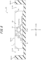
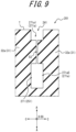
- FIGS. 8 and 9 illustrate a sipe 241 of the tire 201.
- FIG. 8 is a cross-sectional view in the same position as FIG. 3 .
- FIG. 9 is a drawing illustrating a widened portion 251 of the sipe 241 in cross section that is perpendicular to the cross section illustrated in FIG. 8 and parallel to the tire radial direction A.
- the tire 201 of the present embodiment of the invention differs in the configuration of the widened portion and shares other configurations. Therefore, here, the difference from the tire 1 of the first embodiment is mainly explained, and the common points are omitted.
- the sipe 241 is provided with the widened portion 251 the sipe width of which is larger than positions adjacent in the sipe longitudinal direction D.
- the cross-sectional area of the widened portion 251 in cross section perpendicular to the tire radial direction A is larger on the inside than on the outside in the tire radial direction A. This point is the same as that of the widened portion 51 of the first embodiment.
- the widened portion 251 of the present invention has a branch tubular portion 271 that branches into a plurality of portions in the sipe longitudinal direction D from the outside to the inside in the tire radial direction A.
- tubular pieces 271a are branched and increased from the outside to the inside in the tire radial direction A, so that the cross-sectional area of the branch tubular portion 271 in cross section perpendicular to the tire radial direction A increases.
- Each of the tubular pieces 271a, which constitute the branch tubular portion 271 has a larger sipe width than positions adjacent in the sipe longitudinal direction D, as in the tubular portion 52 of the first embodiment.
- each tubular piece 271a of the branch tubular portion 271 The number of branches from each tubular piece 271a of the branch tubular portion 271, the shape and cross-sectional area of each tubular piece 271a in cross section perpendicular to the tire radial direction A, and the like are not particularly limited. That is, the configuration of each tubular piece 271a is not particularly limited as long as the cross-sectional area of the branch tubular portion 271 in cross section perpendicular to the tire radial direction A is larger on the inside than on the outside in the tire radial direction A. Note that, in the sipe 241 of the present invention, parts where the branch tubular portion 271 is not provided and parts between the six tubular pieces 271a are composed of slits 53.
- the branch tubular portion 271 of the present invention extends from a bottom of the sipe to the surface of the tread land portion 31. More specifically, in the branch tubular portion 271 of the present invention, one first tubular piece 271a1 extends from the surface of the tread land portion 31 inwardly in the tire radial direction A. An inner end of the one first tubular piece 271a1 in the tire radial direction A is branched in two into a second tubular piece 271a2 and a third tubular piece 271a3. An inner end of the second tubular piece 271a2 in the tire radial direction A is branched in two into a fourth tubular piece 271a4 and a fifth tubular piece 271a5.
- An inner end of the third tubular piece 271a3 in the tire radial direction A is branched in two into the fifth tubular piece 271a5 and a sixth tubular piece 271a6.
- the fifth tubular piece 271a5 is a tubular piece that is branched from each of the second tubular pieces 271a2 and the third tubular piece 271a3 and merged into one.
- inner ends of the first to sixth tube pieces 271a1 to 271a6 in the tire radial direction A have an approximately equal shape and cross-sectional area in cross section perpendicular to the tire radial direction A. Therefore, the cross-sectional area of the branch tubular portion 271 in cross section perpendicular to the tire radial direction A is larger on the inside than on the outside in the tire radial direction A.
- the sipe 241 of the present invention is provided with only one of the branch tubular portion 271, but is not limited to this configuration.
- a plurality of the branch tubular portions 271 may be provided at different positions in the sipe longitudinal direction D. That is, the sipe 241 should have at least one of the branch tubular portion 271.
- the number of the branch tubular portions 271 provided in the single sipe 241 may be determined as appropriate according to the length of the sipe 241 in the sipe longitudinal direction D and other factors.
- the tire of the present invention is not limited to the specific configurations illustrated in the embodiments described above, but can be transformed and modified in various ways as long as it does not depart from the scope of the claims.
- the sipes 41, 141, and 241 are formed in the center land portion 32a as the tread land portion, but may be formed in the intermediate land portions 32b or the shoulder land portions 32c.
- the sipes 41, 141, and 241 of the first to third embodiments described above are formed in the rib-shaped land portion, but may be formed in a block-shaped land portion.
- the present invention relates to a tire.
Landscapes
- Engineering & Computer Science (AREA)
- Mechanical Engineering (AREA)
- Tires In General (AREA)
Applications Claiming Priority (2)
| Application Number | Priority Date | Filing Date | Title |
|---|---|---|---|
| JP2019224893A JP7284698B2 (ja) | 2019-12-12 | 2019-12-12 | タイヤ |
| PCT/JP2020/027137 WO2021117282A1 (ja) | 2019-12-12 | 2020-07-10 | タイヤ |
Publications (3)
| Publication Number | Publication Date |
|---|---|
| EP4049862A1 EP4049862A1 (en) | 2022-08-31 |
| EP4049862A4 EP4049862A4 (en) | 2022-11-16 |
| EP4049862B1 true EP4049862B1 (en) | 2024-09-04 |
Family
ID=76312933
Family Applications (1)
| Application Number | Title | Priority Date | Filing Date |
|---|---|---|---|
| EP20899208.1A Active EP4049862B1 (en) | 2019-12-12 | 2020-07-10 | Tire |
Country Status (5)
| Country | Link |
|---|---|
| US (1) | US12054010B2 (https=) |
| EP (1) | EP4049862B1 (https=) |
| JP (1) | JP7284698B2 (https=) |
| CN (1) | CN114786965B (https=) |
| WO (1) | WO2021117282A1 (https=) |
Families Citing this family (2)
| Publication number | Priority date | Publication date | Assignee | Title |
|---|---|---|---|---|
| DE102022213954A1 (de) * | 2022-12-19 | 2024-06-20 | Continental Reifen Deutschland Gmbh | Fahrzeugluftreifen |
| EP4733088A1 (en) | 2024-10-22 | 2026-04-29 | Nokian Renkaat Oyj | A tyre having sipes, and a lamella plate |
Family Cites Families (34)
| Publication number | Priority date | Publication date | Assignee | Title |
|---|---|---|---|---|
| JP2754040B2 (ja) * | 1989-05-30 | 1998-05-20 | 東洋ゴム工業株式会社 | 空気入りタイヤ成形用金型 |
| FR2683771B1 (fr) * | 1991-11-18 | 1994-01-07 | Michelin & Cie | Bande de roulement pourvue de rainures dont les parois sont munies d'incisions. |
| JP2000211320A (ja) * | 1999-01-21 | 2000-08-02 | Bridgestone Corp | 空気入りタイヤ及びサイプ用ブレ―ド |
| FR2801531A1 (fr) | 1999-11-25 | 2001-06-01 | Michelin Soc Tech | Moule de bande de roulement |
| US6631746B2 (en) * | 2001-04-25 | 2003-10-14 | Bridgestone/Firestone North American Tire, Llc | Undercut tie bar for pneumatic tire |
| CN100532139C (zh) * | 2003-05-21 | 2009-08-26 | 株式会社普利司通 | 充气轮胎及设计其胎面花纹的方法 |
| JP2006188185A (ja) * | 2005-01-07 | 2006-07-20 | Bridgestone Corp | 空気入りタイヤ |
| JP5013967B2 (ja) * | 2007-05-24 | 2012-08-29 | 株式会社ブリヂストン | 空気入りタイヤ |
| JP5156315B2 (ja) | 2007-09-26 | 2013-03-06 | 株式会社ブリヂストン | 空気入りタイヤ |
| JP2009280035A (ja) | 2008-05-21 | 2009-12-03 | Yokohama Rubber Co Ltd:The | 空気入りタイヤ |
| JP5563074B2 (ja) * | 2009-06-12 | 2014-07-30 | コンパニー ゼネラール デ エタブリッスマン ミシュラン | 扇形切欠部を有するプログレッシブ・タイヤ成形要素および同成形要素により形成されるタイヤ |
| RU2521455C2 (ru) * | 2009-10-20 | 2014-06-27 | Бриджстоун Корпорейшн | Пневматическая шина |
| JP2012001030A (ja) * | 2010-06-15 | 2012-01-05 | Yokohama Rubber Co Ltd:The | 空気入りタイヤ |
| FR2971732B1 (fr) | 2011-02-17 | 2013-02-01 | Michelin Soc Tech | Bande de roulement pour pneumatique poids lourd de type remorque et element moulant |
| US9744811B2 (en) | 2011-06-30 | 2017-08-29 | Compagnie Generale Des Etablissements Michelin | Tire tread having groove with internal voids |
| JP2013126842A (ja) | 2011-12-19 | 2013-06-27 | Bridgestone Corp | 空気入りタイヤ |
| FR2995253B1 (fr) * | 2012-09-13 | 2015-01-16 | Michelin & Cie | Bande de roulement et pneu pour poids lourd |
| FR2998511B1 (fr) * | 2012-11-29 | 2014-12-26 | Michelin & Cie | Bande de roulement pour pneumatique neige comportant des incisions et des cavites |
| FR3014746B1 (fr) | 2013-12-13 | 2017-08-11 | Michelin & Cie | Bande de roulement evolutive pour pneu. |
| FR3014747B1 (fr) | 2013-12-13 | 2015-12-11 | Michelin & Cie | Bande de roulement evolutive pour pneu |
| WO2017039679A1 (en) * | 2015-09-04 | 2017-03-09 | Compagnie Generale Des Etablissements Michelin | Truck tire tread and truck tire |
| JP6554017B2 (ja) | 2015-11-05 | 2019-07-31 | Toyo Tire株式会社 | 空気入りタイヤ |
| JP6585472B2 (ja) * | 2015-11-05 | 2019-10-02 | Toyo Tire株式会社 | 空気入りタイヤ |
| CN109070650B (zh) | 2016-04-18 | 2021-06-01 | 株式会社普利司通 | 轮胎 |
| JP6697939B2 (ja) | 2016-04-18 | 2020-05-27 | 株式会社ブリヂストン | タイヤ |
| JP6844329B2 (ja) * | 2017-03-06 | 2021-03-17 | 横浜ゴム株式会社 | 空気入りタイヤ |
| JP7076444B2 (ja) | 2017-06-19 | 2022-05-27 | 株式会社ブリヂストン | タイヤ |
| JP6953298B2 (ja) * | 2017-12-12 | 2021-10-27 | 株式会社ブリヂストン | 空気入りタイヤ |
| JP7081185B2 (ja) | 2018-02-05 | 2022-06-07 | 住友ゴム工業株式会社 | タイヤ |
| KR102080390B1 (ko) * | 2018-04-26 | 2020-02-21 | 한국타이어앤테크놀로지 주식회사 | 웨트 그립 강화 타이어 |
| DE102018217712A1 (de) * | 2018-10-17 | 2020-04-23 | Continental Reifen Deutschland Gmbh | Fahrzeugluftreifen |
| WO2020128281A1 (fr) * | 2018-12-21 | 2020-06-25 | Compagnie Generale Des Etablissements Michelin | Bande de roulement de pneu pour poids lourd ayant des incisions ameliorees |
| JP7177009B2 (ja) * | 2019-06-14 | 2022-11-22 | 株式会社ブリヂストン | 空気入りタイヤ |
| DE102019211027A1 (de) * | 2019-07-25 | 2021-01-28 | Continental Reifen Deutschland Gmbh | Fahrzeugluftreifen |
-
2019
- 2019-12-12 JP JP2019224893A patent/JP7284698B2/ja active Active
-
2020
- 2020-07-10 US US17/756,777 patent/US12054010B2/en active Active
- 2020-07-10 WO PCT/JP2020/027137 patent/WO2021117282A1/ja not_active Ceased
- 2020-07-10 CN CN202080085079.6A patent/CN114786965B/zh active Active
- 2020-07-10 EP EP20899208.1A patent/EP4049862B1/en active Active
Also Published As
| Publication number | Publication date |
|---|---|
| JP2021091375A (ja) | 2021-06-17 |
| JP7284698B2 (ja) | 2023-05-31 |
| US12054010B2 (en) | 2024-08-06 |
| EP4049862A4 (en) | 2022-11-16 |
| EP4049862A1 (en) | 2022-08-31 |
| US20230001746A1 (en) | 2023-01-05 |
| WO2021117282A1 (ja) | 2021-06-17 |
| CN114786965B (zh) | 2023-08-25 |
| CN114786965A (zh) | 2022-07-22 |
Similar Documents
| Publication | Publication Date | Title |
|---|---|---|
| EP2716477B1 (en) | Pneumatic tire | |
| US10105992B2 (en) | Pneumatic tire | |
| JP5841568B2 (ja) | 空気入りタイヤ | |
| US11548323B2 (en) | Pneumatic tire | |
| US10245894B2 (en) | Pneumatic tire | |
| US9061550B2 (en) | Pneumatic tire | |
| EP2623339B1 (en) | Motorcycle tire | |
| EP3415342B1 (en) | Heavy-duty tire | |
| EP4049862B1 (en) | Tire | |
| US12508848B2 (en) | Pneumatic tire | |
| EP3599112B1 (en) | Studless tyre | |
| US20250042203A1 (en) | Tire | |
| EP4043243B1 (en) | Pneumatic tire | |
| EP3785941A1 (en) | Stud pin and stud tire | |
| EP4049861B1 (en) | Tire | |
| EP4105039B1 (en) | Tire and tire-vehicle combination | |
| US11919335B2 (en) | Pneumatic tire | |
| EP3995327B1 (en) | Pneumatic tire | |
| US11077713B2 (en) | Tire | |
| JPH07285304A (ja) | 空気入りラジアルタイヤ |
Legal Events
| Date | Code | Title | Description |
|---|---|---|---|
| STAA | Information on the status of an ep patent application or granted ep patent |
Free format text: STATUS: THE INTERNATIONAL PUBLICATION HAS BEEN MADE |
|
| PUAI | Public reference made under article 153(3) epc to a published international application that has entered the european phase |
Free format text: ORIGINAL CODE: 0009012 |
|
| STAA | Information on the status of an ep patent application or granted ep patent |
Free format text: STATUS: REQUEST FOR EXAMINATION WAS MADE |
|
| 17P | Request for examination filed |
Effective date: 20220524 |
|
| AK | Designated contracting states |
Kind code of ref document: A1 Designated state(s): AL AT BE BG CH CY CZ DE DK EE ES FI FR GB GR HR HU IE IS IT LI LT LU LV MC MK MT NL NO PL PT RO RS SE SI SK SM TR |
|
| A4 | Supplementary search report drawn up and despatched |
Effective date: 20221019 |
|
| RIC1 | Information provided on ipc code assigned before grant |
Ipc: B60C 11/12 20060101ALI20221013BHEP Ipc: B60C 11/03 20060101AFI20221013BHEP |
|
| DAV | Request for validation of the european patent (deleted) | ||
| DAX | Request for extension of the european patent (deleted) | ||
| GRAP | Despatch of communication of intention to grant a patent |
Free format text: ORIGINAL CODE: EPIDOSNIGR1 |
|
| STAA | Information on the status of an ep patent application or granted ep patent |
Free format text: STATUS: GRANT OF PATENT IS INTENDED |
|
| INTG | Intention to grant announced |
Effective date: 20240216 |
|
| P01 | Opt-out of the competence of the unified patent court (upc) registered |
Effective date: 20240227 |
|
| GRAS | Grant fee paid |
Free format text: ORIGINAL CODE: EPIDOSNIGR3 |
|
| GRAA | (expected) grant |
Free format text: ORIGINAL CODE: 0009210 |
|
| STAA | Information on the status of an ep patent application or granted ep patent |
Free format text: STATUS: THE PATENT HAS BEEN GRANTED |
|
| AK | Designated contracting states |
Kind code of ref document: B1 Designated state(s): AL AT BE BG CH CY CZ DE DK EE ES FI FR GB GR HR HU IE IS IT LI LT LU LV MC MK MT NL NO PL PT RO RS SE SI SK SM TR |
|
| REG | Reference to a national code |
Ref country code: GB Ref legal event code: FG4D |
|
| REG | Reference to a national code |
Ref country code: CH Ref legal event code: EP |
|
| REG | Reference to a national code |
Ref country code: IE Ref legal event code: FG4D |
|
| REG | Reference to a national code |
Ref country code: DE Ref legal event code: R096 Ref document number: 602020037332 Country of ref document: DE |
|
| REG | Reference to a national code |
Ref country code: LT Ref legal event code: MG9D |
|
| REG | Reference to a national code |
Ref country code: NL Ref legal event code: MP Effective date: 20240904 |
|
| PG25 | Lapsed in a contracting state [announced via postgrant information from national office to epo] |
Ref country code: NO Free format text: LAPSE BECAUSE OF FAILURE TO SUBMIT A TRANSLATION OF THE DESCRIPTION OR TO PAY THE FEE WITHIN THE PRESCRIBED TIME-LIMIT Effective date: 20241204 |
|
| PG25 | Lapsed in a contracting state [announced via postgrant information from national office to epo] |
Ref country code: GR Free format text: LAPSE BECAUSE OF FAILURE TO SUBMIT A TRANSLATION OF THE DESCRIPTION OR TO PAY THE FEE WITHIN THE PRESCRIBED TIME-LIMIT Effective date: 20241205 Ref country code: PL Free format text: LAPSE BECAUSE OF FAILURE TO SUBMIT A TRANSLATION OF THE DESCRIPTION OR TO PAY THE FEE WITHIN THE PRESCRIBED TIME-LIMIT Effective date: 20240904 Ref country code: FI Free format text: LAPSE BECAUSE OF FAILURE TO SUBMIT A TRANSLATION OF THE DESCRIPTION OR TO PAY THE FEE WITHIN THE PRESCRIBED TIME-LIMIT Effective date: 20240904 |
|
| PG25 | Lapsed in a contracting state [announced via postgrant information from national office to epo] |
Ref country code: BG Free format text: LAPSE BECAUSE OF FAILURE TO SUBMIT A TRANSLATION OF THE DESCRIPTION OR TO PAY THE FEE WITHIN THE PRESCRIBED TIME-LIMIT Effective date: 20240904 |
|
| PG25 | Lapsed in a contracting state [announced via postgrant information from national office to epo] |
Ref country code: LV Free format text: LAPSE BECAUSE OF FAILURE TO SUBMIT A TRANSLATION OF THE DESCRIPTION OR TO PAY THE FEE WITHIN THE PRESCRIBED TIME-LIMIT Effective date: 20240904 |
|
| PG25 | Lapsed in a contracting state [announced via postgrant information from national office to epo] |
Ref country code: HR Free format text: LAPSE BECAUSE OF FAILURE TO SUBMIT A TRANSLATION OF THE DESCRIPTION OR TO PAY THE FEE WITHIN THE PRESCRIBED TIME-LIMIT Effective date: 20240904 |
|
| PG25 | Lapsed in a contracting state [announced via postgrant information from national office to epo] |
Ref country code: ES Free format text: LAPSE BECAUSE OF FAILURE TO SUBMIT A TRANSLATION OF THE DESCRIPTION OR TO PAY THE FEE WITHIN THE PRESCRIBED TIME-LIMIT Effective date: 20240904 Ref country code: RS Free format text: LAPSE BECAUSE OF FAILURE TO SUBMIT A TRANSLATION OF THE DESCRIPTION OR TO PAY THE FEE WITHIN THE PRESCRIBED TIME-LIMIT Effective date: 20241204 |
|
| PG25 | Lapsed in a contracting state [announced via postgrant information from national office to epo] |
Ref country code: RS Free format text: LAPSE BECAUSE OF FAILURE TO SUBMIT A TRANSLATION OF THE DESCRIPTION OR TO PAY THE FEE WITHIN THE PRESCRIBED TIME-LIMIT Effective date: 20241204 Ref country code: PL Free format text: LAPSE BECAUSE OF FAILURE TO SUBMIT A TRANSLATION OF THE DESCRIPTION OR TO PAY THE FEE WITHIN THE PRESCRIBED TIME-LIMIT Effective date: 20240904 Ref country code: NO Free format text: LAPSE BECAUSE OF FAILURE TO SUBMIT A TRANSLATION OF THE DESCRIPTION OR TO PAY THE FEE WITHIN THE PRESCRIBED TIME-LIMIT Effective date: 20241204 Ref country code: LV Free format text: LAPSE BECAUSE OF FAILURE TO SUBMIT A TRANSLATION OF THE DESCRIPTION OR TO PAY THE FEE WITHIN THE PRESCRIBED TIME-LIMIT Effective date: 20240904 Ref country code: HR Free format text: LAPSE BECAUSE OF FAILURE TO SUBMIT A TRANSLATION OF THE DESCRIPTION OR TO PAY THE FEE WITHIN THE PRESCRIBED TIME-LIMIT Effective date: 20240904 Ref country code: GR Free format text: LAPSE BECAUSE OF FAILURE TO SUBMIT A TRANSLATION OF THE DESCRIPTION OR TO PAY THE FEE WITHIN THE PRESCRIBED TIME-LIMIT Effective date: 20241205 Ref country code: FI Free format text: LAPSE BECAUSE OF FAILURE TO SUBMIT A TRANSLATION OF THE DESCRIPTION OR TO PAY THE FEE WITHIN THE PRESCRIBED TIME-LIMIT Effective date: 20240904 Ref country code: ES Free format text: LAPSE BECAUSE OF FAILURE TO SUBMIT A TRANSLATION OF THE DESCRIPTION OR TO PAY THE FEE WITHIN THE PRESCRIBED TIME-LIMIT Effective date: 20240904 Ref country code: BG Free format text: LAPSE BECAUSE OF FAILURE TO SUBMIT A TRANSLATION OF THE DESCRIPTION OR TO PAY THE FEE WITHIN THE PRESCRIBED TIME-LIMIT Effective date: 20240904 |
|
| REG | Reference to a national code |
Ref country code: AT Ref legal event code: MK05 Ref document number: 1720008 Country of ref document: AT Kind code of ref document: T Effective date: 20240904 |
|
| PG25 | Lapsed in a contracting state [announced via postgrant information from national office to epo] |
Ref country code: NL Free format text: LAPSE BECAUSE OF FAILURE TO SUBMIT A TRANSLATION OF THE DESCRIPTION OR TO PAY THE FEE WITHIN THE PRESCRIBED TIME-LIMIT Effective date: 20240904 |
|
| PG25 | Lapsed in a contracting state [announced via postgrant information from national office to epo] |
Ref country code: PT Free format text: LAPSE BECAUSE OF FAILURE TO SUBMIT A TRANSLATION OF THE DESCRIPTION OR TO PAY THE FEE WITHIN THE PRESCRIBED TIME-LIMIT Effective date: 20250106 Ref country code: IS Free format text: LAPSE BECAUSE OF FAILURE TO SUBMIT A TRANSLATION OF THE DESCRIPTION OR TO PAY THE FEE WITHIN THE PRESCRIBED TIME-LIMIT Effective date: 20250104 |
|
| PG25 | Lapsed in a contracting state [announced via postgrant information from national office to epo] |
Ref country code: RO Free format text: LAPSE BECAUSE OF FAILURE TO SUBMIT A TRANSLATION OF THE DESCRIPTION OR TO PAY THE FEE WITHIN THE PRESCRIBED TIME-LIMIT Effective date: 20240904 Ref country code: SM Free format text: LAPSE BECAUSE OF FAILURE TO SUBMIT A TRANSLATION OF THE DESCRIPTION OR TO PAY THE FEE WITHIN THE PRESCRIBED TIME-LIMIT Effective date: 20240904 |
|
| PG25 | Lapsed in a contracting state [announced via postgrant information from national office to epo] |
Ref country code: EE Free format text: LAPSE BECAUSE OF FAILURE TO SUBMIT A TRANSLATION OF THE DESCRIPTION OR TO PAY THE FEE WITHIN THE PRESCRIBED TIME-LIMIT Effective date: 20240904 Ref country code: AT Free format text: LAPSE BECAUSE OF FAILURE TO SUBMIT A TRANSLATION OF THE DESCRIPTION OR TO PAY THE FEE WITHIN THE PRESCRIBED TIME-LIMIT Effective date: 20240904 |
|
| PG25 | Lapsed in a contracting state [announced via postgrant information from national office to epo] |
Ref country code: CZ Free format text: LAPSE BECAUSE OF FAILURE TO SUBMIT A TRANSLATION OF THE DESCRIPTION OR TO PAY THE FEE WITHIN THE PRESCRIBED TIME-LIMIT Effective date: 20240904 |
|
| PG25 | Lapsed in a contracting state [announced via postgrant information from national office to epo] |
Ref country code: SK Free format text: LAPSE BECAUSE OF FAILURE TO SUBMIT A TRANSLATION OF THE DESCRIPTION OR TO PAY THE FEE WITHIN THE PRESCRIBED TIME-LIMIT Effective date: 20240904 Ref country code: IT Free format text: LAPSE BECAUSE OF FAILURE TO SUBMIT A TRANSLATION OF THE DESCRIPTION OR TO PAY THE FEE WITHIN THE PRESCRIBED TIME-LIMIT Effective date: 20240904 |
|
| REG | Reference to a national code |
Ref country code: DE Ref legal event code: R097 Ref document number: 602020037332 Country of ref document: DE |
|
| PG25 | Lapsed in a contracting state [announced via postgrant information from national office to epo] |
Ref country code: DK Free format text: LAPSE BECAUSE OF FAILURE TO SUBMIT A TRANSLATION OF THE DESCRIPTION OR TO PAY THE FEE WITHIN THE PRESCRIBED TIME-LIMIT Effective date: 20240904 |
|
| PLBE | No opposition filed within time limit |
Free format text: ORIGINAL CODE: 0009261 |
|
| STAA | Information on the status of an ep patent application or granted ep patent |
Free format text: STATUS: NO OPPOSITION FILED WITHIN TIME LIMIT |
|
| 26N | No opposition filed |
Effective date: 20250605 |
|
| PG25 | Lapsed in a contracting state [announced via postgrant information from national office to epo] |
Ref country code: SE Free format text: LAPSE BECAUSE OF FAILURE TO SUBMIT A TRANSLATION OF THE DESCRIPTION OR TO PAY THE FEE WITHIN THE PRESCRIBED TIME-LIMIT Effective date: 20240904 |
|
| PGFP | Annual fee paid to national office [announced via postgrant information from national office to epo] |
Ref country code: DE Payment date: 20250722 Year of fee payment: 6 |
|
| PGFP | Annual fee paid to national office [announced via postgrant information from national office to epo] |
Ref country code: FR Payment date: 20250725 Year of fee payment: 6 |
|
| REG | Reference to a national code |
Ref country code: CH Ref legal event code: H13 Free format text: ST27 STATUS EVENT CODE: U-0-0-H10-H13 (AS PROVIDED BY THE NATIONAL OFFICE) Effective date: 20260224 |
|
| PG25 | Lapsed in a contracting state [announced via postgrant information from national office to epo] |
Ref country code: LU Free format text: LAPSE BECAUSE OF NON-PAYMENT OF DUE FEES Effective date: 20250710 |
|
| GBPC | Gb: european patent ceased through non-payment of renewal fee |
Effective date: 20250710 |
|
| REG | Reference to a national code |
Ref country code: BE Ref legal event code: MM Effective date: 20250731 |
|
| PG25 | Lapsed in a contracting state [announced via postgrant information from national office to epo] |
Ref country code: GB Free format text: LAPSE BECAUSE OF NON-PAYMENT OF DUE FEES Effective date: 20250710 |
|
| PG25 | Lapsed in a contracting state [announced via postgrant information from national office to epo] |
Ref country code: BE Free format text: LAPSE BECAUSE OF NON-PAYMENT OF DUE FEES Effective date: 20250731 |
|
| PG25 | Lapsed in a contracting state [announced via postgrant information from national office to epo] |
Ref country code: CH Free format text: LAPSE BECAUSE OF NON-PAYMENT OF DUE FEES Effective date: 20250731 |