EP4048580B1 - Antriebssystem für ein seitlich montiertes fahrradrad - Google Patents
Antriebssystem für ein seitlich montiertes fahrradrad Download PDFInfo
- Publication number
- EP4048580B1 EP4048580B1 EP20800249.3A EP20800249A EP4048580B1 EP 4048580 B1 EP4048580 B1 EP 4048580B1 EP 20800249 A EP20800249 A EP 20800249A EP 4048580 B1 EP4048580 B1 EP 4048580B1
- Authority
- EP
- European Patent Office
- Prior art keywords
- wheel hub
- motor
- side mounted
- wheel
- rotary wheel
- Prior art date
- Legal status (The legal status is an assumption and is not a legal conclusion. Google has not performed a legal analysis and makes no representation as to the accuracy of the status listed.)
- Active
Links
Images

Classifications
-
- B—PERFORMING OPERATIONS; TRANSPORTING
- B62—LAND VEHICLES FOR TRAVELLING OTHERWISE THAN ON RAILS
- B62K—CYCLES; CYCLE FRAMES; CYCLE STEERING DEVICES; RIDER-OPERATED TERMINAL CONTROLS SPECIALLY ADAPTED FOR CYCLES; CYCLE AXLE SUSPENSIONS; CYCLE SIDE-CARS, FORECARS, OR THE LIKE
- B62K25/00—Axle suspensions
- B62K25/005—Axle suspensions characterised by the axle being supported at one end only
-
- B—PERFORMING OPERATIONS; TRANSPORTING
- B60—VEHICLES IN GENERAL
- B60K—ARRANGEMENT OR MOUNTING OF PROPULSION UNITS OR OF TRANSMISSIONS IN VEHICLES; ARRANGEMENT OR MOUNTING OF PLURAL DIVERSE PRIME-MOVERS IN VEHICLES; AUXILIARY DRIVES FOR VEHICLES; INSTRUMENTATION OR DASHBOARDS FOR VEHICLES; ARRANGEMENTS IN CONNECTION WITH COOLING, AIR INTAKE, GAS EXHAUST OR FUEL SUPPLY OF PROPULSION UNITS IN VEHICLES
- B60K17/00—Arrangement or mounting of transmissions in vehicles
- B60K17/04—Arrangement or mounting of transmissions in vehicles characterised by arrangement, location or kind of gearing
- B60K17/043—Transmission unit disposed in on near the vehicle wheel, or between the differential gear unit and the wheel
- B60K17/046—Transmission unit disposed in on near the vehicle wheel, or between the differential gear unit and the wheel with planetary gearing having orbital motion
-
- B—PERFORMING OPERATIONS; TRANSPORTING
- B60—VEHICLES IN GENERAL
- B60K—ARRANGEMENT OR MOUNTING OF PROPULSION UNITS OR OF TRANSMISSIONS IN VEHICLES; ARRANGEMENT OR MOUNTING OF PLURAL DIVERSE PRIME-MOVERS IN VEHICLES; AUXILIARY DRIVES FOR VEHICLES; INSTRUMENTATION OR DASHBOARDS FOR VEHICLES; ARRANGEMENTS IN CONNECTION WITH COOLING, AIR INTAKE, GAS EXHAUST OR FUEL SUPPLY OF PROPULSION UNITS IN VEHICLES
- B60K7/00—Disposition of motor in, or adjacent to, traction wheel
- B60K7/0007—Disposition of motor in, or adjacent to, traction wheel the motor being electric
-
- B—PERFORMING OPERATIONS; TRANSPORTING
- B60—VEHICLES IN GENERAL
- B60L—PROPULSION OF ELECTRICALLY-PROPELLED VEHICLES; SUPPLYING ELECTRIC POWER FOR AUXILIARY EQUIPMENT OF ELECTRICALLY-PROPELLED VEHICLES; ELECTRODYNAMIC BRAKE SYSTEMS FOR VEHICLES IN GENERAL; MAGNETIC SUSPENSION OR LEVITATION FOR VEHICLES; MONITORING OPERATING VARIABLES OF ELECTRICALLY-PROPELLED VEHICLES; ELECTRIC SAFETY DEVICES FOR ELECTRICALLY-PROPELLED VEHICLES
- B60L50/00—Electric propulsion with power supplied within the vehicle
- B60L50/20—Electric propulsion with power supplied within the vehicle using propulsion power generated by humans or animals
-
- B—PERFORMING OPERATIONS; TRANSPORTING
- B62—LAND VEHICLES FOR TRAVELLING OTHERWISE THAN ON RAILS
- B62M—RIDER PROPULSION OF WHEELED VEHICLES OR SLEDGES; POWERED PROPULSION OF SLEDGES OR SINGLE-TRACK CYCLES; TRANSMISSIONS SPECIALLY ADAPTED FOR SUCH VEHICLES
- B62M6/00—Rider propulsion of wheeled vehicles with additional source of power, e.g. combustion engine or electric motor
- B62M6/40—Rider propelled cycles with auxiliary electric motor
- B62M6/60—Rider propelled cycles with auxiliary electric motor power-driven at axle parts
- B62M6/65—Rider propelled cycles with auxiliary electric motor power-driven at axle parts with axle and driving shaft arranged coaxially
-
- B—PERFORMING OPERATIONS; TRANSPORTING
- B62—LAND VEHICLES FOR TRAVELLING OTHERWISE THAN ON RAILS
- B62M—RIDER PROPULSION OF WHEELED VEHICLES OR SLEDGES; POWERED PROPULSION OF SLEDGES OR SINGLE-TRACK CYCLES; TRANSMISSIONS SPECIALLY ADAPTED FOR SUCH VEHICLES
- B62M6/00—Rider propulsion of wheeled vehicles with additional source of power, e.g. combustion engine or electric motor
- B62M6/40—Rider propelled cycles with auxiliary electric motor
- B62M6/75—Rider propelled cycles with auxiliary electric motor power-driven by friction rollers or gears engaging the ground wheel
-
- B—PERFORMING OPERATIONS; TRANSPORTING
- B60—VEHICLES IN GENERAL
- B60K—ARRANGEMENT OR MOUNTING OF PROPULSION UNITS OR OF TRANSMISSIONS IN VEHICLES; ARRANGEMENT OR MOUNTING OF PLURAL DIVERSE PRIME-MOVERS IN VEHICLES; AUXILIARY DRIVES FOR VEHICLES; INSTRUMENTATION OR DASHBOARDS FOR VEHICLES; ARRANGEMENTS IN CONNECTION WITH COOLING, AIR INTAKE, GAS EXHAUST OR FUEL SUPPLY OF PROPULSION UNITS IN VEHICLES
- B60K7/00—Disposition of motor in, or adjacent to, traction wheel
- B60K2007/0038—Disposition of motor in, or adjacent to, traction wheel the motor moving together with the wheel axle
-
- B—PERFORMING OPERATIONS; TRANSPORTING
- B60—VEHICLES IN GENERAL
- B60K—ARRANGEMENT OR MOUNTING OF PROPULSION UNITS OR OF TRANSMISSIONS IN VEHICLES; ARRANGEMENT OR MOUNTING OF PLURAL DIVERSE PRIME-MOVERS IN VEHICLES; AUXILIARY DRIVES FOR VEHICLES; INSTRUMENTATION OR DASHBOARDS FOR VEHICLES; ARRANGEMENTS IN CONNECTION WITH COOLING, AIR INTAKE, GAS EXHAUST OR FUEL SUPPLY OF PROPULSION UNITS IN VEHICLES
- B60K7/00—Disposition of motor in, or adjacent to, traction wheel
- B60K2007/0092—Disposition of motor in, or adjacent to, traction wheel the motor axle being coaxial to the wheel axle
-
- B—PERFORMING OPERATIONS; TRANSPORTING
- B60—VEHICLES IN GENERAL
- B60L—PROPULSION OF ELECTRICALLY-PROPELLED VEHICLES; SUPPLYING ELECTRIC POWER FOR AUXILIARY EQUIPMENT OF ELECTRICALLY-PROPELLED VEHICLES; ELECTRODYNAMIC BRAKE SYSTEMS FOR VEHICLES IN GENERAL; MAGNETIC SUSPENSION OR LEVITATION FOR VEHICLES; MONITORING OPERATING VARIABLES OF ELECTRICALLY-PROPELLED VEHICLES; ELECTRIC SAFETY DEVICES FOR ELECTRICALLY-PROPELLED VEHICLES
- B60L2200/00—Type of vehicles
- B60L2200/12—Bikes
-
- B—PERFORMING OPERATIONS; TRANSPORTING
- B60—VEHICLES IN GENERAL
- B60L—PROPULSION OF ELECTRICALLY-PROPELLED VEHICLES; SUPPLYING ELECTRIC POWER FOR AUXILIARY EQUIPMENT OF ELECTRICALLY-PROPELLED VEHICLES; ELECTRODYNAMIC BRAKE SYSTEMS FOR VEHICLES IN GENERAL; MAGNETIC SUSPENSION OR LEVITATION FOR VEHICLES; MONITORING OPERATING VARIABLES OF ELECTRICALLY-PROPELLED VEHICLES; ELECTRIC SAFETY DEVICES FOR ELECTRICALLY-PROPELLED VEHICLES
- B60L2220/00—Electrical machine types; Structures or applications thereof
- B60L2220/40—Electrical machine applications
- B60L2220/44—Wheel Hub motors, i.e. integrated in the wheel hub
-
- B—PERFORMING OPERATIONS; TRANSPORTING
- B60—VEHICLES IN GENERAL
- B60Y—INDEXING SCHEME RELATING TO ASPECTS CROSS-CUTTING VEHICLE TECHNOLOGY
- B60Y2200/00—Type of vehicle
- B60Y2200/10—Road Vehicles
- B60Y2200/13—Bicycles; Tricycles
Definitions
- the motor gearbox is mounted within the hub of the front bicycle wheel.
- This hub is generally similar to traditional motor-less front wheel hubs in that it is fitted with an axle suited for mounting to a double leg fork and the hub has holes in the hub flanges to accept the spokes of the bicycle wheel.
- the axle is rigidly mounted to the front fork ends and is able to transmit torque from the motor to the bicycle fork through its connection to the centre axle, thereby enabling the rider and bicycle to accelerate under motor power.
- Some existing side mounted front wheel electric motor drives house the planetary gears and motor within a large diameter front shaft and mounted on the outer diameter of the shaft are two rotary bearings that facilitate the front hub and wheel to rotate.
- the motor drive is connected to this outer wheel hub through an end of the larger oversized axle with a one way type bearing coupling.
- This arrangement has the limitation of requiring that the sun, planet, and ring gears be relatively small, and the drawback of this design is that these small gears can be limited in their ability to handle sufficiently high torques.
- WO 2009/027683 A1 discloses a drive system for a side mounted cycle wheel, comprising:a wheel hub for mounting the side mounted wheel and a motor drive for driving the side mounted wheel, the motor drive comprising an electric motor.
- a drive system for a side mounted wheel comprising a wheel hub for mounting the side mounted wheel; a motor drive for driving the side mounted wheel, the motor drive comprising an electric motor and a planetary gear reduction assembly positioned at least partially within the wheel hub and comprising one or more planetary gears; and, a rotary wheel hub bearing rotatably coupling the wheel hub to the motor drive, wherein the rotary wheel hub bearing is positioned laterally between the electric motor and the planetary gears.
- the hub bearing and shaft mounting arrangement of present invention addresses drawbacks of current side mounted wheel drive electric vehicle designs. Compared to known arrangements, which instead have a rotary bearing positioned around an outer circumference of a planetary gearbox, positioning the rotary wheel hub bearing in the region between the planetary gear system and the motor components facilitates the use of reasonably sized hub bearings whilst still allowing a sufficiently large diameter planetary gearbox design able to use quiet plastic gearing. This configuration makes use of the space available around the naturally small diameter motor pinion sun gear diameter, which also has the benefit of increasing the distance between the front wheel hub bearings to provide a more optimal spacing.
- a side mounted wheel can be coupled to the wheel hub, for example using a threaded connection or similar, such that the wheel hub is coaxial with a rotation axis of the wheel.
- the planetary gear reduction assembly may be entirely cased within the wheel hub, or part of it could be exposed.
- the motor may be connected to a battery or similar power source.
- the rotary wheel hub bearing is coaxial with a wheel rotation axis of the side mounted wheel.
- an inner diameter of the rotary wheel hub bearing is smaller than an outer diameter of a stator of the electric motor.
- an outer diameter of the rotary wheel hub bearing may also be smaller than an outer diameter of a stator of the electric motor.
- an inner diameter of the rotary wheel hub bearing is smaller than an outer diameter of the planetary gear reduction assembly.
- an outer diameter of the rotary wheel hub bearing may also be smaller than an outer diameter of the planetary gear reduction assembly.
- an inner diameter of the rotary wheel hub bearing is smaller than an outer diameter a planetary input flange of the planetary gear reduction assembly.
- an outer diameter of the rotary wheel hub bearing may also be smaller than an outer diameter a planetary input flange of the planetary gear reduction assembly.
- the motor drive further comprises a planetary input flange and a motor output flange coaxial with a wheel rotation axis of the side mounted wheel, and the planetary input flange and the motor output flange share a common interface with the internal surface of the rotary wheel hub bearing.
- the rotary wheel hub bearing may be a first rotary wheel hub bearing
- the drive system may further comprise a second rotary wheel hub bearing rotatably coupling the wheel hub to the motor drive.
- the second rotary wheel hub bearing is positioned on an opposing side of the planetary gear reduction assembly to the first rotary wheel hub bearing.
- a cycle comprising a side mounted wheel mounted to the wheel hub of the drive system of the first aspect.
- the side mounted wheel may be a front side mounted wheel.
- the side mounted wheel may be a rear side mounted wheel.
- the cycle is a pedal driven cycle.
- an electric vehicle comprising a side mounted wheel mounted to the wheel hub of the drive system of the first aspect.
- the electric vehicle may be an electric scooter.
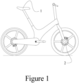
- Figure 1 shows a preferred embodiment of a single side mounted front motor drive bicycle 1 with a front side mounted motor assembly 2.
- Figure 2 shows an alternative view of the single side mounted front motor drive bicycle 1 of Figure 1 having a front single sided cantilevered fork member 3 facilitating the rigid mounting of the front side mounted motor assembly 2 and a front wheel brake calliper 6 for slowing a front wheel disk brake rotor 5 which is rigidly connected to a front single side wheel assembly 4.
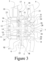
- FIG 3 is a vertical cross section front view of the front side mounted motor assembly 2 of Figures 1 and 2 through the front wheel rotation axis 7.
- the front side mounted motor assembly 2 comprises a front motor output housing 15 mounted by glue, press fitting, screw or bolt type fastener to the front single sided cantilevered fork member 3 able to receive a front motor housing 9.
- the front motor housing 9 is formed to house a front motor stator 10 and a front motor pinion outer bearing 14 which rotatably supports a front motor pinion 12 which is rigidly attached to a front motor magnet rotary 11.
- the interaction and control of the front motor stator 10 with respect to the front motor magnet rotary 11 is of the well-known and understood electric machine variety.
- the front motor pinion 12 is rotatably supported by the front motor pinion outer bearing 14 and a front motor pinion inner bearing 13 which is rotatably mounted to a front motor planet carrier 25.
- the front motor planet carrier is in turn supported by a front motor planetary gearbox input flange 22 through a front motor planet carrier inner bearing 27.
- the front motor planetary gearbox input flange 22 is rigidly attached to the front motor output housing 15 with a plurality of front motor fasteners 16.
- the front motor planetary gearbox input flange 22 is rigidly attached to a front motor planetary gearbox output flange 23 with a plurality of front motor gearbox output flange fasteners 24.
- the interface and connection of the front motor planetary gearbox input flange 22 with the front motor planetary gearbox output flange 23 could also be a threaded connection.
- the nature of the engagement and fitting of the front motor output housing 15 with the front motor planetary gearbox input flange 22 is such that the front motor output housing 15 and the front motor planetary gearbox input flange 22 share a common interface received by the internal diameter of a front wheel hub inner bearing 20.
- the front motor planet carrier 25 supports a front motor planet gear shaft 29 and a front motor planet gear 26 in a planetary gear arrangement to mesh with the front motor pinion 12 and the front motor planetary gearbox input flange 22 through a front motor planetary ring gear teeth component 31 such that output rotation speed of the front motor planet carrier 25 is reduced by a factor of between two and ten with respect to input rotation speed of the front motor pinion 12.
- the nature of the material of the front motor planet gear 26 is preferably plastic or of a low noise composite material.
- the nature of the material of the front motor pinion 12 is ideally metal such as stainless steel.
- the nature of the material of the front motor planetary gearbox input flange 22 could be ferrous metal or stainless steel metal or metal alloy.
- front motor planetary ring gear teeth component 31 could be of a number of different varieties such as the front motor planetary ring gear teeth component 31 being an integral part and similar material as the front motor planetary gearbox input flange 22 and constructed through gear hobbing processes, or the front motor planetary ring gear teeth component 31 could be of different material to the front motor planetary gearbox input flange 22, such as plastic, and constructed and attached to the front motor planetary gearbox input flange 22 through over moulding and keyed injection moulding connection.
- the front motor planet carrier 25 is further rotatably supported by a front motor planet carrier outer bearing 28 which is housed within the front motor planetary gearbox output flange 23.
- the front motor planet carrier 25 is rotatably connected to a front wheel hub outer 18 by a front motor one way clutch 30, for example a one way sprag type clutch, such that rotation of the front wheel hub outer 18 around the front wheel rotation axis 7 is only possible in one direction with respect to the front motor planet carrier 25.
- the front single side wheel assembly 4 is rigidly mounted on one side to the front wheel hub outer 18 with a front wheel assembly fastener 8.
- the front wheel hub outer 18 is rotatably mounted to the front motor planetary gearbox output flange 23 with a front wheel hub outer bearing 21 and rigidly connected to a front wheel hub inner 17 with a front disk rotor fastener 19 passing through the front wheel disk brake rotor 5.
- the front wheel hub inner 17 is rotatably mounted to the front motor output housing 15 and the front motor planetary gearbox input flange 22 by the front wheel hub inner bearing 20.
- the front wheel brake calliper 6 is arranged around the front wheel disk brake rotor 5 in a well-known fashion in order to provide braking force to the front single side wheel assembly 4.
- the position of the front wheel hub inner bearing 20 is generally to one side of the front motor planet gear 26 and to one side of the front motor stator 10 and the front motor magnet rotary 11, such that the front wheel hub inner bearing 20 is positioned laterally between the between the electric motor and the planetary gear system with at least a part of the electric motor on one side, for example the front motor stator 10, and at least part of the planetary gear system on the other side, for example the planetary front motor planet gears 26 or the front motor planet carrier 25.
- the front wheel hub inner bearing 20 is coaxial to the front wheel rotation axis 7 and is positioned in the region between the planetary gear system and the front motor stator 10 and front motor magnet rotary 11, such that the inner diameter of the front wheel hub inner bearing 20 is less than the respective outer diameters of the front motor stator 10 and the front motor planetary gearbox input flange 22.
- the wheel hub inner bearing 20 is axially located between the front motor stator 10 and the front motor planet gears 26, and radially located within the respective circumferences defined by the radially outer surfaces of the front motor stator 10 and the front motor planetary gearbox input flange 22.
- the motor assembly could be used in one or more of a non-pedal driven cycle, as a motor for a rear side mounted motor driven wheel, or as a motor for a side mounted front or rear wheel on an electric scooter, such as a small motorcycle (also referred to as a moped) that may have a drive system built into a rear suspension swing-arm.
Landscapes
- Engineering & Computer Science (AREA)
- Chemical & Material Sciences (AREA)
- Combustion & Propulsion (AREA)
- Mechanical Engineering (AREA)
- Transportation (AREA)
- Power Engineering (AREA)
- Arrangement Or Mounting Of Propulsion Units For Vehicles (AREA)
- Retarders (AREA)
- Connection Of Motors, Electrical Generators, Mechanical Devices, And The Like (AREA)
Claims (12)
- Antriebssystem für ein seitlich montiertes Fahrradrad, umfassend:eine drehbare Radnabe (24) zur Befestigung des seit-lich angebrachten Rades;einen Motorantrieb zum Antreiben des seitlich angebrachten Rades, wobei der Motorantrieb einen Elektromotor (10, 11) und eine Planetengetriebeuntersetzungsbaugruppe (25, 26, 31) umfasst, die mindestens teilweise innerhalb der drehbaren Radnabe (24) angeordnet ist und ein oder mehrere Planetengetriebe (26) und einen drehbaren Planetenträger (25) umfasst; und,ein drehbares Radnabenlager (20), das die drehbare Radnabe drehbar mit dem Motorantrieb verbindet,wobei das drehbare Radnabenlager (20) seitlich zwischen dem Elektromotor und den Planetengetrieben angeordnet ist; und,wobei die drehbare Radnabe (24) mit dem Planetenträger durch eine Einwegkupplung (30) verbunden ist, so dass eine Drehung der drehbaren Radnabe gegenüber dem Planetenträger nur in einer Richtung möglich ist.
- Antriebssystem nach einem der vorstehenden Ansprüche, wobei das drehbare Radnabenlager koaxial zu einer Raddrehachse des seitlich montierten Rades ist.
- Antriebssystem nach einem der vorstehenden Ansprüche, wobei der Innendurchmesser des drehbaren Radnabenlagers kleiner ist als der Außendurchmesser des Stators des Elektromotors.
- Antriebssystem nach einem der vorstehenden Ansprüche, wobei der Innendurchmesser des drehbaren Radnabenlagers kleiner ist als der Außendurchmesser der Planetengetriebeuntersetzungsbaugruppe.
- Antriebssystem nach einem der vorstehenden Ansprüche, wobei der Innendurchmesser des drehbaren Radnabenlagers kleiner ist als der Außendurchmesser des Planeteneingangsflansches der Planetengetriebeuntersetzungsbaugruppe.
- Antriebssystem nach einem der vorstehenden Ansprüche, wobei der Motorantrieb weiter einen Planeteneingangsflansch (22) und einen Motorabgangsflansch umfasst, die koaxial zu einer Raddrehachse des seitlich montierten Rades sind, und wobei der Planeteneingangsflansch und der Motorabgangsflansch eine gemeinsame Schnittstelle mit der Innenfläche des drehbaren Radnabenlagers haben.
- Antriebssystem nach einem der vorstehenden Ansprüche, wobei das drehbare Radnabenlager ein erstes drehbares Radnabenlager ist, und wobei das Antriebssystem weiter ein zweites drehbares Radnabenlager umfasst, das die Radnabe drehbar mit dem Motorantrieb verbindet.
- Antriebssystem nach Anspruch 7, wobei das zweite drehbare Radnabenlager auf einer dem ersten drehbaren Radnabenlager gegenüberliegenden Seite der Planetengetriebeuntersetzungsbaugruppe angeordnet ist.
- Fahrrad, umfassend:
ein seitlich montiertes Rad, das an der Radnabe des Antriebssystems nach einem der vorstehenden Ansprüche befestigt ist. - Fahrrad nach Anspruch 9, wobei das seitlich montierte Rad ein vorderes, seitlich montiertes Rad ist.
- Fahrrad nach Anspruch 10, wobei das seitlich montierte Rad ein hinteres, seitlich montiertes Rad ist.
- Fahrrad nach einem der Ansprüche 9 bis 11, wobei das Fahrrad ein pedalbetriebenes Fahrrad ist.
Applications Claiming Priority (2)
| Application Number | Priority Date | Filing Date | Title |
|---|---|---|---|
| GB1915272.7A GB2588411B (en) | 2019-10-22 | 2019-10-22 | Front motor drive bicycle with side mounted wheels |
| PCT/GB2020/052648 WO2021079113A1 (en) | 2019-10-22 | 2020-10-21 | Front motor drive bicycle with side mounted wheels |
Publications (2)
| Publication Number | Publication Date |
|---|---|
| EP4048580A1 EP4048580A1 (de) | 2022-08-31 |
| EP4048580B1 true EP4048580B1 (de) | 2024-08-28 |
Family
ID=68728352
Family Applications (1)
| Application Number | Title | Priority Date | Filing Date |
|---|---|---|---|
| EP20800249.3A Active EP4048580B1 (de) | 2019-10-22 | 2020-10-21 | Antriebssystem für ein seitlich montiertes fahrradrad |
Country Status (6)
| Country | Link |
|---|---|
| US (1) | US20220388597A1 (de) |
| EP (1) | EP4048580B1 (de) |
| JP (1) | JP7656597B2 (de) |
| CN (1) | CN114929570B (de) |
| GB (1) | GB2588411B (de) |
| WO (1) | WO2021079113A1 (de) |
Families Citing this family (2)
| Publication number | Priority date | Publication date | Assignee | Title |
|---|---|---|---|---|
| JP7486773B2 (ja) * | 2019-12-10 | 2024-05-20 | 株式会社アルミス | 電動アシスト自転車 |
| JP2024146535A (ja) * | 2023-03-31 | 2024-10-15 | 本田技研工業株式会社 | 鞍乗型車両 |
Family Cites Families (13)
| Publication number | Priority date | Publication date | Assignee | Title |
|---|---|---|---|---|
| JP4545968B2 (ja) | 2001-02-26 | 2010-09-15 | ヤマハ発動機株式会社 | ホイールモータの変速装置 |
| JP4524536B2 (ja) * | 2001-07-18 | 2010-08-18 | 日本精工株式会社 | 電動式車輪駆動装置 |
| JP3984139B2 (ja) * | 2001-10-19 | 2007-10-03 | ヤマハ発動機株式会社 | 電動二輪車の動力伝達装置 |
| JP2007022386A (ja) | 2005-07-19 | 2007-02-01 | Ntn Corp | 電動式車輪駆動装置 |
| JP4894215B2 (ja) * | 2005-10-05 | 2012-03-14 | 日産自動車株式会社 | インホイールドライブユニット |
| GB0717002D0 (en) * | 2007-08-31 | 2007-10-10 | Karbon Kinetics Ltd | Bicycle with motorised single leg front fork |
| KR20140038056A (ko) | 2012-09-19 | 2014-03-28 | 주식회사 만도 | 전기자전거용 구동 유닛 |
| KR20140038057A (ko) * | 2012-09-19 | 2014-03-28 | 주식회사 만도 | 전기자전거용 구동 유닛 |
| KR20140111447A (ko) * | 2013-03-11 | 2014-09-19 | 변동환 | 외팔보 전동 바퀴 구조 및 이를 포함하는 차량 |
| US9638285B2 (en) * | 2013-11-14 | 2017-05-02 | Razor Usa Llc | Hub motor arrangement or vehicle with hub motor arrangement |
| DE102015105331B4 (de) * | 2015-04-08 | 2023-02-16 | Ujet S.A. | Elektrischer Motorroller |
| CN109250028B (zh) * | 2017-07-14 | 2022-02-25 | 罗伯特·博世有限公司 | 电动车辆及其车轮组件 |
| CN109510364B (zh) * | 2017-09-15 | 2021-04-16 | 日本电产株式会社 | 驱动装置 |
-
2019
- 2019-10-22 GB GB1915272.7A patent/GB2588411B/en active Active
-
2020
- 2020-10-21 CN CN202080092082.0A patent/CN114929570B/zh active Active
- 2020-10-21 EP EP20800249.3A patent/EP4048580B1/de active Active
- 2020-10-21 WO PCT/GB2020/052648 patent/WO2021079113A1/en not_active Ceased
- 2020-10-21 US US17/770,721 patent/US20220388597A1/en active Pending
- 2020-10-21 JP JP2022523715A patent/JP7656597B2/ja active Active
Also Published As
| Publication number | Publication date |
|---|---|
| CN114929570A (zh) | 2022-08-19 |
| JP2022553978A (ja) | 2022-12-27 |
| JP7656597B2 (ja) | 2025-04-03 |
| US20220388597A1 (en) | 2022-12-08 |
| WO2021079113A1 (en) | 2021-04-29 |
| GB2588411B (en) | 2022-04-27 |
| CN114929570B (zh) | 2025-06-06 |
| GB201915272D0 (en) | 2019-12-04 |
| EP4048580A1 (de) | 2022-08-31 |
| GB2588411A (en) | 2021-04-28 |
Similar Documents
| Publication | Publication Date | Title |
|---|---|---|
| JP7198315B2 (ja) | 電動駆動装置 | |
| CN100497078C (zh) | 与可变比传动系统结合的轮毂 | |
| JP3939862B2 (ja) | 電動自転車用モータ駆動ユニット | |
| TWI391263B (zh) | 用以驅動車輪之驅動系統 | |
| TWI807098B (zh) | 自行車或智能電動車的驅動裝置 | |
| TW201634335A (zh) | 用於帶有電力輔助驅動裝置之人工驅動車輛的驅動組件及其控制方法與應用 | |
| JP2012121546A (ja) | 電気自転車用ハブモータユニット | |
| EP4048580B1 (de) | Antriebssystem für ein seitlich montiertes fahrradrad | |
| CN104136314B (zh) | 电动用轮毂装置及电动自行车 | |
| WO2012077272A1 (ja) | 電動用ハブ装置および電動自転車 | |
| WO2024060578A1 (zh) | 轮毂电机及助力电动自行车 | |
| JPH11255177A (ja) | 電動自転車 | |
| TW202426338A (zh) | 人力驅動車用之驅動單元 | |
| CN216546550U (zh) | 助力装置、中置电机及电动自行车 | |
| JP2013139242A (ja) | 電動補助人力車両用ハブユニットおよび電動補助人力車両 | |
| GB2617391A (en) | Drive apparatus | |
| CN213414146U (zh) | 一种直驱后置轮毂电机集成自动内变速花鼓结构 | |
| CN2395977Y (zh) | 电动车传动机构 | |
| CN219565384U (zh) | 一种无轮毂自行车车轮机构 | |
| CN220629077U (zh) | 筒轴装配式快装内转子轮毂电机 | |
| JP3249913U (ja) | ホイールハブ駆動構造 | |
| CN219406792U (zh) | 一种无轮毂自行车传动结构 | |
| JP7842875B2 (ja) | 自転車の電動アシストユニット及び電動アシスト自転車 | |
| CN205651898U (zh) | 一种自行车上的齿轮轴 | |
| CN223934897U (zh) | 一种体积小中置助力电机以及自行车 |
Legal Events
| Date | Code | Title | Description |
|---|---|---|---|
| STAA | Information on the status of an ep patent application or granted ep patent |
Free format text: STATUS: UNKNOWN |
|
| STAA | Information on the status of an ep patent application or granted ep patent |
Free format text: STATUS: THE INTERNATIONAL PUBLICATION HAS BEEN MADE |
|
| PUAI | Public reference made under article 153(3) epc to a published international application that has entered the european phase |
Free format text: ORIGINAL CODE: 0009012 |
|
| STAA | Information on the status of an ep patent application or granted ep patent |
Free format text: STATUS: REQUEST FOR EXAMINATION WAS MADE |
|
| 17P | Request for examination filed |
Effective date: 20220520 |
|
| AK | Designated contracting states |
Kind code of ref document: A1 Designated state(s): AL AT BE BG CH CY CZ DE DK EE ES FI FR GB GR HR HU IE IS IT LI LT LU LV MC MK MT NL NO PL PT RO RS SE SI SK SM TR |
|
| DAV | Request for validation of the european patent (deleted) | ||
| DAX | Request for extension of the european patent (deleted) | ||
| P01 | Opt-out of the competence of the unified patent court (upc) registered |
Effective date: 20230424 |
|
| REG | Reference to a national code |
Ref country code: DE Ref legal event code: R079 Free format text: PREVIOUS MAIN CLASS: B62K0025000000 Ipc: B60L0050200000 Ref document number: 602020036763 Country of ref document: DE |
|
| GRAP | Despatch of communication of intention to grant a patent |
Free format text: ORIGINAL CODE: EPIDOSNIGR1 |
|
| STAA | Information on the status of an ep patent application or granted ep patent |
Free format text: STATUS: GRANT OF PATENT IS INTENDED |
|
| RIC1 | Information provided on ipc code assigned before grant |
Ipc: B62K 25/00 20060101ALI20240228BHEP Ipc: B62M 6/65 20100101ALI20240228BHEP Ipc: B60K 7/00 20060101ALI20240228BHEP Ipc: B60K 17/04 20060101ALI20240228BHEP Ipc: B60L 50/20 20190101AFI20240228BHEP |
|
| INTG | Intention to grant announced |
Effective date: 20240319 |
|
| GRAS | Grant fee paid |
Free format text: ORIGINAL CODE: EPIDOSNIGR3 |
|
| GRAA | (expected) grant |
Free format text: ORIGINAL CODE: 0009210 |
|
| STAA | Information on the status of an ep patent application or granted ep patent |
Free format text: STATUS: THE PATENT HAS BEEN GRANTED |
|
| AK | Designated contracting states |
Kind code of ref document: B1 Designated state(s): AL AT BE BG CH CY CZ DE DK EE ES FI FR GB GR HR HU IE IS IT LI LT LU LV MC MK MT NL NO PL PT RO RS SE SI SK SM TR |
|
| REG | Reference to a national code |
Ref country code: CH Ref legal event code: EP |
|
| REG | Reference to a national code |
Ref country code: DE Ref legal event code: R096 Ref document number: 602020036763 Country of ref document: DE |
|
| REG | Reference to a national code |
Ref country code: IE Ref legal event code: FG4D |
|
| REG | Reference to a national code |
Ref country code: LT Ref legal event code: MG9D |
|
| PG25 | Lapsed in a contracting state [announced via postgrant information from national office to epo] |
Ref country code: NO Free format text: LAPSE BECAUSE OF FAILURE TO SUBMIT A TRANSLATION OF THE DESCRIPTION OR TO PAY THE FEE WITHIN THE PRESCRIBED TIME-LIMIT Effective date: 20241128 |
|
| REG | Reference to a national code |
Ref country code: AT Ref legal event code: MK05 Ref document number: 1717616 Country of ref document: AT Kind code of ref document: T Effective date: 20240828 |
|
| PG25 | Lapsed in a contracting state [announced via postgrant information from national office to epo] |
Ref country code: NL Free format text: LAPSE BECAUSE OF FAILURE TO SUBMIT A TRANSLATION OF THE DESCRIPTION OR TO PAY THE FEE WITHIN THE PRESCRIBED TIME-LIMIT Effective date: 20240828 Ref country code: PT Free format text: LAPSE BECAUSE OF FAILURE TO SUBMIT A TRANSLATION OF THE DESCRIPTION OR TO PAY THE FEE WITHIN THE PRESCRIBED TIME-LIMIT Effective date: 20241230 Ref country code: PL Free format text: LAPSE BECAUSE OF FAILURE TO SUBMIT A TRANSLATION OF THE DESCRIPTION OR TO PAY THE FEE WITHIN THE PRESCRIBED TIME-LIMIT Effective date: 20240828 Ref country code: FI Free format text: LAPSE BECAUSE OF FAILURE TO SUBMIT A TRANSLATION OF THE DESCRIPTION OR TO PAY THE FEE WITHIN THE PRESCRIBED TIME-LIMIT Effective date: 20240828 Ref country code: GR Free format text: LAPSE BECAUSE OF FAILURE TO SUBMIT A TRANSLATION OF THE DESCRIPTION OR TO PAY THE FEE WITHIN THE PRESCRIBED TIME-LIMIT Effective date: 20241129 |
|
| PG25 | Lapsed in a contracting state [announced via postgrant information from national office to epo] |
Ref country code: BG Free format text: LAPSE BECAUSE OF FAILURE TO SUBMIT A TRANSLATION OF THE DESCRIPTION OR TO PAY THE FEE WITHIN THE PRESCRIBED TIME-LIMIT Effective date: 20240828 |
|
| PG25 | Lapsed in a contracting state [announced via postgrant information from national office to epo] |
Ref country code: LV Free format text: LAPSE BECAUSE OF FAILURE TO SUBMIT A TRANSLATION OF THE DESCRIPTION OR TO PAY THE FEE WITHIN THE PRESCRIBED TIME-LIMIT Effective date: 20240828 |
|
| REG | Reference to a national code |
Ref country code: NL Ref legal event code: MP Effective date: 20240828 |
|
| PG25 | Lapsed in a contracting state [announced via postgrant information from national office to epo] |
Ref country code: AT Free format text: LAPSE BECAUSE OF FAILURE TO SUBMIT A TRANSLATION OF THE DESCRIPTION OR TO PAY THE FEE WITHIN THE PRESCRIBED TIME-LIMIT Effective date: 20240828 Ref country code: IS Free format text: LAPSE BECAUSE OF FAILURE TO SUBMIT A TRANSLATION OF THE DESCRIPTION OR TO PAY THE FEE WITHIN THE PRESCRIBED TIME-LIMIT Effective date: 20241228 |
|
| PG25 | Lapsed in a contracting state [announced via postgrant information from national office to epo] |
Ref country code: HR Free format text: LAPSE BECAUSE OF FAILURE TO SUBMIT A TRANSLATION OF THE DESCRIPTION OR TO PAY THE FEE WITHIN THE PRESCRIBED TIME-LIMIT Effective date: 20240828 |
|
| PG25 | Lapsed in a contracting state [announced via postgrant information from national office to epo] |
Ref country code: ES Free format text: LAPSE BECAUSE OF FAILURE TO SUBMIT A TRANSLATION OF THE DESCRIPTION OR TO PAY THE FEE WITHIN THE PRESCRIBED TIME-LIMIT Effective date: 20240828 Ref country code: RS Free format text: LAPSE BECAUSE OF FAILURE TO SUBMIT A TRANSLATION OF THE DESCRIPTION OR TO PAY THE FEE WITHIN THE PRESCRIBED TIME-LIMIT Effective date: 20241128 |
|
| PG25 | Lapsed in a contracting state [announced via postgrant information from national office to epo] |
Ref country code: RS Free format text: LAPSE BECAUSE OF FAILURE TO SUBMIT A TRANSLATION OF THE DESCRIPTION OR TO PAY THE FEE WITHIN THE PRESCRIBED TIME-LIMIT Effective date: 20241128 Ref country code: PT Free format text: LAPSE BECAUSE OF FAILURE TO SUBMIT A TRANSLATION OF THE DESCRIPTION OR TO PAY THE FEE WITHIN THE PRESCRIBED TIME-LIMIT Effective date: 20241230 Ref country code: PL Free format text: LAPSE BECAUSE OF FAILURE TO SUBMIT A TRANSLATION OF THE DESCRIPTION OR TO PAY THE FEE WITHIN THE PRESCRIBED TIME-LIMIT Effective date: 20240828 Ref country code: NO Free format text: LAPSE BECAUSE OF FAILURE TO SUBMIT A TRANSLATION OF THE DESCRIPTION OR TO PAY THE FEE WITHIN THE PRESCRIBED TIME-LIMIT Effective date: 20241128 Ref country code: NL Free format text: LAPSE BECAUSE OF FAILURE TO SUBMIT A TRANSLATION OF THE DESCRIPTION OR TO PAY THE FEE WITHIN THE PRESCRIBED TIME-LIMIT Effective date: 20240828 Ref country code: LV Free format text: LAPSE BECAUSE OF FAILURE TO SUBMIT A TRANSLATION OF THE DESCRIPTION OR TO PAY THE FEE WITHIN THE PRESCRIBED TIME-LIMIT Effective date: 20240828 Ref country code: IS Free format text: LAPSE BECAUSE OF FAILURE TO SUBMIT A TRANSLATION OF THE DESCRIPTION OR TO PAY THE FEE WITHIN THE PRESCRIBED TIME-LIMIT Effective date: 20241228 Ref country code: HR Free format text: LAPSE BECAUSE OF FAILURE TO SUBMIT A TRANSLATION OF THE DESCRIPTION OR TO PAY THE FEE WITHIN THE PRESCRIBED TIME-LIMIT Effective date: 20240828 Ref country code: GR Free format text: LAPSE BECAUSE OF FAILURE TO SUBMIT A TRANSLATION OF THE DESCRIPTION OR TO PAY THE FEE WITHIN THE PRESCRIBED TIME-LIMIT Effective date: 20241129 Ref country code: FI Free format text: LAPSE BECAUSE OF FAILURE TO SUBMIT A TRANSLATION OF THE DESCRIPTION OR TO PAY THE FEE WITHIN THE PRESCRIBED TIME-LIMIT Effective date: 20240828 Ref country code: ES Free format text: LAPSE BECAUSE OF FAILURE TO SUBMIT A TRANSLATION OF THE DESCRIPTION OR TO PAY THE FEE WITHIN THE PRESCRIBED TIME-LIMIT Effective date: 20240828 Ref country code: BG Free format text: LAPSE BECAUSE OF FAILURE TO SUBMIT A TRANSLATION OF THE DESCRIPTION OR TO PAY THE FEE WITHIN THE PRESCRIBED TIME-LIMIT Effective date: 20240828 Ref country code: AT Free format text: LAPSE BECAUSE OF FAILURE TO SUBMIT A TRANSLATION OF THE DESCRIPTION OR TO PAY THE FEE WITHIN THE PRESCRIBED TIME-LIMIT Effective date: 20240828 |
|
| PG25 | Lapsed in a contracting state [announced via postgrant information from national office to epo] |
Ref country code: SM Free format text: LAPSE BECAUSE OF FAILURE TO SUBMIT A TRANSLATION OF THE DESCRIPTION OR TO PAY THE FEE WITHIN THE PRESCRIBED TIME-LIMIT Effective date: 20240828 Ref country code: DK Free format text: LAPSE BECAUSE OF FAILURE TO SUBMIT A TRANSLATION OF THE DESCRIPTION OR TO PAY THE FEE WITHIN THE PRESCRIBED TIME-LIMIT Effective date: 20240828 Ref country code: RO Free format text: LAPSE BECAUSE OF FAILURE TO SUBMIT A TRANSLATION OF THE DESCRIPTION OR TO PAY THE FEE WITHIN THE PRESCRIBED TIME-LIMIT Effective date: 20240828 |
|
| PG25 | Lapsed in a contracting state [announced via postgrant information from national office to epo] |
Ref country code: EE Free format text: LAPSE BECAUSE OF FAILURE TO SUBMIT A TRANSLATION OF THE DESCRIPTION OR TO PAY THE FEE WITHIN THE PRESCRIBED TIME-LIMIT Effective date: 20240828 |
|
| PG25 | Lapsed in a contracting state [announced via postgrant information from national office to epo] |
Ref country code: CZ Free format text: LAPSE BECAUSE OF FAILURE TO SUBMIT A TRANSLATION OF THE DESCRIPTION OR TO PAY THE FEE WITHIN THE PRESCRIBED TIME-LIMIT Effective date: 20240828 |
|
| PG25 | Lapsed in a contracting state [announced via postgrant information from national office to epo] |
Ref country code: SK Free format text: LAPSE BECAUSE OF FAILURE TO SUBMIT A TRANSLATION OF THE DESCRIPTION OR TO PAY THE FEE WITHIN THE PRESCRIBED TIME-LIMIT Effective date: 20240828 Ref country code: IT Free format text: LAPSE BECAUSE OF FAILURE TO SUBMIT A TRANSLATION OF THE DESCRIPTION OR TO PAY THE FEE WITHIN THE PRESCRIBED TIME-LIMIT Effective date: 20240828 |
|
| REG | Reference to a national code |
Ref country code: CH Ref legal event code: PL Ref country code: DE Ref legal event code: R097 Ref document number: 602020036763 Country of ref document: DE |
|
| PLBE | No opposition filed within time limit |
Free format text: ORIGINAL CODE: 0009261 |
|
| STAA | Information on the status of an ep patent application or granted ep patent |
Free format text: STATUS: NO OPPOSITION FILED WITHIN TIME LIMIT |
|
| PG25 | Lapsed in a contracting state [announced via postgrant information from national office to epo] |
Ref country code: MC Free format text: LAPSE BECAUSE OF FAILURE TO SUBMIT A TRANSLATION OF THE DESCRIPTION OR TO PAY THE FEE WITHIN THE PRESCRIBED TIME-LIMIT Effective date: 20240828 |
|
| PG25 | Lapsed in a contracting state [announced via postgrant information from national office to epo] |
Ref country code: BE Free format text: LAPSE BECAUSE OF NON-PAYMENT OF DUE FEES Effective date: 20241031 Ref country code: LU Free format text: LAPSE BECAUSE OF NON-PAYMENT OF DUE FEES Effective date: 20241021 |
|
| PG25 | Lapsed in a contracting state [announced via postgrant information from national office to epo] |
Ref country code: FR Free format text: LAPSE BECAUSE OF NON-PAYMENT OF DUE FEES Effective date: 20241028 |
|
| GBPC | Gb: european patent ceased through non-payment of renewal fee |
Effective date: 20241128 |
|
| PG25 | Lapsed in a contracting state [announced via postgrant information from national office to epo] |
Ref country code: CH Free format text: LAPSE BECAUSE OF NON-PAYMENT OF DUE FEES Effective date: 20241031 |
|
| 26N | No opposition filed |
Effective date: 20250530 |
|
| REG | Reference to a national code |
Ref country code: BE Ref legal event code: MM Effective date: 20241031 |
|
| PG25 | Lapsed in a contracting state [announced via postgrant information from national office to epo] |
Ref country code: SE Free format text: LAPSE BECAUSE OF FAILURE TO SUBMIT A TRANSLATION OF THE DESCRIPTION OR TO PAY THE FEE WITHIN THE PRESCRIBED TIME-LIMIT Effective date: 20240828 |
|
| PG25 | Lapsed in a contracting state [announced via postgrant information from national office to epo] |
Ref country code: GB Free format text: LAPSE BECAUSE OF NON-PAYMENT OF DUE FEES Effective date: 20241128 |
|
| PG25 | Lapsed in a contracting state [announced via postgrant information from national office to epo] |
Ref country code: IE Free format text: LAPSE BECAUSE OF NON-PAYMENT OF DUE FEES Effective date: 20241021 |
|
| PGFP | Annual fee paid to national office [announced via postgrant information from national office to epo] |
Ref country code: DE Payment date: 20251021 Year of fee payment: 6 |
|
| PG25 | Lapsed in a contracting state [announced via postgrant information from national office to epo] |
Ref country code: CY Free format text: LAPSE BECAUSE OF FAILURE TO SUBMIT A TRANSLATION OF THE DESCRIPTION OR TO PAY THE FEE WITHIN THE PRESCRIBED TIME-LIMIT; INVALID AB INITIO Effective date: 20201021 |
|
| PG25 | Lapsed in a contracting state [announced via postgrant information from national office to epo] |
Ref country code: HU Free format text: LAPSE BECAUSE OF FAILURE TO SUBMIT A TRANSLATION OF THE DESCRIPTION OR TO PAY THE FEE WITHIN THE PRESCRIBED TIME-LIMIT; INVALID AB INITIO Effective date: 20201021 |