EP4046942B1 - Stapelkran - Google Patents
Stapelkran Download PDFInfo
- Publication number
- EP4046942B1 EP4046942B1 EP20892755.8A EP20892755A EP4046942B1 EP 4046942 B1 EP4046942 B1 EP 4046942B1 EP 20892755 A EP20892755 A EP 20892755A EP 4046942 B1 EP4046942 B1 EP 4046942B1
- Authority
- EP
- European Patent Office
- Prior art keywords
- elevation
- pair
- mast
- stacker crane
- surface portions
- Prior art date
- Legal status (The legal status is an assumption and is not a legal conclusion. Google has not performed a legal analysis and makes no representation as to the accuracy of the status listed.)
- Active
Links
Images


Classifications
-
- B—PERFORMING OPERATIONS; TRANSPORTING
- B65—CONVEYING; PACKING; STORING; HANDLING THIN OR FILAMENTARY MATERIAL
- B65G—TRANSPORT OR STORAGE DEVICES, e.g. CONVEYORS FOR LOADING OR TIPPING, SHOP CONVEYOR SYSTEMS OR PNEUMATIC TUBE CONVEYORS
- B65G1/00—Storing articles, individually or in orderly arrangement, in warehouses or magazines
- B65G1/02—Storage devices
- B65G1/04—Storage devices mechanical
-
- B—PERFORMING OPERATIONS; TRANSPORTING
- B65—CONVEYING; PACKING; STORING; HANDLING THIN OR FILAMENTARY MATERIAL
- B65G—TRANSPORT OR STORAGE DEVICES, e.g. CONVEYORS FOR LOADING OR TIPPING, SHOP CONVEYOR SYSTEMS OR PNEUMATIC TUBE CONVEYORS
- B65G1/00—Storing articles, individually or in orderly arrangement, in warehouses or magazines
- B65G1/02—Storage devices
- B65G1/04—Storage devices mechanical
- B65G1/0407—Storage devices mechanical using stacker cranes
-
- B—PERFORMING OPERATIONS; TRANSPORTING
- B66—HOISTING; LIFTING; HAULING
- B66F—HOISTING, LIFTING, HAULING OR PUSHING, NOT OTHERWISE PROVIDED FOR, e.g. DEVICES WHICH APPLY A LIFTING OR PUSHING FORCE DIRECTLY TO THE SURFACE OF A LOAD
- B66F9/00—Devices for lifting or lowering bulky or heavy goods for loading or unloading purposes
- B66F9/06—Devices for lifting or lowering bulky or heavy goods for loading or unloading purposes movable, with their loads, on wheels or the like, e.g. fork-lift trucks
- B66F9/07—Floor-to-roof stacking devices, e.g. "stacker cranes", "retrievers"
-
- B—PERFORMING OPERATIONS; TRANSPORTING
- B65—CONVEYING; PACKING; STORING; HANDLING THIN OR FILAMENTARY MATERIAL
- B65G—TRANSPORT OR STORAGE DEVICES, e.g. CONVEYORS FOR LOADING OR TIPPING, SHOP CONVEYOR SYSTEMS OR PNEUMATIC TUBE CONVEYORS
- B65G2249/00—Aspects relating to conveying systems for the manufacture of fragile sheets
- B65G2249/02—Controlled or contamination-free environments or clean space conditions
-
- H—ELECTRICITY
- H10—SEMICONDUCTOR DEVICES; ELECTRIC SOLID-STATE DEVICES NOT OTHERWISE PROVIDED FOR
- H10P—GENERIC PROCESSES OR APPARATUS FOR THE MANUFACTURE OR TREATMENT OF DEVICES COVERED BY CLASS H10
- H10P72/00—Handling or holding of wafers, substrates or devices during manufacture or treatment thereof
- H10P72/30—Handling or holding of wafers, substrates or devices during manufacture or treatment thereof for conveying, e.g. between different workstations
- H10P72/34—Handling or holding of wafers, substrates or devices during manufacture or treatment thereof for conveying, e.g. between different workstations the wafers being stored in a carrier, involving loading and unloading
- H10P72/3402—Mechanical parts of transfer devices
Definitions
- An aspect of the invention relates to a stacker crane.
- Patent Literature 1 a stacker crane, of which an elevation portion (elevating platform) transferring an article moves vertically along a mast extending in a direction, is known.
- the stacker crane When the stacker crane is used, for example, in a clean room, it is required to prevent dusts generated by vertical movements of an elevation portion along a mast from spreading out.
- Patent Literature 1 Japanese Unexamined Patent Application Publication No. 2004-91157
- a covering member that covers an elevation area of the elevation portion moving vertically along the elevation surface is considered to be attached integrally to the flange portions.
- the covering member is required to be attached not to interfere with the elevation portion so that a space between the covering member and the elevation portion can be as small as possible.
- the covering member could interfere with the elevation portion or the space between the covering member and the elevation portion could be larger due to a distortion of the mast itself or an attachment error of the mast. Therefore, the mast, a position of the covering member of which can be adjusted easily with respect to the elevation portion, is required.
- An aspect of the present invention provides a stacker crane including a mast which has a pair of side surface portions and being capable of adjusting easily a position (a relative position to an elevation portion) of the covering member integrally attached at a side surface portion.
- a stacker crane includes a mast including an elevation surface forming portion having an elevation surface extending in a first direction in which an elevation portion moves up and down and in a second direction orthogonal to the first direction and a pair of side surface portions extending in a third direction orthogonal to the first direction and the second direction from both edges of the elevation surface forming portion in the second direction toward an opposite side to a side at which the elevation portion is arranged.
- a covering member covering an elevation area of the elevation portion can be attached integrally to the pair of side surface portions.
- the mast includes a reinforcement portion arranged between the pair of side surface portions in the second direction, extending in the third direction from the elevation surface forming portion toward the opposite side to the side at which the elevation portion is arranged, and having a higher stiffness than that of the pair of side surface portions and an adjusting member arranged so as to leave clearance with the elevation surface forming portion in the third direction, the adjusting member being capable of extending in the second direction, and provided so that both edges thereof contact with the reinforcement portion and the pair of side surface portions.
- the adjusting member which is a telescopic member and provided between the side surface portion and the reinforcement portion having a higher stiffness than that of the side surface portion, is extended, so that the side surface portion of the mast is pushed out.
- the adjusting member is shrunk, so that the side surface portion of the mast is pulled.
- the intersection angle ⁇ of the side surface portion with respect to the elevation surface forming portion is adjusted by push or pull of the side surface portion. Therefore, states (location and posture) of the covering member attached integrally to the side surface portion are also changed (moved) according to the above intersection angle.
- a position (a relative position to the elevation portion) of the covering member attached integrally to the side surface portion can be adjusted easily.
- a part of the mast may be constituted by the elevation surface forming portion, the pair of side surface portions and the reinforcement portion has an E shape in a plan view seen from the first direction.
- the mast may be formed by connecting together a pair of flange portions standing up from both edges of a web part provided on two channel members, thus enabling the mast including the elevation surface forming portion, the pair of side surface portions, and the reinforcement portion to be formed easily.
- the stacker crane according to an aspect of the present invention may further includes the covering member provided so as to cover an elevation area of the elevation portion and attached integrally to the pair of side surface portions, thus enabling to prevent dusts occurring when the elevation portion moves up and down from spreading out.
- a fan filter unit may be arranged in a recessed space formed by the elevation surface forming portion, the pair of side surface portions and the reinforcement portion in a plan view seen from the first direction.
- the fan filter unit can be arranged between members composed of the mast, thus allowing the total size of the mast to be compact.
- a position (a relative position to the elevation portion) of the covering member attached integrally to the side surface portions can be adjusted easily.
- Words 'up' and 'down' correspond to an upper direction and a lower direction of a vertical direction, respectively.
- a stocker 1 including a stacker crane 7 will be now described.
- the stocker 1 functions as a storage to stores a container F such as FOUP (Front Opening Unified Pod) in which a subject such as a semiconductor wafer or glass substrate is stored.
- the stocker 1 is provided, for example, in a clean room.
- the stocker 1 mainly includes a stocker body 3, a rack 4, a stacker crane 7 and a controller (not illustrated).
- the stocker body 3 demarcates an inner space A of the stocker 1 and is divided by a plurality of partitions.
- the rack 4 stores the container F and is generally arranged in one or two rows (in the embodiment, in two rows).
- the rack 4 extends in X direction (width direction) and two of the rack 4,4 adjacent to each other are arranged in parallel or substantially parallel so as to face each other.
- the rack 4 has a plurality of shelves 50 where the container F is placed and stored.
- the shelves 50 are arranged along X direction and Z direction (a vertical direction).
- the stacker crane 7 is a mechanism to load/unload the container F to/from each of the shelves 50 as well as to transfer between a loading port and an unloading port (not illustrated) and each of the shelves 50 or between shelves 50.
- the stacker crane 7 are disposed at the area between two of the rack 4, 4 facing each other.
- the stacker crane 7 is capable of traveling on a rail (not illustrated) laid on a floor along an extending direction (X direction) of the rack 4 to move along the rack 4 in X direction.
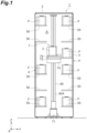
- the stacker crane 7 includes a travel unit 71, a mast 80, an elevation portion 74, a rotation unit 75, a hand 79, a cover unit (covering member)83 and FFU (Fan Filter Unit)96.
- the travel unit 71 is capable of traveling along a rail in X direction by a travel driver such as a motor.
- the elevation portion 74 moves up and down along an elevation surface 80B of the mast 80.
- the mast 80 which is disposed at the travel unit 71 extends in Z direction (a first direction).
- the elevation portion 74 is capable of moving up and down along the mast 80 by an elevation driver such as motor.
- the rotation unit 75 rotates the hand 79 mounted on the rotation unit 75 around an axis along Z direction.
- the hand 79 on which the container F is placed is provided at the elevation portion 74.
- the hand 79 moves in and out (inside and outside the elevation portion 74 in a plan view) to transfer the container F with a transfer device (not illustrated).
- a transfer device not illustrated.
- configurations, mechanisms, and locations of the travel unit 71, the elevation portion 74, the rotation unit 75, and the hand 79 are not specifically limited. Any known mechanisms or devices are adoptable for the travel unit 71, the elevation portion 74, the rotation unit 75, and the hand 79.
- the controller controls components or parts of the stacker crane 7.
- the controller is located, e.g. in the stocker body 3.
- the controller includes CPU (Central Processing Unit) , RAM (Random Access Memory) , and ROM (Read Only Memory) .
- the controller can perform control operations in cooperation between hardware such as CPU, RAM, and ROM, and software such as program.
- the mast 80 includes two channel members 81, 82, a slide rail 87, a back cover 88, and two of an adjusting member 90, 90.
- an elevation surface forming portion 80A, a pair of side surface portions 80C, 80C, and a reinforcement 80D are formed with two channel members 81, 82.
- the elevation surface forming portion 80A includes the elevation surface 80B extending in Z direction and Y direction (a second direction), the elevation surface along which the elevation portion 74 moves up and down.
- the elevation surface 80B is orthogonal to X direction.
- the pair of side surface portions 80C, 80C extend in X direction from both edges of the elevation surface forming portion 80A in Y direction toward an opposite side of a side at which the elevation portion 74 is located.
- the reinforcement portion 80D is arranged between the pair of side surface portions 80C, 80C in Y direction and extends in X direction from a side opposite to the elevation surface 80B of the elevation surface forming portion 80A toward an opposite side of a side at which the elevation portion 74 is located.
- the reinforcement portion 80D is formed so as to have a higher stiffness than that of each of the side surface portions 80C, 80C.
- the elevation surface forming portion 80A, the pair of side surface portions 80C, 80C, and the reinforcement 80D are formed with two channel members 81, 82.
- the channel member 81 includes a web part 81A and a pair of flange portions 81B, 81B extending(erecting) in X direction from both edges of the web part 81A in Y direction.
- the channel member 82 includes a web part 82A and a pair of flange portions 82B, 82B extending (erecting) in X direction from both edges of the web part 82A in Y direction.
- the channel member 81 and the channel member 81 are the same in size and shape.
- the web part 81A and the web part 82A have the same thickness and the flange portion 81B and the flange portion 82B have the same thickness.
- the channel member 81 and the channel member 82 are made of, e.g. a stainless steel which is a low-cost metal with high stiffness.
- the flange portion 81B of the channel member 81 and the flange portion 82B of the channel member 82 are jointed with each other so that the web part 81A of the channel member 81 and the web part 82A of the channel member 82 can be flush.
- the web part 81A of the channel member 81 and the web part 82A of the channel member 82 formed to be flush forms the elevation surface 80B of the mast 80.
- One of the flange portion 81B of the channel member 81 forms the one of the side surface portion 80C of the mast 80 and the other of the flange portion 82B of the channel member 82 forms the other of the side surface portion 80C of the mast 8.
- the reinforcement portion 80D of the mast 80 is formed by a joint between the other of the flange portion 81B of the channel member 81 and the other of the flange portion 81B of the channel member 82.
- a part of the mast which includes the elevation surface forming portion 80A, the pair of side surface portions 80C, 80C, and the reinforcement portion 80D, is formed in an E shape in a plan view seen from Z direction.
- a slide rail 87 extending in Z direction and used for the elevation portion 74 is fixed to the elevation surface 80B of the elevation surface forming portion 80A.
- the cover unit 83 covers an elevation area 80E of the elevation portion 74.
- the cover unit 83 includes two angle members 84, 85 and two of a cover 86, 86.
- the cover unit 83 is attached integrally to each of the pair of side surface portions 80C, 80C with a coupler (not illustrated).
- the angle member 84 is attached integrally to the channel member 81 and the angle member 85 is attached integrally to the channel member 82.
- the angle member 84 and the angle member 85 are made of, e.g. a stainless steel which is a low-cost metal with high stiffness.
- the angle member 84 has a first surface 84A and a second surface 84 B perpendicular to the first surface 84 A.
- the first surface 84A is attached integrally to the flange portion 81B of the channel member 81.
- the cover 86 is attached to a top edge of the second surface 84B.
- the angle member 85 has a first surface 85A and a second surface 85B perpendicular to the first surface 85A.
- the first surface 85A is attached integrally to the flange portion 82B of the channel member 82.
- the cover 86 is attached to a top edge of the second surface 85B.
- the cover 86 is made of a material e.g. an aluminum plate.
- a gap G is formed between a top edge 86A of the cover 86 attached to the angle member 84 and a top edge 86A of the cover 86 attached to the angle member 85 in Y direction.
- the rotation unit 75 and the hand 79 protrudes to an outer space from the elevation portion 74 placed within the 80E through the space G.
- the top edge 86A of the cover 86 is provided so as not to interfere with the elevation portion 74, rotation unit 75, and the hand 79.
- the back cover 88 is provided at back side of the mast 80.
- the back cover 88 is attached to top edges of the pair of flange portions 81B, 81B of the channel member 81 and top edges of the pair of flange portions 82B, 82B of the channel member 82.
- a recessed space 80F is formed with the web part 81A, the pair of flange portions 81B, 81B, and the back cover 88.
- the recessed space 80F is also formed with the web part 82A, the pair of flange portions 82B, 82B, and the back cover 88.
- each of the adjusting member 90 extends in Y direction and is a turnbuckle member stretchable in Y direction.
- the adjusting member 90 is arranged in the recessed space 80F.
- the adjusting member 90 is arranged away from the elevation surface forming portion 80A in X direction (a third direction).
- the adjusting member 90 is arranged in two rows in Y direction.
- One of the adjusting member 90 is provided so that both edges thereof can contact with one of the flange portion 81B forming the reinforcement portion 80D and the other of the flange portion 81B forming the side surface portion 80C, and the other of the adjusting member 90 is provided so that both edges thereof can contact with one of the flange portion 82B forming the reinforcement portion 80D and the other of the flange portion 82B forming the side surface portion 80C.
- a total length of the channel member 81 (82) in X direction is referred to as D and a distance between the adjusting member 90 and the back cover 88 is referred to as D1.
- the adjusting member 90 is provided so that D1 can be equal to or shorter than a half of D (D1 ⁇ 1/2D). Without any back cover 88, the adjusting members 90 may be provided so that top edges of the pair of flange portions 81B, 81B (82B, 82B) can contact with each other.
- the adjusting member 90 includes a body 91A, 91B, a first screw bolt 92A screwing into a thread groove formed at a hole of the body 91A, a second screw bolt 92B screwing into a thread groove formed at a hole of the body 91B, an anchor 93 provided at a top edge of the first screw bolt 92A, and an anchor 94 provided at a top edge of the second screw bolt 92B.
- the anchor 93 (94) is provided with a bolt 93B (94B) to be fixed to the flange portion 81B.
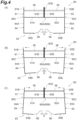
- Two of the adjusting member 90, 90 can adjust an intersection angle ⁇ (see FIG, 2 ) of the pair of side surface portions 80C, 80C with respect to the elevation surface forming portion 80A by rotating the first screw bolt 92A and the second screw bolt 92B screwed by the bodies 91A, 91B, respectively.
- a method of adjusting the intersection angle ⁇ of the pair of the side surface portions 80C, 80C with respect to the elevation surface forming portion 81A will now be described in detail.
- the adjusting member 90 acts so as to push out one of the flange portion 81B and one of the flange portion 82B (corresponding to the side surface portion 80C) in a direction away from the other of the flange portion 81B and the other of the flange portion 82B (corresponding to the reinforcement portion 80D) by rotating a top edge (anchor 93) of the first screw bolt 92A in a direction away from the body 91A and rotating top edge (anchor 94) of the second screw bolt 92B in a direction away from the body 91B.
- a location and a posture of the first surface 84A of the angle member 84 change so as to be flush with one of the flange portion 81B and a location and a posture of the first surface 85A of the angle member 85 change so as to be flush with one of the flange portion 82B, thereby changing the pair of the side surface portions 80C, 80C from a state shown in FIG. 4 (A) to a state shown in FIG. 4(B) .
- the pair of the side surface portions 80C, 80C is deformed such that a back side of the mast 80 opens (moves farther from each other).
- the deformation of the mast 80 changes a location and a posture of the cover unit 83.
- the first screw bolt 92 A and the second screw bolt 92B are adjusted, so that positions and postures of one of the flange portion 81B and one of the flange portion 82B, the first surface 84A and the second surface 84B of the angle member 84, and the first surface 85A and the second surface 85B of the angle member 85 are changed, as a result, the gap G between top edges of two of the cover 86 becomes narrower than its original state.
- the adjusting member 90 acts so as to pull one of the flange portion 81B and one of the flange portion 82B (corresponding to the side surface portion 80C) in an approaching direction to the other of the flange portion 81B and the other of the flange portion 82B (corresponding to the reinforcement portion 80D) by rotating a top edge of the first screw bolt 92A (anchor 93) in an approaching direction to the body 91A and rotating a top edge of the second screw bolt 92B (anchor 94) in an approaching direction to the body 91B.
- a location and a posture of the first surface 84A of the angle member 84 change so as to be flush with one of the flange portion 81B and a location and a posture of the first surface 85A of the angle member 85 change so as to be flush with one of the flange portion 82B, thereby changing the pair of the side surface portions 80C, 80C from the state shown in FIG. 4(A) to a state shown in FIG. 4(C) . Therefore, the pair of the side surface portions 80C, 80C are deformed such that a side of the elevation surface 80B of the mast 80 closes (approaches to each other). The deformation of the mast 80 changes a location and a posture of the cover unit 83.
- the first screw bolt 92A and the second screw bolt 92B are adjusted, so that locations and postures of one of the flange portion 81B, one of the flange portion 82B, the first surface 84A and the second surface 84B of the angle member 84, and the first surface 85A and the second surface 85B of the angle member 85 are changed, as a result, the gap G between top edges of two of the cover 86 becomes wider than its original state.
- the gap G between top edges of two of the cover 86 becomes narrower than its original state by rotating a top edge (anchor 93) of the first screw bolt 92A so as to keep away from the body 91A and rotating top edge (anchor 94) of the second screw bolt 92B so as to keep away from the body 91B, and the gap G between top edges of two of the covers 86 becomes wider than its original state by rotating a top edge (anchor 93) of the first screw bolt 92A so as to keep close to the body 91A and rotating a top edge of the second screw bolt 92B (anchor 94) so as to keep close to the body 91B.
- whether the gap G between the top edges of two of the cover 86 becomes narrower or wider than its original state may depend on a shape of the cover 86 attached to the second surface 84B of the angle member 84 and the second surface 85B of the angle member 85.
- both of top edges of the first screw bolt 92A and the second screw bolt 92B are moved so as to keep away from each of the bodies 91A, 91B or to keep close to each of the bodies 91A, 91B.
- only one of the top edge of the first screw bold 92A and the top edge of the second screw bolt 92B may be moved to keep away from the body 91A or the body 91B or keep close to the body 91A or the body 91B.
- one of the top edge of the first screw bolt 92A and one of the top edge of the second screw bolt 92B may be moved to keep away from the body 91A and the body 91B, or the other of the top edge of the first screw bolt 92A and the other of the top edge of the second screw bolt 92B may be moved to keep close to the body 91A or the body 91B.
- These adjustments of the adjusting member 90 can adjust a relative position of the cover 86 to the elevation portion 74.
- two of the adjusting member 90, 90 have an adjustment function to adjust the intersection angle ⁇ of the pair of side surface portions 80C, 80C with respect to the elevation surface forming portion 80A.
- Two of the adjusting member 90, 90 also has a reinforcement function to reinforce a stiffness of the mast 80 overall.
- Two of the adjusting member 90, 90 is arranged at a predetermined interval in a direction in which the mast 80 extends. The number of adjusting member 90 to be arranged is set appropriately according to ease of deformation of the pair of the side surface portions 80C, 80C of a member comprising the mast 80.
- the FFU 96 is arranged in the recessed space 80F.
- the FFU 96 is arranged in the recessed space 80F formed with the elevation surface forming portion 80A, the side surface portion 80C and the reinforcement portion 80D in a plan view seen from Z direction.
- the FFU 96 is an air cleaning device with fan and filter to draw in ambient air and discharge purified air.
- the adjusting member 90 which is a stretchable member is provided between the side surface portion 80C and the reinforcement portion 80D having a higher stiffness than that of the side surface portion 80C, so that the side surface portion 80C of the mast 80 is pushed out by extension of the adjusting member 90 so as to keep away from the reinforcement portion 80D, and the side surface portion 80C of the mast 80 is pulled by contraction of the adjusting member 90 so as to keep close to the reinforcement portion 80D.
- the intersection angle ⁇ of the side surface portion 80C with respect to the elevation surface forming portion 80A is adjusted by pushing or pulling the side surface portion 80C.
- a position of the cover unit 83 relative to the elevation portion 74 can be adjusted easily, so that the cover 86 can be placed at a marginal position so as not to interfere with the elevation portion 74 which is moving up and down, thus enabling to reduce generation of dusts due to contact between the elevation portion 74 and the cover 86 and to prevent dust generated at the elevation area 80E from flowing into the inner space A of the stocker 1.
- the adjusting member 90 is provided, so that the stiffness of the mast 80 is heightened as a whole. Further, the adjusting member 90 is provided, so that the stiffness of the entire mast 80 can be heightened, thus allowing a total size of the mast 80 to be smaller if the mast 80 has the same performance.
- the mast 80 is formed by connection between the flange portions 81B and 82B of two channel members 81, 82 including the web part 81A (82A) and the pair of flange portions 81B, 81B (82B, 82B) erecting from the both edges of the web part 81A (82A). Therefore, the mast 80 can be formed easily with the elevation surface forming portion 80A, the pair of side surface portions 80C, 80C, and the enforcement portion 80D.
- the cover unit 83 to cover the elevation area 80E of the elevation portion 74 is provided, thus enabling to prevent dusts occurring when the elevation portion 74 moves up and down from spreading out in the inner space A of the stocker 1.
- the FFU 96 is placed in the recessed space 80F formed with the elevation surface forming portion A, the side surface portion 80C, and the reinforcement portion 80D in a plan view seen from Z direction. Therefore, the FFU 96 can be placed between members comprising the mast 80, as a result, allowing a total size of the mast 80 to be compact.
- the mast formed in an E shape in a plan view seen from Z direction is formed by connection between two channel members 81, 82, however, it is not limited to.
- a single member with an E-shaped cross section may be used.
- a member with a C-shaped cross section is integrally welded with a member which functions as the reinforcement portion 80D to form an E shape, which may be used.
- the surfaces of the channel members 81,82 and the angle members 84,85 are formed in a flat plate shape, however, a groove may be formed on each of the surfaces of these members.
Landscapes
- Engineering & Computer Science (AREA)
- Mechanical Engineering (AREA)
- Transportation (AREA)
- Structural Engineering (AREA)
- Civil Engineering (AREA)
- Life Sciences & Earth Sciences (AREA)
- Geology (AREA)
- Warehouses Or Storage Devices (AREA)
- Radiation-Therapy Devices (AREA)
Claims (5)
- Stapelkran (7), umfassend;einen Mast (80) einschließlich einen eine Erhöhungsfläche bildenden Abschnitt (80A) mit einer Erhöhungsfläche (80B), die sich in einer ersten Richtung, in der sich ein Erhöhungsabschnitt (74) nach oben und nach unten bewegt, und in einer zweiten Richtung orthogonal zur ersten Richtung erstreckt, und ein Paar Seitenflächenabschnitte (80C), die sich in einer dritten Richtung orthogonal zur ersten Richtung und zur zweiten Richtung von beiden Rändern des eine Erhöhungsfläche bildenden Abschnitts in der zweiten Richtung zu einer Seite erstrecken, die einer Seite gegenüberliegt, an der der Erhöhungsabschnitt angeordnet ist,das Paar von Seitenflächenabschnitten (80C) so angeordnet ist, dass ein Abdeckelement (83), das einen Erhöhungsbereich (80E) des Erhöhungsabschnitts (74) abdeckt, einstückig an dem Paar von Seitenflächenabschnitten angebracht werden kann, undwobei der Stapelkran (7) dadurch gekennzeichnet ist, dass der Mast einschließt:einen Verstärkungsabschnitt (80D), der zwischen dem Paar von Seitenflächenabschnitten in der zweiten Richtung angeordnet ist, sich in der dritten Richtung von dem eine Erhöhungsfläche bildenden Abschnitt zu der Seite erstreckt, die der Seite, an der der Erhöhungsabschnitt angeordnet ist, gegenüberliegt, und eine höhere Steifigkeit als die des Paars von Seitenflächenabschnitten aufweist; undein Einstellelement (90), das so angeordnet ist, dass in der dritten Richtung ein Spiel mit dem die Erhöhungsfläche bildenden Abschnitt verbleibt, wobei sich das Einstellelement in der zweiten Richtung erstrecken kann, und so bereitgestellt ist, dass beide Ränder mit dem Verstärkungsteil und dem Paar von Seitenflächenabschnitten in Berührung kommen.
- Stapelkran nach Anspruch 1,
wobei ein Teil des Mastes, der durch den die Erhöhungsfläche bildenden Abschnitt, das Paar von Seitenflächenabschnitten und den Verstärkungsabschnitt gebildet wird, in einer Draufsicht aus der ersten Richtung gesehen eine E-Form aufweist. - Stapelkran nach einem der Ansprüche 1 oder 2,
wobei der Mast durch Verbinden eines Paares von Flanschabschnitten (81B) gebildet wird, die von beiden Rändern eines Stegteils abstehen, das auf zwei Kanalelementen bereitgestellt ist. - Stapelkran nach einem der Ansprüche 1 bis 3, weiter umfassend ein Abdeckelement (83), das bereitgestellt ist, um einen Erhöhungsbereich (80E) des Erhöhungsabschnitts zu bedecken, und einstückig mit dem Paar von Seitenflächenabschnitten verbunden ist.
- Stapelkran nach einem der Ansprüche 1 bis 4,
wobei eine Gebläsefiltereinheit (96) in einem ausgesparten Raum (80F) angeordnet ist, der durch den eine Erhöhungsfläche bildenden Abschnitt, das Paar von Seitenflächenabschnitten und den Verstärkungsabschnitt in einer Draufsicht aus der ersten Richtung gesehen gebildet wird.
Applications Claiming Priority (2)
| Application Number | Priority Date | Filing Date | Title |
|---|---|---|---|
| JP2019212415A JP2022191535A (ja) | 2019-11-25 | 2019-11-25 | スタッカクレーン |
| PCT/JP2020/037613 WO2021106374A1 (ja) | 2019-11-25 | 2020-10-02 | スタッカクレーン |
Publications (3)
| Publication Number | Publication Date |
|---|---|
| EP4046942A1 EP4046942A1 (de) | 2022-08-24 |
| EP4046942A4 EP4046942A4 (de) | 2023-11-29 |
| EP4046942B1 true EP4046942B1 (de) | 2024-11-27 |
Family
ID=76130463
Family Applications (1)
| Application Number | Title | Priority Date | Filing Date |
|---|---|---|---|
| EP20892755.8A Active EP4046942B1 (de) | 2019-11-25 | 2020-10-02 | Stapelkran |
Country Status (7)
| Country | Link |
|---|---|
| US (1) | US12030759B2 (de) |
| EP (1) | EP4046942B1 (de) |
| JP (1) | JP2022191535A (de) |
| CN (1) | CN114728745B (de) |
| IL (1) | IL293043B2 (de) |
| TW (1) | TWI848187B (de) |
| WO (1) | WO2021106374A1 (de) |
Families Citing this family (1)
| Publication number | Priority date | Publication date | Assignee | Title |
|---|---|---|---|---|
| JP7516182B2 (ja) | 2020-09-17 | 2024-07-16 | 古河電気工業株式会社 | 光ファイバの製造方法および装置 |
Family Cites Families (19)
| Publication number | Priority date | Publication date | Assignee | Title |
|---|---|---|---|---|
| JPH04350007A (ja) * | 1991-02-12 | 1992-12-04 | Murata Mach Ltd | クリーン倉庫内で使用される物品搬入搬出装置 |
| JP3067528B2 (ja) * | 1994-06-20 | 2000-07-17 | 株式会社ダイフク | 荷保管設備 |
| JP3267932B2 (ja) * | 1998-05-20 | 2002-03-25 | 村田機械株式会社 | 搬送装置 |
| JP2000016518A (ja) * | 1998-06-26 | 2000-01-18 | Murata Mach Ltd | 自動倉庫 |
| JP2000044012A (ja) * | 1998-07-28 | 2000-02-15 | Toyota Autom Loom Works Ltd | スタッカクレーン及び自動倉庫 |
| JP3835377B2 (ja) * | 2001-11-28 | 2006-10-18 | 村田機械株式会社 | スタッカークレーン |
| JP2004091157A (ja) * | 2002-08-30 | 2004-03-25 | Murata Mach Ltd | 搬送装置 |
| JP3982562B1 (ja) * | 2006-09-28 | 2007-09-26 | 株式会社Ihi | スタッカクレーン |
| JP2008114969A (ja) * | 2006-11-02 | 2008-05-22 | Hitachi Plant Technologies Ltd | スタッカクレーンのマスト内浄化装置 |
| JP4415397B2 (ja) * | 2007-09-03 | 2010-02-17 | 村田機械株式会社 | スタッカークレーン |
| JP4688000B2 (ja) * | 2008-02-06 | 2011-05-25 | 株式会社ダイフク | 物品収納設備 |
| JP5422908B2 (ja) * | 2008-04-15 | 2014-02-19 | 株式会社Ihi | 昇降台車 |
| JP2013216446A (ja) * | 2012-04-09 | 2013-10-24 | Daifuku Co Ltd | 清掃装置 |
| US9809433B2 (en) * | 2013-05-16 | 2017-11-07 | Murata Machinery, Ltd. | Stacker crane |
| JP6220197B2 (ja) * | 2013-09-09 | 2017-10-25 | 川崎重工業株式会社 | ロボット |
| JP6201977B2 (ja) * | 2014-12-19 | 2017-09-27 | 村田機械株式会社 | 自動倉庫及びその運転方法 |
| JP6726404B2 (ja) * | 2016-09-26 | 2020-07-22 | 株式会社ダイフク | ラックの側枠構造体 |
| JP6766878B2 (ja) * | 2016-10-18 | 2020-10-14 | 村田機械株式会社 | スタッカクレーン |
| TW202249142A (zh) * | 2021-02-25 | 2022-12-16 | 日商東京威力科創股份有限公司 | 基板搬送機構及基板搬送方法 |
-
2019
- 2019-11-25 JP JP2019212415A patent/JP2022191535A/ja active Pending
-
2020
- 2020-10-02 CN CN202080081060.4A patent/CN114728745B/zh active Active
- 2020-10-02 EP EP20892755.8A patent/EP4046942B1/de active Active
- 2020-10-02 IL IL293043A patent/IL293043B2/en unknown
- 2020-10-02 US US17/778,615 patent/US12030759B2/en active Active
- 2020-10-02 WO PCT/JP2020/037613 patent/WO2021106374A1/ja not_active Ceased
- 2020-11-24 TW TW109141070A patent/TWI848187B/zh active
Also Published As
| Publication number | Publication date |
|---|---|
| CN114728745B (zh) | 2023-12-01 |
| TWI848187B (zh) | 2024-07-11 |
| IL293043B2 (en) | 2025-02-01 |
| US20230002206A1 (en) | 2023-01-05 |
| CN114728745A (zh) | 2022-07-08 |
| WO2021106374A1 (ja) | 2021-06-03 |
| US12030759B2 (en) | 2024-07-09 |
| EP4046942A4 (de) | 2023-11-29 |
| JP2022191535A (ja) | 2022-12-28 |
| IL293043A (en) | 2022-07-01 |
| IL293043B1 (en) | 2024-10-01 |
| TW202134147A (zh) | 2021-09-16 |
| EP4046942A1 (de) | 2022-08-24 |
Similar Documents
| Publication | Publication Date | Title |
|---|---|---|
| JP5853991B2 (ja) | 基板搬送ロボット、基板搬送システムおよび基板搬送方法 | |
| US10283394B2 (en) | Article transport device | |
| JP5267725B2 (ja) | 基板搬送システム、基板処理システムおよび基板搬送ロボット | |
| US10081494B2 (en) | Container transport device and container transport facility | |
| JP5553065B2 (ja) | 基板搬送用ハンドおよび基板搬送ロボット | |
| US10766697B2 (en) | Storage rack and article storage facility | |
| US10287096B2 (en) | Article support rack | |
| EP4046942A1 (de) | Stapelkran | |
| US12103772B2 (en) | Wafer storage system | |
| JP2022035763A (ja) | 基板を搬送する装置、基板を処理するシステム、及び基板を処理する方法 | |
| US20130028688A1 (en) | Load port apparatus and clamping device to be used for the same | |
| US20240174442A1 (en) | Article Storage Shelf | |
| TWI889064B (zh) | 具有多層設備前端模組的基板移送裝置 | |
| US20090236261A1 (en) | Electronic component accommodating device | |
| KR102778943B1 (ko) | 로드 포트 및 efem | |
| JP6477579B2 (ja) | 容器支持棚 | |
| JP7662388B2 (ja) | 基板搬送ロボットおよび基板搬送装置 | |
| KR20250009334A (ko) | 상단 개방형 기판 컨테이너용 고정 장치 | |
| KR20080062166A (ko) | 랙마스터 및 그 운용방법 |
Legal Events
| Date | Code | Title | Description |
|---|---|---|---|
| STAA | Information on the status of an ep patent application or granted ep patent |
Free format text: STATUS: THE INTERNATIONAL PUBLICATION HAS BEEN MADE |
|
| PUAI | Public reference made under article 153(3) epc to a published international application that has entered the european phase |
Free format text: ORIGINAL CODE: 0009012 |
|
| STAA | Information on the status of an ep patent application or granted ep patent |
Free format text: STATUS: REQUEST FOR EXAMINATION WAS MADE |
|
| 17P | Request for examination filed |
Effective date: 20220519 |
|
| AK | Designated contracting states |
Kind code of ref document: A1 Designated state(s): AL AT BE BG CH CY CZ DE DK EE ES FI FR GB GR HR HU IE IS IT LI LT LU LV MC MK MT NL NO PL PT RO RS SE SI SK SM TR |
|
| DAV | Request for validation of the european patent (deleted) | ||
| DAX | Request for extension of the european patent (deleted) | ||
| A4 | Supplementary search report drawn up and despatched |
Effective date: 20231027 |
|
| RIC1 | Information provided on ipc code assigned before grant |
Ipc: H01L 21/677 20060101ALI20231023BHEP Ipc: B65G 1/04 20060101AFI20231023BHEP |
|
| GRAP | Despatch of communication of intention to grant a patent |
Free format text: ORIGINAL CODE: EPIDOSNIGR1 |
|
| STAA | Information on the status of an ep patent application or granted ep patent |
Free format text: STATUS: GRANT OF PATENT IS INTENDED |
|
| INTG | Intention to grant announced |
Effective date: 20240702 |
|
| GRAS | Grant fee paid |
Free format text: ORIGINAL CODE: EPIDOSNIGR3 |
|
| GRAA | (expected) grant |
Free format text: ORIGINAL CODE: 0009210 |
|
| STAA | Information on the status of an ep patent application or granted ep patent |
Free format text: STATUS: THE PATENT HAS BEEN GRANTED |
|
| AK | Designated contracting states |
Kind code of ref document: B1 Designated state(s): AL AT BE BG CH CY CZ DE DK EE ES FI FR GB GR HR HU IE IS IT LI LT LU LV MC MK MT NL NO PL PT RO RS SE SI SK SM TR |
|
| REG | Reference to a national code |
Ref country code: GB Ref legal event code: FG4D |
|
| REG | Reference to a national code |
Ref country code: CH Ref legal event code: EP |
|
| REG | Reference to a national code |
Ref country code: IE Ref legal event code: FG4D |
|
| REG | Reference to a national code |
Ref country code: DE Ref legal event code: R096 Ref document number: 602020042280 Country of ref document: DE |
|
| REG | Reference to a national code |
Ref country code: LT Ref legal event code: MG9D |
|
| REG | Reference to a national code |
Ref country code: NL Ref legal event code: MP Effective date: 20241127 |
|
| PG25 | Lapsed in a contracting state [announced via postgrant information from national office to epo] |
Ref country code: PT Free format text: LAPSE BECAUSE OF FAILURE TO SUBMIT A TRANSLATION OF THE DESCRIPTION OR TO PAY THE FEE WITHIN THE PRESCRIBED TIME-LIMIT Effective date: 20250327 Ref country code: IS Free format text: LAPSE BECAUSE OF FAILURE TO SUBMIT A TRANSLATION OF THE DESCRIPTION OR TO PAY THE FEE WITHIN THE PRESCRIBED TIME-LIMIT Effective date: 20250327 Ref country code: HR Free format text: LAPSE BECAUSE OF FAILURE TO SUBMIT A TRANSLATION OF THE DESCRIPTION OR TO PAY THE FEE WITHIN THE PRESCRIBED TIME-LIMIT Effective date: 20241127 |
|
| PG25 | Lapsed in a contracting state [announced via postgrant information from national office to epo] |
Ref country code: FI Free format text: LAPSE BECAUSE OF FAILURE TO SUBMIT A TRANSLATION OF THE DESCRIPTION OR TO PAY THE FEE WITHIN THE PRESCRIBED TIME-LIMIT Effective date: 20241127 Ref country code: NL Free format text: LAPSE BECAUSE OF FAILURE TO SUBMIT A TRANSLATION OF THE DESCRIPTION OR TO PAY THE FEE WITHIN THE PRESCRIBED TIME-LIMIT Effective date: 20241127 |
|
| REG | Reference to a national code |
Ref country code: AT Ref legal event code: MK05 Ref document number: 1745530 Country of ref document: AT Kind code of ref document: T Effective date: 20241127 |
|
| PG25 | Lapsed in a contracting state [announced via postgrant information from national office to epo] |
Ref country code: BG Free format text: LAPSE BECAUSE OF FAILURE TO SUBMIT A TRANSLATION OF THE DESCRIPTION OR TO PAY THE FEE WITHIN THE PRESCRIBED TIME-LIMIT Effective date: 20241127 |
|
| PG25 | Lapsed in a contracting state [announced via postgrant information from national office to epo] |
Ref country code: ES Free format text: LAPSE BECAUSE OF FAILURE TO SUBMIT A TRANSLATION OF THE DESCRIPTION OR TO PAY THE FEE WITHIN THE PRESCRIBED TIME-LIMIT Effective date: 20241127 |
|
| PG25 | Lapsed in a contracting state [announced via postgrant information from national office to epo] |
Ref country code: NO Free format text: LAPSE BECAUSE OF FAILURE TO SUBMIT A TRANSLATION OF THE DESCRIPTION OR TO PAY THE FEE WITHIN THE PRESCRIBED TIME-LIMIT Effective date: 20250227 |
|
| PG25 | Lapsed in a contracting state [announced via postgrant information from national office to epo] |
Ref country code: LV Free format text: LAPSE BECAUSE OF FAILURE TO SUBMIT A TRANSLATION OF THE DESCRIPTION OR TO PAY THE FEE WITHIN THE PRESCRIBED TIME-LIMIT Effective date: 20241127 Ref country code: AT Free format text: LAPSE BECAUSE OF FAILURE TO SUBMIT A TRANSLATION OF THE DESCRIPTION OR TO PAY THE FEE WITHIN THE PRESCRIBED TIME-LIMIT Effective date: 20241127 Ref country code: GR Free format text: LAPSE BECAUSE OF FAILURE TO SUBMIT A TRANSLATION OF THE DESCRIPTION OR TO PAY THE FEE WITHIN THE PRESCRIBED TIME-LIMIT Effective date: 20250228 |
|
| PG25 | Lapsed in a contracting state [announced via postgrant information from national office to epo] |
Ref country code: PL Free format text: LAPSE BECAUSE OF FAILURE TO SUBMIT A TRANSLATION OF THE DESCRIPTION OR TO PAY THE FEE WITHIN THE PRESCRIBED TIME-LIMIT Effective date: 20241127 |
|
| PG25 | Lapsed in a contracting state [announced via postgrant information from national office to epo] |
Ref country code: RS Free format text: LAPSE BECAUSE OF FAILURE TO SUBMIT A TRANSLATION OF THE DESCRIPTION OR TO PAY THE FEE WITHIN THE PRESCRIBED TIME-LIMIT Effective date: 20250227 |
|
| PG25 | Lapsed in a contracting state [announced via postgrant information from national office to epo] |
Ref country code: SM Free format text: LAPSE BECAUSE OF FAILURE TO SUBMIT A TRANSLATION OF THE DESCRIPTION OR TO PAY THE FEE WITHIN THE PRESCRIBED TIME-LIMIT Effective date: 20241127 |
|
| PG25 | Lapsed in a contracting state [announced via postgrant information from national office to epo] |
Ref country code: DK Free format text: LAPSE BECAUSE OF FAILURE TO SUBMIT A TRANSLATION OF THE DESCRIPTION OR TO PAY THE FEE WITHIN THE PRESCRIBED TIME-LIMIT Effective date: 20241127 |
|
| PG25 | Lapsed in a contracting state [announced via postgrant information from national office to epo] |
Ref country code: EE Free format text: LAPSE BECAUSE OF FAILURE TO SUBMIT A TRANSLATION OF THE DESCRIPTION OR TO PAY THE FEE WITHIN THE PRESCRIBED TIME-LIMIT Effective date: 20241127 |
|
| PG25 | Lapsed in a contracting state [announced via postgrant information from national office to epo] |
Ref country code: RO Free format text: LAPSE BECAUSE OF FAILURE TO SUBMIT A TRANSLATION OF THE DESCRIPTION OR TO PAY THE FEE WITHIN THE PRESCRIBED TIME-LIMIT Effective date: 20241127 |
|
| PG25 | Lapsed in a contracting state [announced via postgrant information from national office to epo] |
Ref country code: SK Free format text: LAPSE BECAUSE OF FAILURE TO SUBMIT A TRANSLATION OF THE DESCRIPTION OR TO PAY THE FEE WITHIN THE PRESCRIBED TIME-LIMIT Effective date: 20241127 |
|
| PG25 | Lapsed in a contracting state [announced via postgrant information from national office to epo] |
Ref country code: CZ Free format text: LAPSE BECAUSE OF FAILURE TO SUBMIT A TRANSLATION OF THE DESCRIPTION OR TO PAY THE FEE WITHIN THE PRESCRIBED TIME-LIMIT Effective date: 20241127 |
|
| PG25 | Lapsed in a contracting state [announced via postgrant information from national office to epo] |
Ref country code: IT Free format text: LAPSE BECAUSE OF FAILURE TO SUBMIT A TRANSLATION OF THE DESCRIPTION OR TO PAY THE FEE WITHIN THE PRESCRIBED TIME-LIMIT Effective date: 20241127 |
|
| REG | Reference to a national code |
Ref country code: DE Ref legal event code: R097 Ref document number: 602020042280 Country of ref document: DE |
|
| PG25 | Lapsed in a contracting state [announced via postgrant information from national office to epo] |
Ref country code: SE Free format text: LAPSE BECAUSE OF FAILURE TO SUBMIT A TRANSLATION OF THE DESCRIPTION OR TO PAY THE FEE WITHIN THE PRESCRIBED TIME-LIMIT Effective date: 20241127 |
|
| PLBE | No opposition filed within time limit |
Free format text: ORIGINAL CODE: 0009261 |
|
| STAA | Information on the status of an ep patent application or granted ep patent |
Free format text: STATUS: NO OPPOSITION FILED WITHIN TIME LIMIT |
|
| PGFP | Annual fee paid to national office [announced via postgrant information from national office to epo] |
Ref country code: IE Payment date: 20250925 Year of fee payment: 6 |
|
| 26N | No opposition filed |
Effective date: 20250828 |
|
| PGFP | Annual fee paid to national office [announced via postgrant information from national office to epo] |
Ref country code: DE Payment date: 20250923 Year of fee payment: 6 |