EP4045778B1 - Anordnung zur thermischen verwaltung eines fahrzeugs - Google Patents
Anordnung zur thermischen verwaltung eines fahrzeugs Download PDFInfo
- Publication number
- EP4045778B1 EP4045778B1 EP20785840.8A EP20785840A EP4045778B1 EP 4045778 B1 EP4045778 B1 EP 4045778B1 EP 20785840 A EP20785840 A EP 20785840A EP 4045778 B1 EP4045778 B1 EP 4045778B1
- Authority
- EP
- European Patent Office
- Prior art keywords
- outlet
- command
- group
- duct
- thermal management
- Prior art date
- Legal status (The legal status is an assumption and is not a legal conclusion. Google has not performed a legal analysis and makes no representation as to the accuracy of the status listed.)
- Active
Links
Images


Classifications
-
- F—MECHANICAL ENGINEERING; LIGHTING; HEATING; WEAPONS; BLASTING
- F01—MACHINES OR ENGINES IN GENERAL; ENGINE PLANTS IN GENERAL; STEAM ENGINES
- F01P—COOLING OF MACHINES OR ENGINES IN GENERAL; COOLING OF INTERNAL-COMBUSTION ENGINES
- F01P7/00—Controlling of coolant flow
- F01P7/14—Controlling of coolant flow the coolant being liquid
- F01P7/16—Controlling of coolant flow the coolant being liquid by thermostatic control
- F01P7/165—Controlling of coolant flow the coolant being liquid by thermostatic control characterised by systems with two or more loops
-
- B—PERFORMING OPERATIONS; TRANSPORTING
- B60—VEHICLES IN GENERAL
- B60K—ARRANGEMENT OR MOUNTING OF PROPULSION UNITS OR OF TRANSMISSIONS IN VEHICLES; ARRANGEMENT OR MOUNTING OF PLURAL DIVERSE PRIME-MOVERS IN VEHICLES; AUXILIARY DRIVES FOR VEHICLES; INSTRUMENTATION OR DASHBOARDS FOR VEHICLES; ARRANGEMENTS IN CONNECTION WITH COOLING, AIR INTAKE, GAS EXHAUST OR FUEL SUPPLY OF PROPULSION UNITS IN VEHICLES
- B60K11/00—Arrangement in connection with cooling of propulsion units
- B60K11/02—Arrangement in connection with cooling of propulsion units with liquid cooling
-
- B—PERFORMING OPERATIONS; TRANSPORTING
- B60—VEHICLES IN GENERAL
- B60K—ARRANGEMENT OR MOUNTING OF PROPULSION UNITS OR OF TRANSMISSIONS IN VEHICLES; ARRANGEMENT OR MOUNTING OF PLURAL DIVERSE PRIME-MOVERS IN VEHICLES; AUXILIARY DRIVES FOR VEHICLES; INSTRUMENTATION OR DASHBOARDS FOR VEHICLES; ARRANGEMENTS IN CONNECTION WITH COOLING, AIR INTAKE, GAS EXHAUST OR FUEL SUPPLY OF PROPULSION UNITS IN VEHICLES
- B60K6/00—Arrangement or mounting of plural diverse prime-movers for mutual or common propulsion, e.g. hybrid propulsion systems comprising electric motors and internal combustion engines
- B60K6/20—Arrangement or mounting of plural diverse prime-movers for mutual or common propulsion, e.g. hybrid propulsion systems comprising electric motors and internal combustion engines the prime-movers consisting of electric motors and internal combustion engines, e.g. HEVs
- B60K6/22—Arrangement or mounting of plural diverse prime-movers for mutual or common propulsion, e.g. hybrid propulsion systems comprising electric motors and internal combustion engines the prime-movers consisting of electric motors and internal combustion engines, e.g. HEVs characterised by apparatus, components or means specially adapted for HEVs
- B60K6/26—Arrangement or mounting of plural diverse prime-movers for mutual or common propulsion, e.g. hybrid propulsion systems comprising electric motors and internal combustion engines the prime-movers consisting of electric motors and internal combustion engines, e.g. HEVs characterised by apparatus, components or means specially adapted for HEVs characterised by the motors or the generators
-
- B—PERFORMING OPERATIONS; TRANSPORTING
- B60—VEHICLES IN GENERAL
- B60K—ARRANGEMENT OR MOUNTING OF PROPULSION UNITS OR OF TRANSMISSIONS IN VEHICLES; ARRANGEMENT OR MOUNTING OF PLURAL DIVERSE PRIME-MOVERS IN VEHICLES; AUXILIARY DRIVES FOR VEHICLES; INSTRUMENTATION OR DASHBOARDS FOR VEHICLES; ARRANGEMENTS IN CONNECTION WITH COOLING, AIR INTAKE, GAS EXHAUST OR FUEL SUPPLY OF PROPULSION UNITS IN VEHICLES
- B60K6/00—Arrangement or mounting of plural diverse prime-movers for mutual or common propulsion, e.g. hybrid propulsion systems comprising electric motors and internal combustion engines
- B60K6/20—Arrangement or mounting of plural diverse prime-movers for mutual or common propulsion, e.g. hybrid propulsion systems comprising electric motors and internal combustion engines the prime-movers consisting of electric motors and internal combustion engines, e.g. HEVs
- B60K6/22—Arrangement or mounting of plural diverse prime-movers for mutual or common propulsion, e.g. hybrid propulsion systems comprising electric motors and internal combustion engines the prime-movers consisting of electric motors and internal combustion engines, e.g. HEVs characterised by apparatus, components or means specially adapted for HEVs
- B60K6/28—Arrangement or mounting of plural diverse prime-movers for mutual or common propulsion, e.g. hybrid propulsion systems comprising electric motors and internal combustion engines the prime-movers consisting of electric motors and internal combustion engines, e.g. HEVs characterised by apparatus, components or means specially adapted for HEVs characterised by the electric energy storing means, e.g. batteries or capacitors
-
- B—PERFORMING OPERATIONS; TRANSPORTING
- B60—VEHICLES IN GENERAL
- B60L—PROPULSION OF ELECTRICALLY-PROPELLED VEHICLES; SUPPLYING ELECTRIC POWER FOR AUXILIARY EQUIPMENT OF ELECTRICALLY-PROPELLED VEHICLES; ELECTRODYNAMIC BRAKE SYSTEMS FOR VEHICLES IN GENERAL; MAGNETIC SUSPENSION OR LEVITATION FOR VEHICLES; MONITORING OPERATING VARIABLES OF ELECTRICALLY-PROPELLED VEHICLES; ELECTRIC SAFETY DEVICES FOR ELECTRICALLY-PROPELLED VEHICLES
- B60L58/00—Methods or circuit arrangements for monitoring or controlling batteries or fuel cells, specially adapted for electric vehicles
- B60L58/10—Methods or circuit arrangements for monitoring or controlling batteries or fuel cells, specially adapted for electric vehicles for monitoring or controlling batteries
- B60L58/24—Methods or circuit arrangements for monitoring or controlling batteries or fuel cells, specially adapted for electric vehicles for monitoring or controlling batteries for controlling the temperature of batteries
-
- F—MECHANICAL ENGINEERING; LIGHTING; HEATING; WEAPONS; BLASTING
- F01—MACHINES OR ENGINES IN GENERAL; ENGINE PLANTS IN GENERAL; STEAM ENGINES
- F01P—COOLING OF MACHINES OR ENGINES IN GENERAL; COOLING OF INTERNAL-COMBUSTION ENGINES
- F01P3/00—Liquid cooling
- F01P3/20—Cooling circuits not specific to a single part of engine or machine
-
- F—MECHANICAL ENGINEERING; LIGHTING; HEATING; WEAPONS; BLASTING
- F01—MACHINES OR ENGINES IN GENERAL; ENGINE PLANTS IN GENERAL; STEAM ENGINES
- F01P—COOLING OF MACHINES OR ENGINES IN GENERAL; COOLING OF INTERNAL-COMBUSTION ENGINES
- F01P5/00—Pumping cooling-air or liquid coolants
- F01P5/10—Pumping liquid coolant; Arrangements of coolant pumps
- F01P2005/105—Using two or more pumps
-
- F—MECHANICAL ENGINEERING; LIGHTING; HEATING; WEAPONS; BLASTING
- F01—MACHINES OR ENGINES IN GENERAL; ENGINE PLANTS IN GENERAL; STEAM ENGINES
- F01P—COOLING OF MACHINES OR ENGINES IN GENERAL; COOLING OF INTERNAL-COMBUSTION ENGINES
- F01P2050/00—Applications
- F01P2050/24—Hybrid vehicles
-
- F—MECHANICAL ENGINEERING; LIGHTING; HEATING; WEAPONS; BLASTING
- F04—POSITIVE - DISPLACEMENT MACHINES FOR LIQUIDS; PUMPS FOR LIQUIDS OR ELASTIC FLUIDS
- F04D—NON-POSITIVE-DISPLACEMENT PUMPS
- F04D13/00—Pumping installations or systems
- F04D13/12—Combinations of two or more pumps
Definitions
- the present invention relates to a thermal management assembly of a thermal regulation system of a vehicle.
- the thermal regulation system of a vehicle which comprises said thermal management assembly.
- the vehicle comprising said system and said thermal management assembly.
- the present invention refers to the automotive sector and in detail to the thermal regulation system of a vehicle.
- vehicle refers to any transport means without any limitation linked to the type or size, i.e., a motor vehicle or a tractor trailer.
- operating group means a specific component or group of components for the execution of a specific operation necessary for the motion of the vehicle. Therefore, for example, operating group means the endothermic motor group, or the battery group, or the gearbox group, or the transmission group or the electric motor group for managing the battery group.
- hybrid-powered vehicle solutions have proliferated, in which there are necessarily a plurality of operating groups such as the endothermic motor group, the battery group and the electric motor group connected to said battery group, in which each operating group has different needs from the other.
- each of said operating groups has different operating behaviors, both during the motion of the vehicle and in parking phases (for example, the electric motor operates in situations with the endothermic motor in standby). It is therefore evident that each operating group requires thermal management, cooling and/or heating, different with respect to the different operating situations of the vehicle.
- Vehicle solutions which comprise for each operating group a specific thermal regulation system, in which a specific amount of working fluid circulates.
- each specific thermal regulation system is designed in its own, requiring specific components (for example specific pump groups).
- the object of the present invention is therefore to provide a new thermal management assembly by which such need is satisfied.
- Such object is achieved by means of a thermal management assembly in accordance with what is claimed in claim 1. Similarly, such object is achieved by means of a thermal regulation system of a vehicle, which comprises such a thermal management assembly as claimed in claim 15. Furthermore, such object is achieved by a vehicle, which comprises the thermal regulation system according to claim 16.
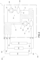
- the reference numeral 1 indicates a thermal management assembly of a thermal regulation system 500 of a vehicle 900, in accordance with the present invention.
- the object of the present invention is also the thermal regulation system 500, which comprises the thermal management assembly 1.
- vehicle 900 comprising the thermal regulation system 500.
- vehicle 900 is hybrid-powered, i.e., it combines both the power supply of an electric motor group and the power supply of a battery group.
- the vehicle 900 comprises a first operating group 910, a second operating group 920 and a third operating group 930.
- Each operating group corresponds to a "load”.
- each operating group corresponds to a respective component or group of components comprised in the vehicle 900 and preferably forming part of the power supply of the vehicle 900.
- the first operating group 910 is an electric motor group.
- the second operating group 920 is a battery group.
- the third operating group 930 is an endothermic motor group.
- the first operating group 910, the second operating group 920 and the third operating group 930 are fluidically in connection with the thermal regulation system 500.
- the first operating group 910, the second operating group 920 and the third operating group 930 are fluidically connected by means of a plurality of system ducts 501, 502, 503, 551, 552, 553 comprised in the thermal regulation system 500.
- specific heat exchanger units (not shown) are also comprised in the thermal regulation system 500.
- the thermal regulation system 500 comprises at least one system inlet duct and at least one system outlet duct in fluidic connection with each operating group.
- the thermal management assembly 1 comprises a first pump group 10 suitable to command the movement of the working fluid comprising a first inlet duct 11 and a first outlet duct 12.
- the thermal management assembly 1 comprises a second pump group 20 suitable, in turn, to command the movement of the working fluid comprising a second inlet duct 21 and a second outlet duct 22.
- the first pump group 10 comprises a first command unit 100 comprising a first impeller, which intercepts working fluid flowing in the first inlet duct 11 to send it into the first outlet duct 12.
- said first impeller is of the radial type, axially aspirating working fluid through the first inlet duct 11 to push it out tangentially towards the first outlet duct 12.
- the first pump group 10 further comprises a first stabilization tank 150, which divides the first inlet duct 11 into a section upstream of the first duct 11' and a section downstream of the first duct 11".
- said first stabilization tank 150 uniforms the pressure of the flowing liquid before it reaches the first impeller comprised in the first command unit 100.
- the working fluid reaches the first command unit 100 after having flowed into the first stabilization tank 150.
- the second pump group 20 comprises a second command unit 200 comprising a second impeller, which intercepts working fluid flowing in the second inlet duct 21 to send it into the second outlet duct 22.
- said second impeller is of the radial type, axially aspirating working fluid through the second inlet duct 21 to push it out tangentially towards the second outlet duct 22.
- the second pump group 20 further comprises a second stabilization tank 250, which divides the second inlet duct 21 into a section upstream of the second duct 21' and a section downstream of a second duct 21".
- said second stabilization tank 250 uniforms the pressure of the flowing liquid before it reaches the second impeller comprised in the second command unit 200.
- the working fluid reaches the second command unit 200 after having flowed into the second stabilization tank 250.
- the thermal management assembly 1 comprises a single stabilization tank fluidically connected both with the first pump group 10 and with the second pump group 20.
- the thermal management assembly 1 further comprises an auxiliary duct 30, which fluidically connects the first pump group 10 and the second pump group 20.
- the auxiliary duct 30 fluidically connects the first outlet duct 12 with the second inlet duct 21.
- the auxiliary duct 30 fluidically connects the first outlet duct 12 with the second inlet duct 21, upstream of the second stabilization tank 250, i.e., preferably in the section upstream of the second duct 21'.
- the first pump group 10 and the second pump group 20 are fluidically arranged in series.
- the thermal management assembly 1 further comprises a first inlet I1 and a second inlet I2 respectively fluidically connected with the first inlet duct 11 and with the second inlet duct 21.
- said first inlet I1 and said second inlet I2 are fluidically connectable with the first operating group 910, with the second operating group 920 and with the third operating group 930.
- the first inlet I1 and said second inlet I2 are fluidically connectable with the system outlet ducts 551, 552, 553 comprised in the thermal regulation system 500.
- At least two system outlet ducts 551, 552, 553 are fluidically connected upstream of the first inlet I1 or of the second inlet I2 so that the working fluid flows into the same outlet upstream thereof.
- the thermal management assembly 1 further comprises other system inlets fluidically connectable with the system ducts.
- the thermal management assembly 1 further comprises a first outlet 01, a second outlet O2 and a third outlet O3.
- Said first outlet O1, said second outlet 02 and said third outlet O3 are fluidically connected with the first outlet duct 12 and with the second outlet duct 22.
- said first outlet O1, said second outlet O2 and said third outlet O3 are respectively fluidically connectable with the first operating group 910, with the second operating group 920 and with the third operating group 930.
- the thermal regulation system 500 installed in the vehicle 900, the working fluid exiting one of the three outlets flows towards a respective operating group.
- the thermal management assembly 1 further comprises a fluidic command device 40 suitable to command the direction of predefined amounts of working fluid in flow in the thermal management assembly 1.
- the fluidic command device 40 is suitable to manage the flow modalities of the working fluid towards an outlet (preventing the flow towards the others) or towards more than one outlet at the same time.
- the fluidic command device 40 is fluidically connected with the first pair of ducts 11, 12 with the second pair of ducts 21, 22 and with the auxiliary duct 30. In this manner, the fluidic command device 40 is suitable to manage in which of these ducts the working fluid flows.
- the fluidic command device 40 is suitable to be fluidically connectable with the described pump groups and with the described operating groups.
- the fluidic command device 40 comprises the first outlet O1, a second outlet O2 and a third outlet O3.
- the fluidic command device 40 is fluidically connected with the first outlet duct 12 and with the second outlet duct 22.
- the fluidic command device 40 is also fluidically connected with the first inlet duct 11 and/or with the second inlet duct 21.
- the fluidic command device 40 is fluidically connected with the auxiliary duct 30.
- the fluidic command device 40 is configurable in:
- the first working configuration is diagrammatically shown, by way of example, in figure 4' .
- the fluidic command device 40 is configured so as to have two fluidic circuits separated from each other, respectively suitable to supply working fluid to the first operating group 910 and to the second operating group 920.
- the second working configuration is diagrammatically shown, by way of example, in figure 4 ".
- the fluidic command device 40 is configured so as to have the two pump groups 10, 20 operating in parallel to supply working fluid to the third operating group 930 only.
- the third working configuration is diagrammatically shown, by way of example, in figure 4 ′′′.
- the fluidic command device 40 is configured so as to have the two pump groups 10, 20 operating in series with each other to supply working fluid to the second operating group 920 only.
- the fluidic command device 40 comprises a plurality of command valve elements 410, 420, 430, 440 fluidically positioned transversely to a respective duct.
- each working configuration corresponds to the adjustment of each command valve element 410, 420, 430, 440 in a predefined position.
- the fluidic command device 40 comprises a command valve element 410, 420, 430, 440 at a respective duct, or at several ducts fluidically connected by the fluidic command device 40, or at two duct sections separated from each other by the fluidic command device 40.
- each command valve element 410, 420, 430, 440 is therefore fluidically connected with a respective inlet hole and a respective outlet hole for the fluidic connection.
- some command valve elements are fluidically connected with more than one inlet and more than one outlet.
- Said inlet holes and outlet holes are, as shown in the attached figures, comprised in the fluidic command device 40 itself, for example in the device body 46 described below.
- each command valve element 410, 420, 430, 440 comprises a command axis X1-X1, X2-X2, X3-X3, X4-X4 with respect to which it is adjustable.
- each command valve element 410, 420, 430, 440 is adjustable in a different angular position with respect to each respective command axis.
- each command valve element 410, 420, 430, 440 is positionable in a preferred angular position, in which it commands the passage of the respective amount of working liquid towards a respective outlet O1, O2, O3.
- each command valve element 410, 420, 430, 440 has an internal command section 410', 420', 430', 440' through which the working fluid flows and as a function of the angular position of the command valve element 410, 420, 430, 440 allows or inhibits the fluidic communication between at least one inlet opening with at least one outlet opening (mutually, fluidically connected to a respective duct or section of duct) according to the positioning thereof.
- said command section 410', 420', 430', 440' is a passage passing through a solid body.
- the alignment of the command section 410', 420', 430', 440' with the respective inlet and outlet holes involves the passage of the working fluid, vice versa the misalignment prevents the passage of the working fluid.
- each command section 410', 420', 430', 440' extends perpendicularly with respect to the respective command axis X1-X1, X2-X2, X3-X3, X4-X4.
- each solid body of each command valve element 410, 420, 430, 440 has an axial symmetrical extension.
- each solid body of each command valve element 410, 420, 430, 440 is cylindrical or spherical.
- each command section 410', 420', 430', 440' extends lying on a respective imaginary plane P1, P2, P3, P4.
- each imaginary plane P1, P2, P3, P4 is substantially orthogonal to a respective command axis X1-X1, X2-X2, X3-X3, X4-X4.
- the fluidic command device 40 comprises a main axis X-X.
- the fluidic command device 40 extends in length along said main axis X-X.
- each command axis X1-X1, X2-X2, X3-X3, X4-X4 lies on said main axis X-X.
- each imaginary plane P1, P2, P3, P4 is orthogonal to the main axis X-X.
- the fluidic command device 40 comprises a main adjustment member 400 comprising, mutually integrally connected to each other, the command valve elements 410, 420, 430, 440.
- the main adjustment member 400 consists of the solid bodies of each command valve element 410, 420, 430, 440.
- each command valve element 410, 420, 430, 440 composes the main adjustment member 400.
- the adjustment member 400 between one command valve element and the other comprises gasket elements 480 suitable to keep the respective fluidic amounts managed by each command valve element 410, 420, 430, 440 separate.
- the main adjustment member 400 has the shape of a single cylinder, which extends with respect to the main axis X-X.
- the fluidic command device 40 comprises a command member 45 suitable to adjust the angular position of each command valve element 410, 420, 430, 440 with respect to the respective command axis X1-X1, X2-X2, X3-X3, X4-X4.
- the command member 45 simultaneously commands the position of each command valve element 410, 420, 430, 440.
- the command member 45 commands the position of the main adjustment member 400 with respect to the main axis X-X.
- the command member 45 is an electric motor connected to a relative inverter suitable to monitor the relative angular position.
- the thermal management assembly 1 comprises a device body 46 fluidically connected with the first outlet duct 12 and with the second outlet duct 22 to receive the working fluid flowing in said ducts.
- the first outlet O1, the second outlet O2 and the third outlet O3 are obtained in said device body 46.
- the respective system inlet ducts 501, 502, 503 are connectable to said outlets, therefore, to said device body 46, by means of specific fittings.
- the device body 46 houses, upstream of said outlets, said plurality of command valve elements 410, 420, 430, 440.
- the inlet openings and the outlet openings are obtained in the device body 46, the passage of the working fluid of which is managed by positioning the respective command valve element.
- the device body 46 is fluidically connected with the auxiliary duct 30 comprising a specific command valve element 430 commandable in a position in which it allows the flow of working fluid to pass and a position in which it inhibits it.
- the device body 46 is crossed by the fluidic ducts mentioned above, comprising the command valve elements 410, 420, 430, 440 specially provided to manage the flow of the working fluid through one duct or the other.
- the device body 46 comprises a single adjustment chamber, 460 which extends along the main axis X-X and houses the command valve elements 410, 420, 430, 440 mutually integrally connected to each other.
- the main adjustment member 400 is housed in said adjustment chamber 460.
- said adjustment chamber 460 is shaped so as to have complementary walls to the main body 400.
- the gasket elements 480 engage the walls delimiting the adjustment chamber 460.
- the device body 46 comprises an adjustment chamber 463 fluidically connected with the third outlet O3 and suitable to receive working fluid from the positioning of at least two command valve elements. That is to say, in a preferred embodiment, for example corresponding to the second working configuration of the fluidic command device 40, at least two command valve elements command the flow of working fluid arriving from the first outlet duct 12 and from the second outlet duct 22 towards said adjustment chamber 463 and thus towards the outlet O3.
- the fluidic command device 40 has extremely compact dimensions so as to be suitable to be housed in the motor compartment of a vehicle 900.
- the two pump groups have the features described in the document 102018000010971 in the name of the Applicant, as also shown by way of example in the accompanying drawings.
- the present invention also relates to a thermal regulation system 500 of a vehicle 900, which comprises a thermal management assembly 1 with the features described above.
- Said vehicle 900 comprises a first operating group 910, a second operating group 920 and a third operating group 930 while the thermal regulation system 500 comprises a plurality of system ducts 501, 502, 503, 551, 552, 553 suitable to be fluidically connected with the first operating group 910, the second operating group 920, and the third operating group 930.
- said system ducts 501, 502, 503, 551, 552, 553 are suitable to be fluidically connected with the described thermal management assembly 1.
- the object of the present invention is also a vehicle 900 comprising a first operating group 910, for example an electric motor group, a second operating group 920, for example a battery group, a third operating group 930, for example an endothermic motor group, and said thermal regulation system 500.
- a first operating group 910 for example an electric motor group
- a second operating group 920 for example a battery group
- a third operating group 930 for example an endothermic motor group
- the present invention also relates to a hybrid-powered vehicle 900 which comprises a first operating group 910 which consists of an electric motor group, a second operating group 920 which consists of a battery group and a third operating group 930 which consists of an endothermic motor group, and said thermal regulation system 500.
- the thermal management assembly, the thermal regulation system of a vehicle, which comprises this regulation assembly, and the vehicle, which comprises said thermal regulation system amply fulfill the object of the present invention by solving the problems which emerged in the typical solutions of the state of the art.
- the thermal management assembly of the present invention allows the adjustment of a plurality of operating groups of the vehicle.
- the thermal management assembly of the present invention allows a simple management of the temperature of different operating groups of the vehicle, using only two pump groups.
- the thermal management assembly is easily positionable in the vehicle, having compact dimensions and thus a smaller footprint.
- the thermal management assembly is economical to produce.
- the thermal management assembly of the present invention manages the temperature of the vehicle in an extremely effective and flexible manner.
- the thermal management assembly of the present invention manages the temperature of the vehicle in a plurality of different operating conditions thereof, i.e., both in motion and stationary.
- the thermal management assembly is suitable, in the first configuration, to manage the temperature of both the electric motor group and the battery group, i.e., the "electric propulsion part" of a vehicle.
- the thermal management assembly manages the temperature exclusively of said "electric propulsion part".
- the thermal management assembly is suitable, in the second configuration, to manage the temperature of an operating group such as the endothermic motor group.
- the thermal management assembly manages the temperature exclusively of said "endothermic propulsion part".
- the thermal management assembly is suitable, in the second configuration, to manage the temperature of an operating group such as the endothermic motor group thanks to a double flow rate of working fluid.
- the thermal management assembly is suitable, in the third configuration, to manage the temperature of an operating group with high pressure drops, as the battery group, thanks to a double prevalence.
- the temperature of the battery group is managed separately from the temperature management of the electric motor group and the endothermic motor group; for example, this configuration applies to situations in which the vehicle is parked, for example in the phases of recharging the battery group, or in the ignition phases of the vehicle and of the battery group.
- the management of the flows in the ducts and in the circuits is extremely simplified.
- the fluidic command device is suitable to pass from one configuration to another.
- the fluidic command device is configurable in a desired working configuration.
Landscapes
- Engineering & Computer Science (AREA)
- Mechanical Engineering (AREA)
- Chemical & Material Sciences (AREA)
- Combustion & Propulsion (AREA)
- General Engineering & Computer Science (AREA)
- Transportation (AREA)
- Life Sciences & Earth Sciences (AREA)
- Sustainable Development (AREA)
- Sustainable Energy (AREA)
- Power Engineering (AREA)
- Cooling, Air Intake And Gas Exhaust, And Fuel Tank Arrangements In Propulsion Units (AREA)
- Air-Conditioning For Vehicles (AREA)
- Fluid-Pressure Circuits (AREA)
- Automobile Manufacture Line, Endless Track Vehicle, Trailer (AREA)
Claims (17)
- Wärmemanagementanordnung (1) eines Wärmeregulierungssystems (500) eines Fahrzeugs (900), wobei das Fahrzeug (900) eine erste Betriebsgruppe (910), eine zweite Betriebsgruppe (920), eine dritte Betriebsgruppe (930) aufweist, die mit der Wärmemanagementanordnung (1) strömungstechnisch verbindbar sind, wobei die Wärmemanagementanordnung (1) aufweist:i) eine erste Pumpengruppe (10), die geeignet ist, die Bewegung des Arbeitsfluids in der Wärmemanagementanordnung zu steuern, umfassend einen ersten Einlasskanal (11) und einen ersten Auslasskanal (12);ii) eine zweite Pumpengruppe (20), die wiederum geeignet ist, die Bewegung des Arbeitsfluids in der Wärmemanagementanordnung (1) zu steuern, umfassend einen zweiten Einlasskanal (21) und einen zweiten Auslasskanal (22);iii) einen Hilfskanal (30), der die erste Pumpengruppe (10) und die zweite Pumpengruppe (20) strömungstechnisch verbindet;iv) einen ersten Einlass (11) und einen zweiten Einlass (I2), die jeweils strömungstechnisch mit dem ersten Einlasskanal (11) und mit dem zweiten Einlasskanal (21) verbunden sind;v) einen ersten Auslass (01), einen zweiten Auslass (O2) und einen dritten Auslass (O3), die mit dem ersten Auslasskanal (12) und mit dem zweiten Auslasskanal (22) jeweils mit der ersten Betriebsgruppe (910), mit der zweiten Betriebsgruppe (920) und mit der dritten Betriebsgruppe (930) verbindbar sind;vi) eine strömungstechnische Befehlsvorrichtung (40), die mit dem ersten Paar Kanäle (11; 12), mit dem zweiten Paar Kanäle (21; 22) und mit dem Hilfskanal (30) strömungstechnisch verbunden ist, wobei die strömungstechnische Befehlsvorrichtung (4) konfigurierbar ist in:wobei die Wärmemanagementanordnung (1) dadurch gekennzeichnet ist, dass die strömungstechnische Befehlsvorrichtung (4) ebenfalls konfigurierbar ist in:- eine erste Arbeitskonfiguration, bei welcher der Strom des sowohl von der ersten Pumpengruppe (10) als auch von der zweiten Pumpengruppe (20) bewegten Arbeitsfluids durch den ersten Auslass (01) und den zweiten Auslass (O2) geregelt wird, und der Strom des Arbeitsfluids durch den dritten Auslass (O3) und durch den Nebenkanal (30) verhindert wird;- eine zweite Arbeitskonfiguration, in welcher der Strom des sowohl von der ersten Pumpengruppe (10) als auch von der zweiten Pumpengruppe (20) bewegten Arbeitsfluids durch den dritten Auslass (O3) geregelt wird und der Strom des Arbeitsfluids durch den ersten Auslass (01), den zweiten Auslass (O2) und den Nebenkanal (30) verhindert wird;- eine dritte Arbeitskonfiguration, bei welcher der Strom des Arbeitsfluids von der ersten Pumpengruppe (10) zu der zweiten Pumpengruppe (20) durch den Hilfskanal (30) geregelt wird und der Strom des Arbeitsfluids, das durch den ersten Auslass (01) austritt, geregelt wird, während der Strom des Arbeitsfluids durch den zweiten Auslass (O2) und durch den dritten Auslass (O3) verhindert wird.
- Wärmemanagementanordnung (1) nach Anspruch 1, wobei die erste Pumpengruppe (10) aufweist:i) eine erste Befehlseinheit (100), die ein erstes Flügelrad umfasst, welches in dem ersten Einlasskanal (11) strömendes Arbeitsfluid abfängt, um es in den ersten Auslasskanal (12) zu befördern;ii) einen ersten Stabilisierungstank (150), der den ersten Einlasskanal (11) in einen Abschnitt stromaufwärts des ersten Kanals (11') und einen Abschnitt stromabwärts des ersten Kanals (11") unterteilt.
- Wärmemanagementanordnung (1) nach einem der vorstehenden Ansprüche, wobei die zweite Pumpengruppe (20) aufweist:i) eine zweite Befehlseinheit (200), die ein zweites Flügelrad umfasst, welches das in dem zweiten Einlasskanal (21) strömende Arbeitsfluid abfängt, um es in den zweiten Auslasskanal (22) zu befördern;ii) einen zweiten Stabilisierungstank (250), der den zweiten Einlasskanal (21) in einen Abschnitt stromaufwärts des zweiten Kanals (21') und einen Abschnitt stromabwärts des zweiten Kanals (21") unterteilt.
- Wärmemanagementanordnung (1) nach einem der vorstehenden Ansprüche, wobei der Hilfskanal (30) den ersten Auslasskanal (12) strömungstechnisch mit dem zweiten Einlasskanal (21) verbindet, bevorzugt stromaufwärts des möglichen zweiten Stabilisierungstanks (250).
- Wärmemanagementanordnung (1) nach einem der vorstehenden Ansprüche, wobei die strömungstechnische Befehlsvorrichtung (40) eine Vielzahl von Befehlsventilelementen (410; 420; 430; 440) aufweist, die strömungstechnisch quer zu einem jeweiligen Kanal positioniert sind, wobei jede Arbeitskonfiguration der Regulierung jedes Befehlsventilelements (410; 420; 430; 440) in einer vordefinierten Position entspricht.
- Wärmemanagementanordnung (1) nach Anspruch 5, wobei jedes Befehlsventilelement (410; 420; 430; 440) eine Befehlsachse (X1-X1; X2-X2; X3-X3; X4-X4) und jedes Befehlsventilelement (410; 420; 430; 440) in Bezug auf jede jeweilige Befehlsachse in eine andere Winkelposition einstellbar ist.
- Wärmemanagementanordnung (1) nach Anspruch 6, wobei die strömungstechnische Befehlsvorrichtung (40) eine Hauptachse (X-X) aufweist, wobei jede Befehlsachse (X1-X1; X2-X2; X3-X3; X4-X4) auf der Hauptachse (X-X) aufliegt.
- Wärmemanagementanordnung (1) nach einem der Ansprüche 6 oder 7, wobei die strömungstechnische Befehlsvorrichtung (40) ein Befehlselement (45) aufweist, das geeignet ist, die Winkelposition von jedem Befehlsventilelement (410; 420; 430; 440) in Bezug auf die jeweilige Befehlsachse (X1-X1; X2-X2; X3-X3; X4-X4) einzustellen.
- Wärmemanagementanordnung (1) nach einem der Ansprüche 6 bis 8, wobei die strömungstechnische Befehlsvorrichtung (40) ein Haupteinstellelement (400) aufweist, das, gegenseitig integral miteinander verbunden, die Befehlsventilelemente (410; 420; 430; 440) aufweist.
- Wärmemanagementanordnung (1) nach einem der Ansprüche 6 bis 9, wobei jedes Befehlsventilelement (410; 420; 430; 440) einen Befehlsabschnitt (410', 420', 430', 440') in sich aufweist, durch den das Arbeitsfluid strömt und in Abhängigkeit von der Winkelposition des Befehlsventilelements (410; 420; 430; 440) die strömungstechnische Verbindung zwischen zumindest einer Einlassöffnung und zumindest einer Auslassöffnung erlaubt oder unterbindet.
- Wärmemanagementanordnung (1) nach einem der vorstehenden Ansprüche in Kombination mit Anspruch 5, aufweisend einen Vorrichtungskörper (46), der mit dem ersten Auslasskanal (12) und mit dem zweiten Auslasskanal (22) strömungsverbunden ist, um das in diesen Kanälen strömende Arbeitsfluid aufzunehmen, wobei in dem Vorrichtungskörper (46) der erste Auslass (01), der zweite Auslass (O2) und der dritte Auslass (O3) erhalten werden, wobei der Vorrichtungskörper (46) stromaufwärts der Auslässe die Vielzahl von Befehlsventilelementen (410; 420; 430; 440) aufnimmt.
- Wärmemanagementanordnung (1) nach Anspruch 11, wobei der Vorrichtungskörper (46) strömungstechnisch mit dem Hilfskanal (30) verbunden ist, aufweisend ein Befehlsventilelement (430), das in eine Position steuerbar ist, in der es den Durchgang eines Arbeitsfluidstroms zulässt, und in eine Position steuerbar ist, in der es ihn verhindert.
- Wärmemanagementanordnung (1) nach einem der Ansprüche 11 oder 12, wobei der Vorrichtungskörper (46) eine Regelkammer (463) aufweist, die strömungstechnisch mit dem dritten Auslass (03) verbunden ist und geeignet ist, Arbeitsfluid von der Positionierung von zumindest zwei Befehlsventilelementen aufzunehmen.
- Wärmemanagementanordnung (1) nach einem der Ansprüche 11 bis 13 in Kombination mit Anspruch 9, wobei der Vorrichtungskörper (46) eine einzelne Regelkammer (460) aufweist, die sich entlang der Hauptachse (X-X) erstreckt und die Steuerventilelemente (410; 420; 430; 440) aufnimmt, die gegenseitig integral miteinander verbunden sind.
- Wärmeregulierungssystem (500) eines Fahrzeugs (900), wobei das Fahrzeug (900) eine erste Betriebsgruppe (910), eine zweite Betriebsgruppe (920), eine dritte Betriebsgruppe (930) aufweist, wobei das Wärmeregulierungssystem (500) aufweist:- eine Vielzahl von Systemkanälen (501; 502; 503; 551; 552; 553), die strömungstechnisch mit einer ersten Betriebsgruppe (910), einer zweiten Betriebsgruppe (920), einer dritten Betriebsgruppe (930) verbunden sind; und- eine Wärmemanagementanordnung (1), die mit den Systemkanälen (501; 502; 503; 551; 552; 553) strömungstechnisch verbunden ist, nach einem der vorstehenden Ansprüche.
- Fahrzeug (900), aufweisend eine erste Betriebsgruppe (910), zum Beispiel eine Elektromotorgruppe, eine zweite Betriebsgruppe (920), zum Beispiel eine Batteriegruppe, und eine dritte Betriebsgruppe (930), zum Beispiel eine endotherme Motorgruppe, sowie ein Wärmeregulierungssystem (500) nach Anspruch 11.
- Hybridbetriebenes Fahrzeug (900) nach Anspruch 16, aufweisend eine erste Betriebsgruppe (910) des Typs, der eine Elektromotorgruppe umfasst, eine zweite Betriebsgruppe (920) des Typs, der eine Batteriegruppe umfasst, eine dritte Betriebsgruppe (930) des Typs, der eine endotherme Motorgruppe umfasst.
Applications Claiming Priority (2)
| Application Number | Priority Date | Filing Date | Title |
|---|---|---|---|
| IT102019000018710A IT201900018710A1 (it) | 2019-10-14 | 2019-10-14 | Assieme di gestione termica di un veicolo |
| PCT/IB2020/058592 WO2021074711A1 (en) | 2019-10-14 | 2020-09-16 | Thermal management assembly of a vehicle |
Publications (2)
| Publication Number | Publication Date |
|---|---|
| EP4045778A1 EP4045778A1 (de) | 2022-08-24 |
| EP4045778B1 true EP4045778B1 (de) | 2023-07-19 |
Family
ID=69570767
Family Applications (1)
| Application Number | Title | Priority Date | Filing Date |
|---|---|---|---|
| EP20785840.8A Active EP4045778B1 (de) | 2019-10-14 | 2020-09-16 | Anordnung zur thermischen verwaltung eines fahrzeugs |
Country Status (6)
| Country | Link |
|---|---|
| US (1) | US11965453B2 (de) |
| EP (1) | EP4045778B1 (de) |
| CN (1) | CN114729593B (de) |
| IT (1) | IT201900018710A1 (de) |
| MX (1) | MX2022003008A (de) |
| WO (1) | WO2021074711A1 (de) |
Family Cites Families (23)
| Publication number | Priority date | Publication date | Assignee | Title |
|---|---|---|---|---|
| JPH05131848A (ja) * | 1991-11-15 | 1993-05-28 | Toyota Motor Corp | ハイブリツド車の駆動システム制御装置 |
| AT410243B (de) * | 1997-07-23 | 2003-03-25 | Tcg Unitech Ag | Mehrwegventil |
| FR2832187B1 (fr) * | 2001-11-13 | 2005-08-05 | Valeo Thermique Moteur Sa | Systeme de gestion de l'energie thermique developpee par un moteur thermique de vehicule automobile |
| US6616059B2 (en) * | 2002-01-04 | 2003-09-09 | Visteon Global Technologies, Inc. | Hybrid vehicle powertrain thermal management system and method for cabin heating and engine warm up |
| JP3975399B2 (ja) * | 2003-04-22 | 2007-09-12 | アイシン精機株式会社 | 車両用エンジン冷却装置 |
| JP2006299850A (ja) * | 2005-04-18 | 2006-11-02 | Denso Corp | 車両用内燃機関の廃熱利用システム |
| US8302627B2 (en) * | 2008-06-02 | 2012-11-06 | Eaton Corporation | Hydraulic system |
| JP5910517B2 (ja) * | 2012-02-02 | 2016-04-27 | 株式会社デンソー | 熱交換器 |
| JP5880863B2 (ja) * | 2012-02-02 | 2016-03-09 | 株式会社デンソー | 車両用熱管理システム |
| JP6060797B2 (ja) * | 2012-05-24 | 2017-01-18 | 株式会社デンソー | 車両用熱管理システム |
| JP5983187B2 (ja) * | 2012-08-28 | 2016-08-31 | 株式会社デンソー | 車両用熱管理システム |
| JP6064753B2 (ja) * | 2013-04-05 | 2017-01-25 | 株式会社デンソー | 車両用熱管理システム |
| JP6065779B2 (ja) * | 2013-07-31 | 2017-01-25 | 株式会社デンソー | 車両用熱管理システム |
| JP6197671B2 (ja) * | 2014-01-29 | 2017-09-20 | 株式会社デンソー | 空調装置 |
| WO2016020771A1 (en) * | 2014-08-08 | 2016-02-11 | Albini Energia S.R.L. | Heat recovery system from industrial machines in particular for textile processes |
| JP2017101567A (ja) * | 2015-11-30 | 2017-06-08 | ダイムラー・アクチェンゲゼルシャフトDaimler AG | 車両用冷却装置 |
| JP2017101566A (ja) * | 2015-11-30 | 2017-06-08 | ダイムラー・アクチェンゲゼルシャフトDaimler AG | 車両用冷却装置 |
| DE102016202100A1 (de) * | 2016-02-11 | 2017-08-17 | Volkswagen Aktiengesellschaft | Thermostatventil und Kühlsystem |
| JP6493300B2 (ja) * | 2016-05-19 | 2019-04-03 | 株式会社デンソー | 流路切替弁 |
| CA3048231A1 (en) * | 2016-12-21 | 2018-06-28 | A & A International, Llc | Hydraulic clutches, gearboxes, transmissions, and energy recovery systems |
| GB2558914B (en) * | 2017-01-19 | 2021-03-31 | Arrival Ltd | Thermal management unit and system |
| FR3070721B1 (fr) * | 2017-09-07 | 2019-08-30 | Psa Automobiles Sa | Ensemble d’un circuit de refroidissement pour un moteur thermique avec boucle d’aerotherme |
| FR3078386B1 (fr) * | 2018-02-28 | 2020-01-24 | Psa Automobiles Sa | Systeme thermique d’un vehicule hybride ou electrique comportant trois boucles de fluide caloporteur |
-
2019
- 2019-10-14 IT IT102019000018710A patent/IT201900018710A1/it unknown
-
2020
- 2020-09-16 US US17/642,801 patent/US11965453B2/en active Active
- 2020-09-16 WO PCT/IB2020/058592 patent/WO2021074711A1/en not_active Ceased
- 2020-09-16 CN CN202080064251.XA patent/CN114729593B/zh active Active
- 2020-09-16 MX MX2022003008A patent/MX2022003008A/es unknown
- 2020-09-16 EP EP20785840.8A patent/EP4045778B1/de active Active
Also Published As
| Publication number | Publication date |
|---|---|
| US20220397051A1 (en) | 2022-12-15 |
| EP4045778A1 (de) | 2022-08-24 |
| WO2021074711A1 (en) | 2021-04-22 |
| MX2022003008A (es) | 2022-06-16 |
| CN114729593B (zh) | 2024-06-07 |
| US11965453B2 (en) | 2024-04-23 |
| CN114729593A (zh) | 2022-07-08 |
| IT201900018710A1 (it) | 2021-04-14 |
Similar Documents
| Publication | Publication Date | Title |
|---|---|---|
| EP3936709B1 (de) | Bauteilgehäuseeinheit und fahrzeugwärmemanagementsystem mit einer bauteilgehäuseeinheit | |
| EP4541614A1 (de) | Wärmeverwaltungssystem für ein fahrzeug und fahrzeug | |
| US20150101693A1 (en) | Flow passage switching unit | |
| US11186138B2 (en) | Vehicle thermal management system | |
| EP4045779B1 (de) | Fluidiksteuerungsvorrichtung für ein fahrzeug | |
| EP4045778B1 (de) | Anordnung zur thermischen verwaltung eines fahrzeugs | |
| EP4045781B1 (de) | Fluidische steuervorrichtung für ein fahrzeug | |
| EP4045780B1 (de) | Anordnung zur thermischen verwaltung eines fahrzeugs | |
| EP3557014B1 (de) | Mechanikstrang eines fahrzeugantriebs | |
| CN119497785A (zh) | 车辆的供应模块壳体、车辆的供应模块和车辆 | |
| US20240322297A1 (en) | External battery housing heating and cooling system for battery modules of an electric vehicle | |
| WO2023199128A1 (en) | Thermal management system | |
| CN118934952A (zh) | 一种电驱桥润滑系统的支座总成 |
Legal Events
| Date | Code | Title | Description |
|---|---|---|---|
| STAA | Information on the status of an ep patent application or granted ep patent |
Free format text: STATUS: UNKNOWN |
|
| STAA | Information on the status of an ep patent application or granted ep patent |
Free format text: STATUS: THE INTERNATIONAL PUBLICATION HAS BEEN MADE |
|
| PUAI | Public reference made under article 153(3) epc to a published international application that has entered the european phase |
Free format text: ORIGINAL CODE: 0009012 |
|
| STAA | Information on the status of an ep patent application or granted ep patent |
Free format text: STATUS: REQUEST FOR EXAMINATION WAS MADE |
|
| 17P | Request for examination filed |
Effective date: 20220223 |
|
| AK | Designated contracting states |
Kind code of ref document: A1 Designated state(s): AL AT BE BG CH CY CZ DE DK EE ES FI FR GB GR HR HU IE IS IT LI LT LU LV MC MK MT NL NO PL PT RO RS SE SI SK SM TR |
|
| DAV | Request for validation of the european patent (deleted) | ||
| DAX | Request for extension of the european patent (deleted) | ||
| GRAP | Despatch of communication of intention to grant a patent |
Free format text: ORIGINAL CODE: EPIDOSNIGR1 |
|
| STAA | Information on the status of an ep patent application or granted ep patent |
Free format text: STATUS: GRANT OF PATENT IS INTENDED |
|
| GRAS | Grant fee paid |
Free format text: ORIGINAL CODE: EPIDOSNIGR3 |
|
| INTG | Intention to grant announced |
Effective date: 20230215 |
|
| GRAA | (expected) grant |
Free format text: ORIGINAL CODE: 0009210 |
|
| STAA | Information on the status of an ep patent application or granted ep patent |
Free format text: STATUS: THE PATENT HAS BEEN GRANTED |
|
| P01 | Opt-out of the competence of the unified patent court (upc) registered |
Effective date: 20230523 |
|
| AK | Designated contracting states |
Kind code of ref document: B1 Designated state(s): AL AT BE BG CH CY CZ DE DK EE ES FI FR GB GR HR HU IE IS IT LI LT LU LV MC MK MT NL NO PL PT RO RS SE SI SK SM TR |
|
| REG | Reference to a national code |
Ref country code: GB Ref legal event code: FG4D |
|
| REG | Reference to a national code |
Ref country code: CH Ref legal event code: EP |
|
| REG | Reference to a national code |
Ref country code: DE Ref legal event code: R096 Ref document number: 602020014168 Country of ref document: DE |
|
| REG | Reference to a national code |
Ref country code: IE Ref legal event code: FG4D |
|
| REG | Reference to a national code |
Ref country code: LT Ref legal event code: MG9D |
|
| REG | Reference to a national code |
Ref country code: NL Ref legal event code: MP Effective date: 20230719 |
|
| REG | Reference to a national code |
Ref country code: AT Ref legal event code: MK05 Ref document number: 1589702 Country of ref document: AT Kind code of ref document: T Effective date: 20230719 |
|
| PG25 | Lapsed in a contracting state [announced via postgrant information from national office to epo] |
Ref country code: NL Free format text: LAPSE BECAUSE OF FAILURE TO SUBMIT A TRANSLATION OF THE DESCRIPTION OR TO PAY THE FEE WITHIN THE PRESCRIBED TIME-LIMIT Effective date: 20230719 |
|
| PG25 | Lapsed in a contracting state [announced via postgrant information from national office to epo] |
Ref country code: GR Free format text: LAPSE BECAUSE OF FAILURE TO SUBMIT A TRANSLATION OF THE DESCRIPTION OR TO PAY THE FEE WITHIN THE PRESCRIBED TIME-LIMIT Effective date: 20231020 |
|
| PG25 | Lapsed in a contracting state [announced via postgrant information from national office to epo] |
Ref country code: IS Free format text: LAPSE BECAUSE OF FAILURE TO SUBMIT A TRANSLATION OF THE DESCRIPTION OR TO PAY THE FEE WITHIN THE PRESCRIBED TIME-LIMIT Effective date: 20231119 |
|
| PG25 | Lapsed in a contracting state [announced via postgrant information from national office to epo] |
Ref country code: SE Free format text: LAPSE BECAUSE OF FAILURE TO SUBMIT A TRANSLATION OF THE DESCRIPTION OR TO PAY THE FEE WITHIN THE PRESCRIBED TIME-LIMIT Effective date: 20230719 Ref country code: RS Free format text: LAPSE BECAUSE OF FAILURE TO SUBMIT A TRANSLATION OF THE DESCRIPTION OR TO PAY THE FEE WITHIN THE PRESCRIBED TIME-LIMIT Effective date: 20230719 Ref country code: PT Free format text: LAPSE BECAUSE OF FAILURE TO SUBMIT A TRANSLATION OF THE DESCRIPTION OR TO PAY THE FEE WITHIN THE PRESCRIBED TIME-LIMIT Effective date: 20231120 Ref country code: NO Free format text: LAPSE BECAUSE OF FAILURE TO SUBMIT A TRANSLATION OF THE DESCRIPTION OR TO PAY THE FEE WITHIN THE PRESCRIBED TIME-LIMIT Effective date: 20231019 Ref country code: LV Free format text: LAPSE BECAUSE OF FAILURE TO SUBMIT A TRANSLATION OF THE DESCRIPTION OR TO PAY THE FEE WITHIN THE PRESCRIBED TIME-LIMIT Effective date: 20230719 Ref country code: LT Free format text: LAPSE BECAUSE OF FAILURE TO SUBMIT A TRANSLATION OF THE DESCRIPTION OR TO PAY THE FEE WITHIN THE PRESCRIBED TIME-LIMIT Effective date: 20230719 Ref country code: IS Free format text: LAPSE BECAUSE OF FAILURE TO SUBMIT A TRANSLATION OF THE DESCRIPTION OR TO PAY THE FEE WITHIN THE PRESCRIBED TIME-LIMIT Effective date: 20231119 Ref country code: HR Free format text: LAPSE BECAUSE OF FAILURE TO SUBMIT A TRANSLATION OF THE DESCRIPTION OR TO PAY THE FEE WITHIN THE PRESCRIBED TIME-LIMIT Effective date: 20230719 Ref country code: GR Free format text: LAPSE BECAUSE OF FAILURE TO SUBMIT A TRANSLATION OF THE DESCRIPTION OR TO PAY THE FEE WITHIN THE PRESCRIBED TIME-LIMIT Effective date: 20231020 Ref country code: FI Free format text: LAPSE BECAUSE OF FAILURE TO SUBMIT A TRANSLATION OF THE DESCRIPTION OR TO PAY THE FEE WITHIN THE PRESCRIBED TIME-LIMIT Effective date: 20230719 Ref country code: AT Free format text: LAPSE BECAUSE OF FAILURE TO SUBMIT A TRANSLATION OF THE DESCRIPTION OR TO PAY THE FEE WITHIN THE PRESCRIBED TIME-LIMIT Effective date: 20230719 |
|
| PG25 | Lapsed in a contracting state [announced via postgrant information from national office to epo] |
Ref country code: PL Free format text: LAPSE BECAUSE OF FAILURE TO SUBMIT A TRANSLATION OF THE DESCRIPTION OR TO PAY THE FEE WITHIN THE PRESCRIBED TIME-LIMIT Effective date: 20230719 |
|
| REG | Reference to a national code |
Ref country code: DE Ref legal event code: R097 Ref document number: 602020014168 Country of ref document: DE |
|
| PG25 | Lapsed in a contracting state [announced via postgrant information from national office to epo] |
Ref country code: ES Free format text: LAPSE BECAUSE OF FAILURE TO SUBMIT A TRANSLATION OF THE DESCRIPTION OR TO PAY THE FEE WITHIN THE PRESCRIBED TIME-LIMIT Effective date: 20230719 |
|
| PG25 | Lapsed in a contracting state [announced via postgrant information from national office to epo] |
Ref country code: SM Free format text: LAPSE BECAUSE OF FAILURE TO SUBMIT A TRANSLATION OF THE DESCRIPTION OR TO PAY THE FEE WITHIN THE PRESCRIBED TIME-LIMIT Effective date: 20230719 Ref country code: RO Free format text: LAPSE BECAUSE OF FAILURE TO SUBMIT A TRANSLATION OF THE DESCRIPTION OR TO PAY THE FEE WITHIN THE PRESCRIBED TIME-LIMIT Effective date: 20230719 Ref country code: ES Free format text: LAPSE BECAUSE OF FAILURE TO SUBMIT A TRANSLATION OF THE DESCRIPTION OR TO PAY THE FEE WITHIN THE PRESCRIBED TIME-LIMIT Effective date: 20230719 Ref country code: EE Free format text: LAPSE BECAUSE OF FAILURE TO SUBMIT A TRANSLATION OF THE DESCRIPTION OR TO PAY THE FEE WITHIN THE PRESCRIBED TIME-LIMIT Effective date: 20230719 Ref country code: DK Free format text: LAPSE BECAUSE OF FAILURE TO SUBMIT A TRANSLATION OF THE DESCRIPTION OR TO PAY THE FEE WITHIN THE PRESCRIBED TIME-LIMIT Effective date: 20230719 Ref country code: CZ Free format text: LAPSE BECAUSE OF FAILURE TO SUBMIT A TRANSLATION OF THE DESCRIPTION OR TO PAY THE FEE WITHIN THE PRESCRIBED TIME-LIMIT Effective date: 20230719 Ref country code: SK Free format text: LAPSE BECAUSE OF FAILURE TO SUBMIT A TRANSLATION OF THE DESCRIPTION OR TO PAY THE FEE WITHIN THE PRESCRIBED TIME-LIMIT Effective date: 20230719 |
|
| REG | Reference to a national code |
Ref country code: CH Ref legal event code: PL |
|
| PG25 | Lapsed in a contracting state [announced via postgrant information from national office to epo] |
Ref country code: LU Free format text: LAPSE BECAUSE OF NON-PAYMENT OF DUE FEES Effective date: 20230916 |
|
| PLBE | No opposition filed within time limit |
Free format text: ORIGINAL CODE: 0009261 |
|
| STAA | Information on the status of an ep patent application or granted ep patent |
Free format text: STATUS: NO OPPOSITION FILED WITHIN TIME LIMIT |
|
| REG | Reference to a national code |
Ref country code: BE Ref legal event code: MM Effective date: 20230930 |
|
| PG25 | Lapsed in a contracting state [announced via postgrant information from national office to epo] |
Ref country code: LU Free format text: LAPSE BECAUSE OF NON-PAYMENT OF DUE FEES Effective date: 20230916 Ref country code: MC Free format text: LAPSE BECAUSE OF FAILURE TO SUBMIT A TRANSLATION OF THE DESCRIPTION OR TO PAY THE FEE WITHIN THE PRESCRIBED TIME-LIMIT Effective date: 20230719 |
|
| 26N | No opposition filed |
Effective date: 20240422 |
|
| REG | Reference to a national code |
Ref country code: IE Ref legal event code: MM4A |
|
| PG25 | Lapsed in a contracting state [announced via postgrant information from national office to epo] |
Ref country code: IE Free format text: LAPSE BECAUSE OF NON-PAYMENT OF DUE FEES Effective date: 20230916 |
|
| PG25 | Lapsed in a contracting state [announced via postgrant information from national office to epo] |
Ref country code: CH Free format text: LAPSE BECAUSE OF NON-PAYMENT OF DUE FEES Effective date: 20230930 |
|
| PG25 | Lapsed in a contracting state [announced via postgrant information from national office to epo] |
Ref country code: IE Free format text: LAPSE BECAUSE OF NON-PAYMENT OF DUE FEES Effective date: 20230916 Ref country code: FR Free format text: LAPSE BECAUSE OF NON-PAYMENT OF DUE FEES Effective date: 20230919 Ref country code: CH Free format text: LAPSE BECAUSE OF NON-PAYMENT OF DUE FEES Effective date: 20230930 Ref country code: SI Free format text: LAPSE BECAUSE OF FAILURE TO SUBMIT A TRANSLATION OF THE DESCRIPTION OR TO PAY THE FEE WITHIN THE PRESCRIBED TIME-LIMIT Effective date: 20230719 |
|
| PG25 | Lapsed in a contracting state [announced via postgrant information from national office to epo] |
Ref country code: BE Free format text: LAPSE BECAUSE OF NON-PAYMENT OF DUE FEES Effective date: 20230930 |
|
| PG25 | Lapsed in a contracting state [announced via postgrant information from national office to epo] |
Ref country code: BG Free format text: LAPSE BECAUSE OF FAILURE TO SUBMIT A TRANSLATION OF THE DESCRIPTION OR TO PAY THE FEE WITHIN THE PRESCRIBED TIME-LIMIT Effective date: 20230719 |
|
| PG25 | Lapsed in a contracting state [announced via postgrant information from national office to epo] |
Ref country code: BG Free format text: LAPSE BECAUSE OF FAILURE TO SUBMIT A TRANSLATION OF THE DESCRIPTION OR TO PAY THE FEE WITHIN THE PRESCRIBED TIME-LIMIT Effective date: 20230719 |
|
| GBPC | Gb: european patent ceased through non-payment of renewal fee |
Effective date: 20240916 |
|
| PG25 | Lapsed in a contracting state [announced via postgrant information from national office to epo] |
Ref country code: GB Free format text: LAPSE BECAUSE OF NON-PAYMENT OF DUE FEES Effective date: 20240916 |
|
| PG25 | Lapsed in a contracting state [announced via postgrant information from national office to epo] |
Ref country code: CY Free format text: LAPSE BECAUSE OF FAILURE TO SUBMIT A TRANSLATION OF THE DESCRIPTION OR TO PAY THE FEE WITHIN THE PRESCRIBED TIME-LIMIT; INVALID AB INITIO Effective date: 20200916 |
|
| PG25 | Lapsed in a contracting state [announced via postgrant information from national office to epo] |
Ref country code: HU Free format text: LAPSE BECAUSE OF FAILURE TO SUBMIT A TRANSLATION OF THE DESCRIPTION OR TO PAY THE FEE WITHIN THE PRESCRIBED TIME-LIMIT; INVALID AB INITIO Effective date: 20200916 |
|
| PGFP | Annual fee paid to national office [announced via postgrant information from national office to epo] |
Ref country code: DE Payment date: 20250923 Year of fee payment: 6 |
|
| PGFP | Annual fee paid to national office [announced via postgrant information from national office to epo] |
Ref country code: IT Payment date: 20250725 Year of fee payment: 6 |
|
| PG25 | Lapsed in a contracting state [announced via postgrant information from national office to epo] |
Ref country code: TR Free format text: LAPSE BECAUSE OF FAILURE TO SUBMIT A TRANSLATION OF THE DESCRIPTION OR TO PAY THE FEE WITHIN THE PRESCRIBED TIME-LIMIT Effective date: 20230719 |