EP4045781B1 - Fluidische steuervorrichtung für ein fahrzeug - Google Patents
Fluidische steuervorrichtung für ein fahrzeug Download PDFInfo
- Publication number
- EP4045781B1 EP4045781B1 EP20799825.3A EP20799825A EP4045781B1 EP 4045781 B1 EP4045781 B1 EP 4045781B1 EP 20799825 A EP20799825 A EP 20799825A EP 4045781 B1 EP4045781 B1 EP 4045781B1
- Authority
- EP
- European Patent Office
- Prior art keywords
- group
- command
- duct
- fluidic
- valve element
- Prior art date
- Legal status (The legal status is an assumption and is not a legal conclusion. Google has not performed a legal analysis and makes no representation as to the accuracy of the status listed.)
- Active
Links
Images


Classifications
-
- B—PERFORMING OPERATIONS; TRANSPORTING
- B60—VEHICLES IN GENERAL
- B60K—ARRANGEMENT OR MOUNTING OF PROPULSION UNITS OR OF TRANSMISSIONS IN VEHICLES; ARRANGEMENT OR MOUNTING OF PLURAL DIVERSE PRIME-MOVERS IN VEHICLES; AUXILIARY DRIVES FOR VEHICLES; INSTRUMENTATION OR DASHBOARDS FOR VEHICLES; ARRANGEMENTS IN CONNECTION WITH COOLING, AIR INTAKE, GAS EXHAUST OR FUEL SUPPLY OF PROPULSION UNITS IN VEHICLES
- B60K11/00—Arrangement in connection with cooling of propulsion units
- B60K11/02—Arrangement in connection with cooling of propulsion units with liquid cooling
-
- F—MECHANICAL ENGINEERING; LIGHTING; HEATING; WEAPONS; BLASTING
- F01—MACHINES OR ENGINES IN GENERAL; ENGINE PLANTS IN GENERAL; STEAM ENGINES
- F01P—COOLING OF MACHINES OR ENGINES IN GENERAL; COOLING OF INTERNAL-COMBUSTION ENGINES
- F01P7/00—Controlling of coolant flow
- F01P7/14—Controlling of coolant flow the coolant being liquid
- F01P7/16—Controlling of coolant flow the coolant being liquid by thermostatic control
- F01P7/165—Controlling of coolant flow the coolant being liquid by thermostatic control characterised by systems with two or more loops
-
- F—MECHANICAL ENGINEERING; LIGHTING; HEATING; WEAPONS; BLASTING
- F16—ENGINEERING ELEMENTS AND UNITS; GENERAL MEASURES FOR PRODUCING AND MAINTAINING EFFECTIVE FUNCTIONING OF MACHINES OR INSTALLATIONS; THERMAL INSULATION IN GENERAL
- F16K—VALVES; TAPS; COCKS; ACTUATING-FLOATS; DEVICES FOR VENTING OR AERATING
- F16K11/00—Multiple-way valves, e.g. mixing valves; Pipe fittings incorporating such valves
- F16K11/02—Multiple-way valves, e.g. mixing valves; Pipe fittings incorporating such valves with all movable sealing faces moving as one unit
- F16K11/08—Multiple-way valves, e.g. mixing valves; Pipe fittings incorporating such valves with all movable sealing faces moving as one unit comprising only taps or cocks
- F16K11/085—Multiple-way valves, e.g. mixing valves; Pipe fittings incorporating such valves with all movable sealing faces moving as one unit comprising only taps or cocks with cylindrical plug
-
- F—MECHANICAL ENGINEERING; LIGHTING; HEATING; WEAPONS; BLASTING
- F16—ENGINEERING ELEMENTS AND UNITS; GENERAL MEASURES FOR PRODUCING AND MAINTAINING EFFECTIVE FUNCTIONING OF MACHINES OR INSTALLATIONS; THERMAL INSULATION IN GENERAL
- F16K—VALVES; TAPS; COCKS; ACTUATING-FLOATS; DEVICES FOR VENTING OR AERATING
- F16K11/00—Multiple-way valves, e.g. mixing valves; Pipe fittings incorporating such valves
- F16K11/10—Multiple-way valves, e.g. mixing valves; Pipe fittings incorporating such valves with two or more closure members not moving as a unit
- F16K11/14—Multiple-way valves, e.g. mixing valves; Pipe fittings incorporating such valves with two or more closure members not moving as a unit operated by one actuating member, e.g. a handle
- F16K11/16—Multiple-way valves, e.g. mixing valves; Pipe fittings incorporating such valves with two or more closure members not moving as a unit operated by one actuating member, e.g. a handle which only slides, or only turns, or only swings in one plane
- F16K11/163—Multiple-way valves, e.g. mixing valves; Pipe fittings incorporating such valves with two or more closure members not moving as a unit operated by one actuating member, e.g. a handle which only slides, or only turns, or only swings in one plane only turns
- F16K11/165—Multiple-way valves, e.g. mixing valves; Pipe fittings incorporating such valves with two or more closure members not moving as a unit operated by one actuating member, e.g. a handle which only slides, or only turns, or only swings in one plane only turns with the rotating spindles parallel to the closure members
-
- F—MECHANICAL ENGINEERING; LIGHTING; HEATING; WEAPONS; BLASTING
- F16—ENGINEERING ELEMENTS AND UNITS; GENERAL MEASURES FOR PRODUCING AND MAINTAINING EFFECTIVE FUNCTIONING OF MACHINES OR INSTALLATIONS; THERMAL INSULATION IN GENERAL
- F16K—VALVES; TAPS; COCKS; ACTUATING-FLOATS; DEVICES FOR VENTING OR AERATING
- F16K31/00—Actuating devices; Operating means; Releasing devices
- F16K31/44—Mechanical actuating means
- F16K31/53—Mechanical actuating means with toothed gearing
- F16K31/535—Mechanical actuating means with toothed gearing for rotating valves
-
- F—MECHANICAL ENGINEERING; LIGHTING; HEATING; WEAPONS; BLASTING
- F01—MACHINES OR ENGINES IN GENERAL; ENGINE PLANTS IN GENERAL; STEAM ENGINES
- F01P—COOLING OF MACHINES OR ENGINES IN GENERAL; COOLING OF INTERNAL-COMBUSTION ENGINES
- F01P5/00—Pumping cooling-air or liquid coolants
- F01P5/10—Pumping liquid coolant; Arrangements of coolant pumps
- F01P2005/105—Using two or more pumps
-
- F—MECHANICAL ENGINEERING; LIGHTING; HEATING; WEAPONS; BLASTING
- F01—MACHINES OR ENGINES IN GENERAL; ENGINE PLANTS IN GENERAL; STEAM ENGINES
- F01P—COOLING OF MACHINES OR ENGINES IN GENERAL; COOLING OF INTERNAL-COMBUSTION ENGINES
- F01P2050/00—Applications
- F01P2050/24—Hybrid vehicles
Definitions
- the present invention relates to a fluidic command device of a thermal management assembly of a thermal regulation system of a vehicle. Furthermore, the present invention also relates to a thermal management assembly that comprises said fluidic command device. Additionally, the present invention relates to the thermal regulation system of a vehicle, which comprises said thermal management assembly. Furthermore, the present invention also relates to a vehicle, which comprises said system and comprises said thermal management assembly.
- the present invention relates to the automotive field and in detail to the thermal regulation system of a vehicle.
- vehicle relates to any means of transport without any limitation as to type or size, i.e. a motor vehicle or a semi-articulated vehicle.
- operating group means a specific component or group of components for carrying out a given operation required for the motion of the vehicle. Therefore, for example, operating group means the endothermic engine group, or the battery group, or the gearbox group, or the transmission group, or the electric motor group, or the battery group.
- an "operating group” comprises one or more components or groups of components also comprised in other distinct “operating groups”.
- each operating group has different needs.
- each of said operating groups has a mutually different operating behavior; while both the vehicle is in motion and when it is stationary (e.g. the electric motor operates in situations with the endothermic engine in standby). Therefore, it is apparent that each operating group has different needs for thermal management, cooling and/or heating, as a function of the different operating situations of the vehicle and as a function of its physical features.
- Vehicle solutions which comprise a specific thermal regulation system for each operating group, in which a specific amount of working fluid circulates.
- each specific thermal regulation system is designed independently, requiring specific components (e.g. specific pump groups).
- GB2 383 840 shows an arrangement for the cooling system of a hybrid vehicle.
- the main problem present in this field is that of having, accommodating, and managing a multitude of components required for the thermal management of each operating group comprised in the same vehicle.
- Such an object is achieved by a fluidic command device as claimed in claim 1. Furthermore, such an object is achieved by a thermal management assembly as claimed in claim 12. Similarly, such an object is achieved by a thermal regulation system of a vehicle, which comprises such a thermal management assembly, as claimed in claim 13. Furthermore, such an object is achieved by a vehicle, which comprises the thermal regulation system according to claim 14.
- reference numeral 500 indicates as a whole a thermal management assembly of a thermal regulation system 600 of a vehicle 900 (diagrammatically shown in the figures), according to the present invention.
- the present invention also relates to the thermal regulation system 600 that comprises the thermal management assembly 500.
- the present invention also relates to the vehicle 900 that comprises the thermal regulation system 600.
- said vehicle 900 is hybrid-powered, i.e. is powered in combination by an endothermic engine group and at least one electric motor group electrically supplied by a respective battery group.
- the vehicle 900 comprises an endothermic engine group with power supply and two electric motor groups powered by two battery groups, respectively.
- the vehicle 900 comprises a first operating group 910, a second operating group 920, a third operating group 930, and a fourth operating group 940.
- Each operating group corresponds to a "load”.
- each operating group corresponds to a respective component or group of components comprised in the vehicle and preferably belonging to the power supply of the vehicle.
- the first operating group 910 is an endothermic engine group.
- the second operating group 920 comprises a first battery group and a second battery group.
- the third operating group 930 comprises the first battery group and a first electric motor group.
- the fourth operating group 940 comprises the second battery group and a second electric motor group.
- the first operating group 910, the second operating group 920, the third operating group 930, and the fourth operating group 940 are fluidically connected to the thermal regulation system 600.
- the first operating group 910, the second operating group 920, the third operating group 930, and the fourth operating group 940 are fluidically connected by means of a plurality of system ducts 601, 602, 603, 604, 611, 612, 613, 614 comprised in the thermal regulation system 600.
- the thermal regulation system 600 further comprises specific heat exchanger groups (not shown).
- the thermal regulation system 600 comprises at least one system inlet duct and at least one system outlet duct in fluid connection with each operating group.
- the thermal management assembly 500 comprises a first pump group 510 suitable to command the motion of the working fluid comprising a first inlet duct 511 and a first outlet duct 512.
- the thermal management assembly 500 comprises a second pump group 520 suitable, in turn, to command the motion of the working fluid comprising a second inlet duct 521 and a second outlet duct 522.
- the first pump group 510 comprises a first command unit 513 comprising a first impeller, which intercepts the working fluid flowing in the first inlet duct 511 to send it into the first outlet duct 512.
- said first impeller is of the radial type, aspirating working fluid axially through the first inlet duct 511 to push it out tangentially towards the first outlet duct 512.
- the first pump group 510 further comprises a first stabilization tank 514, which divides the first inlet duct 511 into a first duct upstream section 511' and a first duct downstream section 511".
- said first stabilization tank 514 unifies the pressure of the flowing liquid before it reaches the first impeller comprised in the first command unit 513.
- the working fluid reaches the first command unit 513 after having flowed in the first stabilization tank 514.
- the second pump group 520 comprises a second command group 523 comprising a second impeller, which intercepts the working fluid flowing in the second inlet duct 521 to send it into the second outlet duct 522.
- said second impeller is of the radial type, aspirating working fluid axially through the second inlet duct 521 to push it out tangentially towards the second outlet duct 522.
- the second pump group 520 further comprises a second stabilization tank 524, which divides the second inlet duct 521 into a second duct upstream section 521' and a second duct downstream section 521".
- said second stabilization tank 524 unifies the pressure of the flowing liquid before it reaches the second impeller comprised in the second command unit 523.
- the working fluid reaches the second command unit 523 after having flowed in the second stabilization tank 524.
- the thermal management assembly 500 further comprises a fluidic command device 1 suitable to manage the amounts of working fluid flowing in the thermal management assembly 500.
- the fluidic command device 1 is fluidically connected to the first pair of ducts 511, 512 and to the second pair of ducts 521, 522. Thereby, the fluidic command device 1 is suitable for managing through which of these ducts the working fluid flows.
- fluidic command device 1 is fluidically connectable by means of system ducts to the respective operating groups.
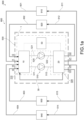
- the fluidic command device 1 comprises four inlet ports I1, I2, I3, I4, each one being fluidically connectable to a respective operating group 910, 920, 930, 940 to allow the working fluid to enter into the fluidic command device 1.
- the fluidic command device 1 receives working fluid from the respective operating groups 910, 920, 930, 940.
- the fluidic command device 1 comprises four outlet ports O1, O2, O3, O4, each one being fluidically connectable to a respective operating group 910, 920, 930, 940 to allow the working fluid to exit from the fluidic command device 1.
- the fluidic command device 1 releases working fluid to the respective operating groups 910, 920, 930, 940.
- the fluidic command device 1 comprises an auxiliary duct 30, which fluidically connects the first pump group 510 and the second pump group 520.
- the auxiliary duct 30 is a bypass duct, which directly connects the first pump group 510 and the second pump group 520.
- the auxiliary duct 30 connects the first pump group 510 directly to the second pump group 520 so that no operating group is fluidically present between the two pump groups.
- the fluidic command device 1 is configurable in a first working configuration, in which the working fluid flows into the first inlet port I1 and flows out from the first outlet port O1, thus preventing the flow through the other inlet ports and the other outlet ports; in said first configuration, the working fluid flows between the first inlet port I1 and the first outlet port O1 into the first pump group 510, the auxiliary duct 30 and the second pump group 520.
- the first working configuration is diagrammatically shown by way of example in figures 2a and 2a' .
- the fluidic command device 1 in the first working configuration, is configured to identify a single fluid circuit in which the temperature of the first operating group 910 is managed. In yet other words, in the first working configuration, the fluidic command device 1 is configured to manage the temperature of the first operating group 910 using the first pump group 510 and the second pump group 520 in series.
- the fluidic command device 1 is configurable in a second working configuration, in which the working fluid flows into the second inlet port I2 and flows out from the second outlet port O2, thus preventing the flow through the other inlet ports and the other outlet ports; in which, between the second inlet port I2 and the second outlet port O2, the working fluid flows both in the first pump group 510 and in the second pump group 520, thus preventing the flow in the auxiliary duct 30.
- the second working configuration is diagrammatically shown by way of example in figures 2b and 2b' .
- the fluidic command device 1 in the second working configuration, is configured to identify a single fluid circuit in which the temperature of the second operating group 920 is managed. In yet other words, in the second working configuration, the fluidic command device 1 is configured to manage the temperature of the second operating group 920 using the first pump group 510 and the second pump group 520 in parallel.
- the fluidic command device 1 is configurable in a third working configuration, in which the working fluid flows into the third inlet port I3 and flows out from the third outlet port O3, in which between the third inlet port I3 and the third outlet port O3, the working fluid flows into the first pump group 510, and in which the working fluid flows into the fourth inlet port I4 and flows out from the fourth outlet port O4, in which between the fourth inlet port I4 and the fourth outlet port O4, the working fluid flows into the second pump group 520.
- the third working configuration is diagrammatically shown by way of example in figures 2c and 2c' .
- the fluidic command device 1 in the third working configuration, is configured to identify two distinct fluidic circuits, in which the temperature of the third operating group 930 and of the fourth operating group 940 is managed. In other words, in the third working configuration, the fluidic command device 1 is configured to manage the temperature of the third operating group 930 using one of the two pump groups, e.g. the first pump group 510, and to manage the temperature of the fourth operating group 940 using the remaining pump group, e.g. the second pump group 520.
- the fluidic command device 1 comprises a first command valve element 10 and a second command valve element 20.
- each working configuration corresponds to the regulation of each command valve element 10, 20 to a predetermined position.
- the first command valve element 10 is fluidically connected on one side to the four inlet ports I1, I2, I3, I4 and to the first end of the auxiliary duct 31 and on the other side to the first inlet duct 511 and to the second inlet duct 521.
- the first command valve element 10 is fluidically connected on one side to the operating groups and on the other side to the first pump group 510 and the second pump group 520.
- the first command valve element 10 is suitable for receiving working fluid from the operating groups to direct it towards the first pump group 510 and/or the second pump group 520.
- the second command valve element 20 is fluidically connected on one side to the first outlet duct 512 and second outlet duct 522 and on the other side to a second end of the auxiliary duct 32 and the four outlet ports O1, O2, O3, O4.
- the second command valve element 20 is fluidically connected on one side to the first pump group 510 and to the second pump group 520 and on the other side to the operating groups.
- the second command valve element 20 is suitable for receiving working fluid from the first pump group 510 and/or the second pump group 520 to direct it towards the operating groups.
- both the first command valve element 10 and the second command valve element 20 comprise therein a plurality of command sections, the positioning of which is such as to direct the flow of the working fluid from one side to the other of the respective command valve element.
- the first command valve element 10 extends along a first axis X1-X1.
- the aforesaid different working configurations correspond to different angular positions of the first command valve element 10 with respect to the first axis X1-X1.
- the second command valve element 20 extends along a second axis X2-X2.
- the aforesaid different working configurations correspond to different angular positions of the second command valve element 20 with respect to the second axis X2-X2.
- first axis X1-X1 and the second axis X2-X2 extend parallel to each other.
- the first command valve element 10 and the second command valve element 20 are angularly positionable independently of each other.
- the first command valve element 10 and the second command valve element 20 are angularly positionable at an angle simultaneously with each other.
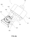
- the fluidic command device 1 comprises command means 50 operatively connected to the first command valve element 10 and the second command valve element 20 suitable to command them to a preferred angular position.
- said command means 50 comprise an active member 51, a first passive member 52' engaged with the active member 51 and the first valve command element 10, and a second passive member 52" engaged with the active member 51 and the second valve command element 20.
- the action of the active member 51 corresponds to a rotation of the first passive member 52' and, therefore, of the first command valve element 10, and to a rotation of the second passive member 52" and, therefore, of the second command valve element 20.
- the active member 51 comprises a gear and the first passive member 52' and the second passive member 52" comprise further gears, respectively, meshing with the active member 51.
- the first passive member 52' and the second passive member 52" extend about the first axis X1-X1 and the second axis X2-X2, respectively.
- the active member 51 is positioned between the first command valve element 10 and the second command valve element 20.
- the active member 51 and the passive members 52', 52" are directly engaged with each other.
- the active member 51 and the passive members 52', 52" are indirectly engaged with each other, e.g. by means of additional motion transmission components, such as other gears or belt elements.
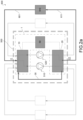
- the fluidic command device 1 comprising a device body 40 suitable to contain the first command valve element 10 and the second command valve element 20.
- the device body 40 comprises a first connecting flange 41 and a second connecting flange 42.
- the first command valve element 10 and the second command valve element 20 are mounted between the first connecting flange 41 and the second connecting flange 42.
- the first connecting flange 41 comprises the four inlet ports I1, I2, I3, I4, and the four outlet ports O1, O2, O3, O4.
- the first connecting flange 41 further comprises the first auxiliary port 310, which is connectable to the first end of the auxiliary duct 31, and the second auxiliary port 320, which is connectable to the second end of the auxiliary duct 32.
- the second connecting flange 42 comprises two pairs of ports for the connection with the first pump group 510 and the second pump group 520, respectively.
- first pair of connection ports 5110, 5210 are suitable for connecting fluidically the first inlet duct 511 and the second inlet duct 521.
- Said first pair of connection ports 5110, 5210 is fluidically connected to the first command valve element 10.
- the second pair of connection ports 5120, 5220 is suitable for putting the first inlet duct 512 and the second inlet duct 522 into fluid communication.
- Said second pair of connection ports 5120, 5220 is fluidically connected to the second command valve element 20.
- the first command valve element 10 and the second command valve element 20 comprise said command sections, the development of which is such as to direct the flow of working fluid between one connecting flange and the other, and, therefore, between the various components fluidically connected to said flanges.
- some command sections are suitable for joining two inlet flows into a single outlet flow, or vice versa.
- some command sections are suitable for connecting a respective inlet with a respective outlet.
- the fluidic command device 1 is highly compact in size so that it is suitable for being accommodated in the engine compartment of a vehicle.
- the two pump groups have the features described in document 102018000010971 to the Applicant, as also shown as an example in the accompanying figures.
- the present invention further relates to the thermal regulation system 600 of a vehicle, which comprises said thermal management assembly 500 having the features described above.
- Said vehicle comprises a first operating group 910, a second operating group 920, a third operating group 930, and a fourth operating group 940
- the thermal regulation system 600 comprises a plurality of system ducts 601, 602, 603, 604, 611, 612, 613, 614 suitable to be fluidically connected the first operating group 910, the second operating group 920, the third operating group 930 and with the fourth operating group 940.
- said system ducts 601, 602, 603, 604, 611, 612, 613, 614 are suitable for being fluidically connected to the described thermal management assembly 500.
- the present invention also relates to a vehicle 900, which comprises a first operating group 910, e.g. an endothermic engine group, a second operating group 920, e.g. a first battery group and a second battery group, a third operating group 930, e.g. comprising the first battery group and a first electric motor group, a fourth operating group 940, e.g. comprising the second battery group and a second electric motor group.
- the vehicle 900 of the present invention further comprises a thermal regulation system 600.
- said vehicle 900 is hybrid-powered, in which the first operating group 910 is an endothermic engine group, the second operating group 920 is a first battery group and a second battery group, the third operating group 930 is the first battery group and a first electric motor group, the fourth operating group 940 is the second battery group and a second electric motor group.
- an embodiment of the vehicle 900 of this type is a vehicle with an endothermic engine group, and which has, for example on an electrically driven axle, an electric power group (with respective battery group) for each wheel group.
- the thermal management assembly the thermal regulation system of a vehicle, which comprises such a management assembly and the vehicle which comprises the thermal regulation system largely fulfill the purpose of the present invention by solving the problems which emerged in typical solutions of the prior art.
- the fluidic command device of the present invention allows the regulation of a plurality of operating groups of the vehicle.
- the fluidic command device of the present invention allows simple management of the temperature of different operating groups of the vehicle, using only two pump groups.
- the fluidic command device is of simple positioning in the vehicle, having compact dimensions and, therefore, compact overall dimensions.
- the fluidic command device is cost-effective to manufacture.
- the fluidic command device of the present invention manages the temperature of the vehicle in a highly effective and flexible manner.
- the fluidic command device of the present invention manages the temperature of the vehicle in a plurality of different operating conditions, i.e. both in motion and stationary.
- the fluidic command device is suitable, in the first working configuration, for managing the temperature of the endothermic engine group.
- the thermal management assembly exclusively manages the temperature of said "endothermic drive part".
- the fluidic command device is suitable, in the first configuration, for managing the temperature of an operating group such as the endothermic engine group by virtue of a double working fluid flow.
- the fluidic command device is suitable, in the second configuration, for managing the temperature of two electric motor groups and respective battery groups.
- the thermal management assembly exclusively manages the temperature of said "electric drive part".
- the fluidic command device is suitable, in the second configuration, to manage the temperature of an operating group with high load losses, such as the battery group, the battery groups, by virtue of a double head.
- the temperature of the battery groups is managed separately from the temperature of the respective electric motor groups and, obviously, of the endothermic engine group; for example, this configuration applies in situations in which the vehicle is stationary, e.g. when recharging the battery group, or when starting the vehicle and starting the battery group.
- the fluid management device is suitable for switching from one configuration to another.
- the fluid management device is configurable in the desired working configuration.
Landscapes
- Engineering & Computer Science (AREA)
- General Engineering & Computer Science (AREA)
- Mechanical Engineering (AREA)
- Chemical & Material Sciences (AREA)
- Combustion & Propulsion (AREA)
- Transportation (AREA)
- Air-Conditioning For Vehicles (AREA)
- Multiple-Way Valves (AREA)
- Cooling, Air Intake And Gas Exhaust, And Fuel Tank Arrangements In Propulsion Units (AREA)
- Arrangement And Mounting Of Devices That Control Transmission Of Motive Force (AREA)
- Quick-Acting Or Multi-Walled Pipe Joints (AREA)
- Exhaust Gas After Treatment (AREA)
Claims (15)
- Fluidische Steuervorrichtung (1) einer Wärmeverwaltungsanordnung (500) eines Wärmeregulierungssystems (600) eines Fahrzeugs (900), wobei das Fahrzeug (900) vier Betriebsgruppen (910, 920, 930, 940) aufweist, wobei die Wärmeverwaltungsanordnung (500) aufweist:i) eine erste Pumpengruppe (510), die geeignet ist, um die Bewegung des Arbeitsfluids in der Wärmeverwaltungsanordnung (500) zu steuern, die einen ersten Einlasskanal (511) und einen ersten Auslasskanal (512) aufweist;ii) eine zweite Pumpengruppe (520), die wiederrum geeignet ist, die Bewegung des Arbeitsfluids in der Wärmeverwaltungsanordnung (500) zu steuern, die einen zweiten Einlasskanal (521) und einen zweiten Auslasskanal (522) aufweist;wobei die fluidische Steuervorrichtung (1) dadurch gekennzeichnet, dass sie ein erstes Paar Anschlüsse (5110, 5210) und ein zweites Paar Anschlüsse (510, 520) aufweist, das mit dem ersten Paar Kanäle (511, 512) und mit dem zweiten Paar Kanäle (521, 522) fluidisch verbindbar ist und aufweist:- vier Einlassanschlüsse (I1, I2, I3, I4), die jeweils mit einer jeweiligen Betriebsgruppe (910, 920, 930, 940) fluidisch verbindbar sind, um es dem Arbeitsfluid zu ermöglichen, in die fluidische Steuervorrichtung (1) einzutreten;- vier Auslassanschlüsse (O1, O2, O3, O4), die jeweils mit einer jeweiligen Betriebsgruppe (910, 920, 930, 940) fluidisch verbindbar sind, um es dem Arbeitsfluid zu ermöglichen, aus der fluidischen Steuervorrichtung (1) auszutreten;- einen Nebenkanal (30), der die erste Pumpengruppe (510) und die zweite Pumpengruppe (520) fluidisch verbindet;wobei die fluidische Steuervorrichtung (1) konfigurierbar ist in:l) einer ersten Arbeitskonfiguration, in der das Arbeitsfluid in den ersten Einlassanschluss (I1) einströmt und aus dem ersten Auslassanschluss (01) ausströmt und somit die Strömung durch den anderen Einlass- und den anderen Auslassanschluss verhindert wird, wobei zwischen dem ersten Einlassanschluss (I1) und dem ersten Auslassanschluss (01) das Arbeitsfluid in die erste Pumpengruppe (510), den Nebenkanal (30) und die zweite Pumpengruppe (520) einströmt;m) einer zweiten Arbeitskonfiguration, in der das Arbeitsfluid in den zweiten Einlassanschluss (I2) einströmt und aus dem zweiten Auslassanschluss (O2) ausströmt und somit die Strömung durch die anderen Einlassanschlüsse und die anderen Auslassanschlüsse verhindert wird, wobei zwischen dem zweiten Einlassanschluss (I2) und dem zweiten Auslassanschluss (O2) das Arbeitsfluid sowohl in die erste Pumpengruppe (510) als auch in die zweite Pumpengruppe (520) einströmt, wodurch die Strömung in den Nebenkanal (30) verhindert wird;n) einer dritten Arbeitskonfiguration, in der das Arbeitsfluid in den dritten Einlassanschluss (I3) einströmt und aus dem dritten Auslassanschluss (O3) ausströmt, wobei zwischen dem dritten Einlassanschluss (I3) und dem dritten Auslassanschluss (O3) das Arbeitsfluid in die erste Pumpengruppe (510) einströmt und wobei das Arbeitsfluid in den vierten Einlassanschluss (I4) einströmt und aus dem vierten Auslassanschluss (O4) ausströmt, wobei zwischen dem vierten Einlassanschluss (I4) und dem vierten Auslassanschluss (O4) das Arbeitsfluid in die zweite Pumpengruppe (520) einströmt.
- Fluidische Steuervorrichtung (1) nach Anspruch 1, wobei die fluidische Steuervorrichtung (1) aufweist:- ein erstes Steuerventilelement (10), das auf einer Seite mit den vier Einlassanschlüssen (I1, I2, I3, I4) und mit einem ersten Ende des Nebenkanals (31) und auf der anderen Seite mit dem ersten Einlasskanal (511) und mit dem zweiten Einlasskanal (521) fluidisch verbunden ist;- ein zweites Steuerventilelement (20), das auf einer Seite mit dem ersten Auslasskanal (512) und mit dem zweiten Auslasskanal (522) und auf der anderen Seite mit einem zweiten Ende des Nebenkanals (32) und mit den vier Auslassanschlüssen (O1, O2, O3, O4) fluidisch verbunden ist.
- Fluidische Steuervorrichtung (1) nach Anspruch 2, wobei sowohl das erste Steuerventilelement (10) als auch das zweite Steuerventilelement (20) eine Vielzahl von Steuerabschnitten darin aufweisen, deren Positionierung derart ist, dass sie die Strömung des Arbeitsfluids von einer Seite zur anderen des jeweiligen Steuerventilelements lenkt.
- Fluidische Steuervorrichtung (1) nach Anspruch 2 oder Anspruch 3, wobei sich das erste Steuerventilelement (10) entlang einer ersten Achse (X1-X1) erstreckt und sich das zweite Steuerventilelement (20) entlang einer zweiten Achse (X2-X2) erstreckt, wobei die unterschiedlichen Arbeitskonfigurationen unterschiedlichen Winkelpositionen des ersten Steuerventilelements (10) in Bezug auf die erste Achse (X1-X1) und des zweiten Steuerventilelements (20) in Bezug auf die zweite Achse (X2-X2)entsprechen.
- Fluidische Steuervorrichtung (1) nach Anspruch 4, wobei die fluidische Steuervorrichtung (1) Steuermittel (50) aufweist, die mit dem ersten Steuerventilelement (10) und mit dem zweiten Steuerventilelement (20) betriebswirksam verbunden sind und dazu geeignet sind, um sie in einer bevorzugten Winkelposition zu steuern.
- Fluidische Steuervorrichtung (1) nach Anspruch 5, wobei die Steuermittel (50) ein aktives Glied (51), ein erstes passives Glied (52'), das mit dem aktiven Glied (51) und dem ersten Steuerventilelement (10) in Eingriff steht, sowie ein zweites passives Glied (52"), das mit dem aktiven Glied (51) und mit dem zweiten Steuerventilelement (20) in Eingriff steht, aufweisen, sodass die Wirkung des aktiven Glieds (51) einer Drehung des ersten passives Glieds (52') und somit des ersten Steuerventilelements (10) sowie einer Drehung des zweiten passiven Glieds (52") und somit des zweiten Steuerventilelements (20) entspricht.
- Fluidische Steuervorrichtung (1) nach Anspruch 6, wobei das aktive Glied (51) ein Zahnrad aufweist und das erste passive Glied (52') und das zweite passive Glied (52") jeweils weitere Zahnräder aufweisen, die mit dem aktiven Glied (51), das sich jeweils um die erste Achse (X1-X1) und die zweite Achse (X2-X2) erstreckt, kämmen.
- Fluidische Steuervorrichtung (1) nach einem der vorstehenden Ansprüche in Kombination mit Anspruch 3, wobei die fluidische Steuervorrichtung (1) einen Vorrichtungskörper (40) aufweist, der geeignet ist, um das erste Steuerventilelement (10) und das zweite Steuerventilelement (20) aufzunehmen, wobei der Vorrichtungskörper (40) einen ersten Verbindungsflansch (41) und einen zweiten Verbindungsflansch (42) aufweist, wobei das erste Steuerventilelement (10) und das zweite Steuerventilelement (20) zwischen dem ersten Verbindungsflansch (41) und dem zweiten Verbindungsflansch (42) montiert sind.
- Fluidische Steuervorrichtung (1) nach Anspruch 8, wobei der erste Verbindungsflansch (41) die vier Einlassanschlüsse (I1, I2, I3, I4) und die vier Auslassanschlüsse (O1, O2, O3, O4) aufweist.
- Fluidische Steuervorrichtung (1) nach Anspruch 9, wobei der erste Verbindungsflansch (41) ferner den ersten Nebenanschluss (310), der mit dem ersten Ende des Nebenkanals (31) verbindbar ist, und den zweiten Nebenanschluss (320), der mit dem zweiten Ende des Nebenkanals (32) verbindbar ist, aufweist.
- Wärmeverwaltungsanordnung (500) eines Wärmeregulierungssystems (600) eines Fahrzeugs (900), wobei das Fahrzeug (900) eine erste Betriebsgruppe (910), eine zweite Betriebsgruppe (920), eine dritte Betriebsgruppe (930) und eine vierte Betriebsgruppe (940) aufweist;
wobei die Wärmeverwaltungsanordnung (500) aufweist:- ein fluidische Steuervorrichtung (1) nach einem der vorstehenden Ansprüche;- eine erste Pumpengruppe (510), die geeignet ist, um die Bewegung des Arbeitsfluids in der Wärmeverwaltungsanordnung (500) zu steuern, die einen ersten Einlasskanal (511) und einen ersten Auslasskanal (512) aufweist, aufweisend:i) eine erste Steuereinheit (513), aufweisend ein erstes Flügelrad, das im ersten Einlasskanal (511) strömendes Arbeitsfluid abfängt und zum ersten Auslasskanal (512) leitet;ii) einen ersten Stabilisierungstank (514), der den ersten Einlasskanal (511) in einen ersten Stromaufwärts-Kanalabschnitt (511') und einen ersten Stromabwärts-Kanalabschnitt (511") unterteilt;- eine zweite Pumpengruppe (520), die wiederum geeignet ist, um die Bewegung des Arbeitsfluids in der Wärmeverwaltungsanordnung (500) zu steuern, die einen zweiten Einlasskanal (521) und einen zweiten Auslasskanal (522) aufweist, aufweisend:l) eine zweite Steuereinheit (523), die ein zweites Flügelrad aufweist, welches das in den zweiten Einlasskanal (521) strömende Arbeitsfluid abfängt, um es in den zweiten Auslasskanal (522) zu leiten;m) einen zweiten Stabilisierungstank (524), der den zweiten Einlasskanal (521) in einen zweiten Stromaufwärts-Kanalabschnitt (521') und einen zweiten Stromabwärts-Kanalabschnitt (521") unterteilt. - Wärmeverwaltungsanordnung (500) nach Anspruch 11, wobei der Nebenkanal (30) den ersten Auslasskanal (512) fluidisch mit dem zweiten Einlasskanal (521) verbindet, vorzugsweise stromaufwärts des möglichen zweiten Stabilisierungstanks (524).
- Wärmeregulierungssystem (600) für ein Fahrzeug (900), wobei das Fahrzeug (900) eine erste Betriebsgruppe (910), eine zweite Betriebsgruppe (920), eine dritte Betriebsgruppe (930) und eine vierte Betriebsgruppe (940) aufweist, wobei das Wärmeregulierungssystem (600) aufweist:- eine Vielzahl von Systemkanälen (601, 602, 603, 604, 611, 612, 613, 614), die mit einer ersten Betriebsgruppe (910), einer zweiten Betriebsgruppe (920), einer dritten Betriebsgruppe (930) und einer vierten Betriebsgruppe (940) fluidisch verbunden sind; und- eine Wärmeverwaltungsanordnung (500), die mit den Systemkanälen (601, 602, 603, 604, 611, 612, 613, 614) nach einem der Ansprüche 11 oder 12 fluidisch verbunden ist.
- Fahrzeug (900), aufweisend eine erste Betriebsgruppe (910), z.B. eine endotherme Motorgruppe, eine zweite Betriebsgruppe (920), z.B. eine erste Batteriegruppe und eine zweite Batteriegruppe, eine dritte Betriebsgruppe (930), z.B. aufweisend die erste Batteriegruppe und eine erste Elektromotorgruppe, eine vierte Betriebsgruppe (940), z.B. aufweisend die zweite Batteriegruppe und eine zweite Elektromotorgruppe, sowie ein Wärmeregulierungssystem (600) nach Anspruch 13.
- Hybrid angetriebenes Fahrzeug (900) nach Anspruch 14, aufweisend die erste Betriebsgruppe (910), die eine endotherme Motorgruppe aufweist, die zweite Betriebsgruppe (920), die eine erste Batteriegruppe und eine zweite Batteriegruppe aufweist, und die dritte Betriebsgruppe (930), welche die erste Batteriegruppe und eine erste Elektromotorgruppe aufweist, wobei die vierte Betriebsgruppe (940) die zweite Batteriegruppe und eine zweite Elektromotorgruppe aufweist.
Applications Claiming Priority (2)
| Application Number | Priority Date | Filing Date | Title |
|---|---|---|---|
| IT102019000018704A IT201900018704A1 (it) | 2019-10-14 | 2019-10-14 | Dispositivo di comando fluidico di un veicolo |
| PCT/IB2020/059506 WO2021074755A1 (en) | 2019-10-14 | 2020-10-09 | Fluidic command device of a vehicle |
Publications (2)
| Publication Number | Publication Date |
|---|---|
| EP4045781A1 EP4045781A1 (de) | 2022-08-24 |
| EP4045781B1 true EP4045781B1 (de) | 2023-08-02 |
Family
ID=69570766
Family Applications (1)
| Application Number | Title | Priority Date | Filing Date |
|---|---|---|---|
| EP20799825.3A Active EP4045781B1 (de) | 2019-10-14 | 2020-10-09 | Fluidische steuervorrichtung für ein fahrzeug |
Country Status (6)
| Country | Link |
|---|---|
| US (1) | US20220397052A1 (de) |
| EP (1) | EP4045781B1 (de) |
| CN (1) | CN114667387B (de) |
| IT (1) | IT201900018704A1 (de) |
| MX (1) | MX2022003006A (de) |
| WO (1) | WO2021074755A1 (de) |
Families Citing this family (1)
| Publication number | Priority date | Publication date | Assignee | Title |
|---|---|---|---|---|
| IT201900018701A1 (it) * | 2019-10-14 | 2021-04-14 | Ind Saleri Italo Spa | Assieme di gestione termica di un veicolo |
Family Cites Families (26)
| Publication number | Priority date | Publication date | Assignee | Title |
|---|---|---|---|---|
| US4553566A (en) * | 1984-04-06 | 1985-11-19 | The United States Of America As Represented By The United States Department Of Energy | Rotary multiposition valve |
| JPH05131848A (ja) * | 1991-11-15 | 1993-05-28 | Toyota Motor Corp | ハイブリツド車の駆動システム制御装置 |
| FR2832187B1 (fr) * | 2001-11-13 | 2005-08-05 | Valeo Thermique Moteur Sa | Systeme de gestion de l'energie thermique developpee par un moteur thermique de vehicule automobile |
| US6616059B2 (en) * | 2002-01-04 | 2003-09-09 | Visteon Global Technologies, Inc. | Hybrid vehicle powertrain thermal management system and method for cabin heating and engine warm up |
| JP4795332B2 (ja) * | 2004-02-26 | 2011-10-19 | ベンテック,エルエルシー | 乗り物補助加熱システム |
| FR2936566B1 (fr) * | 2008-09-30 | 2010-10-15 | Renault Sas | Circuit de refroidissement pour la regulation thermique du moteur independamment des autres consommateurs |
| FR2969050B1 (fr) * | 2010-12-21 | 2014-10-17 | Renault Sa | Procede et systeme de regulation de la temperature d'une batterie d'alimentation d'un vehicule a traction electrique et vehicule equipe d'un tel systeme |
| DE102012019005B4 (de) * | 2011-09-30 | 2023-08-17 | Audi Ag | Thermisches Konditionieren eines einen Elektroantrieb aufweisenden Kraftfahrzeugs |
| JP5880863B2 (ja) * | 2012-02-02 | 2016-03-09 | 株式会社デンソー | 車両用熱管理システム |
| JP5910517B2 (ja) * | 2012-02-02 | 2016-04-27 | 株式会社デンソー | 熱交換器 |
| JP6060797B2 (ja) * | 2012-05-24 | 2017-01-18 | 株式会社デンソー | 車両用熱管理システム |
| ITBS20120111A1 (it) * | 2012-07-19 | 2014-01-20 | Ind Saleri Italo Spa | Gruppo valvola per impianto raffreddamento veicoli |
| DE102012220452B4 (de) * | 2012-11-09 | 2023-10-05 | Bayerische Motoren Werke Aktiengesellschaft | Wärmemanagementsystem für ein Kraftfahrzeug |
| JP6064753B2 (ja) * | 2013-04-05 | 2017-01-25 | 株式会社デンソー | 車両用熱管理システム |
| JP6065779B2 (ja) * | 2013-07-31 | 2017-01-25 | 株式会社デンソー | 車両用熱管理システム |
| JP6197671B2 (ja) * | 2014-01-29 | 2017-09-20 | 株式会社デンソー | 空調装置 |
| CN203939592U (zh) * | 2014-06-26 | 2014-11-12 | 河南工程学院 | 基于温差发电的lng热管理系统 |
| EP3156659B1 (de) * | 2015-10-12 | 2020-09-16 | Grundfos Holding A/S | Pumpenaggregat und hydraulisches system |
| US10718256B2 (en) * | 2016-05-03 | 2020-07-21 | GM Global Technology Operations LLC | Powertrain thermal management system and method |
| JP6493300B2 (ja) * | 2016-05-19 | 2019-04-03 | 株式会社デンソー | 流路切替弁 |
| FR3051873B1 (fr) * | 2016-05-24 | 2018-06-15 | Peugeot Citroen Automobiles Sa | Groupe motopropulseur d’un vehicule |
| DE102016113394B3 (de) * | 2016-07-20 | 2017-10-19 | Ino8 Pty Ltd | Wärmemanagementsystem und -verfahren einer variablen Zylinderkühlung eines Verbrennungsmotors |
| CA3048231A1 (en) * | 2016-12-21 | 2018-06-28 | A & A International, Llc | Hydraulic clutches, gearboxes, transmissions, and energy recovery systems |
| GB2558914B (en) * | 2017-01-19 | 2021-03-31 | Arrival Ltd | Thermal management unit and system |
| US10557401B2 (en) * | 2017-06-26 | 2020-02-11 | GM Global Technology Operations LLC | Thermal management systems, coolant valves and control logic for vehicle powertrains |
| FR3070721B1 (fr) * | 2017-09-07 | 2019-08-30 | Psa Automobiles Sa | Ensemble d’un circuit de refroidissement pour un moteur thermique avec boucle d’aerotherme |
-
2019
- 2019-10-14 IT IT102019000018704A patent/IT201900018704A1/it unknown
-
2020
- 2020-10-09 EP EP20799825.3A patent/EP4045781B1/de active Active
- 2020-10-09 US US17/642,881 patent/US20220397052A1/en not_active Abandoned
- 2020-10-09 CN CN202080064269.XA patent/CN114667387B/zh active Active
- 2020-10-09 MX MX2022003006A patent/MX2022003006A/es unknown
- 2020-10-09 WO PCT/IB2020/059506 patent/WO2021074755A1/en not_active Ceased
Also Published As
| Publication number | Publication date |
|---|---|
| EP4045781A1 (de) | 2022-08-24 |
| WO2021074755A1 (en) | 2021-04-22 |
| CN114667387A (zh) | 2022-06-24 |
| CN114667387B (zh) | 2024-07-05 |
| IT201900018704A1 (it) | 2021-04-14 |
| US20220397052A1 (en) | 2022-12-15 |
| MX2022003006A (es) | 2022-06-16 |
Similar Documents
| Publication | Publication Date | Title |
|---|---|---|
| EP3936709B1 (de) | Bauteilgehäuseeinheit und fahrzeugwärmemanagementsystem mit einer bauteilgehäuseeinheit | |
| KR102673317B1 (ko) | 자동차용 변속기 윤활 및 클러치 냉각을 위한 유압 장치 | |
| US8668467B2 (en) | Integrated fluid handling apparatus | |
| EP4045781B1 (de) | Fluidische steuervorrichtung für ein fahrzeug | |
| EP4045780B1 (de) | Anordnung zur thermischen verwaltung eines fahrzeugs | |
| WO2025223161A1 (zh) | 壳体集成流道的双电机动力总成及车辆 | |
| EP4045779B1 (de) | Fluidiksteuerungsvorrichtung für ein fahrzeug | |
| EP3549799A1 (de) | Wärmeverwaltungssystem für fahrzeug | |
| KR20220037957A (ko) | 급수 모듈 및 이를 포함한 전장 냉각 시스템 | |
| CN113978707A (zh) | 一种刹车控制系统、控制方法及飞行器 | |
| EP4045778B1 (de) | Anordnung zur thermischen verwaltung eines fahrzeugs | |
| CN119497785A (zh) | 车辆的供应模块壳体、车辆的供应模块和车辆 | |
| US20260012063A1 (en) | Cooling system for rotary electric machine | |
| CN120419083A (zh) | 用于在电牵引驱动装置中根据需要分配冷却油流/润滑油流的装置和方法 | |
| US20240120807A1 (en) | Cooling system for an electric traction machine for a motor vehicle | |
| EP4292852A2 (de) | Schaltbares pumpenflussschema | |
| CN118407916A (zh) | 齿轮泵 | |
| KR20260005324A (ko) | 유압 시스템 및 자동차 | |
| CN119891639A (zh) | 油冷动力总成及电动车辆 |
Legal Events
| Date | Code | Title | Description |
|---|---|---|---|
| STAA | Information on the status of an ep patent application or granted ep patent |
Free format text: STATUS: UNKNOWN |
|
| STAA | Information on the status of an ep patent application or granted ep patent |
Free format text: STATUS: THE INTERNATIONAL PUBLICATION HAS BEEN MADE |
|
| PUAI | Public reference made under article 153(3) epc to a published international application that has entered the european phase |
Free format text: ORIGINAL CODE: 0009012 |
|
| STAA | Information on the status of an ep patent application or granted ep patent |
Free format text: STATUS: REQUEST FOR EXAMINATION WAS MADE |
|
| 17P | Request for examination filed |
Effective date: 20220223 |
|
| AK | Designated contracting states |
Kind code of ref document: A1 Designated state(s): AL AT BE BG CH CY CZ DE DK EE ES FI FR GB GR HR HU IE IS IT LI LT LU LV MC MK MT NL NO PL PT RO RS SE SI SK SM TR |
|
| DAV | Request for validation of the european patent (deleted) | ||
| DAX | Request for extension of the european patent (deleted) | ||
| GRAP | Despatch of communication of intention to grant a patent |
Free format text: ORIGINAL CODE: EPIDOSNIGR1 |
|
| STAA | Information on the status of an ep patent application or granted ep patent |
Free format text: STATUS: GRANT OF PATENT IS INTENDED |
|
| INTG | Intention to grant announced |
Effective date: 20230414 |
|
| GRAS | Grant fee paid |
Free format text: ORIGINAL CODE: EPIDOSNIGR3 |
|
| P01 | Opt-out of the competence of the unified patent court (upc) registered |
Effective date: 20230523 |
|
| GRAA | (expected) grant |
Free format text: ORIGINAL CODE: 0009210 |
|
| STAA | Information on the status of an ep patent application or granted ep patent |
Free format text: STATUS: THE PATENT HAS BEEN GRANTED |
|
| AK | Designated contracting states |
Kind code of ref document: B1 Designated state(s): AL AT BE BG CH CY CZ DE DK EE ES FI FR GB GR HR HU IE IS IT LI LT LU LV MC MK MT NL NO PL PT RO RS SE SI SK SM TR |
|
| REG | Reference to a national code |
Ref country code: GB Ref legal event code: FG4D |
|
| REG | Reference to a national code |
Ref country code: CH Ref legal event code: EP |
|
| REG | Reference to a national code |
Ref country code: DE Ref legal event code: R096 Ref document number: 602020015135 Country of ref document: DE |
|
| REG | Reference to a national code |
Ref country code: IE Ref legal event code: FG4D |
|
| REG | Reference to a national code |
Ref country code: LT Ref legal event code: MG9D |
|
| REG | Reference to a national code |
Ref country code: NL Ref legal event code: MP Effective date: 20230802 |
|
| REG | Reference to a national code |
Ref country code: AT Ref legal event code: MK05 Ref document number: 1595000 Country of ref document: AT Kind code of ref document: T Effective date: 20230802 |
|
| PG25 | Lapsed in a contracting state [announced via postgrant information from national office to epo] |
Ref country code: GR Free format text: LAPSE BECAUSE OF FAILURE TO SUBMIT A TRANSLATION OF THE DESCRIPTION OR TO PAY THE FEE WITHIN THE PRESCRIBED TIME-LIMIT Effective date: 20231103 |
|
| PG25 | Lapsed in a contracting state [announced via postgrant information from national office to epo] |
Ref country code: IS Free format text: LAPSE BECAUSE OF FAILURE TO SUBMIT A TRANSLATION OF THE DESCRIPTION OR TO PAY THE FEE WITHIN THE PRESCRIBED TIME-LIMIT Effective date: 20231202 |
|
| PG25 | Lapsed in a contracting state [announced via postgrant information from national office to epo] |
Ref country code: SE Free format text: LAPSE BECAUSE OF FAILURE TO SUBMIT A TRANSLATION OF THE DESCRIPTION OR TO PAY THE FEE WITHIN THE PRESCRIBED TIME-LIMIT Effective date: 20230802 Ref country code: RS Free format text: LAPSE BECAUSE OF FAILURE TO SUBMIT A TRANSLATION OF THE DESCRIPTION OR TO PAY THE FEE WITHIN THE PRESCRIBED TIME-LIMIT Effective date: 20230802 Ref country code: PT Free format text: LAPSE BECAUSE OF FAILURE TO SUBMIT A TRANSLATION OF THE DESCRIPTION OR TO PAY THE FEE WITHIN THE PRESCRIBED TIME-LIMIT Effective date: 20231204 Ref country code: NO Free format text: LAPSE BECAUSE OF FAILURE TO SUBMIT A TRANSLATION OF THE DESCRIPTION OR TO PAY THE FEE WITHIN THE PRESCRIBED TIME-LIMIT Effective date: 20231102 Ref country code: NL Free format text: LAPSE BECAUSE OF FAILURE TO SUBMIT A TRANSLATION OF THE DESCRIPTION OR TO PAY THE FEE WITHIN THE PRESCRIBED TIME-LIMIT Effective date: 20230802 Ref country code: LV Free format text: LAPSE BECAUSE OF FAILURE TO SUBMIT A TRANSLATION OF THE DESCRIPTION OR TO PAY THE FEE WITHIN THE PRESCRIBED TIME-LIMIT Effective date: 20230802 Ref country code: LT Free format text: LAPSE BECAUSE OF FAILURE TO SUBMIT A TRANSLATION OF THE DESCRIPTION OR TO PAY THE FEE WITHIN THE PRESCRIBED TIME-LIMIT Effective date: 20230802 Ref country code: IS Free format text: LAPSE BECAUSE OF FAILURE TO SUBMIT A TRANSLATION OF THE DESCRIPTION OR TO PAY THE FEE WITHIN THE PRESCRIBED TIME-LIMIT Effective date: 20231202 Ref country code: HR Free format text: LAPSE BECAUSE OF FAILURE TO SUBMIT A TRANSLATION OF THE DESCRIPTION OR TO PAY THE FEE WITHIN THE PRESCRIBED TIME-LIMIT Effective date: 20230802 Ref country code: GR Free format text: LAPSE BECAUSE OF FAILURE TO SUBMIT A TRANSLATION OF THE DESCRIPTION OR TO PAY THE FEE WITHIN THE PRESCRIBED TIME-LIMIT Effective date: 20231103 Ref country code: FI Free format text: LAPSE BECAUSE OF FAILURE TO SUBMIT A TRANSLATION OF THE DESCRIPTION OR TO PAY THE FEE WITHIN THE PRESCRIBED TIME-LIMIT Effective date: 20230802 Ref country code: AT Free format text: LAPSE BECAUSE OF FAILURE TO SUBMIT A TRANSLATION OF THE DESCRIPTION OR TO PAY THE FEE WITHIN THE PRESCRIBED TIME-LIMIT Effective date: 20230802 |
|
| PG25 | Lapsed in a contracting state [announced via postgrant information from national office to epo] |
Ref country code: PL Free format text: LAPSE BECAUSE OF FAILURE TO SUBMIT A TRANSLATION OF THE DESCRIPTION OR TO PAY THE FEE WITHIN THE PRESCRIBED TIME-LIMIT Effective date: 20230802 |
|
| PG25 | Lapsed in a contracting state [announced via postgrant information from national office to epo] |
Ref country code: ES Free format text: LAPSE BECAUSE OF FAILURE TO SUBMIT A TRANSLATION OF THE DESCRIPTION OR TO PAY THE FEE WITHIN THE PRESCRIBED TIME-LIMIT Effective date: 20230802 |
|
| PG25 | Lapsed in a contracting state [announced via postgrant information from national office to epo] |
Ref country code: SM Free format text: LAPSE BECAUSE OF FAILURE TO SUBMIT A TRANSLATION OF THE DESCRIPTION OR TO PAY THE FEE WITHIN THE PRESCRIBED TIME-LIMIT Effective date: 20230802 Ref country code: RO Free format text: LAPSE BECAUSE OF FAILURE TO SUBMIT A TRANSLATION OF THE DESCRIPTION OR TO PAY THE FEE WITHIN THE PRESCRIBED TIME-LIMIT Effective date: 20230802 Ref country code: ES Free format text: LAPSE BECAUSE OF FAILURE TO SUBMIT A TRANSLATION OF THE DESCRIPTION OR TO PAY THE FEE WITHIN THE PRESCRIBED TIME-LIMIT Effective date: 20230802 Ref country code: EE Free format text: LAPSE BECAUSE OF FAILURE TO SUBMIT A TRANSLATION OF THE DESCRIPTION OR TO PAY THE FEE WITHIN THE PRESCRIBED TIME-LIMIT Effective date: 20230802 Ref country code: DK Free format text: LAPSE BECAUSE OF FAILURE TO SUBMIT A TRANSLATION OF THE DESCRIPTION OR TO PAY THE FEE WITHIN THE PRESCRIBED TIME-LIMIT Effective date: 20230802 Ref country code: CZ Free format text: LAPSE BECAUSE OF FAILURE TO SUBMIT A TRANSLATION OF THE DESCRIPTION OR TO PAY THE FEE WITHIN THE PRESCRIBED TIME-LIMIT Effective date: 20230802 Ref country code: SK Free format text: LAPSE BECAUSE OF FAILURE TO SUBMIT A TRANSLATION OF THE DESCRIPTION OR TO PAY THE FEE WITHIN THE PRESCRIBED TIME-LIMIT Effective date: 20230802 |
|
| REG | Reference to a national code |
Ref country code: DE Ref legal event code: R097 Ref document number: 602020015135 Country of ref document: DE |
|
| PG25 | Lapsed in a contracting state [announced via postgrant information from national office to epo] |
Ref country code: MC Free format text: LAPSE BECAUSE OF FAILURE TO SUBMIT A TRANSLATION OF THE DESCRIPTION OR TO PAY THE FEE WITHIN THE PRESCRIBED TIME-LIMIT Effective date: 20230802 |
|
| REG | Reference to a national code |
Ref country code: CH Ref legal event code: PL |
|
| PLBE | No opposition filed within time limit |
Free format text: ORIGINAL CODE: 0009261 |
|
| STAA | Information on the status of an ep patent application or granted ep patent |
Free format text: STATUS: NO OPPOSITION FILED WITHIN TIME LIMIT |
|
| REG | Reference to a national code |
Ref country code: BE Ref legal event code: MM Effective date: 20231031 |
|
| PG25 | Lapsed in a contracting state [announced via postgrant information from national office to epo] |
Ref country code: LU Free format text: LAPSE BECAUSE OF NON-PAYMENT OF DUE FEES Effective date: 20231009 |
|
| PG25 | Lapsed in a contracting state [announced via postgrant information from national office to epo] |
Ref country code: LU Free format text: LAPSE BECAUSE OF NON-PAYMENT OF DUE FEES Effective date: 20231009 |
|
| 26N | No opposition filed |
Effective date: 20240503 |
|
| PG25 | Lapsed in a contracting state [announced via postgrant information from national office to epo] |
Ref country code: CH Free format text: LAPSE BECAUSE OF NON-PAYMENT OF DUE FEES Effective date: 20231031 |
|
| PG25 | Lapsed in a contracting state [announced via postgrant information from national office to epo] |
Ref country code: FR Free format text: LAPSE BECAUSE OF NON-PAYMENT OF DUE FEES Effective date: 20231031 Ref country code: CH Free format text: LAPSE BECAUSE OF NON-PAYMENT OF DUE FEES Effective date: 20231031 Ref country code: SI Free format text: LAPSE BECAUSE OF FAILURE TO SUBMIT A TRANSLATION OF THE DESCRIPTION OR TO PAY THE FEE WITHIN THE PRESCRIBED TIME-LIMIT Effective date: 20230802 |
|
| PG25 | Lapsed in a contracting state [announced via postgrant information from national office to epo] |
Ref country code: BE Free format text: LAPSE BECAUSE OF NON-PAYMENT OF DUE FEES Effective date: 20231031 |
|
| PG25 | Lapsed in a contracting state [announced via postgrant information from national office to epo] |
Ref country code: IE Free format text: LAPSE BECAUSE OF NON-PAYMENT OF DUE FEES Effective date: 20231009 |
|
| PG25 | Lapsed in a contracting state [announced via postgrant information from national office to epo] |
Ref country code: IE Free format text: LAPSE BECAUSE OF NON-PAYMENT OF DUE FEES Effective date: 20231009 |
|
| PG25 | Lapsed in a contracting state [announced via postgrant information from national office to epo] |
Ref country code: BG Free format text: LAPSE BECAUSE OF FAILURE TO SUBMIT A TRANSLATION OF THE DESCRIPTION OR TO PAY THE FEE WITHIN THE PRESCRIBED TIME-LIMIT Effective date: 20230802 |
|
| PG25 | Lapsed in a contracting state [announced via postgrant information from national office to epo] |
Ref country code: BG Free format text: LAPSE BECAUSE OF FAILURE TO SUBMIT A TRANSLATION OF THE DESCRIPTION OR TO PAY THE FEE WITHIN THE PRESCRIBED TIME-LIMIT Effective date: 20230802 |
|
| GBPC | Gb: european patent ceased through non-payment of renewal fee |
Effective date: 20241009 |
|
| PG25 | Lapsed in a contracting state [announced via postgrant information from national office to epo] |
Ref country code: GB Free format text: LAPSE BECAUSE OF NON-PAYMENT OF DUE FEES Effective date: 20241009 |
|
| PG25 | Lapsed in a contracting state [announced via postgrant information from national office to epo] |
Ref country code: CY Free format text: LAPSE BECAUSE OF FAILURE TO SUBMIT A TRANSLATION OF THE DESCRIPTION OR TO PAY THE FEE WITHIN THE PRESCRIBED TIME-LIMIT; INVALID AB INITIO Effective date: 20201009 |
|
| PG25 | Lapsed in a contracting state [announced via postgrant information from national office to epo] |
Ref country code: HU Free format text: LAPSE BECAUSE OF FAILURE TO SUBMIT A TRANSLATION OF THE DESCRIPTION OR TO PAY THE FEE WITHIN THE PRESCRIBED TIME-LIMIT; INVALID AB INITIO Effective date: 20201009 |
|
| PGFP | Annual fee paid to national office [announced via postgrant information from national office to epo] |
Ref country code: IT Payment date: 20250926 Year of fee payment: 6 |
|
| PG25 | Lapsed in a contracting state [announced via postgrant information from national office to epo] |
Ref country code: TR Free format text: LAPSE BECAUSE OF FAILURE TO SUBMIT A TRANSLATION OF THE DESCRIPTION OR TO PAY THE FEE WITHIN THE PRESCRIBED TIME-LIMIT Effective date: 20230802 |
|
| PGFP | Annual fee paid to national office [announced via postgrant information from national office to epo] |
Ref country code: DE Payment date: 20251027 Year of fee payment: 6 |