EP4045780B1 - Anordnung zur thermischen verwaltung eines fahrzeugs - Google Patents
Anordnung zur thermischen verwaltung eines fahrzeugs Download PDFInfo
- Publication number
- EP4045780B1 EP4045780B1 EP20799824.6A EP20799824A EP4045780B1 EP 4045780 B1 EP4045780 B1 EP 4045780B1 EP 20799824 A EP20799824 A EP 20799824A EP 4045780 B1 EP4045780 B1 EP 4045780B1
- Authority
- EP
- European Patent Office
- Prior art keywords
- group
- command
- duct
- thermal management
- valve element
- Prior art date
- Legal status (The legal status is an assumption and is not a legal conclusion. Google has not performed a legal analysis and makes no representation as to the accuracy of the status listed.)
- Active
Links
Images


Classifications
-
- F—MECHANICAL ENGINEERING; LIGHTING; HEATING; WEAPONS; BLASTING
- F01—MACHINES OR ENGINES IN GENERAL; ENGINE PLANTS IN GENERAL; STEAM ENGINES
- F01P—COOLING OF MACHINES OR ENGINES IN GENERAL; COOLING OF INTERNAL-COMBUSTION ENGINES
- F01P7/00—Controlling of coolant flow
- F01P7/14—Controlling of coolant flow the coolant being liquid
- F01P7/16—Controlling of coolant flow the coolant being liquid by thermostatic control
- F01P7/165—Controlling of coolant flow the coolant being liquid by thermostatic control characterised by systems with two or more loops
-
- B—PERFORMING OPERATIONS; TRANSPORTING
- B60—VEHICLES IN GENERAL
- B60K—ARRANGEMENT OR MOUNTING OF PROPULSION UNITS OR OF TRANSMISSIONS IN VEHICLES; ARRANGEMENT OR MOUNTING OF PLURAL DIVERSE PRIME-MOVERS IN VEHICLES; AUXILIARY DRIVES FOR VEHICLES; INSTRUMENTATION OR DASHBOARDS FOR VEHICLES; ARRANGEMENTS IN CONNECTION WITH COOLING, AIR INTAKE, GAS EXHAUST OR FUEL SUPPLY OF PROPULSION UNITS IN VEHICLES
- B60K11/00—Arrangement in connection with cooling of propulsion units
- B60K11/02—Arrangement in connection with cooling of propulsion units with liquid cooling
-
- B—PERFORMING OPERATIONS; TRANSPORTING
- B60—VEHICLES IN GENERAL
- B60K—ARRANGEMENT OR MOUNTING OF PROPULSION UNITS OR OF TRANSMISSIONS IN VEHICLES; ARRANGEMENT OR MOUNTING OF PLURAL DIVERSE PRIME-MOVERS IN VEHICLES; AUXILIARY DRIVES FOR VEHICLES; INSTRUMENTATION OR DASHBOARDS FOR VEHICLES; ARRANGEMENTS IN CONNECTION WITH COOLING, AIR INTAKE, GAS EXHAUST OR FUEL SUPPLY OF PROPULSION UNITS IN VEHICLES
- B60K6/00—Arrangement or mounting of plural diverse prime-movers for mutual or common propulsion, e.g. hybrid propulsion systems comprising electric motors and internal combustion engines
- B60K6/20—Arrangement or mounting of plural diverse prime-movers for mutual or common propulsion, e.g. hybrid propulsion systems comprising electric motors and internal combustion engines the prime-movers consisting of electric motors and internal combustion engines, e.g. HEVs
- B60K6/22—Arrangement or mounting of plural diverse prime-movers for mutual or common propulsion, e.g. hybrid propulsion systems comprising electric motors and internal combustion engines the prime-movers consisting of electric motors and internal combustion engines, e.g. HEVs characterised by apparatus, components or means specially adapted for HEVs
- B60K6/24—Arrangement or mounting of plural diverse prime-movers for mutual or common propulsion, e.g. hybrid propulsion systems comprising electric motors and internal combustion engines the prime-movers consisting of electric motors and internal combustion engines, e.g. HEVs characterised by apparatus, components or means specially adapted for HEVs characterised by the combustion engines
-
- B—PERFORMING OPERATIONS; TRANSPORTING
- B60—VEHICLES IN GENERAL
- B60K—ARRANGEMENT OR MOUNTING OF PROPULSION UNITS OR OF TRANSMISSIONS IN VEHICLES; ARRANGEMENT OR MOUNTING OF PLURAL DIVERSE PRIME-MOVERS IN VEHICLES; AUXILIARY DRIVES FOR VEHICLES; INSTRUMENTATION OR DASHBOARDS FOR VEHICLES; ARRANGEMENTS IN CONNECTION WITH COOLING, AIR INTAKE, GAS EXHAUST OR FUEL SUPPLY OF PROPULSION UNITS IN VEHICLES
- B60K6/00—Arrangement or mounting of plural diverse prime-movers for mutual or common propulsion, e.g. hybrid propulsion systems comprising electric motors and internal combustion engines
- B60K6/20—Arrangement or mounting of plural diverse prime-movers for mutual or common propulsion, e.g. hybrid propulsion systems comprising electric motors and internal combustion engines the prime-movers consisting of electric motors and internal combustion engines, e.g. HEVs
- B60K6/22—Arrangement or mounting of plural diverse prime-movers for mutual or common propulsion, e.g. hybrid propulsion systems comprising electric motors and internal combustion engines the prime-movers consisting of electric motors and internal combustion engines, e.g. HEVs characterised by apparatus, components or means specially adapted for HEVs
- B60K6/26—Arrangement or mounting of plural diverse prime-movers for mutual or common propulsion, e.g. hybrid propulsion systems comprising electric motors and internal combustion engines the prime-movers consisting of electric motors and internal combustion engines, e.g. HEVs characterised by apparatus, components or means specially adapted for HEVs characterised by the motors or the generators
-
- B—PERFORMING OPERATIONS; TRANSPORTING
- B60—VEHICLES IN GENERAL
- B60K—ARRANGEMENT OR MOUNTING OF PROPULSION UNITS OR OF TRANSMISSIONS IN VEHICLES; ARRANGEMENT OR MOUNTING OF PLURAL DIVERSE PRIME-MOVERS IN VEHICLES; AUXILIARY DRIVES FOR VEHICLES; INSTRUMENTATION OR DASHBOARDS FOR VEHICLES; ARRANGEMENTS IN CONNECTION WITH COOLING, AIR INTAKE, GAS EXHAUST OR FUEL SUPPLY OF PROPULSION UNITS IN VEHICLES
- B60K6/00—Arrangement or mounting of plural diverse prime-movers for mutual or common propulsion, e.g. hybrid propulsion systems comprising electric motors and internal combustion engines
- B60K6/20—Arrangement or mounting of plural diverse prime-movers for mutual or common propulsion, e.g. hybrid propulsion systems comprising electric motors and internal combustion engines the prime-movers consisting of electric motors and internal combustion engines, e.g. HEVs
- B60K6/22—Arrangement or mounting of plural diverse prime-movers for mutual or common propulsion, e.g. hybrid propulsion systems comprising electric motors and internal combustion engines the prime-movers consisting of electric motors and internal combustion engines, e.g. HEVs characterised by apparatus, components or means specially adapted for HEVs
- B60K6/28—Arrangement or mounting of plural diverse prime-movers for mutual or common propulsion, e.g. hybrid propulsion systems comprising electric motors and internal combustion engines the prime-movers consisting of electric motors and internal combustion engines, e.g. HEVs characterised by apparatus, components or means specially adapted for HEVs characterised by the electric energy storing means, e.g. batteries or capacitors
-
- B—PERFORMING OPERATIONS; TRANSPORTING
- B60—VEHICLES IN GENERAL
- B60L—PROPULSION OF ELECTRICALLY-PROPELLED VEHICLES; SUPPLYING ELECTRIC POWER FOR AUXILIARY EQUIPMENT OF ELECTRICALLY-PROPELLED VEHICLES; ELECTRODYNAMIC BRAKE SYSTEMS FOR VEHICLES IN GENERAL; MAGNETIC SUSPENSION OR LEVITATION FOR VEHICLES; MONITORING OPERATING VARIABLES OF ELECTRICALLY-PROPELLED VEHICLES; ELECTRIC SAFETY DEVICES FOR ELECTRICALLY-PROPELLED VEHICLES
- B60L58/00—Methods or circuit arrangements for monitoring or controlling batteries or fuel cells, specially adapted for electric vehicles
- B60L58/10—Methods or circuit arrangements for monitoring or controlling batteries or fuel cells, specially adapted for electric vehicles for monitoring or controlling batteries
- B60L58/24—Methods or circuit arrangements for monitoring or controlling batteries or fuel cells, specially adapted for electric vehicles for monitoring or controlling batteries for controlling the temperature of batteries
-
- F—MECHANICAL ENGINEERING; LIGHTING; HEATING; WEAPONS; BLASTING
- F01—MACHINES OR ENGINES IN GENERAL; ENGINE PLANTS IN GENERAL; STEAM ENGINES
- F01P—COOLING OF MACHINES OR ENGINES IN GENERAL; COOLING OF INTERNAL-COMBUSTION ENGINES
- F01P3/00—Liquid cooling
- F01P3/20—Cooling circuits not specific to a single part of engine or machine
-
- F—MECHANICAL ENGINEERING; LIGHTING; HEATING; WEAPONS; BLASTING
- F01—MACHINES OR ENGINES IN GENERAL; ENGINE PLANTS IN GENERAL; STEAM ENGINES
- F01P—COOLING OF MACHINES OR ENGINES IN GENERAL; COOLING OF INTERNAL-COMBUSTION ENGINES
- F01P5/00—Pumping cooling-air or liquid coolants
- F01P5/10—Pumping liquid coolant; Arrangements of coolant pumps
- F01P2005/105—Using two or more pumps
-
- F—MECHANICAL ENGINEERING; LIGHTING; HEATING; WEAPONS; BLASTING
- F01—MACHINES OR ENGINES IN GENERAL; ENGINE PLANTS IN GENERAL; STEAM ENGINES
- F01P—COOLING OF MACHINES OR ENGINES IN GENERAL; COOLING OF INTERNAL-COMBUSTION ENGINES
- F01P7/00—Controlling of coolant flow
- F01P7/14—Controlling of coolant flow the coolant being liquid
- F01P2007/146—Controlling of coolant flow the coolant being liquid using valves
-
- F—MECHANICAL ENGINEERING; LIGHTING; HEATING; WEAPONS; BLASTING
- F01—MACHINES OR ENGINES IN GENERAL; ENGINE PLANTS IN GENERAL; STEAM ENGINES
- F01P—COOLING OF MACHINES OR ENGINES IN GENERAL; COOLING OF INTERNAL-COMBUSTION ENGINES
- F01P2050/00—Applications
- F01P2050/24—Hybrid vehicles
-
- F—MECHANICAL ENGINEERING; LIGHTING; HEATING; WEAPONS; BLASTING
- F01—MACHINES OR ENGINES IN GENERAL; ENGINE PLANTS IN GENERAL; STEAM ENGINES
- F01P—COOLING OF MACHINES OR ENGINES IN GENERAL; COOLING OF INTERNAL-COMBUSTION ENGINES
- F01P2060/00—Cooling circuits using auxiliaries
-
- F—MECHANICAL ENGINEERING; LIGHTING; HEATING; WEAPONS; BLASTING
- F04—POSITIVE - DISPLACEMENT MACHINES FOR LIQUIDS; PUMPS FOR LIQUIDS OR ELASTIC FLUIDS
- F04D—NON-POSITIVE-DISPLACEMENT PUMPS
- F04D13/00—Pumping installations or systems
- F04D13/12—Combinations of two or more pumps
-
- F—MECHANICAL ENGINEERING; LIGHTING; HEATING; WEAPONS; BLASTING
- F04—POSITIVE - DISPLACEMENT MACHINES FOR LIQUIDS; PUMPS FOR LIQUIDS OR ELASTIC FLUIDS
- F04D—NON-POSITIVE-DISPLACEMENT PUMPS
- F04D15/00—Control, e.g. regulation, of pumps, pumping installations or systems
- F04D15/0005—Control, e.g. regulation, of pumps, pumping installations or systems by using valves
Definitions
- the present invention relates to a thermal management assembly of a thermal regulation system of a vehicle. Additionally, the present invention relates to the thermal regulation system of a vehicle, which comprises said thermal management assembly. Furthermore, the present invention also relates to a vehicle that comprises said system and comprises said thermal management assembly.
- the present invention relates to the automotive field, and in detail to the thermal regulation system of a vehicle.
- vehicle relates to any means of transport without any limitation as to type or size, i.e. a motor vehicle or a semi-articulated vehicle.
- operating group means a specific component or group of components for carrying out a given operation required for the motion of the vehicle. Therefore, for example, operating group means the endothermic engine group, or the battery group, or the gearbox group, or the transmission group, or the electric motor group, or the battery group.
- an "operating group” comprises one or more components or groups of components also comprised in other distinct “operating groups”.
- each operating group has different needs.
- each of said operating groups has a mutually different operating behavior, both while the vehicle is in motion and when it is stationary (e.g. the electric motor operates in situations with the endothermic engine in standby). Therefore, it is apparent that each operating group has different needs for thermal management, cooling and/or heating, as a function of the different operating situations of the vehicle and as a function of its physical features.
- Vehicle solutions which comprise a specific thermal regulation system for each operating group, in which a specific amount of working fluid circulates.
- each specific thermal regulation system is designed independently, requiring specific components (e.g. specific pump groups).
- Such an object is achieved by a thermal management assembly as claimed in claim 1. Similarly, such an object is achieved by a thermal regulation system of a vehicle, which comprises such a thermal management assembly, as claimed in claim 14. Furthermore, such an object is achieved by a vehicle, which comprises the thermal regulation system according to claim 15.
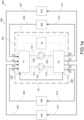
- reference numeral 500 indicates as a whole a thermal management assembly of a thermal regulation system 600 of a vehicle 900 (diagrammatically shown in the figures), according to the present invention.
- the present invention also relates to the thermal regulation system 600, which comprises the thermal management assembly 500.
- the present invention also relates to the vehicle 900 which comprises the thermal regulation system 600.
- said vehicle 900 is hybrid-powered, i.e. is powered in combination by an endothermic engine and at least one electric motor group electrically supplied by a respective battery group.
- the vehicle 900 comprises an endothermic engine group with power supply and two electric motor groups powered by two battery groups, respectively.
- the vehicle 900 comprises a first operating group 910, a second operating group 920, a third operating group 930, and a fourth operating group 940.
- Each operating group corresponds to a "load”.
- each operating group corresponds to a respective component or group of components comprised in the vehicle and preferably belonging to the power supply of the vehicle.
- the first operating group 910 is an endothermic engine group.
- the second operating group 920 comprising a first battery group and a second battery group.
- the third operating group 930 comprises the first battery group and a first electric motor group.
- the fourth operating group 940 comprises the second battery group and a second electric motor group.
- the first operating group 910, the second operating group 920, the third operating group 930, and the fourth operating group 940 are fluidically connected to the thermal regulation system 600.
- the first operating group 910, the second operating group 920, the third operating group 930, and the fourth operating group 940 are fluidically connected by means of a plurality of system ducts 601, 602, 603, 604, 611, 612, 613, 614 comprised in the thermal regulation system 600.
- the thermal regulation system 600 further comprises specific heat exchanger groups (not shown).
- the thermal regulation system 600 comprises at least one system inlet duct and at least one system outlet duct in fluidic connection with each operating group.
- the thermal management assembly 500 comprises a first pump group 510 suitable to command the motion of the working fluid comprising a first inlet duct 511 and a first outlet duct 512.
- the thermal management assembly 500 comprises a second pump group 520 suitable, in turn, to command the motion of the working fluid comprising a second inlet duct 521 and a second outlet duct 522.
- the first pump group 510 comprises a first command unit 513 comprising a first impeller, which intercepts the working fluid flowing in the first inlet duct 511 to send it into the first outlet duct 512.
- said first impeller is of the radial type, aspirating working fluid axially through the first inlet duct 511 to push it out tangentially towards the first outlet duct 512.
- the first pump group 510 further comprises a first stabilization tank 514, which divides the first inlet duct 511 into a first duct upstream section 511' and a first duct downstream section 511".
- said first stabilization tank 514 unifies the pressure of the flowing liquid before it reaches the first impeller comprised in the first command unit 513.
- the working fluid reaches the first command unit 513 after having flowed in the first stabilization tank 514.
- the second pump group 520 comprises a second command unit 523 comprising a second impeller, which intercepts the working fluid flowing in the second inlet duct 521 to send it into the second outlet duct 522.
- said second impeller is of the radial type, aspirating working fluid axially through the second inlet duct 521 to push it out tangentially towards the second outlet duct 522.
- the second pump group 520 further comprises a second stabilization tank 524, which divides the second inlet duct 521 into a second duct upstream section 521' and a second duct downstream section 521".
- said second stabilization tank 524 unifies the pressure of the flowing liquid before it reaches the second impeller comprised in the second command unit 523.
- the working fluid reaches the second command unit 523 after having flowed in the second stabilization tank 524.
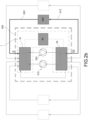
- the thermal management assembly 500 further comprises a fluidic command device 1 suitable to manage the amounts of working fluid flowing in the thermal management assembly 500.
- the fluidic command device 1 is fluidically connected to the first pair of ducts 511, 512 and to the second pair of ducts 521, 522. Thereby, the fluidic command device 1 is suitable for managing through which of these ducts the working fluid flows.
- fluidic command device 1 is fluidically connectable by means of system ducts to the respective operating groups.
- the fluidic command device 1 comprises four inlet ports I1, I2, I3, I4, each one being fluidically connectable to a respective operating group 910, 920, 930, 940 to allow the working fluid to enter into the fluidic command device 1.
- the fluidic command device 1 receives working fluid from the respective operating groups 910, 920, 930, 940.
- the fluidic command device 1 comprises four outlet ports O1, O2, O3, O4, each one being fluidically connectable to a respective operating group 910, 920, 930, 940 to allow the working fluid to exit from the fluidic command device 1.
- the fluidic command device 1 releases working fluid to the respective operating groups 910, 920, 930, 940.
- the fluidic command device 1 comprises an auxiliary duct 30, which fluidically connects the first pump group 510 and the second pump group 520.
- the auxiliary duct 30 is a bypass duct, which directly connects the first pump group 510 and the second pump group 520.
- the auxiliary duct 30 connects the first pump group 510 directly to the second pump group 520 so that no operating group is fluidically present between the two pump groups.
- the fluidic command device 1 is configurable in a first working configuration, in which the working fluid flows into the first inlet port I1 and flows out from the first outlet port O1, thus preventing the flow through the other inlet ports and the other outlet ports; in said first configuration, the working fluid flows between the first inlet port I1 and the first outlet port O1 into the first pump group 510, the auxiliary duct 30 and the second pump group 520.
- the first working configuration is diagrammatically shown by way of example in figures 2a and 2a' .
- the fluidic command device 1 in the first working configuration, is configured to identify a single fluidic circuit in which the temperature of the first operating group 910 is managed. In yet other words, in the first working configuration, the fluidic command device 1 is configured to manage the temperature of the first operating group 910 using the first pump group 510 and the second pump group 520 in series.
- the fluidic command device 1 is configurable in a second working configuration, in which the working fluid flows into the second inlet port I2 and flows out from the second outlet port 02, thus preventing the flow through the other inlet ports and the other outlet ports; in which, between the second inlet port I2 and the second outlet port 02, the working fluid flows both in the first pump group 510 and in the second pump group 520, thus preventing the flow in the auxiliary duct 30.
- the second working configuration is diagrammatically shown by way of example in figures 2b and 2b' .
- the fluidic command device 1 in the second working configuration, is configured to identify a single fluidic circuit in which the temperature of the second operating group 920 is managed. In yet other words, in the second working configuration, the fluidic command device 1 is configured to manage the temperature of the second operating group 920 using the first pump group 510 and the second pump group 520 in parallel.
- the fluidic command device 1 is configurable in a third working configuration, in which the working fluid flows into the third inlet port I3 and flows out from the third outlet port 03, in which between the third inlet port I3 and the third outlet port 03, the working fluid flows into the first pump group 510, and in which the working fluid flows into the fourth inlet port I4 and flows out from the fourth outlet port 04, in which between the fourth inlet port I4 and the fourth outlet port 04, the working fluid flows into the second pump group 520.
- the third working configuration is diagrammatically shown by way of example in figures 2c and 2c' .
- the fluidic command device 1 in the third working configuration, is configured to identify two distinct fluidic circuits in which the temperature of the third operating group 930 and of the fourth operating group 940 is managed. In other words, in the third working configuration, the fluidic command device 1 is configured to manage the temperature of the third operating group 930 using one of the two pump groups, e.g. the first pump group 510, and to manage the temperature of the fourth operating group 940 using the remaining pump group, e.g. the second pump group 520.
- the fluidic command device 1 comprises a first command valve element 10 and a second command valve element 20.
- each working configuration corresponds to the regulation of each command valve element 10, 20 to a predetermined position.
- the first command valve element 10 is fluidically connected on one side to the four inlet ports I1, I2, I3, I4 and the first end of the auxiliary duct 30 and on the other side to the first inlet duct 511 and the second inlet duct 521.
- the first command valve element 10 is fluidically connected on one side to the operating groups and on the other side to the first pump group 510 and the second pump group 520.
- the first command valve element 10 is suitable for receiving working fluid from the operating groups on the other side to direct it towards the first pump group 510 and/or the second pump group 520.
- the second command valve element 20 is fluidically connected on one side to the first outlet duct 512 and second outlet duct 522 and on the other side to a second end of the auxiliary duct 32 and the four outlet ports O1, O2, O3, O4.
- the second command valve element 20 is fluidically connected on one side to the first pump group 510 and to the second pump group 520 and on the other side to the operating groups.
- the second command valve element 20 is suitable for receiving working fluid from the first pump group 510 and/or the second pump group 520 to direct it towards the operating groups.
- both the first command valve element 10 and the second command valve element 20 comprise therein a plurality of command sections, the positioning of which is such as to direct the flow of the working fluid from one side to the other of the respective command valve element.
- the first command valve element 10 extends along a first axis X1-X1.
- the aforesaid different working configurations correspond to different angular positions of the first command valve element 10 with respect to the first axis X1-X1.
- the second command valve element 20 extends along a second axis X2-X2.
- the aforesaid different working configurations correspond to different angular positions of the second command valve element 20 with respect to the second axis X2-X2.
- first axis X1-X1 and the second axis X2-X2 extend parallel to each other.
- the first command valve element 10 and the second command valve element 20 are angularly positionable independently of each other.
- the first command valve element 10 and the second command valve element 20 are angularly positionable simultaneously with each other.
- the fluidic command device 1 comprises command means 50 operatively connected to the first command valve element 10 and the second command valve element 20 suitable to command them to a preferred angular position.
- said command means 50 comprise an active member 51, a first passive member 52' engaged with the active member 51 and the first valve command element 10, and a second passive member 52" engaged with the active member 51 and the second valve command element 20.
- the action of the active member 51 corresponds to a rotation of the first passive member 52' and therefore of the first command valve element 10, and to a rotation of the second passive member 52" and therefore of the second command valve element 20.
- the active member 51 comprises a gear and the first passive member 52', and the second passive member 52" comprise further gears, respectively, meshing with the active member 51.
- the first passive member 52' and the second passive member 52" extend about the first axis X1-X1 and the second axis X2-X2, respectively.
- the active member 51 is positioned between the first command valve element 10 and the second command valve element 20.
- the active member 51 and the passive members 52', 52" are directly engaged with each other.
- the active member 51 and the passive members 52', 52" are indirectly engaged with each other, e.g. by means of additional motion transmission components, such as other gears or belt elements.
- the fluidic command device 1 comprising a device body 40 suitable to contain the first command valve element 10 and the second command valve element 20.
- the device body 40 comprises a first connecting flange 41 and a second connecting flange 42.
- the first command valve element 10 and the second command valve element 20 are mounted between the first connecting flange 41 and the second connecting flange 42.
- the first connecting flange 41 comprises the four inlet ports I1, I2, I3, I4, and the four outlet ports O1, O2, O3, O4.
- the first connecting flange 41 further comprises the first auxiliary port 310 which is connectable to the first end of the auxiliary duct 30, and the second auxiliary port 320 which is connectable to the second end of the auxiliary duct 32.
- the second connecting flange 42 comprises two pairs of ports for the connection with the first pump group 510 and the second pump group 520, respectively.
- first pair of connection ports 5110, 5210 are suitable for connecting fluidically the first inlet duct 511 and the second inlet duct 521.
- Said first pair of connection ports 5110, 5210 is fluidically connected to the first command valve element 10.
- the second pair of connection ports 5120, 5220 is suitable for putting the first inlet duct 512 and the second inlet duct 522 into fluidic communication.
- Said second pair of connection ports 5120, 5220 is fluidically connected to the second command valve element 20.
- the first command valve element 10 and the second command valve element 20 comprise said command sections, the development of which is such as to direct the flow of working fluid between one connecting flange and the other, and therefore between the various components fluidically connected to said flanges.
- some command sections are suitable for joining two inlet flows into a single outlet flow, or vice versa.
- some command sections are suitable to connect a respective inlet with a respective outlet.
- the fluidic command device 1 is highly compact in size so that it is suitable for being accommodated in the engine compartment of a vehicle.
- the two pump groups have the features described in document 102018000010971 to the Applicant, as also shown as an example in the accompanying figures.
- the present invention further relates to the thermal regulation system 600 of a vehicle, which comprises said thermal management assembly 500 having the features described above.
- Said vehicle comprises a first operating group 910, a second operating group 920, a third operating group 930, and a fourth operating group 940
- the thermal regulation system 600 comprises a plurality of system ducts 601, 602, 603, 604, 611, 612, 613, 614 suitable to be fluidically connected the first operating group 910, the second operating group 920, the third operating group 930 and the fourth operating group 940.
- said system ducts 601, 602, 603, 604, 611, 612, 613, 614 are suitable for being fluidically connected to the described thermal management assembly 500.
- the present invention also relates to a vehicle 900 which comprises a first operating group 910, e.g. an endothermic engine group, a second operating group 920, e.g. a first battery group and a second battery group, a third operating group 930, e.g. comprising the first battery group and a first electric motor group, a fourth operating group 940, e.g. comprising the second battery group and a second electric motor group.
- the vehicle 900 of the present invention further comprises a thermal regulation system 600.
- said vehicle 900 is hybrid-powered, in which the first operating group 910 is an endothermic engine group, the second operating group 920 is a first battery group and a second battery group, the third operating group 930 is the first battery group and a first electric motor group, the fourth operating group 940 is the second battery group and a second electric motor group.
- an embodiment of the vehicle 900 of this type is a vehicle with an endothermic engine group, and which has, for example on an electrically driven axle, an electric power group (with respective battery group) for each wheel group.
- the thermal management system the thermal regulation system of a vehicle which comprises such a management assembly and the vehicle which comprises the thermal regulation system largely fulfill the purpose of the present invention by solving the problems emerged in typical solutions of the prior art.
- the thermal management assembly of the present invention allows the regulation of a plurality of operating groups of the vehicle.
- the thermal management assembly of the present invention allows simple management of the temperature of different operating groups of the vehicle, using only two pump groups.
- the thermal management assembly is of simple positioning in the vehicle, having a compact size and, therefore, compact overall dimensions.
- the thermal management assembly is cost-effective to manufacture.
- the thermal management assembly of the present invention manages the temperature of the vehicle in a highly effective and flexible manner.
- the thermal management assembly of the present invention manages the temperature of the vehicle in a plurality of different operating conditions, i.e. both in motion and stationary.
- the thermal management assembly is suitable, in the first working configuration, for managing the temperature of the endothermic engine group.
- the thermal management assembly exclusively manages the temperature of said "endothermic drive part".
- the thermal management assembly is suitable, in the first configuration, for managing the temperature of an operating group such as the endothermic engine group by virtue of a double working fluid flow.
- the thermal management assembly is suitable, in the second configuration, for managing the temperature of two electric motor groups and respective battery groups.
- the thermal management assembly exclusively manages the temperature of said "electric drive part".
- the thermal management assembly is suitable in the second configuration to manage the temperature of an operating group with high load losses, such as the battery group, the battery groups, by virtue of a double head.
- the temperature of the battery groups is managed separately from the temperature of the respective electric motor groups and, obviously, of the endothermic engine group; for example, this configuration applies in situations in which the vehicle is stationary, e.g. when recharging the battery group, or when starting the vehicle and starting the battery group.
- the fluidic management device is suitable for switching from one configuration to another.
- the fluidic management device is configurable in the desired working configuration.
Landscapes
- Engineering & Computer Science (AREA)
- Mechanical Engineering (AREA)
- Chemical & Material Sciences (AREA)
- Combustion & Propulsion (AREA)
- Transportation (AREA)
- General Engineering & Computer Science (AREA)
- Life Sciences & Earth Sciences (AREA)
- Sustainable Development (AREA)
- Sustainable Energy (AREA)
- Power Engineering (AREA)
- Cooling, Air Intake And Gas Exhaust, And Fuel Tank Arrangements In Propulsion Units (AREA)
- Air-Conditioning For Vehicles (AREA)
- Quick-Acting Or Multi-Walled Pipe Joints (AREA)
- Automobile Manufacture Line, Endless Track Vehicle, Trailer (AREA)
Claims (16)
- Thermomanagement-Anordnung (500) eines Thermoregelungssystems (600) eines Fahrzeugs (900), wobei das Fahrzeug (900) vier Betriebsgruppen (910, 920, 930, 940) umfasst, wobei die Thermomanagement-Anordnung (500) Folgendes umfasst:i) eine erste Pumpenbaugruppe (510), die geeignet ist, die Bewegung des Arbeitsfluids in der Thermomanagement-Anordnung zu befehlen, umfassend einen ersten Einlasskanal (511) und einen ersten Auslasskanal (512) umfasst,ii) eine zweite Pumpengruppe (520), die ihrerseits dafür geeignet ist, die Bewegung des Arbeitsfluids in der Thermomanagement-Anordnung (500) zu befehlen, umfassend einen zweiten Einlasskanal (521) und einen zweiten Auslasskanal (522);iii) eine Fluidbefehlsvorrichtung (1), die fluidisch mit dem ersten Paar von Kanälen (511, 512) und dem zweiten Paar von Kanälen (521, 522) verbunden ist,wobei die Thermomanagement-Anordnung (500) dadurch gekennzeichnet ist, dass die Fluidbefehlsvorrichtung (1) ferner Folgendes umfasst:- vier Einlassöffnungen (I1, I2, I3, I4), von denen jede fluidisch mit einer jeweiligen Betriebsgruppe (910, 920, 930, 940) verbindbar ist, um dem Arbeitsfluid zu ermöglichen, in die Fluidbefehlsvorrichtung (1) einzutreten;- vier Auslassöffnungen (O1, O2, O3, O4), von denen jede fluidisch mit einer jeweiligen Betriebsgruppe (910, 920, 930, 940) verbindbar ist, um dem Arbeitsfluid zu ermöglichen, aus der Fluidbefehlsvorrichtung (1) auszutreten;- einen Nebenkanal (30), der die erste Pumpengruppe (510) und die zweite Pumpengruppe (520) fluidisch verbindet;wobei die Fluidbefehlsvorrichtung (1) konfigurierbar ist in:l) einer ersten Arbeitskonfiguration, in der das Arbeitsfluid in die erste Einlassöffnung (I1) einströmt und aus der ersten Auslassöffnung (O1) ausströmt, wodurch das Strömen durch die anderen Einlassöffnungen und die anderen Auslassöffnungen verhindert wird, wobei das Arbeitsfluid, zwischen der ersten Einlassöffnung (I1) und der ersten Auslassöffnung (01), in die erste Pumpengruppe (510), den Nebenkanal (30) und die zweite Pumpengruppe (520) einströmt,m) einer zweiten Arbeitskonfiguration, in der das Arbeitsfluid in die zweite Einlassöffnung (I2) einströmt und aus der zweiten Auslassöffnung (O2) ausströmt, wodurch das Strömen durch die anderen Einlassöffnungen und die anderen Auslassöffnungen verhindert wird, wobei das Arbeitsfluid, zwischen der zweiten Einlassöffnung (I2) und der zweiten Auslassöffnung (O2), sowohl in die erste Pumpengruppe (510) als auch die zweite Pumpengruppe (520) einströmt, wodurch das Einströmen in den Nebenkanal (30) verhindert wird,n) einer dritten Arbeitskonfiguration, in der das Arbeitsfluid in die dritte Einlassöffnung (I3) einströmt und aus der dritten Auslassöffnung (O3) ausströmt, wobei das Arbeitsfluid, zwischen der dritten Einlassöffnung (I3) und der dritten Auslassöffnung (O3), in die erste Pumpengruppe (510) einströmt, und wobei das Arbeitsfluid in die vierte Einlassöffnung (I4) einströmt und aus der vierten Auslassöffnung (O4) ausströmt, wobei das Arbeitsfluid, zwischen der vierten Einlassöffnung (I4) und der vierten Auslassöffnung (O4), in die zweite Pumpengruppe (520) einströmt.
- Thermomanagement-Anordnung (500) nach Anspruch 1, wobei die erste Pumpengruppe (510) Folgendes umfasst:i) eine erste Befehlseinheit (513), die ein erstes Laufrad umfasst, das das Arbeitsfluid, das in dem ersten Einlasskanal (511) strömt, abfängt, um es in den ersten Auslasskanal (512) zu befördern;ii) einen ersten Ausgleichsbehälter (514), der den ersten Einlasskanal (511) in einen stromaufwärts gelegenen Abschnitt (511') des ersten Kanals und einen stromabwärts gelegenen Abschnitt (51 1") des ersten Kanals aufteilt.
- Thermomanagement-Anordnung (500) nach einem beliebigen der vorhergehenden Ansprüche, wobei die zweite Pumpengruppe (520) Folgendes umfasst:i) eine zweite Befehlseinheit (523), die ein zweites Laufrad umfasst, das das Arbeitsfluid, das in dem zweiten Einlasskanal (521) strömt, abfängt, um es in den zweiten Auslasskanal (522) zu befördern;ii) einen zweiten Ausgleichsbehälter (524), der den zweiten Einlasskanal (521) in einen stromaufwärts gelegenen Abschnitt (521') des zweiten Kanals und einen stromabwärts gelegenen Abschnitt (521") des zweiten Kanals aufteilt.
- Thermomanagement-Anordnung (500) nach einem beliebigen der vorhergehenden Ansprüche, wobei der Nebenkanal (30) den ersten Auslasskanal (512), vorzugsweise stromaufwärts von dem möglichen zweiten Ausgleichsbehälter (524), fluidisch mit dem zweiten Einlasskanal (521) verbindet.
- Thermomanagement-Anordnung (500) nach einem beliebigen der vorhergehenden Ansprüche, wobei die Fluidbefehlsvorrichtung (1) Folgendes umfasst:- ein erstes Befehlsventilelement (10), das auf einer Seite mit den vier Einlassöffnungen (I1, I2, I3, I4) und mit einem ersten Ende des Nebenkanals (30), und auf der anderen Seite mit dem ersten Einlasskanal (511) und dem zweiten Einlasskanal (521) fluidisch verbunden ist,- ein zweites Befehlsventilelement (20), das auf einer Seite mit dem ersten Auslasskanal (512) und dem zweiten Auslasskanal (522), und auf der anderen Seite mit einem zweiten Ende des Nebenkanals (32) und den vier Auslassöffnungen (O1, O2, O3, O4) fluidisch verbunden ist.
- Thermomanagement-Anordnung (500) nach Anspruch 5, wobei sowohl das erste Befehlsventilelement (10) als auch das zweite Befehlsventilelement (20) eine Vielzahl von Befehlsabschnitten darin umfassen, deren Positionierung derart ist, dass sie den Strom des Arbeitsfluids von einer Seite zu der anderen des jeweiligen Befehlsventilelements leiten.
- Thermomanagement-Anordnung (500) nach Anspruch 5 oder Anspruch 6, wobei sich das erste Befehlsventilelement (10) entlang einer ersten Achse (X1-X1) erstreckt und sich das zweite Befehlsventilelement (20) entlang einer zweiten Achse (X2-X2) erstreckt, wobei die unterschiedlichen Arbeitskonfigurationen unterschiedlichen Winkelpositionen des ersten Befehlsventilelements (10) in Bezug auf die erste Achse (X1-X1) und des zweiten Befehlsventilelements (20) in Bezug auf die zweite Achse (X2-X2) entsprechen.
- Thermomanagement-Anordnung (500) nach Anspruch 7, wobei die Fluidbefehlsvorrichtung (1) Befehlsmittel (50) umfasst, die betriebsfähig mit dem ersten Befehlsventilelement (10) und dem zweiten Befehlsventilelement (20) verbunden sind, geeignet, diese in eine bevorzugte Winkelposition zu bringen.
- Thermomanagement-Anordnung (500) nach Anspruch 8, wobei die Befehlsmittel (50) ein aktives Element (51), ein erstes passives Element (52'), das mit dem aktiven Element (51) und dem ersten Ventilbefehlselement (10) im Eingriff ist, und ein zweites passives Element (52"), das mit dem aktiven Element (51) und dem zweiten Ventilbefehlselement (20) im Eingriff ist, umfassen, sodass die Wirkung des aktiven Elements (51) einer Drehung des ersten passiven Elements (52') und damit des ersten Befehlsventilelements (10), und einer Drehung des zweiten passiven Elements (52") und damit des zweiten Befehlsventilelements (20) entspricht.
- Thermomanagement-Anordnung (500) nach Anspruch 9, wobei das aktive Element (51) ein Zahnrad umfasst, und das erste passive Element (52') und das zweite passive Element (52") jeweils weitere Zahnräder umfassen, die in das aktive Element (51) eingreifen sich jeweils um die erste Achse (X1-X1) und die zweite Achse (X2-X2) erstreckend.
- Thermomanagement-Anordnung (500) nach einem beliebigen der vorhergehenden Ansprüche in Verbindung mit Anspruch 5, wobei die Fluidbefehlsvorrichtung (1) einen Vorrichtungskörper (40) umfasst, der geeignet ist, das erste Befehlsventilelement (10) und das zweite Befehlsventilelement (20) aufzunehmen, wobei der Vorrichtungskörper (40) einen ersten Verbindungsflansch (41) und einen zweiten Verbindungsflansch (42) umfasst, wobei das erste Befehlsventilelement (10) und das zweite Befehlsventilelement (20) zwischen dem ersten Verbindungsflansch (41) und dem zweiten Verbindungsflansch (42) montiert sind.
- Thermomanagement-Anordnung (500) nach Anspruch 11, wobei der erste Verbindungsflansch (41) die vier Einlassöffnungen (I1, I2, I3, I4) und die vier Auslassöffnungen (O1, O2, O3, O4) umfasst.
- Thermomanagement-Anordnung (500) nach Anspruch 12, wobei der erste Verbindungsflansch (41) ferner die erste Nebenöffnung (310), die mit dem ersten Ende des Nebenkanals (30) verbindbar ist, und die zweite Nebenöffnung (320), die mit dem zweiten Ende des Nebenkanals (32) verbindbar ist, umfasst.
- Thermoregelungssystem (600) eines Fahrzeugs, wobei das Fahrzeug eine erste Betriebsgruppe (910), eine zweite Betriebsgruppe (920), eine dritte Betriebsgruppe (930) und eine vierte Betriebsgruppe (940) umfasst, wobei das Thermoregelungssystem (600) Folgendes umfasst:- eine Vielzahl von Systemkanälen (601, 602, 603, 604, 611, 612, 613, 614), die fluidisch mit einer ersten Betriebsgruppe (910), einer zweiten Betriebsgruppe (920), einer dritten Betriebsgruppe (930) und einer vierten Betriebsgruppe (940) verbunden sind, und- eine Thermomanagement-Anordnung (500) nach einem beliebigen der vorhergehenden Ansprüche, die fluidisch mit den Systemkanälen (601, 602, 603, 604, 611, 612, 613, 614) verbunden ist.
- Fahrzeug (900), das eine erste Betriebsgruppe (910), z. B. eine endotherme Motorgruppe, eine zweite Betriebsgruppe (920), z. B. eine erste Batteriegruppe und eine zweite Batteriegruppe, eine dritte Betriebsgruppe (930), die z. B. die erste Batteriegruppe und eine erste Elektromotorengruppe umfasst, eine vierte Betriebsgruppe (940), die z. B. die zweite Batteriegruppe und eine zweite Elektromotorengruppe umfasst, und ein Thermoregelungssystem (600) nach Anspruch 14 umfasst.
- Fahrzeug (900) mit Hybridantrieb nach Anspruch 15, umfassend die erste Betriebsgruppe (910), die eine endotherme Motorgruppe umfasst, die zweite Betriebsgruppe (920), die eine erste Batteriegruppe und eine zweite Batteriegruppe umfasst, die dritte Betriebsgruppe (930), die die erste Batteriegruppe und eine erste Elektromotorengruppe umfasst, die vierte Betriebsgruppe (940), die die zweite Batteriegruppe und eine zweite Elektromotorengruppe umfasst.
Applications Claiming Priority (2)
| Application Number | Priority Date | Filing Date | Title |
|---|---|---|---|
| IT102019000018701A IT201900018701A1 (it) | 2019-10-14 | 2019-10-14 | Assieme di gestione termica di un veicolo |
| PCT/IB2020/059505 WO2021074754A1 (en) | 2019-10-14 | 2020-10-09 | Thermal management assembly of a vehicle |
Publications (2)
| Publication Number | Publication Date |
|---|---|
| EP4045780A1 EP4045780A1 (de) | 2022-08-24 |
| EP4045780B1 true EP4045780B1 (de) | 2023-07-19 |
Family
ID=69570765
Family Applications (1)
| Application Number | Title | Priority Date | Filing Date |
|---|---|---|---|
| EP20799824.6A Active EP4045780B1 (de) | 2019-10-14 | 2020-10-09 | Anordnung zur thermischen verwaltung eines fahrzeugs |
Country Status (6)
| Country | Link |
|---|---|
| US (1) | US11919383B2 (de) |
| EP (1) | EP4045780B1 (de) |
| CN (1) | CN114729592B (de) |
| IT (1) | IT201900018701A1 (de) |
| MX (1) | MX2022003007A (de) |
| WO (1) | WO2021074754A1 (de) |
Families Citing this family (1)
| Publication number | Priority date | Publication date | Assignee | Title |
|---|---|---|---|---|
| DE102021214729A1 (de) * | 2021-12-20 | 2023-06-22 | Mahle International Gmbh | Kühlsystem |
Family Cites Families (24)
| Publication number | Priority date | Publication date | Assignee | Title |
|---|---|---|---|---|
| JPS56148610A (en) * | 1980-04-18 | 1981-11-18 | Toyota Motor Corp | Cooling device for engine |
| JPS56165713A (en) * | 1980-05-21 | 1981-12-19 | Toyota Motor Corp | Cooler for engine |
| US6616059B2 (en) * | 2002-01-04 | 2003-09-09 | Visteon Global Technologies, Inc. | Hybrid vehicle powertrain thermal management system and method for cabin heating and engine warm up |
| KR100915207B1 (ko) * | 2007-10-16 | 2009-09-02 | 볼보 컨스트럭션 이키프먼트 홀딩 스웨덴 에이비 | 중장비용 유압회로 |
| US20110073285A1 (en) * | 2009-09-30 | 2011-03-31 | Gm Global Technology Operations, Inc. | Multi-Zone Heat Exchanger for Use in a Vehicle Cooling System |
| JP5880863B2 (ja) * | 2012-02-02 | 2016-03-09 | 株式会社デンソー | 車両用熱管理システム |
| JP5910517B2 (ja) * | 2012-02-02 | 2016-04-27 | 株式会社デンソー | 熱交換器 |
| JP6060797B2 (ja) * | 2012-05-24 | 2017-01-18 | 株式会社デンソー | 車両用熱管理システム |
| JP5842755B2 (ja) * | 2012-07-16 | 2016-01-13 | 株式会社デンソー | 車両用熱管理システム |
| JP5983187B2 (ja) * | 2012-08-28 | 2016-08-31 | 株式会社デンソー | 車両用熱管理システム |
| JP5962556B2 (ja) * | 2013-03-19 | 2016-08-03 | 株式会社デンソー | 車両用熱管理システム |
| JP6064753B2 (ja) * | 2013-04-05 | 2017-01-25 | 株式会社デンソー | 車両用熱管理システム |
| US9500299B2 (en) * | 2013-07-25 | 2016-11-22 | Schaeffler Technologies AG & Co. KG | Thermal management valve module with isolated flow chambers |
| JP6065779B2 (ja) * | 2013-07-31 | 2017-01-25 | 株式会社デンソー | 車両用熱管理システム |
| JP6197671B2 (ja) * | 2014-01-29 | 2017-09-20 | 株式会社デンソー | 空調装置 |
| KR101786670B1 (ko) * | 2015-12-10 | 2017-10-18 | 현대자동차 주식회사 | 차량용 냉각 시스템 |
| US10718256B2 (en) * | 2016-05-03 | 2020-07-21 | GM Global Technology Operations LLC | Powertrain thermal management system and method |
| JP6493300B2 (ja) * | 2016-05-19 | 2019-04-03 | 株式会社デンソー | 流路切替弁 |
| US10458313B2 (en) * | 2016-09-27 | 2019-10-29 | Hanon Systems | Multifunctional rotary valve module |
| EP3558736B1 (de) * | 2016-12-21 | 2024-04-17 | A&A International, LLC | Hydraulische kupplungen, getriebekasten, getriebe und energierückgewinnungssysteme |
| US10557401B2 (en) * | 2017-06-26 | 2020-02-11 | GM Global Technology Operations LLC | Thermal management systems, coolant valves and control logic for vehicle powertrains |
| FR3070432B1 (fr) * | 2017-08-30 | 2019-08-16 | Psa Automobiles Sa | Ensemble d’un circuit de refroidissement pour un moteur thermique et une boite de vitesses |
| JP2019173698A (ja) * | 2018-03-29 | 2019-10-10 | トヨタ自動車株式会社 | 車両駆動装置の冷却装置 |
| IT201900018704A1 (it) * | 2019-10-14 | 2021-04-14 | Ind Saleri Italo Spa | Dispositivo di comando fluidico di un veicolo |
-
2019
- 2019-10-14 IT IT102019000018701A patent/IT201900018701A1/it unknown
-
2020
- 2020-10-09 CN CN202080064234.6A patent/CN114729592B/zh active Active
- 2020-10-09 US US17/642,864 patent/US11919383B2/en active Active
- 2020-10-09 MX MX2022003007A patent/MX2022003007A/es unknown
- 2020-10-09 EP EP20799824.6A patent/EP4045780B1/de active Active
- 2020-10-09 WO PCT/IB2020/059505 patent/WO2021074754A1/en not_active Ceased
Also Published As
| Publication number | Publication date |
|---|---|
| CN114729592A (zh) | 2022-07-08 |
| WO2021074754A1 (en) | 2021-04-22 |
| MX2022003007A (es) | 2022-06-16 |
| EP4045780A1 (de) | 2022-08-24 |
| CN114729592B (zh) | 2024-11-01 |
| US20220379717A1 (en) | 2022-12-01 |
| US11919383B2 (en) | 2024-03-05 |
| IT201900018701A1 (it) | 2021-04-14 |
Similar Documents
| Publication | Publication Date | Title |
|---|---|---|
| KR102673317B1 (ko) | 자동차용 변속기 윤활 및 클러치 냉각을 위한 유압 장치 | |
| EP3936709B1 (de) | Bauteilgehäuseeinheit und fahrzeugwärmemanagementsystem mit einer bauteilgehäuseeinheit | |
| US8668467B2 (en) | Integrated fluid handling apparatus | |
| EP4045780B1 (de) | Anordnung zur thermischen verwaltung eines fahrzeugs | |
| EP4045781B1 (de) | Fluidische steuervorrichtung für ein fahrzeug | |
| EP4045779B1 (de) | Fluidiksteuerungsvorrichtung für ein fahrzeug | |
| EP3549799A1 (de) | Wärmeverwaltungssystem für fahrzeug | |
| CN113978707A (zh) | 一种刹车控制系统、控制方法及飞行器 | |
| EP4045778B1 (de) | Anordnung zur thermischen verwaltung eines fahrzeugs | |
| EP2716889B1 (de) | Redundante Kühlung für fluidgekühlte Systeme | |
| CN113958703A (zh) | 液压系统以及车辆 | |
| CN107438732A (zh) | 用于步进齿轮自动变速器的多压液压控制系统 | |
| CN119497785A (zh) | 车辆的供应模块壳体、车辆的供应模块和车辆 | |
| US20260012063A1 (en) | Cooling system for rotary electric machine | |
| US20240120807A1 (en) | Cooling system for an electric traction machine for a motor vehicle | |
| EP4292852A2 (de) | Schaltbares pumpenflussschema | |
| CN118407916A (zh) | 齿轮泵 | |
| KR20260005324A (ko) | 유압 시스템 및 자동차 | |
| CN120110087A (zh) | 用于在电牵引驱动装置中根据需要控制冷却/润滑油流及其始流温度的装置和方法 |
Legal Events
| Date | Code | Title | Description |
|---|---|---|---|
| STAA | Information on the status of an ep patent application or granted ep patent |
Free format text: STATUS: UNKNOWN |
|
| STAA | Information on the status of an ep patent application or granted ep patent |
Free format text: STATUS: THE INTERNATIONAL PUBLICATION HAS BEEN MADE |
|
| PUAI | Public reference made under article 153(3) epc to a published international application that has entered the european phase |
Free format text: ORIGINAL CODE: 0009012 |
|
| STAA | Information on the status of an ep patent application or granted ep patent |
Free format text: STATUS: REQUEST FOR EXAMINATION WAS MADE |
|
| 17P | Request for examination filed |
Effective date: 20220223 |
|
| AK | Designated contracting states |
Kind code of ref document: A1 Designated state(s): AL AT BE BG CH CY CZ DE DK EE ES FI FR GB GR HR HU IE IS IT LI LT LU LV MC MK MT NL NO PL PT RO RS SE SI SK SM TR |
|
| DAV | Request for validation of the european patent (deleted) | ||
| DAX | Request for extension of the european patent (deleted) | ||
| GRAP | Despatch of communication of intention to grant a patent |
Free format text: ORIGINAL CODE: EPIDOSNIGR1 |
|
| STAA | Information on the status of an ep patent application or granted ep patent |
Free format text: STATUS: GRANT OF PATENT IS INTENDED |
|
| GRAS | Grant fee paid |
Free format text: ORIGINAL CODE: EPIDOSNIGR3 |
|
| INTG | Intention to grant announced |
Effective date: 20230215 |
|
| GRAA | (expected) grant |
Free format text: ORIGINAL CODE: 0009210 |
|
| STAA | Information on the status of an ep patent application or granted ep patent |
Free format text: STATUS: THE PATENT HAS BEEN GRANTED |
|
| P01 | Opt-out of the competence of the unified patent court (upc) registered |
Effective date: 20230523 |
|
| AK | Designated contracting states |
Kind code of ref document: B1 Designated state(s): AL AT BE BG CH CY CZ DE DK EE ES FI FR GB GR HR HU IE IS IT LI LT LU LV MC MK MT NL NO PL PT RO RS SE SI SK SM TR |
|
| REG | Reference to a national code |
Ref country code: GB Ref legal event code: FG4D |
|
| REG | Reference to a national code |
Ref country code: CH Ref legal event code: EP |
|
| REG | Reference to a national code |
Ref country code: DE Ref legal event code: R096 Ref document number: 602020014185 Country of ref document: DE |
|
| REG | Reference to a national code |
Ref country code: IE Ref legal event code: FG4D |
|
| REG | Reference to a national code |
Ref country code: LT Ref legal event code: MG9D |
|
| REG | Reference to a national code |
Ref country code: NL Ref legal event code: MP Effective date: 20230719 |
|
| REG | Reference to a national code |
Ref country code: AT Ref legal event code: MK05 Ref document number: 1589701 Country of ref document: AT Kind code of ref document: T Effective date: 20230719 |
|
| PG25 | Lapsed in a contracting state [announced via postgrant information from national office to epo] |
Ref country code: NL Free format text: LAPSE BECAUSE OF FAILURE TO SUBMIT A TRANSLATION OF THE DESCRIPTION OR TO PAY THE FEE WITHIN THE PRESCRIBED TIME-LIMIT Effective date: 20230719 |
|
| PG25 | Lapsed in a contracting state [announced via postgrant information from national office to epo] |
Ref country code: GR Free format text: LAPSE BECAUSE OF FAILURE TO SUBMIT A TRANSLATION OF THE DESCRIPTION OR TO PAY THE FEE WITHIN THE PRESCRIBED TIME-LIMIT Effective date: 20231020 |
|
| PG25 | Lapsed in a contracting state [announced via postgrant information from national office to epo] |
Ref country code: IS Free format text: LAPSE BECAUSE OF FAILURE TO SUBMIT A TRANSLATION OF THE DESCRIPTION OR TO PAY THE FEE WITHIN THE PRESCRIBED TIME-LIMIT Effective date: 20231119 |
|
| PG25 | Lapsed in a contracting state [announced via postgrant information from national office to epo] |
Ref country code: SE Free format text: LAPSE BECAUSE OF FAILURE TO SUBMIT A TRANSLATION OF THE DESCRIPTION OR TO PAY THE FEE WITHIN THE PRESCRIBED TIME-LIMIT Effective date: 20230719 Ref country code: RS Free format text: LAPSE BECAUSE OF FAILURE TO SUBMIT A TRANSLATION OF THE DESCRIPTION OR TO PAY THE FEE WITHIN THE PRESCRIBED TIME-LIMIT Effective date: 20230719 Ref country code: PT Free format text: LAPSE BECAUSE OF FAILURE TO SUBMIT A TRANSLATION OF THE DESCRIPTION OR TO PAY THE FEE WITHIN THE PRESCRIBED TIME-LIMIT Effective date: 20231120 Ref country code: NO Free format text: LAPSE BECAUSE OF FAILURE TO SUBMIT A TRANSLATION OF THE DESCRIPTION OR TO PAY THE FEE WITHIN THE PRESCRIBED TIME-LIMIT Effective date: 20231019 Ref country code: LV Free format text: LAPSE BECAUSE OF FAILURE TO SUBMIT A TRANSLATION OF THE DESCRIPTION OR TO PAY THE FEE WITHIN THE PRESCRIBED TIME-LIMIT Effective date: 20230719 Ref country code: LT Free format text: LAPSE BECAUSE OF FAILURE TO SUBMIT A TRANSLATION OF THE DESCRIPTION OR TO PAY THE FEE WITHIN THE PRESCRIBED TIME-LIMIT Effective date: 20230719 Ref country code: IS Free format text: LAPSE BECAUSE OF FAILURE TO SUBMIT A TRANSLATION OF THE DESCRIPTION OR TO PAY THE FEE WITHIN THE PRESCRIBED TIME-LIMIT Effective date: 20231119 Ref country code: HR Free format text: LAPSE BECAUSE OF FAILURE TO SUBMIT A TRANSLATION OF THE DESCRIPTION OR TO PAY THE FEE WITHIN THE PRESCRIBED TIME-LIMIT Effective date: 20230719 Ref country code: GR Free format text: LAPSE BECAUSE OF FAILURE TO SUBMIT A TRANSLATION OF THE DESCRIPTION OR TO PAY THE FEE WITHIN THE PRESCRIBED TIME-LIMIT Effective date: 20231020 Ref country code: FI Free format text: LAPSE BECAUSE OF FAILURE TO SUBMIT A TRANSLATION OF THE DESCRIPTION OR TO PAY THE FEE WITHIN THE PRESCRIBED TIME-LIMIT Effective date: 20230719 Ref country code: AT Free format text: LAPSE BECAUSE OF FAILURE TO SUBMIT A TRANSLATION OF THE DESCRIPTION OR TO PAY THE FEE WITHIN THE PRESCRIBED TIME-LIMIT Effective date: 20230719 |
|
| PG25 | Lapsed in a contracting state [announced via postgrant information from national office to epo] |
Ref country code: PL Free format text: LAPSE BECAUSE OF FAILURE TO SUBMIT A TRANSLATION OF THE DESCRIPTION OR TO PAY THE FEE WITHIN THE PRESCRIBED TIME-LIMIT Effective date: 20230719 |
|
| REG | Reference to a national code |
Ref country code: DE Ref legal event code: R097 Ref document number: 602020014185 Country of ref document: DE |
|
| PG25 | Lapsed in a contracting state [announced via postgrant information from national office to epo] |
Ref country code: ES Free format text: LAPSE BECAUSE OF FAILURE TO SUBMIT A TRANSLATION OF THE DESCRIPTION OR TO PAY THE FEE WITHIN THE PRESCRIBED TIME-LIMIT Effective date: 20230719 |
|
| PG25 | Lapsed in a contracting state [announced via postgrant information from national office to epo] |
Ref country code: SM Free format text: LAPSE BECAUSE OF FAILURE TO SUBMIT A TRANSLATION OF THE DESCRIPTION OR TO PAY THE FEE WITHIN THE PRESCRIBED TIME-LIMIT Effective date: 20230719 Ref country code: RO Free format text: LAPSE BECAUSE OF FAILURE TO SUBMIT A TRANSLATION OF THE DESCRIPTION OR TO PAY THE FEE WITHIN THE PRESCRIBED TIME-LIMIT Effective date: 20230719 Ref country code: ES Free format text: LAPSE BECAUSE OF FAILURE TO SUBMIT A TRANSLATION OF THE DESCRIPTION OR TO PAY THE FEE WITHIN THE PRESCRIBED TIME-LIMIT Effective date: 20230719 Ref country code: EE Free format text: LAPSE BECAUSE OF FAILURE TO SUBMIT A TRANSLATION OF THE DESCRIPTION OR TO PAY THE FEE WITHIN THE PRESCRIBED TIME-LIMIT Effective date: 20230719 Ref country code: DK Free format text: LAPSE BECAUSE OF FAILURE TO SUBMIT A TRANSLATION OF THE DESCRIPTION OR TO PAY THE FEE WITHIN THE PRESCRIBED TIME-LIMIT Effective date: 20230719 Ref country code: CZ Free format text: LAPSE BECAUSE OF FAILURE TO SUBMIT A TRANSLATION OF THE DESCRIPTION OR TO PAY THE FEE WITHIN THE PRESCRIBED TIME-LIMIT Effective date: 20230719 Ref country code: SK Free format text: LAPSE BECAUSE OF FAILURE TO SUBMIT A TRANSLATION OF THE DESCRIPTION OR TO PAY THE FEE WITHIN THE PRESCRIBED TIME-LIMIT Effective date: 20230719 |
|
| PLBE | No opposition filed within time limit |
Free format text: ORIGINAL CODE: 0009261 |
|
| STAA | Information on the status of an ep patent application or granted ep patent |
Free format text: STATUS: NO OPPOSITION FILED WITHIN TIME LIMIT |
|
| PG25 | Lapsed in a contracting state [announced via postgrant information from national office to epo] |
Ref country code: MC Free format text: LAPSE BECAUSE OF FAILURE TO SUBMIT A TRANSLATION OF THE DESCRIPTION OR TO PAY THE FEE WITHIN THE PRESCRIBED TIME-LIMIT Effective date: 20230719 |
|
| REG | Reference to a national code |
Ref country code: CH Ref legal event code: PL |
|
| REG | Reference to a national code |
Ref country code: BE Ref legal event code: MM Effective date: 20231031 |
|
| PG25 | Lapsed in a contracting state [announced via postgrant information from national office to epo] |
Ref country code: LU Free format text: LAPSE BECAUSE OF NON-PAYMENT OF DUE FEES Effective date: 20231009 |
|
| 26N | No opposition filed |
Effective date: 20240422 |
|
| PG25 | Lapsed in a contracting state [announced via postgrant information from national office to epo] |
Ref country code: LU Free format text: LAPSE BECAUSE OF NON-PAYMENT OF DUE FEES Effective date: 20231009 |
|
| PG25 | Lapsed in a contracting state [announced via postgrant information from national office to epo] |
Ref country code: CH Free format text: LAPSE BECAUSE OF NON-PAYMENT OF DUE FEES Effective date: 20231031 |
|
| PG25 | Lapsed in a contracting state [announced via postgrant information from national office to epo] |
Ref country code: FR Free format text: LAPSE BECAUSE OF NON-PAYMENT OF DUE FEES Effective date: 20231031 Ref country code: CH Free format text: LAPSE BECAUSE OF NON-PAYMENT OF DUE FEES Effective date: 20231031 Ref country code: SI Free format text: LAPSE BECAUSE OF FAILURE TO SUBMIT A TRANSLATION OF THE DESCRIPTION OR TO PAY THE FEE WITHIN THE PRESCRIBED TIME-LIMIT Effective date: 20230719 |
|
| PG25 | Lapsed in a contracting state [announced via postgrant information from national office to epo] |
Ref country code: BE Free format text: LAPSE BECAUSE OF NON-PAYMENT OF DUE FEES Effective date: 20231031 |
|
| PG25 | Lapsed in a contracting state [announced via postgrant information from national office to epo] |
Ref country code: IE Free format text: LAPSE BECAUSE OF NON-PAYMENT OF DUE FEES Effective date: 20231009 |
|
| PG25 | Lapsed in a contracting state [announced via postgrant information from national office to epo] |
Ref country code: IE Free format text: LAPSE BECAUSE OF NON-PAYMENT OF DUE FEES Effective date: 20231009 |
|
| PG25 | Lapsed in a contracting state [announced via postgrant information from national office to epo] |
Ref country code: BG Free format text: LAPSE BECAUSE OF FAILURE TO SUBMIT A TRANSLATION OF THE DESCRIPTION OR TO PAY THE FEE WITHIN THE PRESCRIBED TIME-LIMIT Effective date: 20230719 |
|
| PG25 | Lapsed in a contracting state [announced via postgrant information from national office to epo] |
Ref country code: BG Free format text: LAPSE BECAUSE OF FAILURE TO SUBMIT A TRANSLATION OF THE DESCRIPTION OR TO PAY THE FEE WITHIN THE PRESCRIBED TIME-LIMIT Effective date: 20230719 |
|
| GBPC | Gb: european patent ceased through non-payment of renewal fee |
Effective date: 20241009 |
|
| PG25 | Lapsed in a contracting state [announced via postgrant information from national office to epo] |
Ref country code: GB Free format text: LAPSE BECAUSE OF NON-PAYMENT OF DUE FEES Effective date: 20241009 |
|
| PG25 | Lapsed in a contracting state [announced via postgrant information from national office to epo] |
Ref country code: CY Free format text: LAPSE BECAUSE OF FAILURE TO SUBMIT A TRANSLATION OF THE DESCRIPTION OR TO PAY THE FEE WITHIN THE PRESCRIBED TIME-LIMIT; INVALID AB INITIO Effective date: 20201009 |
|
| PG25 | Lapsed in a contracting state [announced via postgrant information from national office to epo] |
Ref country code: HU Free format text: LAPSE BECAUSE OF FAILURE TO SUBMIT A TRANSLATION OF THE DESCRIPTION OR TO PAY THE FEE WITHIN THE PRESCRIBED TIME-LIMIT; INVALID AB INITIO Effective date: 20201009 |
|
| PGFP | Annual fee paid to national office [announced via postgrant information from national office to epo] |
Ref country code: IT Payment date: 20250926 Year of fee payment: 6 |
|
| PG25 | Lapsed in a contracting state [announced via postgrant information from national office to epo] |
Ref country code: TR Free format text: LAPSE BECAUSE OF FAILURE TO SUBMIT A TRANSLATION OF THE DESCRIPTION OR TO PAY THE FEE WITHIN THE PRESCRIBED TIME-LIMIT Effective date: 20230719 |
|
| PGFP | Annual fee paid to national office [announced via postgrant information from national office to epo] |
Ref country code: DE Payment date: 20251027 Year of fee payment: 6 |