EP4045406B1 - Fluggastsitz mit einer steckverbindung - Google Patents
Fluggastsitz mit einer steckverbindung Download PDFInfo
- Publication number
- EP4045406B1 EP4045406B1 EP21714096.1A EP21714096A EP4045406B1 EP 4045406 B1 EP4045406 B1 EP 4045406B1 EP 21714096 A EP21714096 A EP 21714096A EP 4045406 B1 EP4045406 B1 EP 4045406B1
- Authority
- EP
- European Patent Office
- Prior art keywords
- plug
- seat
- aircraft passenger
- passenger seat
- divider
- Prior art date
- Legal status (The legal status is an assumption and is not a legal conclusion. Google has not performed a legal analysis and makes no representation as to the accuracy of the status listed.)
- Active
Links
- 210000002105 tongue Anatomy 0.000 claims description 50
- 239000000463 material Substances 0.000 description 12
- 239000002131 composite material Substances 0.000 description 2
- 238000010276 construction Methods 0.000 description 2
- 229920000049 Carbon (fiber) Polymers 0.000 description 1
- 229910052782 aluminium Inorganic materials 0.000 description 1
- XAGFODPZIPBFFR-UHFFFAOYSA-N aluminium Chemical compound [Al] XAGFODPZIPBFFR-UHFFFAOYSA-N 0.000 description 1
- 239000004917 carbon fiber Substances 0.000 description 1
- 230000001419 dependent effect Effects 0.000 description 1
- 239000007769 metal material Substances 0.000 description 1
- VNWKTOKETHGBQD-UHFFFAOYSA-N methane Chemical compound C VNWKTOKETHGBQD-UHFFFAOYSA-N 0.000 description 1
- 238000000034 method Methods 0.000 description 1
- 238000003801 milling Methods 0.000 description 1
- 230000000087 stabilizing effect Effects 0.000 description 1
Images


Classifications
-
- B—PERFORMING OPERATIONS; TRANSPORTING
- B64—AIRCRAFT; AVIATION; COSMONAUTICS
- B64D—EQUIPMENT FOR FITTING IN OR TO AIRCRAFT; FLIGHT SUITS; PARACHUTES; ARRANGEMENTS OR MOUNTING OF POWER PLANTS OR PROPULSION TRANSMISSIONS IN AIRCRAFT
- B64D11/00—Passenger or crew accommodation; Flight-deck installations not otherwise provided for
- B64D11/06—Arrangements of seats, or adaptations or details specially adapted for aircraft seats
- B64D11/0639—Arrangements of seats, or adaptations or details specially adapted for aircraft seats with features for adjustment or converting of seats
- B64D11/064—Adjustable inclination or position of seats
-
- B—PERFORMING OPERATIONS; TRANSPORTING
- B64—AIRCRAFT; AVIATION; COSMONAUTICS
- B64D—EQUIPMENT FOR FITTING IN OR TO AIRCRAFT; FLIGHT SUITS; PARACHUTES; ARRANGEMENTS OR MOUNTING OF POWER PLANTS OR PROPULSION TRANSMISSIONS IN AIRCRAFT
- B64D11/00—Passenger or crew accommodation; Flight-deck installations not otherwise provided for
- B64D11/06—Arrangements of seats, or adaptations or details specially adapted for aircraft seats
- B64D11/0648—Lower frame constructions
-
- B—PERFORMING OPERATIONS; TRANSPORTING
- B64—AIRCRAFT; AVIATION; COSMONAUTICS
- B64D—EQUIPMENT FOR FITTING IN OR TO AIRCRAFT; FLIGHT SUITS; PARACHUTES; ARRANGEMENTS OR MOUNTING OF POWER PLANTS OR PROPULSION TRANSMISSIONS IN AIRCRAFT
- B64D11/00—Passenger or crew accommodation; Flight-deck installations not otherwise provided for
- B64D11/06—Arrangements of seats, or adaptations or details specially adapted for aircraft seats
- B64D11/0627—Seats combined with storage means
- B64D11/0636—Personal storage means or waste disposal bags
-
- B—PERFORMING OPERATIONS; TRANSPORTING
- B60—VEHICLES IN GENERAL
- B60N—SEATS SPECIALLY ADAPTED FOR VEHICLES; VEHICLE PASSENGER ACCOMMODATION NOT OTHERWISE PROVIDED FOR
- B60N2/00—Seats specially adapted for vehicles; Arrangement or mounting of seats in vehicles
- B60N2/68—Seat frames
- B60N2/682—Joining means
- B60N2002/684—Joining means the back rest being mounted or joined with an easy attachment system to the seat
-
- Y—GENERAL TAGGING OF NEW TECHNOLOGICAL DEVELOPMENTS; GENERAL TAGGING OF CROSS-SECTIONAL TECHNOLOGIES SPANNING OVER SEVERAL SECTIONS OF THE IPC; TECHNICAL SUBJECTS COVERED BY FORMER USPC CROSS-REFERENCE ART COLLECTIONS [XRACs] AND DIGESTS
- Y02—TECHNOLOGIES OR APPLICATIONS FOR MITIGATION OR ADAPTATION AGAINST CLIMATE CHANGE
- Y02T—CLIMATE CHANGE MITIGATION TECHNOLOGIES RELATED TO TRANSPORTATION
- Y02T50/00—Aeronautics or air transport
- Y02T50/40—Weight reduction
Definitions
- the invention relates to a passenger seat with a connecting device and a row of seats formed from several such passenger seats.
- Passenger seats or rows of seats consisting of several passenger seats arranged next to one another are known for equipping passenger aircraft.
- the passenger seats can have a variety of embodiments.
- Passenger seats, for example, are from the EP 3 459 852 A1 or the US 2017/0297456 A1 known.
- the DE 10 2008 020 156 A1 shows a well-known vehicle seat.
- the passenger seat should be constructed in such a way that it passes the tests provided for in the safety guidelines, in particular crash tests. This requires stable connections between various components of the passenger seat.
- the seat belt is preferably designed as a lap belt and is connected, for example, to a frame and/or a seat divider of the passenger seat at, for example, two belt connection points.
- the object of the present invention is to provide an improved passenger seat with increased stability.
- the invention is based on a passenger seat with a frame which is provided for attachment to a floor of a passenger cabin, the frame comprising a seat divider and spars running transversely to the seat direction, the seat divider being held by the spars, an enclosure with a structural component is provided, wherein the housing at least partially surrounds a backrest.
- the passenger seat includes a headrest, a backrest, a seat bottom and a leg rest.
- these, for example, four essential parts of the passenger seat are preferably connected to one another via fittings and/or joints, advantageously adjustable, in particular adjustable relative to one another.
- Bottom refers to the floor of the passenger cabin, while top designates an opposite position, which is in particular vertically spaced from the bottom.
- the structural component, the seat divider and the bars are made of a metal material, advantageously Aluminum, another light and stable material, and/or, for example, made of a composite material, in particular made of a carbon fiber composite material.
- all components of the passenger seat are optimized with regard to their materials and the associated weight.
- the shape of the components is also optimized in terms of weight, so that the components have, for example, specifically selected material recesses, which contribute to saving the weight of the respective component.
- the passenger seat can be arranged with the frame on the floor of a passenger cabin.
- the frame includes the seat divider and bars running transversely to the direction of the seat, with a first front bar and a second bar arranged behind it, viewed in the direction of the seat. Both bars are preferably arranged on the seat divider.
- the two spars run at a distance, in particular mostly parallel to one another.
- the seat divider is designed as a mechanically stable component of the passenger seat.
- the seat divider is designed to absorb forces that act on the passenger seat in the event of a crash and/or to direct them towards the floor of the passenger cabin.
- the seat divider has a height, a width and a depth.
- the width of the seat divider is preferably smaller than the depth of the seat divider.
- the height of the seat divider results from a dimension in the vertical direction in relation to the passenger seat.
- the height of the seat divider is preferably a multiple of the width and/or the depth of the seat divider.
- the enclosure is firmly arranged on the seat divider.
- the enclosure includes the structural component.
- the enclosure at least partially surrounds the backrest of the passenger seat.
- the passenger seat includes the enclosure, which is arranged in the area of the backrest.
- the backrest is adjustable in the area of the housing, relative to the housing.
- the enclosure is stationary in the passenger cabin, e.g. fixed in position and in particular not movable when adjusting the backrest.
- the enclosure can be arranged on the seat divider.
- the enclosure preferably covers the structural component, which is arranged, for example, within the enclosure.
- the housing is shell-shaped and/or U-shaped.
- the two seat dividers are arranged at a distance from one another.
- the two seat dividers are preferably arranged parallel to one another.
- two levels, each spanned from the height and the depth of the seat divider are arranged at least approximately parallel to one another.
- the passenger seat is delimited on both sides, in particular on the outside, by the seat dividers, advantageously in the area of the seat bottom.
- the seat divider is designed to be mechanically resilient in such a way that, for example, the belt connection points for the passenger's seat belt can be arranged on the seat divider, e.g. can be screwed on.
- the structural component is arranged on the seat divider.
- the structural component is arranged above the seat divider.
- the structural component has a width, a height and a depth.
- the structural component is preferably designed in the form of a strip, for example the height is a multiple of the depth and/or the width of the structural component.
- the core of the invention is that the seat divider is connected to the structural component via a connecting device, wherein the connecting device is designed as a plug connection.
- the connecting device is preferably designed as the plug connection.
- the connecting device advantageously achieves a very stable connection between the seat divider and the structural component.
- the connecting device is intended to absorb forces that may arise in the event of a crash and/or to transmit them to the support leg and/or the cabin floor via the seat divider.
- the connecting device enables simple and/or quick assembly from several parts when assembling the passenger seat.
- the seat dividers and the structural components are components of the passenger seat that can be preassembled separately.
- the connecting device in particular the plug connection, is arranged on each seat divider of the passenger seat.
- the structural component is at least partially covered by the housing.
- the housing is made of plastic. This means that almost any form of enclosure can be created.
- the enclosure for example, makes it more comfortable to sit on a passenger seat arranged behind it. A passenger sitting there is advantageously not significantly affected or disturbed by an adjustment of the backrest of the front passenger seat viewed in the direction of the seat, since the housing is advantageously designed to be fixed in position.
- the connecting device comprises a first plug-in element and a second plug-in element, the first plug-in element being arranged on the seat divider and the second plug-in element being arranged on the structural component.
- the plug connection advantageously comprises the first and the second plug element.
- the first plug-in element is arranged, in particular formed, in one piece on and/or from the upper end of the seat divider.
- the first plug-in element is formed and/or shaped, for example milled out, from the material of the seat divider.
- the first plug-in element can be attached, in particular screwed, and/or riveted to the upper end of the seat divider.
- the second plug-in element is advantageously arranged on the structural component.
- the second plug-in element is fixed to the structural component, preferably in a non-detachable manner, for example by means of rivets.
- the second plug-in element is formed, for example, from the structural component and/or shaped and/or arranged in one piece on the structural component.
- the connecting device is preferably designed as a type of tongue-and-groove connection.
- the plug connection is designed as a type of tongue and groove connection.
- the first plug-in element is designed as a tongue of the tongue-and-groove connection.
- the first plug-in element, designed as the spring is a separating element which advantageously has a beveled slip-on surface, for example designed as a chamfer.
- the second plug-in element is advantageously designed as a type of groove in the tongue-and-groove connection.
- the second plug-in element comprises an opening, in particular a slot-like recess, advantageously a groove.
- the groove is preferably formed and/or delimited by opposing walls or cheeks.
- the first plug-in element can be arranged in the second plug-in element, particularly when it is a tongue-and-groove connection acts.
- the first plug-in element can be plugged into the second plug-in element, in particular completely pluggable, and/or retractable, in particular completely retractable.
- the first plug-in element is arranged on the seat divider, the first plug-in element comprising a recess, the recess having a depth of at least 50% of the depth of the seat divider when viewed in the seat direction.
- the first plug-in element includes the recess.
- the first plug-in element with the recess is preferably arranged in the upper region of the seat divider, in particular at the upper end.
- a recess is preferably arranged on both sides of the first plug-in element.
- the two recesses are arranged opposite each other.
- the separating element is advantageously arranged between the recesses, in particular the recesses adjoin the separating element on both sides.
- the recess is 50%, 60%, 70%, 80%, 85%, 90%, 95%, 99%, 100% of the depth of the seat divider, viewed in the direction of the seat. In particular, other arbitrary values between 50% and 100% are also possible.
- a height of the recess is approximately the same size as the depth of the recess.
- the recess has a width which corresponds in particular to 10% to 40%, preferably 25%, of the width of the seat divider.
- Two recesses together preferably result in a width between 20% and 80%, preferably 50%, of the width of the seat divider; in particular, other arbitrary values between 20% and 80% are also possible.
- the recesses on both sides of the seat divider are similar, in particular of the same design. Due to the advantageous design with opposite recesses, there is an area between the two recesses, the separating element, which also corresponds to approximately 50% of the width of the seat divider. For example, the width of the separating element is between 20% and 80% of the width seat divider.
- the width of two recesses and the width of the separating element corresponds to the width of the seat divider.
- the separating element advantageously comprises a passage, for example a hole.
- the feedthrough designed for example as a screw hole
- the plug connection can be fixed in the arranged state of the two plug elements.
- feedthroughs in the two plug-in elements for fixation.
- a further opening in particular as a larger hole, is arranged on the separating element.
- the larger hole is intended to save material and thus reduce the weight of the component.
- the second plug-in element comprises a tongue.
- the tongue is advantageously formed on the second plug-in element, in particular in one piece.
- the second plug-in element comprises several sections, in particular two sections. For example, there is an upper section and a lower section.
- the upper section is designed as a connection surface to the structural component.
- the lower section of the second plug-in element is designed as the tongue.
- the tongue can be arranged in the recess of the first plug-in element on the seat divider.
- the tongue is preferably designed as a counterpart to the first plug-in element.
- both plug-in elements are designed in such a way that they work together in a form-fitting manner.
- the two plug-in elements When arranged, the two plug-in elements preferably form a plug-in state.
- the tongue has a height which advantageously corresponds to the height of the recess in the first plug-in element on the seat divider.
- the surfaces of the two plug-in elements that touch each other in the plugged state, for example the recess of the first plug-in element and a side surface of the tongue, are contact surfaces of the first and/or second plug-in element.
- the first plug-in element comprises exactly one recess and the second plug-in element comprises exactly one tongue.
- exactly one recess and exactly one tongue form the connecting device, in particular the plug connection.
- the second plug-in element preferably comprises two tongues, the tongues being arranged at a distance from one another on the structural component.
- the distance between the two tongues is determined by the width of the structural component at a connection point.
- the type of groove of the tongue-and-groove connection is formed by the free space between two tongues.
- the tongue has a height which is 50% to 150% of the depth of the recess on the first plug-in element.
- the height of the tongue is 30% to 200% of the depth of the recess, preferably 75% to 125%, in particular 100% of the depth of the recess.
- each tongue advantageously have a width of approximately 50% of the width of the seat divider.
- each tongue has a width of between 10% and 40% of the width of the seat divider, in particular 25% of the width of the seat divider.
- the second plug-in element preferably has a height between 150% and 500% of the height of the tongue, for example 200% to 400%, preferably 300%.
- the first plug-in element advantageously comprises a guide surface.
- the guide surface is designed as an area that protrudes compared to the surface of the recess.
- the guide surface is a boundary of the area of the recess.
- the guide surface advantageously projects at an angle from the surface of the recess. When plugged in, the surface of the recess is the contact surface of the first plug-in element.
- the first plug-in element comprises a plurality of guide surfaces, in particular two, which are designed opposite one another.
- the two opposing guide surfaces are approximately vertical, based on the orientation of the passenger seat.
- the two guide surfaces are designed as a front guide surface and a rear guide surface, the direction being selected in relation to the seat direction.
- the rear guide surface viewed in the seat direction, is designed such that the rear guide surface extends from the lower end of the first plug-in element to the upper end of the first plug-in element.
- the second plug-in element advantageously slides along the rear guide surface when the connecting device is assembled.
- the front guide surface seen in the seat direction is designed obliquely, in particular at an angle to the connecting surface. This advantageously results in the second plug-in element being guided along, in particular sliding along, this guide surface when the plug-in connection is assembled.
- the front guide surface at the upper end of the front guide surface there is a starting slope in the form of a curvature with a radius, the starting slope making it easier to assemble the plug connection.
- the two plug-in elements when arranged, have approximately the same width as the seat divider.
- the two plug-in elements When assembled, the two plug-in elements preferably have a width which is approximately the same as the width of the seat divider.
- the two plug-in elements When plugged in, the two plug-in elements advantageously have a width equal to the width of the seat divider.
- the first plug-in element in the area of the recess has a width of 10% to 80%, in particular 50%, of the width of the seat divider.
- the first plug-in element has two opposite recesses.
- these two recesses together correspond to approximately half the width of the seat divider.
- each recess corresponds to between 10% and 40% of the width of the seat divider, preferably 25%.
- the width of the separating element preferably results from the width of the first plug-in element, in particular the width of the seat divider below the recess, minus the width of the two recesses.
- the first plug-in element comprises an upper and a lower end, the upper end comprising at least one beveled plug-on surface and the lower end being a surface projecting from the surface of the recess.
- the upper end is advantageously designed as a slip-on bevel.
- the upper end is preferably designed on both sides as a beveled slip-on surface, for example a chamfer.
- the two slip-on surfaces are arranged at an angle to one another, for example in the shape of a roof.
- the beveled plug-on surfaces are closer together at the top end of the first plug-in element than in the direction of the lower end of the recess.
- the first plug-in element comprises a connecting surface at its lower end of the recess.
- the connecting surface is designed as a surface projecting from the surface of the recess.
- the connecting surface is preferably aligned horizontally, in particular approximately parallel to the floor of the passenger cabin.
- the two opposing guide surfaces are connected to one another by the connecting surface.
- one of the guide surfaces and the adjacent connecting surface are connected by a curvature, advantageously designed as a circular section, in particular with a radius.
- the two guide surfaces are connected to one another with the connecting surface with two different radii. Two equal radii are also possible.
- a larger radius than the other is particularly preferred Radius in the front curvature and a correspondingly smaller radius in the rear curvature, viewed in the direction of the seat.
- the connecting device in particular a fail-safe design of the plug connection.
- fixing the plug connection is only possible when the plug elements are in the correct position in one another.
- the slip-on bevels at the upper end of the first plug-in element position the second plug-in element during assembly in the direction of the width of the plug-in connection or in the direction of the width of the seat divider.
- the two guide surfaces result in a further positioning of the second plug-in element relative to the first plug-in element when assembled in the direction of the depth of the plug-in elements or in the direction of the depth of the seat divider.
- the structural component preferably has a horizontal surface.
- the horizontal surface is a lower end of the structural component.
- the horizontal area results from the width and depth of the structural component.
- the horizontal surface of the structural component is designed approximately parallel to the upper end of the first plug-in element.
- the structural component has a protruding nose at the lower end, particularly in the area of the horizontal surface.
- the protruding nose is formed from the structural component and/or can be produced in one piece from the structural component. It is also possible to fix the nose to the structural component using, for example, screws and/or rivets.
- the protruding one is Nose arranged in the seating direction in front of the connecting device on the structural component.
- the second plug-in element has a connection surface with which the second plug-in element is arranged on the structural component.
- a connection surface with which the second plug-in element is arranged on the structural component.
- the connection surface is designed for fixation on the structural component.
- the connection surface is the upper section of the second plug-in element, preferably arranged at a distance from the tongue on the second plug-in element.
- the tongue borders the connection surface.
- the second plug-in element preferably has two parts, each of which is formed, for example, from a tongue and a connecting surface.
- a row of seats preferably comprises at least two passenger seats according to one of the preceding design options.
- two of the passenger seats described above are arranged in a row of seats, in particular as a pair of passenger seats.
- the pair of passenger seats is arranged such that two support legs, which can be connected to the cabin floor, in particular to holders in the cabin floor, are sufficient.
- the support legs are connected to one another with the spar; two spars are preferably present.
- the support legs are fixed to the spar using a disc hub connection.
- the seat dividers can be arranged on the bars just as advantageously, so that the row of seats can be formed.
- the pair of passenger seats preferably comprises four seat dividers with four connecting devices for connecting four structural components.
- Figure 1 shows a seat row 1 with a seating direction 2 with two passenger seats 3 and 4.
- position and direction information such as front, back, top and bottom refer to the seat direction 2 and the usable state of seat row 1.
- the passenger seat 3 has a seat base 5, a backrest 6 and an enclosure 7 on the back of the backrest 6. Following a front end region of the seat base 5, there is a preferably foldable leg rest 8, which can be folded about a horizontal axis.
- the passenger seat 4 includes a seat base 9, a backrest 10, an enclosure 11 and a leg rest 12.
- the seat bottom 5, 9, the backrests 6, 10 and the leg rests 8, 12 include preferably ergonomically shaped padding.
- the passenger seats 3 and 4 can be mounted on a cabin floor of a flight cabin of an associated aircraft via two support legs 13 and 14.
- the support leg 13 has a mounting point 17 on a lower end region 16 of a front strut 15 and a further mounting point 20 on a lower end region 19 of a rear strut 18.
- a strut element 21 is provided between the end regions 16 and 19.
- the support leg 14 has a mounting point 24 on a lower end region 23 of a front strut 22 and a further mounting point 27 on a lower end region 26 of a rear strut 25.
- a strut element 28 is provided between the end regions 23 and 26.
- the row of seats 1 also has an outer armrest 29 on the side of the passenger seat 3 and an outer armrest 30 on the side of the passenger seat 4. Between the two passenger seats 3 and 4 there is preferably a console 31 at the level of the two outer armrests 29 and 30, which can also be used by a passenger as an armrest.
- the associated backrest 6 or 10 is arranged in a shell shape of the respective housing 7 or 11.
- the backrest 6 or 10 is preferably movably guided in the housing 7 or 11 for setting different tilting positions, for example together with the associated slidably mounted seat bottom 5 or 9.
- the enclosures 7 and 11 are provided with further elements, e.g. B. each with additional functions on the back.
- a multimedia unit 32 for digital media is provided, for example with an electronic input and output device or with a touchscreen.
- a foldable storage element 33 is designed like a tray table with a table top.
- the storage elements 33 are shown in a folded-up, vertical and secured non-use position.
- a storage compartment 34 for example for storing magazines or brochures or other objects.
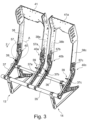
- Figure 3 shows a perspective view of a basic construction of the seat row 1 of the passenger seats 3, 4.
- the basic construction includes in particular a frame and several structural components 38, 38a, 38b, 38c, 41 and 41a.
- a seat divider 37 is preferably arranged on the bars 35 and 36.
- Seat dividers 37b, 37c for the passenger seat 4 are available.
- the seat dividers 37 to 37c have different material recesses.
- the seat dividers 37, 37a, 37b, 37c are preferably constructed the same, in particular identically.
- the seat divider 37 is designed in particular as a flat, angled, for example arcuate component.
- a connecting device 40 according to the invention is arranged at the upper end of the seat divider 37.
- a structural component 38 is advantageously connected to the seat divider 37 via the connecting device 40.
- the structural component 38a is connected to the seat divider 37a via the connecting device 40a.
- the structural component 38b is attached to the seat divider 37b by means of the connecting device 40b and also the structural component 38c is attached to the seat divider 37c by means of the connecting device 40c.
- a connecting structural component 41 is arranged on two structural components 38, 38a.
- the connecting structural component 41 is preferably attached to an upper end of the vertically aligned structural components 38, 38a.
- a connecting structural component 41a is arranged between the vertically aligned structural components 38b and 38c.
- the connecting structural component 41 or 41a preferably acts in a stiffening and/or mechanically stabilizing manner with the two vertical structural components 38 and 38a, or 38b and 38c.
- the connecting structural component 41 and the structural components 38, 38a are connected to one another by means of connecting means (not shown), for example angles and/or screws and/or rivets.
- connecting means not shown
- a one-piece design of the structural components with the connecting structural component is possible. The same applies to the connecting structure component 41a.
- the connecting structural component 41 or 41a is a plate-shaped element with a long and a short Side and a thickness formed.
- the connecting structural component is aligned such that the long side of the connecting structural component 41 or 41a is arranged in the horizontal direction with respect to the passenger seat.
- the three spatial directions width 61, depth 62, height 63 are in Figure 4 shown and relate to the orientation of the seat divider 37 or 37a, or 37b, or 37c.
- the connecting device 40 or 40c is arranged on the right and left on the outside of the seat divider 37 or 37c and on the structural component 38 or 38c.
- the connecting device 40a and 40b is preferably arranged on the centrally arranged seat dividers 37a and 37b.
- the connecting devices 40 and 40c differ from the connecting devices 40a and 40b in the shape of the connecting surfaces 57 and 57c to 57a and 57b.
- the respective outer structural components 38 and 38c also differ in their shape from the respective inner structural components 38a and 38b.
- there is a widening at the upper end of the structural component 38 while the structural component 38a has a widening at the lower end, in the area of the connecting surface 57a.
- a belt connection 39 is arranged on each seat divider 37, 37a, 37b, 37c, in particular all four arranged belt connections 39 are designed in the same way.
- the belt connection 39 is screwed to the seat dividers 37 to 37c; a seat belt with in particular a belt buckle and/or a hook and/or eyelet matched to the belt buckle can advantageously be attached to the belt connection 39.
- FIG 4 is section A Figure 3 shown enlarged.
- the following statements apply to the connecting device 40, but also to the connecting devices 40a to 40c.
- connection device 40 is in Figure 4 shown in an unassembled state of seat divider 37 and structural component 38.
- the connecting device 40 preferably comprises a first plug-in element 42 and a second plug-in element 43.
- the first plug-in element 42 is preferably arranged at the upper end of the seat divider 37, which is aligned towards the structural component 38.
- the first plug-in element 42 is formed in one piece on the seat divider 37, in particular milled out of the material of the seat divider, for example, or produced by milling.
- the first plug-in element 42 has two opposite recesses, which are located on both sides of the separating element 44.
- the recesses are a flat material removal up to a depth T1, in particular both recesses are the same, so that the separating element 44 remains between the recesses.
- the recesses each have a vertically oriented contact surface 56.
- the contact surface 56 is also a boundary surface of the separating element 44; the contact surfaces 56 are preferably designed the same on both sides of the separating element 44.
- the contact surface 56 advantageously has a depth and a height. Both directions are indicated in relation to the orientation of the seat divider or passenger seat.
- the separating element 44 has, for example, an attachment bevel 55 at the upper end.
- the slip-on bevel 55 is preferably formed on an upper end region of the contact surface 56.
- the slip-on bevel 55 is designed in the same way on both sides of the separating element 44, so that the slip-on slopes 55 are aligned roof-shaped on the separating element 44.
- bushings 45 for example designed as screw holes, on the separating element 44.
- bushings 45 are preferably arranged on the contact surface 56, in particular symmetrically, for example according to the corners of a rectangle and/or square.
- a hole 47 which is larger than the bushings 45, is preferably arranged in the middle of the contact surface 56 and is provided, for example, to save weight.
- Each of the contact surfaces 56 is delimited on, for example three sides, surfaces projecting at an angle to the plane of the contact surface 56, for example by two vertically aligned guide surfaces 49 and 50 and a horizontally aligned connecting surface 51.
- the guide surfaces 49 and 50 are elongated and/or strip-shaped, in particular they are aligned vertically in the longitudinal direction.
- the connecting surface 51 is elongated and/or strip-shaped, in particular the connecting surface 51 is aligned horizontally in the longitudinal direction in relation to the passenger seat 3, 4.
- the guide surfaces 49 and 50 and the connecting surface 51 preferably protrude approximately at right angles from the contact surface 56.
- the guide surface 49 is connected to the connecting surface 51 via a concave curvature 54 with z. B. connected to a radius.
- the connecting surface 51 is preferably also connected to the guide surface 50 with a further concave curvature 53 with a, in particular a wider, radius.
- the guide surface 50 is formed at the front of the contact surface 56 when viewed in the seat direction.
- the guide surface 50 is preferably designed approximately vertically or with only a slight deviation from the vertical direction of the passenger seat.
- they are Guide surfaces 49 and 50 are designed differently in their deviation from the vertical direction.
- the rear guide surface 49 is higher than the front guide surface 50.
- the rear guide surface 49 extends over almost the entire height of the contact surface 56, while the front guide surface 50 only extends over a part, in particular approximately half, of the height of the contact surface 56.
- a starting slope 52 is arranged at the upper end of the guide surface 50.
- the approach bevel 52 is preferably designed as a convex curvature, in particular with a radius.
- placing the structural component 38 on the seat divider 37 is simplified by the starting bevel 52 and the slip-on bevels 55 in conjunction with the rear guide edge 51.
- the radius between the front guide surface 50 and the connecting surface 51 is larger than the radius between the rear guide surface 49 and the connecting surface 51. It is also possible the other way around, or for both radii to be the same.
- At least one tongue 48 is arranged on the second plug-in element 43 at the lower end, on the outside of the structural component 38.
- the second plug-in element 43 is constructed from two identical parts, each of which has the tongue 48 and a connecting surface 57.
- the tongues 48 are preferably attached to the structural component 38 at a distance. More preferably, the tongues 48 are designed the same way.
- the outer shape of the tongue 48 is matched to the guide surfaces 49, 50 and the connecting surface 51 in such a way that the border surfaces of the tongue 48 lie on these surfaces 49, 50, 51, and/or the surfaces 49, 50, 51 and the surrounding surfaces of the tongue 48 interact in a form-fitting manner.
- a material recess 58 that is open to the outside on one side is arranged on the tongue 48.
- the material recess 58 advantageously serves to reduce weight.
- a contact surface 56a is arranged on the tongue 48 opposite the material recess; in particular, the side of the tongue is designed as the contact surface 56a, which comes into contact with the contact surface 56 on the first plug-in element 42.
- the contact surface 56 is in flat contact with the contact surface 56a, or the two contact surfaces 56 and 56a are in mutual contact, at least partially.
- a feedthrough 46 preferably several feedthroughs 46 are present.
- the second plug-in element 43 is connected to the structural component 38 at the connection surface 57.
- An upper region 59 which adjoins the tongue 48, for example, preferably has a feedthrough 60.
- several bushings 60 are provided for rivets and/or screws. In Figure 4 No rivets and/or screws and/or other fasteners are shown.
- An advantageous process when joining the two plug-in elements 42 and 43 is as follows:
- the narrow or frontal edge surface of the tongue 48 corresponding to the rear guide surface 49 is guided through the guide surface 49 by a contact when placed.
- the two slip-on bevels 55 allow the position, in particular centering, of the second plug-in element 43 to the first plug-in element 42 to be adjusted in the width direction in relation to the seat divider.
- the starting bevel 52 enables the tongue 48 with the contact surface 56a to be easily fitted onto the contact surface 56.
- the connecting device 40 is shown in the assembled state.
- the second plug-in element 43 is placed on the first plug-in element 42 with the contact surfaces 56 in the area of the contact surface 56a.
- the separating element 44 is arranged, preferably completely, immersed and/or recessed between the two tongues 48.
- the dimensions of the two tongues 48 are selected such that the two tongues 48 can be fitted into the recesses on the first plug-in element 42.
- the tongues 48 fill the recesses on the seat divider 37 exactly or approximately exactly; in particular, tongues 48 are fitted into the recesses in such a way that, from the front in relation to the seat direction, an outer surface of the tongue 48 is flush with an outer surface of the seat divider 37.
- the separating element 44 is designed such that its width is approximately 50% of the width of the seat divider.
- the guide surfaces 49 and 50 and the connecting surface 51 each have a width of approximately 25% of the width of the seat divider 37.
- the width of the tongue 48 is matched to the width of the guide surfaces or the width of the recess on the seat divider 37. In particular, the width of the tongue 48 is approximately 25% of the width of the seat divider 37.
- the connecting device 40a differs from the connecting device 40a only in the connection surface 57 or 57a.
- the remaining features are corresponding. ⁇ u>Reference symbol list ⁇ /u> 1 row of seats 36 rear spar 2 Seating direction 37 Seat divider 3 Passenger seat 37a Seat divider 4 Passenger seat 37b Seat divider 5 Seat bottom 37c Seat divider 6 backrest 38 Structural component 7 Enclosure 38a Structural component 8th Leg rest 38b Structural component 9 Seat bottom 38c Structural component 10 backrest 39 Belt connection 11 Enclosure 40 Connection device 12 Leg rest 40a Connection device 13 Support leg 40b Connection device 14 Support leg 40c Connection device 15 strut 41 Connecting structure component 16 End area 17 Assembly site 41a Connecting structure component 18 strut 19 End area 42 first plug-in element 20 Assembly site 43 second plug-in element 21 Bracing element 44 Separator 22 strut 45 execution 23 End area 46 execution 24 Assembly site 47 Hole 25 strut 48 Tongue 26 End area 49 Guide surface 27 Assembly site
Description
- Die Erfindung betrifft einen Fluggastsitz mit einer Verbindungsvorrichtung sowie eine Sitzreihe gebildet aus mehreren solcher Fluggastsitze.
- Zur Ausstattung von Passagierflugzeugen sind Fluggastsitze oder Sitzreihen aus mehreren nebeneinander angeordneten Fluggastsitzen bekannt. Die Fluggastsitze können eine Vielzahl von Ausführungsformen aufweisen. Fluggastsitze sind beispielsweise aus der
EP 3 459 852 A1 oder derUS 2017/0297456 A1 bekannt. DieDE 10 2008 020 156 A1 zeigt einen bekannten Fahrzeugsitz. - Alle Fluggastsitze müssen Sicherheitsrichtlinien entsprechen. Gleichzeitig sollen die Sitze ein möglichst geringes Gewicht aufweisen. Außerdem ist eine kompakte Außenform erwünscht.
- Der Fluggastsitz sollte derart aufgebaut sein, dass er in den Sicherheitsrichtlinien vorgesehenen Tests, insbesondere Crash-Tests besteht. Hierzu sind stabile Verbindungen zwischen verschiedenen Bauteilen des Fluggastsitzes notwendig.
- Beispielsweise ist am Fluggastsitz ein Sicherheitsgurt vorhanden. Der Sicherheitsgurt ist bevorzugt als Beckengurt ausgebildet und z.B. mit einem Gestell und/oder einem Sitzteiler des Fluggastsitzes an zum Beispiel zwei Gurtanbindungspunkten verbunden.
- Aufgabe der vorliegenden Erfindung ist es, einen verbesserten Fluggastsitz mit erhöhter Stabilität bereitzustellen.
- Die Aufgabe wird durch die Merkmale des unabhängigen Anspruchs 1 gelöst.
- In den abhängigen Ansprüchen sind zweckmäßige und vorteilhafte Varianten und Ausführungsformen der Erfindung angegeben.
- Nachfolgend werden alle Richtungen in Bezug zu einer Sitzrichtung angegeben, wobei unter der Sitzrichtung die Richtung zu verstehen ist, in welcher ein Fluggast blickt, wenn er in dem Fluggastsitz sitzt.
- Die Erfindung geht aus von einem Fluggastsitz mit einem Gestell, das zur Befestigung an einem Boden einer Fluggastkabine vorgesehen ist, wobei das Gestell einen Sitzteiler und quer zur Sitzrichtung verlaufende Holme umfasst, wobei der Sitzteiler durch die Holme gehalten ist, wobei eine Umhausung mit einem Strukturbauteil vorgesehen ist, wobei die Umhausung eine Rückenlehne zumindest teilweise umgibt.
- Vorzugsweise umfasst der Fluggastsitz eine Kopfstütze, eine Rückenlehne, einen Sitzboden und eine Beinauflage. Diese zum Beispiel vier wesentlichen Teile des Fluggastsitzes sind bevorzugt über Beschläge und/oder Gelenke miteinander verbunden, vorteilhafterweise einstellbar, insbesondere gegeneinander verstellbar.
- Mit unten wird der Boden der Fluggastkabine bezeichnet, während oben eine entgegengesetzte Position bezeichnet, welche insbesondere vertikal beabstandet zu unten ist.
- Bevorzugterweise sind das Strukturbauteil, der Sitzteiler und die Holme aus einem Metallmaterial, vorteilhafterweise aus Aluminium, einem anderen leichten und stabilen Material, und/oder zum Beispiel aus einem Verbundwerkstoff, insbesondere aus einem Kohlefaserverbundwerkstoff hergestellt. Vorteilhafterweise sind alle Bauteile des Fluggastsitzes im Hinblick auf ihre Materialien und das damit verbundene Gewicht optimiert. Insbesondere ist auch die Form der Bauteile hinsichtlich des Gewichts optimiert, so dass die Bauteile zum Beispiel gezielt gewählte Materialausnehmungen aufweisen, welche zu einer Gewichtsersparnis des jeweiligen Bauteils beitragen.
- Der Fluggastsitz ist mit dem Gestell am Boden einer Fluggastkabine anordenbar. Das Gestell umfasst den Sitzteiler und quer zur Sitzrichtung verlaufende Holme, wobei ein erster vorderer Holm und ein zweiter, in Sitzrichtung gesehen, dahinter angeordneter Holm vorhanden sind. Vorzugsweise sind beide Holme am Sitzteiler angeordnet. Vorteilhafterweise verlaufen die zwei Holme beabstandet, insbesondere mehrheitlich parallel zueinander.
- Der Sitzteiler ist als ein mechanisch stabiles Bauteil des Fluggastsitzes ausgebildet. Insbesondere ist der Sitzteiler dazu ausgelegt, Kräfte welche bei einem Crash auf den Fluggastsitz wirken, aufzunehmen und/oder in Richtung des Bodens der Fluggastkabine zu leiten.
- Der Sitzteiler weist in Sitzrichtung gesehen eine Höhe, eine Breite und eine Tiefe auf. Die Breite des Sitzteilers ist bevorzugt kleiner als die Tiefe des Sitzteilers. Beispielsweise ergibt sich die Höhe des Sitzteilers aus einer Abmessung in vertikaler Richtung in Bezug zum Fluggastsitz. Bevorzugt beträgt die Höhe des Sitzteilers ein Vielfaches der Breite und/oder der Tiefe des Sitzteilers.
- Am Sitzteiler ist die Umhausung fest angeordnet. Die Umhausung umfasst das Strukturbauteil. Die Umhausung umgibt zumindest teilweise die Rückenlehne des Fluggastsitzes.
- Der Fluggastsitz umfasst die Umhausung, welche im Bereich der Rückenlehne angeordnet ist. Die Rückenlehne ist im Bereich der Umhausung, relativ zur Umhausung verstellbar. Beispielsweise ist die Rückenlehne im Bereich der Umhausung relativ zur Umhausung beweglich geführt. Bevorzugterweise ist die Umhausung feststehend in der Fluggastkabine vorhanden, z.B. positionsfest und insbesondere nicht beweglich bei der Verstellung der Rückenlehne. In einer vorteilhaften Ausführungsvariante ist die Umhausung am Sitzteiler anordenbar. Bevorzugt verdeckt die Umhausung das Strukturbauteil, welches zum Beispiel innerhalb der Umhausung angeordnet ist. Beispielsweise ist die Umhausung schalenförmig und/oder u-förmig ausgebildet.
- Bevorzugt sind pro Fluggastsitz zwei Sitzteiler vorhanden. Beispielsweise sind die beiden Sitzteiler beabstandet voneinander angeordnet. Bevorzugt sind die beiden Sitzteiler parallel zueinander angeordnet. Vorteilhafterweise sind zwei Ebenen, jeweils aufgespannt aus der Höhe und der Tiefe des Sitzteilers, zumindest annähernd, parallel zueinander angeordnet. Insbesondere wird der Fluggastsitz an beiden Seiten, insbesondere außen, durch die Sitzteiler begrenzt, vorteilhafterweise im Bereich des Sitzbodens. Bevorzugterweise ist der Sitzteiler derart mechanisch belastbar ausgeführt, dass beispielsweise am Sitzteiler die Gurtanbindungspunkte für den Sicherheitsgurt des Fluggasts anordenbar sind, z.B. anschraubbar sind.
- Am Sitzteiler ist in einer vorteilhaften Ausführungsform das Strukturbauteil angeordnet. Beispielsweise ist das Strukturbauteil oberhalb an den Sitzteiler anschließend angeordnet. Insbesondere weist das Strukturbauteil eine Breite, eine Höhe und eine Tiefe auf. Bevorzugt ist das Strukturbauteil streifenförmig ausgebildet, z.B. ist die Höhe ein Vielfaches der Tiefe und/oder der Breite des Strukturbauteils.
- Der Kern der Erfindung ist, dass der Sitzteiler mit dem Strukturbauteil über eine Verbindungsvorrichtung verbunden ist, wobei die Verbindungsvorrichtung als eine Steckverbindung ausgebildet ist.
- Bevorzugterweise ist die Verbindungsvorrichtung als die Steckverbindung ausgebildet. Durch die Verbindungsvorrichtung wird vorteilhafterweise eine sehr stabile Verbindung zwischen dem Sitzteiler und dem Strukturbauteil erreicht. Insbesondere ist die Verbindungsvorrichtung dazu vorgesehen Kräfte, welche bei einem Crash entstehen können, aufzunehmen und/oder über den Sitzteiler auf das Stützbein und/oder den Kabinenboden zu übertragen. Weiter ermöglicht die Verbindungsvorrichtung einen einfachen und/oder schnellen Zusammenbau aus mehreren Teilen bei der Montage des Fluggastsitzes. Vorteilhafterweise sind die Sitzteiler und die Strukturbauteile separat vormontierbare Bauteile des Fluggastsitzes.
- In einer vorteilhaften Ausführungsform ist an jedem Sitzteiler des Fluggastsitzes die Verbindungsvorrichtung, insbesondere die Steckverbindung angeordnet.
- In einer vorteilhaften Ausgestaltung wird das Strukturbauteil von der Umhausung, zumindest teilweise verdeckt. Die Umhausung ist in einer vorteilhaften Ausführungsform aus Kunststoff hergestellt. So kann beinahe jede beliebige Form der Umhausung realisiert werden. Durch die Umhausung ergibt sich beispielsweise ein angenehmeres Sitzen auf einem dahinter angeordneten Fluggastsitz. Ein dort sitzender Fluggast wird vorteilhafterweise durch eine Verstellung der Rückenlehne des in Sitzrichtung gesehenen vorderen Fluggastsitzes nicht wesentlich beeinträchtig oder gestört, da die Umhausung vorteilhafterweise positionsfest ausgeführt ist.
- In einer vorteilhaften Ausführungsform umfasst die Verbindungsvorrichtung ein erstes Steckelement und ein zweites Steckelement, wobei das erste Steckelement am Sitzteiler angeordnet ist und das zweite Steckelement am Strukturbauteil angeordnet ist.
- Vorteilhafterweise umfasst die Steckverbindung das erste und das zweite Steckelement. Beispielsweise ist das erste Steckelement einstückig am und/oder aus dem oberen Ende des Sitzteilers angeordnet, insbesondere gebildet. Insbesondere wird das erste Steckelement aus dem Material des Sitzteilers gebildet und/oder ausgeformt, zum Beispiel ausgefräst. Alternativ ist das erste Steckelement an dem oberen Ende des Sitzteilers anbringbar, insbesondere anschraubbar, und/oder annietbar.
- Vorteilhafterweise ist das zweite Steckelement am Strukturbauteil angeordnet. Insbesondere ist das zweite Steckelement am Strukturbauteil fixiert, bevorzugt unlösbar, zum Beispiel mittels Niete. In einer weiteren Ausführungsvariante ist das zweite Steckelement zum Beispiel aus dem Strukturbauteil gebildet und/oder ausgeformt und/oder einstückig am Strukturbauteil angeordnet.
- Bevorzugterweise ist die Verbindungsvorrichtung als eine Art Nut-und-Feder-Verbindung ausgebildet.
- Insbesondere ist die Steckverbindung als eine Art Nut-und-Feder-Verbindung ausgebildet. Beispielsweise ist das erste Steckelement als eine Feder der Nut-und-Feder-Verbindung ausgebildet. Bevorzugt handelt es sich beim ersten Steckelement, ausgebildet als die Feder, um ein Trennelement, welches vorteilhafterweise eine abgeschrägte Aufsteck-Fläche, zum Beispiel ausgebildet als Fase, aufweist. Vorteilhafterweise ist das zweite Steckelement als eine Art Nut in der Nut-und-Feder-Verbindung ausgebildet. Beispielsweise umfasst das zweite Steckelement eine Öffnung, insbesondere eine schlitzartige Ausnehmung, vorteilhafterweise eine Nut. Bevorzugt wird die Nut von gegenüberliegenden Wänden bzw. Wangen gebildet und/oder begrenzt.
- Weiter bevorzugt ist das erste Steckelement im zweiten Steckelement anordenbar, insbesondere wenn es sich um die Nut-Feder-Verbindung handelt. Bevorzugterweise ist das erste Steckelement im zweiten Steckelement einsteckbar, insbesondere vollständig einsteckbar, und/oder versenkbar, insbesondere komplett versenkbar.
- In einer bevorzugten Ausführungsvariante ist das erste Steckelement am Sitzteiler angeordnet, wobei das erste Steckelement eine Ausnehmung umfasst, wobei die Ausnehmung in Sitzrichtung gesehen eine Tiefe von mindestens 50% der Tiefe des Sitzteilers aufweist.
- Vorteilhafterweise umfasst das erste Steckelement die Ausnehmung. Bevorzugt ist das erste Steckelement mit der Ausnehmung im oberen Bereich des Sitzteilers angeordnet, insbesondere am oberen Ende. Bevorzugt ist auf beiden Seiten des ersten Steckelements jeweils eine Ausnehmung angeordnet. Insbesondere sind die zwei Ausnehmungen gegenüberliegend angeordnet. Vorteilhafterweise ist zwischen den Ausnehmungen das Trennelement angeordnet, insbesondere grenzen die Ausnehmungen auf beiden Seiten an das Trennelement an. Beispielsweise beträgt die Ausnehmung 50%, 60%, 70%, 80%, 85%, 90%, 95%, 99%, 100% der Tiefe des Sitzteilers, in Sitzrichtung gesehen. Insbesondere sind auch weitere, beliebige Werte zwischen 50% und 100% möglich. Vorteilhafterweise ist eine Höhe der Ausnehmung ungefähr genauso groß wie die Tiefe der Ausnehmung. Zum Beispiel weist die Ausnehmung eine Breite auf, welche insbesondere 10% bis 40%, bevorzugt 25% der Breite des Sitzteilers entspricht. Bevorzugt ergeben zwei Ausnehmungen zusammen eine Breite zwischen 20% und 80%, bevorzugt 50% der Breite des Sitzteilers, insbesondere sind auch weitere beliebige Werte zwischen 20% und 80% möglich. Vorteilhafterweise sind die Ausnehmungen auf den beiden Seiten des Sitzteilers ähnlich, insbesondere gleich ausgeführt. Auf Grund der vorteilhaften Ausgestaltung mit gegenüberliegenden Ausnehmungen, ergibt sich ein Bereich zwischen den beiden Ausnehmungen, das Trennelement, der ebenfalls ca. 50% der Breite des Sitzteilers entspricht. Beispielsweise beträgt die Breite des Trennelements Werte zwischen 20% und 80% der Breite des Sitzteilers. Vorteilhafterweise entspricht die Breite von zwei Ausnehmungen und die Breite des Trennelements der Breite des Sitzteilers.
- Vorteilhafterweise umfasst das Trennelement eine Durchführung, zum Beispiel ein Loch. Mittels der Durchführung, ausgebildet z.B. als Schraubloch, ist die Steckverbindung im angeordneten Zustand der beiden Steckelemente fixierbar. Bevorzugt sind mehrere, insbesondere vier Durchführungen in den beiden Steckelementen zur Fixierung vorhanden. Vorteilhafterweise ist am Trennelement eine weitere Öffnung, insbesondere als größeres Loch angeordnet. Beispielsweise ist das größere Loch zur Materialersparnis und somit zur Gewichtsreduktion des Bauteils vorgesehen.
- In einer bevorzugten Ausführungsform umfasst das zweite Steckelement eine Zunge. Vorteilhaft ist die Zunge am zweiten Steckelement ausgebildet, insbesondere einstückig. In einer bevorzugten Ausführungsvariante umfasst das zweite Steckelement mehrere Abschnitte, insbesondere zwei Abschnitte. Beispielsweise sind ein oberer Abschnitt und ein unterer Abschnitt vorhanden. Zum Beispiel ist der obere Abschnitt als eine Anbindungsfläche an das Strukturbauteil ausgebildet. Insbesondere ist der untere Abschnitt des zweiten Steckelements als die Zunge ausgebildet. Beispielsweise ist die Zunge an der Ausnehmung des ersten Steckelements am Sitzteiler anordenbar. Bevorzugt ist die Zunge als Gegenstück zum ersten Steckelement ausgebildet. Insbesondere sind beide Steckelemente derart ausgebildet, dass sie formschlüssig zusammen wirken. Bevorzugterweise bilden die beiden Steckelemente im angeordneten Zustand einen Steckzustand. Die Zunge weist eine Höhe auf, welche vorteilhafterweise der Höhe der Ausnehmung des ersten Steckelements am Sitzteiler entspricht. Die sich im Steckzustand berührenden Flächen der beiden Steckelemente, z.B. die Ausnehmung des ersten Steckelements und eine Seitenfläche der Zunge sind Kontaktflächen des ersten und/oder zweiten Steckelements.
- In einer vorteilhaften Ausführungsform umfasst das erste Steckelement genau eine Ausnehmung und das zweite Steckelement genau eine Zunge. Bevorzugterweise bilden die genau eine Ausnehmung und die genau eine Zunge die Verbindungsvorrichtung, insbesondere die Steckverbindung.
- Bevorzugt umfasst das zweite Steckelement zwei Zungen, wobei die Zungen beabstandet voneinander am Strukturbauteil angeordnet sind. Insbesondere wird der Abstand der beiden Zungen bestimmt durch die Breite des Strukturbauteils an einer Anbindungsstelle. Vorzugsweise wird die Art Nut der Nut-und-Feder-Verbindung durch den Freiraum zwischen zwei Zungen gebildet.
- In einer vorteilhaften Ausführungsform weist die Zunge eine Höhe auf, welche 50% bis 150% der Tiefe der Ausnehmung am ersten Steckelement beträgt. Beispielsweise beträgt die Höhe der Zunge 30% bis 200% der Tiefe der Ausnehmung, vorzugsweise 75% bis 125%, insbesondere 100% der Tiefe der Ausnehmung.
- Vorteilhaft weisen die beiden Zungen zusammen eine Breite von ungefähr 50% der Breite des Sitzteilers auf. Insbesondere weist jede Zunge für sich eine Breite zwischen 10% und 40% der Breite des Sitzteilers auf, insbesondere 25% der Breite des Sitzteilers.
- Bevorzugt weist das zweite Steckelement eine Höhe zwischen 150% und 500% der Höhe der Zunge, beispielsweise 200% bis 400%, bevorzugt 300% auf.
- Vorteilhafterweise umfasst das erste Steckelement eine Führungsfläche. Beispielsweise ist die Führungsfläche als ein im Vergleich zur Fläche der Ausnehmung überstehender Bereich ausgebildet. Insbesondere ist die Führungsfläche eine Begrenzung der Fläche der Ausnehmung. Vorteilhafterweise steht die Führungsfläche winklig von der Fläche der Ausnehmung ab. Die Fläche der Ausnehmung ist im Steckzustand die Kontaktfläche des ersten Steckelements.
- In einer bevorzugten Ausführungsform umfasst das erste Steckelement mehrere Führungsflächen, insbesondere zwei, welche gegenüberliegend zueinander ausgebildet sind. Beispielsweise sind die zwei gegenüberliegenden Führungsflächen annähernd vertikal ausgebildet, bezogen auf die Ausrichtung des Fluggastsitzes. Vorteilhafterweise sind die zwei Führungsflächen als eine vordere Führungsfläche und eine hintere Führungsfläche ausgebildet, wobei die Richtung in Bezug zur Sitzrichtung gewählt ist. Bevorzugterweise ist die in Sitzrichtung gesehen, hintere Führungsfläche derart ausgebildet, dass die hintere Führungsfläche von dem unteren Ende des ersten Steckelements bis zum oberen Ende des ersten Steckelements sich erstreckt. Vorteilhaft gleitet an der hinteren Führungsfläche das zweite Steckelement beim Zusammenfügen der Verbindungsvorrichtung entlang.
- Weiter bevorzugt ist die in Sitzrichtung gesehene, vordere Führungsfläche schräg, insbesondere winklig zur Verbindungsfläche, ausgebildet. Hierdurch ergibt sich vorteilhaft, dass das zweite Steckelement beim Zusammenfügen der Steckverbindung an dieser Führungsfläche entlang geführt wird, insbesondere entlang gleitet. Beispielsweise ist am oberen Ende der vorderen Führungsfläche eine Anlaufschräge in Form einer Krümmung mit einem Radius vorhanden, wobei die Anlaufschräge das Zusammenfügen der Steckverbindung erleichtert.
- In einer vorteilhaften Ausführungsvariante weisen die zwei Steckelemente im angeordneten Zustand ungefähr die gleiche Breite wie der Sitzteiler auf. Bevorzugt weisen die zwei Steckelemente im zusammengefügten Zustand eine Breite auf, welche ungefähr gleich ist, wie die Breite des Sitzteilers. Vorteilhafterweise weisen die beiden Steckelemente im Steckzustand eine Breite gleich der Breite des Sitzteilers auf.
- In einer vorteilhaften Ausführungsform weist das erste Steckelement im Bereich der Ausnehmung eine Breite von 10% bis 80%, insbesondere 50% der Breite des Sitzteilers auf. Bevorzugt weist das erste Steckelement zwei gegenüberliegende Ausnehmungen auf. Diese beiden Ausnehmungen entsprechen z.B. zusammen ungefähr der Hälfte der Breite des Sitzteilers. Insbesondere entspricht jede Ausnehmung zwischen 10% und 40% der Breite des Sitzteilers, bevorzugt 25%. Bevorzugt ergibt sich die Breite des Trennelements aus der Breite des ersten Steckelements, insbesondere der Breite des Sitzteilers unterhalb der Ausnehmung, abzüglich der Breite der beiden Ausnehmungen.
- Bevorzugterweise umfasst das erste Steckelement ein oberes und ein unteres Ende, wobei das obere Ende mindestens eine abgeschrägte Aufsteck-Fläche umfasst und das untere Ende eine zur Fläche der Ausnehmung abstehende Fläche ist. Vorteilhaft ist das obere Ende als eine Aufsteck-Schräge ausgebildet. Bevorzugt ist das obere Ende an beiden Seiten als jeweils eine abgeschrägte Aufsteck-Fläche, zum Beispiel eine Fase, ausgebildet. Insbesondere sind die beiden Aufsteck-Flächen winklig zueinander angeordnet, zum Beispiel dachförmig. Beispielsweise sind die abgeschrägten Aufsteck-Flächen am obersten Ende des ersten Steckelements näher zusammen als in Richtung des unteren Endes der Ausnehmung.
- In einer vorteilhaften Ausführungsform umfasst das erste Steckelement an seinem unteren Ende der Ausnehmung eine Verbindungsfläche. Bevorzugterweise ist die Verbindungsfläche als eine zur Fläche der Ausnehmung abstehende Fläche ausgebildet. Bevorzugt ist die Verbindungsfläche horizontal ausgerichtet, insbesondere annähernd parallel zum Boden der Fluggastkabine ausrichtbar. Vorteilhafterweise sind die zwei gegenüberliegenden Führungsflächen durch die Verbindungsfläche miteinander verbunden. Bevorzugterweise sind eine der Führungsflächen und die angrenzende Verbindungsfläche durch eine Krümmung verbunden, vorteilhaft ausgebildet als Kreisabschnitt, insbesondere mit einem Radius. Insbesondere sind die zwei Führungsflächen mit der Verbindungsfläche mit zwei verschiedenen Radien miteinander verbunden. Möglich sind auch zwei gleiche Radien. Besonders bevorzugt ist ein im Vergleich zum anderen Radius größerer Radius in der vorderen Krümmung und ein entsprechend kleinerer Radius an der hinteren Krümmung, in Sitzrichtung gesehen, vorhanden.
- In einer bevorzugten Ausführungsform mit verschiedenen Radien und vertikalen Führungsfläche mit einer, insbesondere kleinen Abweichung von der vertikalen Ausrichtung, ergibt sich eine vertauschsichere Ausgestaltung der Verbindungsvorrichtung, insbesondere eine fehlersichere Ausgestaltung der Steckverbindung. Vorteilhafterweise ist eine Fixierung der Steckverbindung nur in einer korrekten Position der Steckelemente ineinander möglich. Vorteilhafterweise erfolgt durch die Aufsteck-Schrägen am oberen Ende des ersten Steckelements eine Positionierung des zweiten Steckelements während des Zusammenfügens in Richtung der Breite der Steckverbindung bzw. in Richtung der Breite des Sitzteilers. Weiter ergibt sich durch die beiden Führungsflächen eine weitere Positionierung des zweiten Steckelements relativ zum ersten Steckelement beim Zusammenfügen in Richtung der Tiefe der Steckelemente bzw. in Richtung der Tiefe des Sitzteilers.
- Bevorzugt weist das Strukturbauteil eine horizontale Fläche auf. Insbesondere ist die horizontale Fläche ein unteres Ende des Strukturbauteils. Beispielsweise ergibt sich die horizontale Fläche aus der Breite und der Tiefe des Strukturbauteils. Vorzugsweise ist die horizontale Fläche des Strukturbauteils annähernd parallel zum oberen Ende des ersten Steckelements ausgeführt.
- In einer weiteren vorteilhaften Ausgestaltung weist das Strukturbauteil am unteren Ende, insbesondere im Bereich der horizontalen Fläche, eine überstehende Nase auf. Die überstehende Nase ist aus dem Strukturbauteil ausgeformt und/oder einstückig aus dem Strukturbauteil herstellbar. Ebenso ist es möglich die Nase mittels z.B. Schrauben und/oder Niete am Strukturbauteil zu fixieren. Beispielsweise ist die überstehende Nase in Sitzrichtung vor der Verbindungsvorrichtung am Strukturbauteil angeordnet.
- In einer bevorzugten Ausführungsvariante weist das zweite Steckelement eine Anbindungsfläche auf, mit welcher das zweite Steckelement am Strukturbauteil angeordnet ist. Bevorzugt sind im Bereich der Anbindungsfläche Durchführungen für Niete und/oder Schrauben zur Anordnung, insbesondere zur Befestigung am Strukturbauteil vorhanden. Beispielsweise ist die Anbindungsfläche zur Fixierung am Strukturbauteil ausgebildet. Vorteilhafterweise handelt es sich bei der Anbindungsfläche um den oberen Abschnitt des zweiten Steckelements, bevorzugt beabstandet zur Zunge am zweiten Steckelement angeordnet. In einer vorteilhaften Ausführung grenzt die Zunge an die Anbindungsfläche an.
- Bevorzugt weist das zweite Steckelement zwei Teile auf, welche z.B. jeweils aus einer Zunge und einer Anbindungsfläche gebildet sind.
- Bevorzugterweise umfasst eine Sitzreihe mindestens zwei Fluggastsitze nach einer der vorhergehenden Ausgestaltungsmöglichkeiten. Beispielsweise sind in einer Sitzreihe zwei der oben beschriebenen Fluggastsitze angeordnet, insbesondere als Flugastsitz-Paar. Vorteilhafterweise ist das Fluggastsitz-Paar derart angeordnet, dass zwei Stützbeine, welche mit dem Kabinenboden, insbesondere mit Halterungen im Kabinenboden verbindbar sind, ausreichend sind. Beispielsweise sind die Stützbeine mit dem Holm miteinander verbunden, bevorzugt sind zwei Holme vorhanden. In einer vorteilhaften Variante werden die Stützbeine mittels einer Scheibennabenverbindung am Holm fixiert. Ebenso vorteilhaft sind die Sitzteiler an den Holmen anordenbar, so dass sich die Sitzreihe bilden lässt. Bevorzugt umfasst das Fluggastsitz-Paar vier Sitzteiler mit vier Verbindungsvorrichtungen, zur Anbindung von vier Strukturbauteilen.
- Weitere vorteilhafte Merkmale, Ausgestaltungen, Varianten und Ausführungsformen sind anhand eines schematischen Ausführungsbeispiels näher erläutert.
- Im Einzelnen zeigt:
- Figur 1
- in einer perspektivischen Ansicht schräg von vorne eine Sitzreihe mit zwei Fluggastsitzen jeweils umfassend einen Sitzboden, eine Rückenlehne samt rückseitiger Umhausung und eine Beinauflage,
- Figur 2
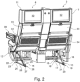
- die Sitzreihe gemäß
Figur 1 in einer perspektivischen Ansicht von schräg hinten, - Figur 3
- ein Teil eines Gestells und mehrere Strukturbauteile der Sitzreihe aus
Figur 1 in einer perspektivischen Ansicht von schräg vorne, - Figur 4
- die erfindungsgemäße Verbindungsvorrichtung in einer Detailansicht A aus
Figur 3 in schräg seitlicher Ansicht, - Figur 5
- die Verbindungsvorrichtung aus
Figur 4 in einem zusammengefügten Zustand in seitlich in schräg seitlicher Ansicht. - Für einen nutzbaren, funktionsfähigen Fluggastsitz sind weitere Bauteile notwendig, welche in den
Figuren 3 bis 5 nicht dargestellt sind. Es wird nur auf die für die Verbindungsvorrichtung notwendigen Bauteile eingegangen. -
Figur 1 zeigt eine Sitzreihe 1 mit einer Sitzrichtung 2 mit zwei Fluggastsitzen 3 und 4. Nachfolgend beziehen sich Positions- und Richtungsangaben wie vorne, hinten, oben und unten auf die Sitzrichtung 2 und den Nutzzustand der Sitzreihe 1. - Beide Fluggastsitze 3 und 4 sind entsprechend aufgebaut. Der Fluggastsitz 3 weist einen Sitzboden 5, eine Rückenlehne 6 und eine zur Rückenlehne 6 rückseitige Umhausung 7 auf. Im Anschluss an einen vorne liegenden Endbereich des Sitzbodens 5 ist eine vorzugsweise klappbare Beinauflage 8 vorhanden, die um eine horizontale Achse klappbar ist.
- Dementsprechend umfasst der Fluggastsitz 4 einen Sitzboden 9, eine Rückenlehne 10, eine Umhausung 11 und eine Beinauflage 12.
- Die Sitzboden 5, 9, die Rückenlehnen 6, 10 und die Beinauflagen 8, 12 umfassen eine vorzugsweise ergonomisch geformte Polsterung.
- Die Fluggastsitze 3 und 4 sind über zwei Stützbeine 13 und 14 an einem Kabinenboden einer Flugkabine eines dazugehörigen Flugzeuges montierbar.
- Das Stützbein 13 weist hierfür an einem unteren Endbereich 16 einer vorderen Strebe 15 eine Montagestelle 17 und eine weitere Montagestelle 20 an einem unteren Endbereich 19 einer hinteren Strebe 18 auf. Zwischen den Endbereichen 16 und 19 ist ein Verstrebungselement 21 vorgesehen.
- Das Stützbein 14 weist an einem unteren Endbereich 23 einer vorderen Strebe 22 eine Montagestelle 24 und eine weitere Montagestelle 27 an einem unteren Endbereich 26 einer hinteren Strebe 25 auf. Zwischen den Endbereichen 23 und 26 ist ein Verstrebungselement 28 vorgesehen.
- Die Sitzreihe 1 weist zudem eine äußere Armlehne 29 seitlich am Fluggastsitz 3 und eine äußere Armlehne 30 seitlich am Fluggastsitz 4 auf. Zwischen den beiden Fluggastsitzen 3 und 4 ist vorzugsweise auf Höhe der beiden äußeren Armlehnen 29 und 30 eine Konsole 31 vorhanden, welche von einem Fluggast ebenfalls als Armauflage genutzt werden kann.
- In einer Schalenform der jeweiligen Umhausung 7 bzw. 11 ist die jeweils dazugehörige Rückenlehne 6 bzw. 10 angeordnet. Die Rückenlehne 6 bzw. 10 ist vorzugsweise zur Einstellung von unterschiedlichen Kippstellungen beweglich in der Umhausung 7 bzw. 11 geführt, beispielsweise zusammen mit dem dazugehörigen verschiebbar gelagerten Sitzboden 5 bzw. 9.
- Die Umhausungen 7 und 11 sind mit weiteren Elementen versehen, z. B. rückseitig jeweils mit Zusatzfunktionen versehen. In einem oberen rückseitigen Bereich der Umhausungen 7, 11 ist beispielsweise jeweils eine Multimedia-Einheit 32 für digitale Medien vorgesehen, zum Beispiel mit einem elektronischen Ein- und Ausgabegerät bzw. mit einem Touchscreen.
- In einem unterhalb an die Multimedia-Einheit 32 anschließenden bzw. mittleren Bereich ist zum Beispiel jeweils ein klappbares Ablageelement 33 wie ein Tablett-Tisch mit einer Tischplatte ausgebildet. In
Fig. 2 sind die Ablageelemente 33 in einer nach oben herangeklappten, vertikal stehenden und gesicherten Nichtnutzungsstellung dargestellt. - Unterhalb des jeweiligen klappbaren Ablageelements 33 ist ein Staufach 34 beispielswiese zur Unterbringung von Zeitschriften bzw. Prospekten oder anderen Gegenständen vorhanden.
-
Figur 3 zeigt eine perspektivische Ansicht einer Grundkonstruktion der Sitzreihe 1 der Fluggastsitze 3, 4. Die Grundkonstruktion umfasst insbesondere ein Gestell und mehrerer Strukturbauteile 38, 38a, 38b, 38c, 41 und 41a. - Beispielsweise sind am Gestell, welches die Stützbeine 13, 14, umfasst, zwei Holme 35, 36 angeordnet. Vorteilhafterweise sind der vordere Holm 35 und der hintere Holm 36 annäherungsweise parallel zueinander ausgerichtet. Bevorzugt ist an den Holmen 35 und 36 ein Sitzteiler 37 angeordnet. Bevorzugterweise sind zwei Sitzteiler 37, 37a für den Fluggastsitz 3 und die weiteren Sitzteiler 37b, 37c für den Fluggastsitz 4 vorhanden. Insbesondere weisen die Sitzteiler 37 bis 37c verschiedenen Materialausnehmungen auf. Die Sitzteiler 37, 37a, 37b, 37c sind vorzugsweise gleich, insbesondere identisch aufgebaut. Der Sitzteiler 37 ist insbesondere als flaches, winkliges, beispielsweise bogenförmiges Bauteil ausgeführt. Beispielsweise ist am oberen Ende des Sitzteilers 37 eine erfindungsgemäße Verbindungsvorrichtung 40 angeordnet.
- Vorteilhafterweise ist über die Verbindungsvorrichtung 40 ein Strukturbauteil 38 an den Sitzteiler 37 angebunden. Ebenso ist über die Verbindungsvorrichtung 40a das Strukturbauteil 38a an den Sitzteiler 37a angebunden. Weiter ist mittels der Verbindungsvorrichtung 40b das Strukturbauteil 38b an den Sitzteiler 37b angebracht und ebenso das Strukturbauteil 38c mittels der Verbindungsvorrichtung 40c an den Sitzteiler 37c.
- In der dargestellten Ausführungsform ist zum Beispiel an zwei Strukturbauteile 38, 38a ein Verbindungsstrukturbauteil 41 angeordnet. Bevorzugt ist das Verbindungsstrukturbauteil 41 an einem oberen Ende der vertikal ausgerichteten Strukturbauteile 38, 38a angebracht. Ein Verbindungsstrukturbauteil 41a ist zwischen den vertikal ausgerichteten Strukturbauteilen 38b und 38c angeordnet. Vorzugsweise wirkt das Verbindungsstrukturbauteil 41 bzw. 41a aussteifend und/oder mechanisch stabilisierend mit den beiden vertikalen Strukturbauteilen 38 und 38a, bzw. 38b und 38c zusammen. Beispielsweise sind das Verbindungsstrukturbauteil 41 und die Strukturbauteile 38, 38a mittels Verbindungsmitteln (nicht dargestellt), z.B. Winkeln und/oder Schrauben und/oder Niete miteinander verbunden. Alternativ ist eine einstückige Ausbildung der Strukturbauteile mit dem Verbindungsstrukturbauteil möglich. Für das Verbindungsstrukturbauteil 41a gilt entsprechendes.
- Vorzugsweise ist das Verbindungsstrukturbauteil 41 bzw. 41a als ein plattenförmiges Element mit einer langen und einer kurzen Seite und einer Dicke ausgebildet. Beispielsweise ist das Verbindungsstrukturbauteil derart ausgerichtet, dass die lange Seite des Verbindungsstrukturbauteils 41 bzw. 41a in der horizontalen Richtung bezogen auf den Fluggastsitz angeordnet ist.
- Die drei Raumrichtungen Breite 61, Tiefe 62, Höhe 63 sind in
Figur 4 dargestellt und beziehen sich auf die Ausrichtung des Sitzteilers 37 bzw. 37a, bzw. 37b, bzw. 37c. - Beispielsweise ist gemäß Darstellung in
Figur 3 , jeweils rechts, bzw. links außen an dem Sitzteiler 37 bzw. 37c und am Strukturbauteil 38 bzw. 38c die Verbindungsvorrichtung 40 bzw. 40c angeordnet. Vorzugsweise ist an den mittig angeordneten Sitzteilern 37a bzw. 37b jeweils die Verbindungsvorrichtung 40a bzw. 40b angeordnet. Insbesondere unterscheiden sich die Verbindungsvorrichtungen 40 und 40c von den Verbindungsvorrichtungen 40a und 40b durch die Form der Anbindungsflächen 57 und 57c zu 57a und 57b. - Vorzugsweise unterscheiden sich die jeweils äußeren Strukturbauteile 38 bzw. 38c ebenfalls durch ihre Form von den jeweils inneren Strukturbauteilen 38a bzw. 38b. Beispielsweise ist am Strukturbauteil 38 am oberen Ende eine Verbreiterung vorhanden, während das Strukturbauteil 38a eine Verbreiterung am unteren Ende, im Bereich der Anbindungsfläche 57a aufweist.
- In einer vorteilhaften Ausführungsform ist an jedem Sitzteiler 37, 37a, 37b, 37c eine Gurtanbindung 39 angeordnet, insbesondere sind alle vier angeordneten Gurtanbindungen 39 gleichartig ausgeführt. Beispielsweise ist die Gurtanbindung 39 an den Sitzteilern 37 bis 37c angeschraubt, vorteilhafterweise ist an der Gurtanbindung 39 ein Sicherheitsgurt mit insbesondere einem Gurtschloss und/oder einem auf das Gurtschloss abgestimmtem Haken und/oder Öse anbringbar.
- In
Figur 4 ist der Ausschnitt A ausFigur 3 vergrößert dargestellt. Die folgenden Ausführungen gelten für die Verbindungsvorrichtung 40, aber ebenso auch für die Verbindungsvorrichtungen 40a bis 40c. - Die Verbindungsvorrichtung 40 ist in
Figur 4 in einem nicht zusammengefügten Zustand von Sitzteiler 37 und Strukturbauteil 38 gezeigt. Vorzugsweise umfasst die Verbindungsvorrichtung 40 ein erstes Steckelement 42 und ein zweites Steckelement 43. - Bevorzugterweise ist das erste Steckelement 42 an dem oberen, zum Strukturbauteil 38 hin ausgerichteten Ende des Sitzteilers 37 angeordnet. Beispielsweise ist das erste Steckelement 42 einstückig am Sitzteiler 37 ausgeformt, insbesondere aus dem Material des Sitzteilers z.B. ausgefräst bzw. durch fräsende Bearbeitung hergestellt, vorhanden. Vorteilhafterweise weist das erste Steckelement 42 zwei gegenüberliegende Ausnehmungen auf, welche sich auf beiden Seiten des Trennelements 44 befinden. Beispielsweise sind die Ausnehmungen ein flächiger Materialabtrag bis zu einer Tiefe T1, insbesondere sind beide Ausnehmungen gleich, so dass zwischen den Ausnehmungen das Trennelement 44 verbleibt. Insbesondere weisen die Ausnehmungen jeweils eine vertikal ausgerichtete Kontaktfläche 56 auf. Zum Beispiel ist die Kontaktfläche 56 auch eine Begrenzungsfläche des Trennelements 44, bevorzugt sind die Kontaktflächen 56 auf beiden Seiten des Trennelements 44 gleich ausgeführt. Vorteilhaft weist die Kontaktfläche 56 eine Tiefe und eine Höhe auf. Beide Richtungen sind in Bezug zur Ausrichtung des Sitzteilers bzw. des Fluggastsitzes angegeben.
- Das Trennelement 44 weist zum Beispiel am oberen Ende eine Aufsteck-Schräge 55 auf. Bevorzugt ist die Aufsteck-Schräge 55 an einem oberen Endbereich der Kontaktfläche 56 ausgebildet. Beispielsweise ist die Aufsteck-Schräge 55 auf beiden Seiten des Trennelements 44 gleichartig ausgebildet, so dass die Aufsteck-Schrägen 55 am Trennelement 44 dachförmig ausgerichtet sind.
- Beispielsweise sind am Trennelement 44 mehrere Durchführungen 45, z.B. ausgebildet als Schraublöcher, vorhanden. Bevorzugt sind vier Durchführungen 45 auf der Kontaktfläche 56 angeordnet, insbesondere symmetrisch, z.B. gemäß den Ecken eines Rechtecks und/oder Quadrats. Vorteilhafterweise ist bevorzugt in der Mitte der Kontaktfläche 56 ein, im Vergleich zu den Durchführungen 45 größeres, Loch 47 angeordnet, welches beispielsweise zur Gewichtsersparnis vorgesehen ist.
- Jede der Kontaktflächen 56 wird an, zum Beispiel drei Seiten, von winklig zur Ebene der Kontaktfläche 56, abstehenden Flächen begrenzt, beispielsweise durch zwei vertikal ausgerichtete Führungsflächen 49 und 50 und eine horizontal ausgerichtete Verbindungsfläche 51.
- Vorteilhafterweise sind die Führungsflächen 49 und 50 länglich und/oder streifenförmig ausgeführt, insbesondere sind sie in Längsrichtung vertikal ausgerichtet. Beispielsweise ist die Verbindungsfläche 51 länglich und/oder streifenförmig ausgebildet, insbesondere ist die Verbindungsfläche 51 in Längsrichtung horizontal in Bezug zum Fluggastsitz 3, 4 ausgerichtet.
- Bevorzugt stehen die Führungsflächen 49 und 50 und die Verbindungsfläche 51 annähernd rechtwinklig von der Kontaktfläche 56 ab. Vorteilhafterweise ist die Führungsfläche 49 mit der Verbindungsfläche 51 über eine konkave Krümmung 54 mit z. B. einem Radius verbunden. Bevorzugt ist die Verbindungsfläche 51 mit der Führungsfläche 50 ebenfalls mit einer weiteren konkaven Krümmung 53 mit einem, insbesondere weiteren Radius verbunden.
- In einer bevorzugten Ausführungsvariante ist die Führungsfläche 50 in Sitzrichtung gesehen vorne an der Kontaktfläche 56 ausgebildet. Vorzugsweise ist die Führungsfläche 50 annähernd vertikal oder mit nur einer geringen Abweichung zur vertikalen Richtung des Fluggastsitzes ausgebildet. Vorzugsweise sind die Führungsflächen 49 und 50 unterschiedlich in ihrer Abweichung zur vertikalen Richtung ausgebildet. Vorteilhafterweise ist die hintere Führungsfläche 49 höher als die vordere Führungsfläche 50 ausgebildet. Beispielsweise erstreckt sich die hintere Führungsfläche 49 über nahezu die gesamte Höhe der Kontaktfläche 56, während die vordere Führungsfläche 50 sich nur über einen Teil, insbesondere ungefähr die Hälfte der Höhe der Kontaktfläche 56 erstreckt.
- Beispielsweise ist am oberen Ende der Führungsfläche 50 eine Anlaufschräge 52 angeordnet. Die Anlaufschräge 52 ist vorzugsweise als eine konvexe Krümmung, mit insbesondere einem Radius ausgebildet. Bevorzugt wird durch die Anlaufschräge 52 und die Aufsteck-Schrägen 55 in Verbindung mit der hinteren Führungskante 51 ein Aufsetzten des Strukturbauteils 38 auf den Sitzteiler 37 vereinfacht. In der dargestellten Ausführungsvariante ist der Radius zwischen vorderer Führungsfläche 50 und Verbindungsfläche 51 größer, als der Radius zwischen hinterer Führungsfläche 49 und Verbindungsfläche 51. Ebenso ist es umgekehrt möglich, oder auch, dass beide Radien gleich sind.
- In einer vorteilhaften Ausführungsform ist am zweiten Steckelement 43 am unteren Ende zumindest eine Zunge 48 angeordnet, außenseitig am Strukturbauteil 38. Bevorzugterweise ist das zweite Steckelement 43 aus zwei gleichen Teilen aufgebaut, welche jeweils die Zunge 48 und eine Anbindungsfläche 57 aufweisen. Die Zungen 48 sind bevorzugt beabstandet am Strukturbauteil 38 angebracht. Weiter bevorzugt sind die Zungen 48 gleich ausgeführt.
- Bevorzugterweise ist die Zunge 48 in ihrer Außenform, insbesondere mit einer Umrandungsfläche, auf die Führungsflächen 49, 50 und die Verbindungsfläche 51 derart abgestimmt, dass die Umrandungsflächen der Zunge 48 auf diesen Flächen 49, 50, 51 liegen, und/oder die Flächen 49, 50, 51 und die Umrandungsflächen der Zunge 48 formschlüssig zusammenwirken.
- An der Zunge 48 ist beispielsweise eine einseitig, nach außen offene Materialausnehmung 58 angeordnet. Vorteilhafterweise dient die Materialausnehmung 58 zur Gewichtsreduktion.
- Vorzugsweise ist gegenüber der Materialausnehmung, eine Kontaktfläche 56a an der Zunge 48 angeordnet, insbesondere ist die Seite der Zunge als die Kontaktfläche 56a ausgebildet, welche mit der Kontaktfläche 56 am ersten Steckelement 42 in Kontakt kommt. Bevorzugterweise ist die Kontaktfläche 56 mit der Kontaktfläche 56a in einem flächigen Kontakt, bzw. sind die beiden Kontaktflächen 56 und 56a in gegenseitiger Anlage, zumindest teilweise. Im Bereich der Zunge ist eine Durchführung 46 vorhanden, bevorzugt sind mehrere Durchführungen 46 vorhanden. Insbesondere sind gleich viele Durchführungen 46 wie Durchführungen 45 vorhanden, vorzugsweise jeweils für ein gemeinsames Verbindungsmittel.
- Beispielsweise ist das zweite Steckelement 43 an der Anbindungsfläche 57 mit dem Strukturbauteil 38 verbunden. Bevorzugt weist ein oberer Bereich 59, welcher sich beispielsweise an die Zunge 48 anschließt, eine Durchführung 60 auf. Vorteilhafterweise sind mehrere Durchführungen 60, insbesondere gleichartige Durchführungen 60, für Niete und/oder Schrauben vorgesehen. In
Figur 4 sind keine Niete und/oder Schrauben und/oder sonstige Verbindungsmittel dargestellt. - Ein vorteilhafter Ablauf beim Zusammenfügen der zwei Steckelemente 42 und 43 ist wie folgt:
Die zur hinteren Führungsfläche 49 korrespondierende, schmal- bzw. stirnseitige Umrandungsfläche der Zunge 48 wird durch die Führungsfläche 49, durch einen Anlagekontakt beim Aufsetzten, geführt. Durch die zwei Aufsteck-Schrägen 55 erfolgt eine Anpassung der Position, insbesondere Zentrierung von zweitem Steckelement 43 zu erstem Steckelement 42 in Richtung der Breite in Bezug zum Sitzteiler. Die Anlaufschräge 52 ermöglicht ein einfaches Einpassen der Zunge 48 mit der Kontaktfläche 56a auf die Kontaktfläche 56. - In
Figur 5 ist die Verbindungsvorrichtung 40 in dem zusammengebauten Zustand gezeigt. Beispielsweise ist in der dargestellten Ausführungsform das zweite Steckelement 43 im Bereich der Kontaktfläche 56a auf das erste Steckelement 42 mit den Kontaktflächen 56 aufgesetzt. Insbesondere ist das Trennelement 44, bevorzugt vollständig, zwischen den beiden Zungen 48 eingetaucht und/oder versenkt, angeordnet. Die Abmessungen der beiden Zungen 48 sind derart gewählt, dass die beiden Zungen 48 in die Ausnehmungen am ersten Steckelement 42 einpassbar sind. Vorzugsweise füllen die Zungen 48 die Ausnehmungen am Sitzteiler 37 genau oder annähernd genau aus, insbesondere sind Zungen 48 derart in die Ausnehmungen eingepasst, dass von vorne in Bezug zur Sitzrichtung, eine Außenoberfläche der Zunge 48 bündig mit einer Außenoberfläche des Sitzteilers 37 ist. - Vorteilhafterweise ist das Trennelement 44 derart ausgebildet, dass seine Breite ungefähr 50% der Breite des Sitzteilers beträgt. Die Führungsflächen 49 und 50 und die Verbindungsfläche 51 weisen jeweils eine Breite von ungefähr 25% der Breite des Sitzteilers 37 auf.
- Die Zunge 48 ist in der Breite auf die Breite der Führungsflächen bzw. die Breite der Ausnehmung am Sitzteiler 37 abgestimmt. Insbesondere ist die Breite der Zunge 48 ungefähr 25% der Breite des Sitzteilers 37.
- Hierdurch ergibt sich vorteilhaft, dass die Verbindungsvorrichtung 40 im angeordneten Zustand der Breite des Sitzteilers 37 entspricht.
- Für die Verbindungsvorrichtung 40a gilt gesagtes ebenso. Die Verbindungsvorrichtung 40 unterscheidet sich von der Verbindungsvorrichtung 40a nur durch die Anbindungsfläche 57 bzw. 57a. Die restlichen Merkmale sind entsprechend.
Bezugszeichenliste 1 Sitzreihe 36 hinterer Holm 2 Sitzrichtung 37 Sitzteiler 3 Fluggastsitz 37a Sitzteiler 4 Fluggastsitz 37b Sitzteiler 5 Sitzboden 37c Sitzteiler 6 Rückenlehne 38 Strukturbauteil 7 Umhausung 38a Strukturbauteil 8 Beinauflage 38b Strukturbauteil 9 Sitzboden 38c Strukturbauteil 10 Rückenlehne 39 Gurtanbindung 11 Umhausung 40 Verbindungsvorrichtung 12 Beinauflage 40a Verbindungsvorrichtung 13 Stützbein 40b Verbindungsvorrichtung 14 Stützbein 40c Verbindungsvorrichtung 15 Strebe 41 Verbindungsstruktur-bauteil 16 Endbereich 17 Montagestelle 41a Verbindungsstruktur-bauteil 18 Strebe 19 Endbereich 42 erstes Steckelement 20 Montagestelle 43 zweites Steckelement 21 Verstrebungselement 44 Trennelement 22 Strebe 45 Durchführung 23 Endbereich 46 Durchführung 24 Montagestelle 47 Loch 25 Strebe 48 Zunge 26 Endbereich 49 Führungsfläche 27 Montagestelle 50 Führungsfläche 28 Verstrebungselement 51 Verbindungsfläche 29 Armlehne 52 Anlaufschräge 30 Armlehne 53 Krümmung 31 Konsole 54 Krümmung 32 Multimedia-Einheit 55 Aufsteck-Schräge 33 Ablageelement 56 Kontaktfläche 34 Staufach 56a Kontaktfläche 35 vorderer Holm 57 Anbindungsfläche 57a Anbindungsfläche 60 Durchführung 57b Anbindungsfläche 61 Breite 57c Anbindungsfläche 62 Tiefe 58 Materialausnehmung 63 Höhe 59 oberer Bereich
Claims (14)
- Fluggastsitz (3, 4) mit einem Gestell, das zur Befestigung an einem Boden einer Fluggastkabine vorgesehen ist, wobei das Gestell einen Sitzteiler (37, 37a, 37b, 37c) und quer zur Sitzrichtung verlaufende Holme (35, 36) umfasst, wobei der Sitzteiler (37, 37a, 37b, 37c) durch die Holme (35, 36) gehalten ist, wobei eine Umhausung (7, 11) mit einem Strukturbauteil (38, 38a, 38b, 38c, 41, 41a, 42, 42a) vorgesehen ist, wobei die Umhausung (7, 11) des Fluggastsitz (3, 4) eine Rückenlehne (6, 10) des Fluggastsitz (3, 4) zumindest teilweise umgibt, wobei die Umhausung (7, 11) fest am Sitzteiler (37, 37a, 37b, 37c) angeordnet ist, wobei die Rückenlehne (6, 10) im Bereich der Umhausung (7, 11) relativ zur Umhausung (7, 11) verstellbar ist, wobei der Sitzteiler (37, 37a, 37b, 37c) mit dem Strukturbauteil (38, 38a, 38b, 38c) über eine Verbindungsvorrichtung (40, 40a, 40b, 40c) verbunden ist, wobei die Verbindungsvorrichtung (40, 40a, 40b, 40c) als eine Steckverbindung ausgebildet ist.
- Fluggastsitz (3, 4) nach Anspruch 1, dadurch gekennzeichnet, dass die Verbindungsvorrichtung (40, 40a, 40b, 40c) ein erstes Steckelement (42) umfasst und ein zweites Steckelement (43) umfasst, wobei das erste Steckelement (42) am Sitzteiler (38, 38a, 38b, 38c) angeordnet ist und das zweite Steckelement (43) am Strukturbauteil (38, 38a, 38b, 38c) angeordnet ist.
- Fluggastsitz (3, 4) nach einem der vorhergehenden Ansprüche, dadurch gekennzeichnet, dass die Verbindungsvorrichtung (40, 40a, 40b, 40c) als eine Art Nut-und-Feder-Verbindung ausgebildet ist.
- Fluggastsitz (3, 4) nach Anspruch 2 oder Anspruch 3 abhängig von Anspruch 2, dadurch gekennzeichnet, dass das erste Steckelement (42) am Sitzteiler (37, 37a, 37b, 37c) angeordnet ist, wobei das erste Steckelement (42) eine Ausnehmung umfasst, wobei die Ausnehmung in Sitzrichtung gesehen eine Tiefe von mindestens 50% der Tiefe des Sitzteilers (37, 37a, 37b, 37c) aufweist.
- Fluggastsitz (3, 4) nach Anspruch 2 oder einem der vorhergehenden Ansprüche 3-4 abhängig von Anspruch 2, dadurch gekennzeichnet, dass das zweite Steckelement (43) eine Zunge (48) umfasst.
- Fluggastsitz (3, 4) nach Anspruch 2 oder einem der vorhergehenden Ansprüche 3-5 abhängig von Anspruch 2 , dadurch gekennzeichnet, dass das zweite Steckelement (43) zwei Zungen (48) umfasst, wobei die Zungen (48) beabstandet voneinander am Strukturbauteil (38, 38a, 38b, 38c) angeordnet sind.
- Fluggastsitz (3, 4) nach Anspruch 5 abhängig von Anspruch 4 oder Anspruch 6 abhängig von Anspruch 4 dadurch gekennzeichnet, dass die Zunge (48) eine Länge aufweist, welche 50% bis 150% der Tiefe der Ausnehmung am ersten Steckelement (42) beträgt.
- Fluggastsitz (3, 4) nach Anspruch 2 oder einem der vorhergehenden Ansprüche 3-7 abhängig von Anspruch 2, dadurch gekennzeichnet, dass das erste Steckelement (42) eine Führungsfläche (49, 50, 51) umfasst.
- Fluggastsitz (3, 4) nach Anspruch 2 oder einem der vorhergehenden Ansprüche 3-8 abhängig von Anspruch 2, dadurch gekennzeichnet, dass das erste Steckelement (42) mehrere Führungsflächen (49, 50, 51) umfasst, insbesondere zwei, welche gegenüberliegend zueinander ausgebildet sind.
- Fluggastsitz (3, 4) nach Anspruch 2 oder einem der vorhergehenden Ansprüche 3-9 abhängig von Anspruch 2, dadurch gekennzeichnet, dass die zwei Steckelemente (42, 43) im angeordneten Zustand ungefähr die gleiche Breite aufweisen wie der Sitzteiler (37, 37a, 37b, 37c).
- Fluggastsitz (3, 4) nach Anspruch 4 oder einem der vorhergehenden Ansprüche 5-10 abhängig von Anspruch 4, dadurch gekennzeichnet, dass das erste Steckelement (42) im Bereich der Ausnehmung eine Breite von 50% der Breite des Sitzteilers (37, 37a, 37b, 37c) aufweist.
- Fluggastsitz (3, 4) nach 3 Anspruch 4 oder einem der vorhergehenden Ansprüche 5-11 abhängig von Anspruch 4, dadurch gekennzeichnet, dass das erste Steckelement (42) ein oberes und ein unteres Ende umfasst, wobei das obere Ende mindestens eine abgeschrägte Fläche (55) umfasst und das untere Ende eine zur Fläche der Ausnehmung abstehende Fläche (51) ist.
- Fluggastsitz (3, 4) nach Anspruch 2 oder einem der vorhergehenden Ansprüche 3-12 abhängig von Anspruch 2, dadurch gekennzeichnet, dass das zweite Steckelement (43) eine Anbindungsfläche (57, 57a, 57b, 57c) aufweist mit welcher das zweite Steckelement (43) am Strukturbauteil (38, 38a, 38b, 38c) angeordnet ist.
- Sitzreihe (1) mit mindestens zwei Fluggastsitzen (3, 4) nach einem der vorhergehenden Ansprüche.
Applications Claiming Priority (2)
| Application Number | Priority Date | Filing Date | Title |
|---|---|---|---|
| DE102020106035.1A DE102020106035A1 (de) | 2020-03-05 | 2020-03-05 | Fluggastsitz mit einer Verbindungsvorrichtung sowie Sitzreihe |
| PCT/EP2021/055370 WO2021175939A1 (de) | 2020-03-05 | 2021-03-03 | Fluggastsitz mit einer steckverbindung |
Publications (2)
| Publication Number | Publication Date |
|---|---|
| EP4045406A1 EP4045406A1 (de) | 2022-08-24 |
| EP4045406B1 true EP4045406B1 (de) | 2023-09-13 |
Family
ID=75203251
Family Applications (1)
| Application Number | Title | Priority Date | Filing Date |
|---|---|---|---|
| EP21714096.1A Active EP4045406B1 (de) | 2020-03-05 | 2021-03-03 | Fluggastsitz mit einer steckverbindung |
Country Status (5)
| Country | Link |
|---|---|
| US (1) | US11724809B2 (de) |
| EP (1) | EP4045406B1 (de) |
| CN (1) | CN115315391A (de) |
| DE (1) | DE102020106035A1 (de) |
| WO (1) | WO2021175939A1 (de) |
Families Citing this family (3)
| Publication number | Priority date | Publication date | Assignee | Title |
|---|---|---|---|---|
| DE102020106037A1 (de) * | 2020-03-05 | 2021-09-09 | Zim Flugsitz Gmbh | Fluggastsitz und Sitzreihe |
| US20230174239A1 (en) * | 2021-12-07 | 2023-06-08 | B/E Aerospace, Inc. | Aircraft seat base assembly |
| US11760491B1 (en) * | 2022-03-04 | 2023-09-19 | Safran Seats Usa Llc | Two-piece machine leg assembly for passenger seats |
Citations (1)
| Publication number | Priority date | Publication date | Assignee | Title |
|---|---|---|---|---|
| EP3459852B1 (de) * | 2017-09-26 | 2020-08-12 | Airbus Operations GmbH | Passagiersitzanordnung, passagiersitzsystem und verfahren zur installation eines passagiersitzsystems |
Family Cites Families (28)
| Publication number | Priority date | Publication date | Assignee | Title |
|---|---|---|---|---|
| US3037812A (en) * | 1958-07-30 | 1962-06-05 | Benjamin F Monroe | Aircraft seat structure |
| US5253923A (en) * | 1991-08-21 | 1993-10-19 | Leroy Gootee | Seat assembly having wedged locking mechanism |
| FR2735730B1 (fr) * | 1995-06-21 | 1997-08-29 | Irausa Ing Sa | Dispositif de liaison articulee entre le dossier et l'assise d'un siege de vehicule |
| US5690386A (en) | 1995-06-21 | 1997-11-25 | Irausa Ingeniera S.A. | Device for articulated connection between the backrest and the seat part of a vehicle seat |
| US6352309B1 (en) | 2000-01-13 | 2002-03-05 | Be Aerospace, Inc. | Passenger sleeper seat |
| US6742842B2 (en) | 2002-07-03 | 2004-06-01 | B E Aerospace, Inc. | Passenger seat with privacy shell |
| GB0407126D0 (en) | 2004-03-30 | 2004-05-05 | Thompson James | Reclining seat |
| GB0426527D0 (en) | 2004-12-02 | 2005-01-05 | James Park Associates Ltd | Aircraft seat supporting structure |
| US7909407B2 (en) * | 2007-06-07 | 2011-03-22 | Lear Corporation | Vehicle seat connection |
| US8366044B2 (en) * | 2009-10-09 | 2013-02-05 | PAC Seating Systems, Inc. | Removable back shell for an aircraft seat |
| EP3305663B1 (de) | 2011-09-02 | 2021-01-13 | Safran Seats | Premium-sitz mit einem beweglichen tablett und einem gleitende sarmlehne. |
| CN105102263B (zh) * | 2013-04-08 | 2017-07-11 | B/E航空公司 | 采用用于座椅平移和座椅倾斜的两个致动器的航空器座椅 |
| US9834308B2 (en) | 2014-03-26 | 2017-12-05 | B/E Aerospace, Inc. | Aircraft passenger seat center console unit |
| US20170021930A1 (en) * | 2014-04-02 | 2017-01-26 | B/E Aerospace, Inc. | Cradle recline mechanism for aircraft passenger seat |
| WO2015153734A1 (en) * | 2014-04-02 | 2015-10-08 | B/E Aerospace, Inc. | Cradle recline mechanism for fixed-shell aircraft seat |
| US9919803B2 (en) * | 2014-04-04 | 2018-03-20 | B/E Aerospace, Inc. | Aircraft seat base frame |
| US10124899B2 (en) * | 2014-06-03 | 2018-11-13 | Zodiac Seats Us Llc | Hybrid composite structural member |
| EP3240727B1 (de) * | 2014-12-31 | 2020-11-25 | St Engineering Aerospace Ltd. | Sitzaufhängunginstallationsverfahren und passagiersitz |
| CN107848626B (zh) | 2015-04-08 | 2021-03-23 | 赛峰座椅美国有限责任公司 | 通用休息座椅 |
| DE102015122816A1 (de) * | 2015-12-23 | 2017-06-29 | Recaro Aircraft Seating Gmbh & Co. Kg | Transportsitzsystem |
| US10232744B2 (en) * | 2016-01-12 | 2019-03-19 | Rockwell Collins, Inc. | Independent translating roller seat |
| US10676194B2 (en) | 2016-04-04 | 2020-06-09 | B/E Aerospace, Inc. | Contoured class divider |
| US10035433B2 (en) * | 2016-04-15 | 2018-07-31 | Freedman Seating Company | Frameless transit seat |
| US10843603B2 (en) * | 2016-07-07 | 2020-11-24 | Safran Seats Usa Llc | Composite seating components |
| DE102018108351A1 (de) * | 2018-04-09 | 2019-10-10 | Zim Flugsitz Gmbh | Fluggastsitz mit einem bewegbar gelagerten Sitzboden |
| US11040775B2 (en) * | 2019-02-04 | 2021-06-22 | Dynamic Safety LLC | Seat assemblies, such as for use in aircraft, and associated systems and methods |
| DE102020106037A1 (de) * | 2020-03-05 | 2021-09-09 | Zim Flugsitz Gmbh | Fluggastsitz und Sitzreihe |
| US20210371112A1 (en) * | 2020-05-27 | 2021-12-02 | Adient Aerospace, Llc | Seat assembly and passenger seat arrangement |
-
2020
- 2020-03-05 DE DE102020106035.1A patent/DE102020106035A1/de active Pending
-
2021
- 2021-03-03 CN CN202180019094.5A patent/CN115315391A/zh active Pending
- 2021-03-03 EP EP21714096.1A patent/EP4045406B1/de active Active
- 2021-03-03 WO PCT/EP2021/055370 patent/WO2021175939A1/de unknown
-
2022
- 2022-07-20 US US17/813,710 patent/US11724809B2/en active Active
Patent Citations (1)
| Publication number | Priority date | Publication date | Assignee | Title |
|---|---|---|---|---|
| EP3459852B1 (de) * | 2017-09-26 | 2020-08-12 | Airbus Operations GmbH | Passagiersitzanordnung, passagiersitzsystem und verfahren zur installation eines passagiersitzsystems |
Also Published As
| Publication number | Publication date |
|---|---|
| US20220348331A1 (en) | 2022-11-03 |
| WO2021175939A1 (de) | 2021-09-10 |
| CN115315391A (zh) | 2022-11-08 |
| EP4045406A1 (de) | 2022-08-24 |
| US11724809B2 (en) | 2023-08-15 |
| DE102020106035A1 (de) | 2021-09-09 |
Similar Documents
| Publication | Publication Date | Title |
|---|---|---|
| EP4045406B1 (de) | Fluggastsitz mit einer steckverbindung | |
| EP1152917B1 (de) | Kindersitz, insbesondere zur mobilen verwendung in einem flugzeug | |
| DE3039934C2 (de) | Kopfstütze für Kraftfahrzeugsitze | |
| DE4437133C2 (de) | Trennwand für die Kabine eines Passagierflugzeuges | |
| DE4402864C2 (de) | Rückenlehnenpolster für Rücksitze von Kraftfahrzeugen | |
| EP3243694B1 (de) | Vorrichtung zur anbringung einer sitzanordnung in einem fahrzeug und fahrzeug | |
| EP0235211A1 (de) | Sitz für einen flugbegleiter in einem luftfahrzeug. | |
| DE102016208533B4 (de) | Einstellbare Kopfstützenanordnung für Fahrzeugsitze | |
| EP4114732B1 (de) | Fluggastsitz und sitzreihe | |
| EP2703289A2 (de) | Sitzteilervorrichtung | |
| DE10151741B4 (de) | Gleitschiene für einen Fahrzeugsitz | |
| EP3426527B1 (de) | Fahrzeug für den öffentlichen personenverkehr | |
| EP0830972B1 (de) | Kindersitz mit einem schalenförmigen Aufnahmeteil | |
| WO2021175990A1 (de) | Fluggastsitz und sitzreihe | |
| WO2021175923A1 (de) | Fluggastsitz mit umhausung | |
| EP4114733B1 (de) | Fluggastsitz und sitzreihe | |
| DE4140638A1 (de) | Kindersicherheitssitz | |
| DE102017114265B4 (de) | Konsolenbaugruppen mit Tragstrukturen mit Seitenaufprallverstärkungen | |
| WO2009052916A1 (de) | Fahrzeugsitz mit einem drehbarem rückenteil | |
| DE602004003296T2 (de) | System zum Verstauen für einen versenkbaren Sitz | |
| DE102013213822B4 (de) | Bauteilanordnung für ein Lenkrad | |
| EP1820729A2 (de) | Flugzeugsitzbefestigungsvorrichtung | |
| DE102022103946A1 (de) | Befestigungsvorrichtung für eine armlehne eines autositzes und autositze | |
| WO2021175921A1 (de) | Tischplatte für einen fluggastsitz | |
| DE202023106584U1 (de) | Filmscharnier |
Legal Events
| Date | Code | Title | Description |
|---|---|---|---|
| STAA | Information on the status of an ep patent application or granted ep patent |
Free format text: STATUS: UNKNOWN |
|
| STAA | Information on the status of an ep patent application or granted ep patent |
Free format text: STATUS: THE INTERNATIONAL PUBLICATION HAS BEEN MADE |
|
| PUAI | Public reference made under article 153(3) epc to a published international application that has entered the european phase |
Free format text: ORIGINAL CODE: 0009012 |
|
| STAA | Information on the status of an ep patent application or granted ep patent |
Free format text: STATUS: REQUEST FOR EXAMINATION WAS MADE |
|
| 17P | Request for examination filed |
Effective date: 20220517 |
|
| AK | Designated contracting states |
Kind code of ref document: A1 Designated state(s): AL AT BE BG CH CY CZ DE DK EE ES FI FR GB GR HR HU IE IS IT LI LT LU LV MC MK MT NL NO PL PT RO RS SE SI SK SM TR |
|
| GRAP | Despatch of communication of intention to grant a patent |
Free format text: ORIGINAL CODE: EPIDOSNIGR1 |
|
| STAA | Information on the status of an ep patent application or granted ep patent |
Free format text: STATUS: GRANT OF PATENT IS INTENDED |
|
| DAV | Request for validation of the european patent (deleted) | ||
| DAX | Request for extension of the european patent (deleted) | ||
| INTG | Intention to grant announced |
Effective date: 20230517 |
|
| GRAS | Grant fee paid |
Free format text: ORIGINAL CODE: EPIDOSNIGR3 |
|
| GRAA | (expected) grant |
Free format text: ORIGINAL CODE: 0009210 |
|
| STAA | Information on the status of an ep patent application or granted ep patent |
Free format text: STATUS: THE PATENT HAS BEEN GRANTED |
|
| AK | Designated contracting states |
Kind code of ref document: B1 Designated state(s): AL AT BE BG CH CY CZ DE DK EE ES FI FR GB GR HR HU IE IS IT LI LT LU LV MC MK MT NL NO PL PT RO RS SE SI SK SM TR |
|
| REG | Reference to a national code |
Ref country code: CH Ref legal event code: EP |
|
| REG | Reference to a national code |
Ref country code: DE Ref legal event code: R096 Ref document number: 502021001485 Country of ref document: DE |
|
| REG | Reference to a national code |
Ref country code: IE Ref legal event code: FG4D Free format text: LANGUAGE OF EP DOCUMENT: GERMAN |
|
| REG | Reference to a national code |
Ref country code: LT Ref legal event code: MG9D |
|
| REG | Reference to a national code |
Ref country code: NL Ref legal event code: MP Effective date: 20230913 |
|
| PG25 | Lapsed in a contracting state [announced via postgrant information from national office to epo] |
Ref country code: GR Free format text: LAPSE BECAUSE OF FAILURE TO SUBMIT A TRANSLATION OF THE DESCRIPTION OR TO PAY THE FEE WITHIN THE PRESCRIBED TIME-LIMIT Effective date: 20231214 |
|
| PG25 | Lapsed in a contracting state [announced via postgrant information from national office to epo] |
Ref country code: SE Free format text: LAPSE BECAUSE OF FAILURE TO SUBMIT A TRANSLATION OF THE DESCRIPTION OR TO PAY THE FEE WITHIN THE PRESCRIBED TIME-LIMIT Effective date: 20230913 Ref country code: RS Free format text: LAPSE BECAUSE OF FAILURE TO SUBMIT A TRANSLATION OF THE DESCRIPTION OR TO PAY THE FEE WITHIN THE PRESCRIBED TIME-LIMIT Effective date: 20230913 Ref country code: NO Free format text: LAPSE BECAUSE OF FAILURE TO SUBMIT A TRANSLATION OF THE DESCRIPTION OR TO PAY THE FEE WITHIN THE PRESCRIBED TIME-LIMIT Effective date: 20231213 Ref country code: LV Free format text: LAPSE BECAUSE OF FAILURE TO SUBMIT A TRANSLATION OF THE DESCRIPTION OR TO PAY THE FEE WITHIN THE PRESCRIBED TIME-LIMIT Effective date: 20230913 Ref country code: LT Free format text: LAPSE BECAUSE OF FAILURE TO SUBMIT A TRANSLATION OF THE DESCRIPTION OR TO PAY THE FEE WITHIN THE PRESCRIBED TIME-LIMIT Effective date: 20230913 Ref country code: HR Free format text: LAPSE BECAUSE OF FAILURE TO SUBMIT A TRANSLATION OF THE DESCRIPTION OR TO PAY THE FEE WITHIN THE PRESCRIBED TIME-LIMIT Effective date: 20230913 Ref country code: GR Free format text: LAPSE BECAUSE OF FAILURE TO SUBMIT A TRANSLATION OF THE DESCRIPTION OR TO PAY THE FEE WITHIN THE PRESCRIBED TIME-LIMIT Effective date: 20231214 Ref country code: FI Free format text: LAPSE BECAUSE OF FAILURE TO SUBMIT A TRANSLATION OF THE DESCRIPTION OR TO PAY THE FEE WITHIN THE PRESCRIBED TIME-LIMIT Effective date: 20230913 |
|
| PG25 | Lapsed in a contracting state [announced via postgrant information from national office to epo] |
Ref country code: NL Free format text: LAPSE BECAUSE OF FAILURE TO SUBMIT A TRANSLATION OF THE DESCRIPTION OR TO PAY THE FEE WITHIN THE PRESCRIBED TIME-LIMIT Effective date: 20230913 |
|
| PG25 | Lapsed in a contracting state [announced via postgrant information from national office to epo] |
Ref country code: IS Free format text: LAPSE BECAUSE OF FAILURE TO SUBMIT A TRANSLATION OF THE DESCRIPTION OR TO PAY THE FEE WITHIN THE PRESCRIBED TIME-LIMIT Effective date: 20240113 |