EP4045271B1 - Verbindungs-, trenneinheit für folienbahnen - Google Patents
Verbindungs-, trenneinheit für folienbahnen Download PDFInfo
- Publication number
- EP4045271B1 EP4045271B1 EP20792959.7A EP20792959A EP4045271B1 EP 4045271 B1 EP4045271 B1 EP 4045271B1 EP 20792959 A EP20792959 A EP 20792959A EP 4045271 B1 EP4045271 B1 EP 4045271B1
- Authority
- EP
- European Patent Office
- Prior art keywords
- film web
- ply
- web
- pressing element
- plies
- Prior art date
- Legal status (The legal status is an assumption and is not a legal conclusion. Google has not performed a legal analysis and makes no representation as to the accuracy of the status listed.)
- Active
Links
Images
Classifications
-
- B—PERFORMING OPERATIONS; TRANSPORTING
- B29—WORKING OF PLASTICS; WORKING OF SUBSTANCES IN A PLASTIC STATE IN GENERAL
- B29C—SHAPING OR JOINING OF PLASTICS; SHAPING OF MATERIAL IN A PLASTIC STATE, NOT OTHERWISE PROVIDED FOR; AFTER-TREATMENT OF THE SHAPED PRODUCTS, e.g. REPAIRING
- B29C48/00—Extrusion moulding, i.e. expressing the moulding material through a die or nozzle which imparts the desired form; Apparatus therefor
- B29C48/03—Extrusion moulding, i.e. expressing the moulding material through a die or nozzle which imparts the desired form; Apparatus therefor characterised by the shape of the extruded material at extrusion
- B29C48/09—Articles with cross-sections having partially or fully enclosed cavities, e.g. pipes or channels
- B29C48/10—Articles with cross-sections having partially or fully enclosed cavities, e.g. pipes or channels flexible, e.g. blown foils
-
- B—PERFORMING OPERATIONS; TRANSPORTING
- B29—WORKING OF PLASTICS; WORKING OF SUBSTANCES IN A PLASTIC STATE IN GENERAL
- B29C—SHAPING OR JOINING OF PLASTICS; SHAPING OF MATERIAL IN A PLASTIC STATE, NOT OTHERWISE PROVIDED FOR; AFTER-TREATMENT OF THE SHAPED PRODUCTS, e.g. REPAIRING
- B29C48/00—Extrusion moulding, i.e. expressing the moulding material through a die or nozzle which imparts the desired form; Apparatus therefor
- B29C48/001—Combinations of extrusion moulding with other shaping operations
- B29C48/0022—Combinations of extrusion moulding with other shaping operations combined with cutting
-
- B—PERFORMING OPERATIONS; TRANSPORTING
- B26—HAND CUTTING TOOLS; CUTTING; SEVERING
- B26D—CUTTING; DETAILS COMMON TO MACHINES FOR PERFORATING, PUNCHING, CUTTING-OUT, STAMPING-OUT OR SEVERING
- B26D3/00—Cutting work characterised by the nature of the cut made; Apparatus therefor
- B26D3/001—Cutting tubes longitudinally
-
- B—PERFORMING OPERATIONS; TRANSPORTING
- B29—WORKING OF PLASTICS; WORKING OF SUBSTANCES IN A PLASTIC STATE IN GENERAL
- B29C—SHAPING OR JOINING OF PLASTICS; SHAPING OF MATERIAL IN A PLASTIC STATE, NOT OTHERWISE PROVIDED FOR; AFTER-TREATMENT OF THE SHAPED PRODUCTS, e.g. REPAIRING
- B29C2793/00—Shaping techniques involving a cutting or machining operation
- B29C2793/0036—Slitting
-
- B—PERFORMING OPERATIONS; TRANSPORTING
- B29—WORKING OF PLASTICS; WORKING OF SUBSTANCES IN A PLASTIC STATE IN GENERAL
- B29C—SHAPING OR JOINING OF PLASTICS; SHAPING OF MATERIAL IN A PLASTIC STATE, NOT OTHERWISE PROVIDED FOR; AFTER-TREATMENT OF THE SHAPED PRODUCTS, e.g. REPAIRING
- B29C48/00—Extrusion moulding, i.e. expressing the moulding material through a die or nozzle which imparts the desired form; Apparatus therefor
- B29C48/001—Combinations of extrusion moulding with other shaping operations
- B29C48/0018—Combinations of extrusion moulding with other shaping operations combined with shaping by orienting, stretching or shrinking, e.g. film blowing
-
- B—PERFORMING OPERATIONS; TRANSPORTING
- B29—WORKING OF PLASTICS; WORKING OF SUBSTANCES IN A PLASTIC STATE IN GENERAL
- B29C—SHAPING OR JOINING OF PLASTICS; SHAPING OF MATERIAL IN A PLASTIC STATE, NOT OTHERWISE PROVIDED FOR; AFTER-TREATMENT OF THE SHAPED PRODUCTS, e.g. REPAIRING
- B29C55/00—Shaping by stretching, e.g. drawing through a die; Apparatus therefor
- B29C55/28—Shaping by stretching, e.g. drawing through a die; Apparatus therefor of blown tubular films, e.g. by inflation
Definitions
- the invention relates to a device and a method for separating a double-layer film web into two single-layer film webs and for starting the winding of one of the single-layer film webs.
- Blown film systems that can be used to produce a double-layer film web have been in use for many years.
- Such a blown film system often has a nozzle head that has a nozzle gap that is particularly circular.
- a plastic melt is pressed or extruded from this nozzle head to form a film tube.
- One of the devices that follows in the direction of transport of the film tube is a flattening device and/or squeezing device that can be used to lay the film tube flat so that the double-layer film web is created from the circular film tube, with the two layers being connected to one another along their longitudinal edges.
- the double-layer film web It is often desired to separate the double-layer film web and feed it as a single layer to a winding station within a winding station or within two winders and wind it up there.
- the double-layer film web At the start of production, i.e. in the start-up process, the double-layer film web must be divided into two winding stations manually.
- the flattened film tube is first fed to a single, first winding station and Once the desired film quality and width is achieved, the flattened tube is cut into two single-layer
- Too large a slack can lead to confusion/tangles in the film web, which in turn can be dangerous for the operator due to the risk of entanglement.
- the DE 21 28 534 A1 describes a device that is intended for inserting side slit knives.
- the two layers of the double-layer film web are separated from each other by two sticky outer surfaces, so that a side slit knife can be inserted between these two layers.
- the disadvantage is that the sticky outer surfaces are subject to wear and therefore do not always fulfill their purpose reliably.
- the DE 102 43 958 A1 shows cutting devices with which the side edges of the layers of the film tube that are not yet completely on top of each other are cut open before it reaches the squeezing device.
- the disadvantage here is that a preliminary squeezing is necessary and the cutting blades, which are subject to wear, have to be changed at a difficult-to-reach location within the blown film system.
- the object of the present invention is therefore to propose a device and a method with which the risk of accidents for the operator is reduced and with which the other disadvantages mentioned can be avoided.
- This invention offers the advantage that, in particular, the two longitudinal cuts initially create a narrow first layer and the second layer extends around the side edges, so to speak.
- the second layer can now be pressed back and separated from the first layer using the pressing element.
- the separation preferably extends so far that the pressing element can now also be moved in the plane of the film web, but perpendicular to its longitudinal direction, so that the pressing element, which is advantageously designed as a roller or cylinder, can be pushed between the two layers. This means that the two layers cannot collapse together again.
- the operator can now make a longitudinal cut with a knife without having to separate the webs manually beforehand, which already reduces the risk of accidents.
- a holding device is provided with which an insertion tape can be held and brought to the first layer.
- the operator only has to ensure that the insertion tape is inserted into the holding device. This can be done before the entire blown film system starts and/or at a distance from the running web, which does not pose a health risk to the operator.
- An introduction tape is understood to be any means that is able to pull the beginning of the web connected to it into the winder, i.e. in particular a film (for example from a previous order) or the start-up tape described above.
- a connecting device is provided with which the new beginning of the web and the insertion tape can be connected to one another. This also saves the operator from having to tie the insertion tape and the beginning of the web together, so that he no longer has to do anything manually when winding the first layer onto another winding point.
- the connecting device can, for example, be equipped with a stamp with which the beginning of the web can be pressed against the insertion tape, which is preferably provided with a double-sided adhesive tape.
- the device according to the invention is preferably part of a blown film system as described above.
- This preferably comprises the longitudinal cutting unit.
- This can be arranged in the area of the flattening device and in particular can be movably attached to it, so that a longitudinal cut can be made before the film tube has been finally converted into a double-layer film web.
- the second layer of the double-layer film web can be prevented from also being cut unintentionally.
- a second longitudinal cutting unit can also be provided in the flattening device.
- first longitudinal cut to bring further longitudinal cutting units arranged in the transport path of the double-layer film web into engagement with the film web.
- further pressing elements can be provided, with which a distance can also be created between the first and second layers of the double-layer film web, which can be used to introduce longitudinal cutting units, in particular in the form of side edge slitting knives.
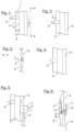
- Fig.1 shows a double-layer film web 1 with two longitudinal cuts 2, which are shown with broken lines.
- the film web runs in the transport direction z. It can be seen that the longitudinal cuts 2 are spaced apart from the side edge 3 by a distance A. The distance A to the nearest side edge 3 can also be different for each longitudinal cut, which does not limit the functionality of the invention.
- a pressing element 4 is also shown. In particular, two pressing elements spaced apart in the transport direction z can be provided.
- a Pressing element 4 can be designed as a roller so that it rolls on the film web 1 while it is in contact with it.
- the Figure 2 now shows that the pressing element was moved in direction x (orthogonal to the plane defined by the film), the pressing element only being in contact with a region of the film web 1, which lies between the side edge 3 and the next adjacent longitudinal section 2. This makes it possible to separate the first layer 5 of the film web 1 and the second layer 6 of the film web in the x direction.
- the Figure 3 now indicates that the pressing element can also be moved in the direction y, i.e. orthogonally to the directions x and z, while keeping the layers 5 and 6 spaced apart. The result is in the Figure 4 shown. In this view, the pressing element is below layer 5 but above layer 6.
- a holding device 7 can now be seen, on which an insertion tape 8 is held on the side facing the film web.
- the holding device can now be moved in the -y direction so that the insertion band lies above the first layer 5.
- a connection unit 9 and a separation unit 10 can be seen. These can be arranged together on a carrier 11, which can be positioned between the two layers 5 and 6.
- the layer 5 can now be pressed onto the insertion tape 8 and connected.
- the insertion tape can already be prepared with a double-sided adhesive tape 12.
- the separating unit 10 can now separate the layer 5 below the connection point, which can be done in particular at the same time as the layer 5 is pressed against the insertion tape 8.
Landscapes
- Engineering & Computer Science (AREA)
- Mechanical Engineering (AREA)
- Life Sciences & Earth Sciences (AREA)
- Forests & Forestry (AREA)
- Replacement Of Web Rolls (AREA)
Description
- Die Erfindung betrifft eine Vorrichtung und ein Verfahren zum Trennen einer doppellagigen Folienbahn in zwei einlagige Folienbahnen und zum Starten des Aufwickelns einer der einlagigen Folienbahnen.
- Blasfolienanlagen, mit denen eine doppellagige Folienbahn herstellbar ist, werden seit vielen Jahren eingesetzt. Häufig ist in einer solchen Blasfolienanlage ein Düsenkopf vorgesehen, welcher einen Düsenspalt aufweist, der insbesondere kreisrund ausgebildet ist. Aus diesem Düsenkopf wird eine Kunststoffschmelze ausgepresst beziehungsweise extrudiert, so dass ein Folienschlauch entsteht. Eine der in Transportrichtung des Folienschlauches nachfolgenden Einrichtungen ist eine Flachlegeeinrichtung und/oder Abquetscheinrichtung, mit welcher der Folienschlauch flachlegbar ist, so dass aus dem kreisrunden Folienschlauch die doppellagige Folienbahn entsteht, wobei die beiden Lagen entlang ihrer Längskanten miteinander verbunden sind.
- Oft ist es gewünscht, die doppellagige Folienbahn aufzutrennen und als jeweils eine einzelne Lage jeweils einer Wickelstelle innerhalb einer Wickelstation oder innerhalb von zwei Wicklern zuzuführen und dort aufzuwickeln. Bei Produktionsstart, also im Anfahrprozess, muss die Aufteilung der doppellagigen Folienbahn auf zwei Wickelstellen händisch erfolgen. Dabei wird zunächst der flachgelegte Folienschlauch einer einzigen, ersten Wickelstelle zugeführt und dort aufgewickelt. Sobald die gewünschte Folienqualität und Breite erreicht ist, wird der flachgelegte Schlauch durch Seitenschlitzmesser in zwei einlagige
- Folienbahnen, so genannte Flachbahnen, getrennt. Im Anschluss muss der Bediener die beiden noch aufeinander liegenden Flachbahnen manuell trennen, indem er versucht die eine Flachbahn von der anderen abzuheben und seine Hand zwischen die beiden Bahnen zu bringen. Sobald dem Bediener dieses gelungen ist, trennt er die Bahn mit einem Messer (Cuttermesser oder ähnlich) und vereinzelt somit die Bahnen. Den hierdurch erzeugten Flachbahnanfang verknotet er jetzt manuell mit der in die zweite Wickelstelle eingezogene Folie oder alternativ mit einem Anfahrband. Nachdem die Verknotung erfolgt ist, muss der Bediener die zweite Wickelstelle starten. Während der Zeit nach dem Trennen der Bahn und des Anknotens produziert die Blasfolienanlage mit einer reduzierten Bahngeschwindigkeit, um das manuelle Trennen und Anknoten sowie dadurch entstehende Lose (Materialbahnüberschuss) nicht zu groß werden zu lassen. Eine zu große Lose kann zu einer Verwirrung/Verknotung der Folienbahn führen, welche wiederum für den Bediener aufgrund von Einzugsgefahr gefährlich sein kann. Zudem besteht beim Anknoten die Gefahr, dass der Bediener Gliedmaßen (Finger/Hand) versehentlich einknotet und somit bei zu früher Freigabe des Anfahrens der Wickelstelle eingezogen werden kann.
- Erst nachdem die zweite Wickelstelle mit der Folienbahn versorgt ist, kann die Blasfolienanlage auf gewünschte Bahngeschwindigkeit gebracht werden, und somit können Produktionsbedingungen erzeugt werden.
- Im Falle eines Flachbahnverlustes an einer Wickelstelle muss die Produktionsgeschwindigkeit zunächst reduziert werden, damit ein erneutes manuelles Trennen und Anknoten erfolgen kann.
- Insgesamt ist der Vorgang nicht nur zeitraubend, sondern es bestehen für den Bediener die beschriebenen und durch den Umgang mit einem Messer hervorgerufenen Unfallgefahren.
- Die
DE 21 28 534 A1 beschreibt eine Vorrichtung, die zum Einführen von Seitenschlitzmessern vorgesehen ist. Hierbei werden die beiden Lagen der doppellagigen Folienbahn durch zwei mit klebrigen Mantelflächen voneinander getrennt, so dass zwischen diese beiden Lagen ein Seitenschlitzmesser eingeführt werden kann. Nachteilig ist dabei, dass die klebrigen Mantelflächen einem Verschleiß unterliegen und daher nicht immer zuverlässig ihren Zweck erfüllen. - Die
DE 102 43 958 A1 zeigt Schneidvorrichtungen, mit welchem die Seitenkanten der noch nicht vollständig aufeinander liegenden Lagen des Folienschlauches aufschneidet, bevor dieser die Abquetscheinrichtung erreicht hat. Nachteilig ist dabei, dass eine Vorabquetschung notwendig ist und die verschleißbehafteten Schneidmesser an einer schlecht erreichbaren Stelle innerhalb der Blasfolienanlage gewechselt werden müssen. - Die Aufgabe der vorliegenden Erfindung ist es daher, eine Vorrichtung und ein Verfahren vorzuschlagen, mit welchen die Unfallgefahren für den Bediener reduziert werden und mit welchen die weiteren genannten Nachteile vermeidbar sind.
- Die Aufgabe wird gelöst durch die Merkmale des Anspruchs 1.
- Demnach ist eine Vorrichtung zum Auftrennen einer doppellagigen Folienbahn vorgesehen, welche Folienbahn zunächst auf einer Wickelstelle aufwickelbar ist, wobei die beiden Lagen der Folienbahn zunächst über zwei Seitenränder miteinander verbunden sind, wobei die Vorrichtung die folgenden Merkmale umfasst:
- zwei Längsschneideinheiten, mit welchen in eine erste der beiden Lagen der doppellagigen Folienbahn Längsschnitte vorgesehen sind, welche von Seitenrändern beabstandet sind, so dass die eine Lage eine geringere Breite aufweist als die doppellagige Folienbahn,
- zumindest ein Drückelement, welches in orthogonaler Richtung der Ebene, welche durch die doppellagige Folienbahn aufgespannt ist, bewegbar ist, wobei die beiden Lagen der doppellagigen Folienbahn voneinander beabstandbar sind, wobei das Drückelement nur mit einem Bereich der Folienbahn in Kontakt steht, der zwischen der Seitenkante und nächsten benachbarten Längsschnitt liegt, und welches in der Ebene der doppellagigen Folienbahn, aber senkrecht zu ihrer Längsrichtung bewegbar ist, so dass das Drückelement zwischen die beiden Lagen der doppellagigen Folienbahn führbar ist.
- Diese Erfindung bietet den Vorteil, dass insbesondere durch die beiden Längsschnitte zunächst eine schmale erste Lage entsteht und die zweite Lage sozusagen um die Seitenkanten herum reicht. Mit dem Drückelement kann nun die zweite Lage zurückgedrückt und von der ersten Lage getrennt werden. Bevorzugt reicht die Trennung so weit, dass das Drückelement nun auch in der Ebene der Folienbahn, aber senkrecht zu ihrer Längsrichtung verschiebbar ist, so dass das Drückelement, welches vorteilhafterweise als Rolle oder Walze ausgestaltet ist, zwischen die beiden Lagen schiebbar ist. Dadurch können die beiden Lagen nicht wieder zusammenfallen. Damit kann der Bediener nun mit einem Messer einen Längsschnitt durchführen, ohne dass er zuvor händisch die Bahnen trennen muss, was die Unfallgefahr bereits reduziert.
- Vorteilhaft ist es jedoch, dass eine Trenneinrichtung vorgesehen ist, mit welcher die erste Lage der doppellagigen Folienbahn trennbar ist, so dass ein neuer Bahnanfang entsteht. In diesem Fall ist es nicht mehr notwendig, dass der Bediener mit einem Messer tätig wird, um die erste Lage zu durchtrennen. Somit wird die Unfallgefahr weiter reduziert. Dem Bediener bleibt in diesem Fall nur noch, den neuen Bahnanfang mit dem Einführband zu verbinden.
- In einer weiteren vorteilhaften Ausgestaltung der Erfindung ist eine Halteeinrichtung vorgesehen, mit welcher ein Einführband haltbar und an die erste Lage heranführbar ist. Somit kann auch der Bediener hiervon entlastest werden, denn es ist zu bedenken, dass eine laufende Bahn stets eine Unfall- und Verletzungsgefahr darstellt. Der Bediener muss lediglich dafür Sorge tragen, dass das Einführband in die Halteeinrichtung eingelegt wird. Dieses kann bereits vor dem Start der gesamten Blasfolienanlage erfolgen und/oder mit einem Abstand zu laufenden Bahn, was keine Gesundheitsgefahr für den Bediener darstellt. Als Einführband wird jegliches Mittel verstanden, welches in der Lage ist, den mit ihm verbundenen Bahnanfang in den Wickler einzuziehen, also insbesondere eine Folie (beispielsweise aus einem vorherigen Auftrag) oder das oben beschriebene Anfahrband.
- In einer weiteren, vorteilhaften Ausführungsform ist eine Verbindungseinrichtung vorgesehen, mit welcher der neue Bahnanfang und das Einführband miteinander verbindbar sind. Damit wird dem Bediener auch das Zusammenknoten des Einführbandes und des Bahnanfangs erspart, so dass dieser beim Anwickeln der ersten Lage auf eine weitere Wickelstelle nicht mehr manuell tätig werden muss. Die Verbindungseinrichtung kann dabei beispielsweise mit einem Stempel ausgestattet sein, mit welchem der Bahnanfang gegen das Einführband, was vorzugsweise mit einem doppelseitigen Klebeband versehen ist, drückbar ist.
- Anschließend ist es nur noch notwendig, den neuen Bahnanfang auf einen in der Wickelstelle befindlichen Wickel aufzuwickeln.
- Die erfindungsgemäße Vorrichtung ist vorzugsweise Bestandteil einer eingangs beschriebenen Blasfolienanlage. Bevorzugt umfasst diese die Längsschneideinheit. Diese kann im Bereich der Flachlegeeinrichtung angeordnet sein und insbesondere an dieser beweglich befestigt sein, so dass bereits bevor der Folienschlauch endgültig in eine doppellagigen Folienbahn überführt wurde, ein Längsschnitt einbringbar ist. In diesem Fall kann es vermieden werden, dass die zweite Lage der doppellagigen Folienbahn ebenfalls ungewollt mit Schnitten versehen wird. In der Flachlegeeinrichtung kann auch eine zweite Längsschneideeinheit vorgesehen sein.
- Es ist jedoch auch denkbar, einen ersten Längsschnitt dazu zu verwenden, weitere im Transportweg der doppellagigen Folienbahn angeordnete Längsschneideeinheiten in Eingriff mit der Folienbahn zu bringen. Dazu können weitere Drückelemente vorgesehen sein, mit welchen ebenfalls ein Abstand zwischen der ersten und der zweiten Lage der doppellagigen Folienbahn erzeugbar ist, welcher dazu nutzbar ist, Längsschneideinheiten, insbesondere in Form von Seitenkantenschlitzmessern einzubringen.
- Die oben beschriebene Aufgabe wird zusätzlich gelöst durch ein Verfahren zum Auftrennen einer doppellagigen Folienbahn, welche zunächst auf einer Wickelstelle aufgewickelt wird, wobei die beiden Lagen der Folienbahn zunächst über zwei Seitenränder miteinander verbunden sind, wobei das Verfahren die folgenden Merkmale umfasst:
- Einfügen zweier Längsschnitte in eine erste der beiden Lagen der doppellagigen Folienbahn mit zwei Längsschneideinheiten, wobei die Längsschnitte von Seitenrändern beabstandet sind, so dass die eine Lage eine geringere Breite aufweist als die doppellagige Folienbahn,
- Voneinander-Trennen der beiden Lagen der doppellagigen Folienbahn mit zumindest einem Drückelement, welches in orthogonaler Richtung der Ebene, welche durch die doppellagige Folienbahn aufgespannt ist, bewegt wird,
- Führen des Drückelements zwischen die beiden Lagen der doppellagigen Folienbahn, wobei das Drückelement in der Ebene der doppellagigen Folienbahn aber senkrecht zu ihrer Längsrichtung bewegt wird.
- Damit werden die gleichen Vorteile erzielt, die bereits im Zusammenhang mit einer erfindungsgemäßen Vorrichtung erzielt wurden.
- Weitere Vorteile, Merkmale und Einzelheiten der Erfindung gehen aus der nachfolgenden Beschreibung hervor, in der unter Bezugnahme auf die Figuren verschiedene Ausführungsbeispiele im Einzelnen erläutert sind. Dabei können die in den Ansprüchen und in der Beschreibung erwähnten Merkmale jeweils einzeln für sich oder beliebige Kombinationen erwähnter Merkmale erfindungswesentlich sein. Im Rahmen der gesamten Offenbarung gelten Merkmale und Einzelheiten, die im Zusammenhang mit dem erfindungsgemäßen Verfahren beschrieben sind, selbstverständlich auch im Zusammenhang mit der erfindungsgemäßen Vorrichtung und jeweils umgekehrt, so dass bezüglich der Offenbarung zu den einzelnen Aspekten der Erfindung stets wechselseitig Bezug genommen wird beziehungsweise werden kann. Die einzelnen Figuren zeigen:
- Fig. 1
- Eine doppellagige Folienbahn mit zwei Längsschnitten
- Fig. 2
- Die doppellagige Folienbahn mit Drückelement
- Fig. 3
- Die doppellagige Folienbahn vor einem Verschieben des Drückelements
- Fig. 4
- Die doppellagige Folienbahn mit dem sich zwischen den Lagen befindenden Drückelement.
- Fig. 5
- Die Situation gemäß
Figur 4 mit einem zusätzlich dargestellten Halteelement - Fig. 6
- Die doppellagige Folienbahn, nun zusätzlich mit einer Verbindungseinrichtung und einer Trenneinrichtung.
-
Fig. 1 zeigt eine doppellagige Folienbahn 1 mit zwei Längsschnitten 2, die mit unterbrochenen Linien dargestellt sind. Die Folienbahn läuft in Transportrichtung z. Zu erkennen ist, dass die Längsschnitte 2 mit einem Abstand A von der Seitenkante 3 beabstandet sind. Der Abstand A zur nächstliegenden Seitenkante 3 kann für jeden Längsschnitt auch unterschiedlich sein, was die Funktionsfähigkeit der Erfindung nicht einschränkt. Weiterhin ist ein Drückelement 4 gezeigt. Insbesondere können zwei in Transportrichtung z beabstandete Drückelemente vorgesehen sein. Ein Drückelement 4 kann als Rolle ausgebildet sein, so dass diese auf der Folienbahn 1 abrollt, während sie mit dieser in Kontakt steht. - Die
Figur 2 zeigt nun, dass das Drückelement in Richtung x (orthogonal zur Ebene, die durch die Folie definiert wird) bewegt wurde, wobei das Drückelement nur mit einem Bereich der Folienbahn 1 in Kontakt steht, der zwischen der Seitenkante 3 und nächsten benachbarten Längsschnitt 2 liegt. Damit ist es möglich, die erste Lage 5 der Folienbahn 1 und die zweite Lage 6 der Folienbahn in Richtung x zu trennen. - Die
Figur 3 deutet nun an, dass zusätzlich das Drückelement in Richtung y, also orthogonal zu den Richtungen x und z bewegbar ist, während die die Lagen 5 und 6 beabstandet hält. Das Ergebnis ist in derFigur 4 gezeigt. In dieser Ansicht liegt das Drückelement unterhalb der Lage 5, aber oberhalb der Lage 6. - In der
Figur 5 ist nun eine Halteeinrichtung 7 zu erkennen, an der auf der der Folienbahn zugewandten Seite ein Einführband 8 gehalten wird. Die Halteeinrichtung kann nun in Richtung -y verlagert werden, so dass das Einführband oberhalb der ersten Lage 5 liegt. Dies ist in derFigur 6 zu erkennen. Weiterhin sind in derFigur 6 eine Verbindungseinheit 9 und eine Trenneinheit 10 zu erkennen. Diese können gemeinsam auf einem Träger 11 angeordnet sein, welcher zwischen den beiden Lagen 5 und 6 positionierbar sein kann. Mit der Verbindungseinheit kann nun die Lage 5 an das Einführband 8 gedrückt und verbunden werden. Beispielsweise kann das Einführband bereits mit einem doppelseitigen Klebeband 12 präpariert sein. Die Trenneinheit 10 kann nun die Lage 5 unterhalb der Verbindungsstelle trennen, was insbesondere zeitgleich mit dem Andrücken der Lage 5 an das Einführband 8 erfolgen kann. Nun kann die zweite Wickelstelle gestartet werden, so dass das Einführband die Lage 5 in Richtung auf diese Wickelstelle zieht, so dass die erste Lage dort aufgewickelt werden kann, was allerdings nicht dargestellt ist.Bezugszeichenliste 1 Doppellagige Folienbahn 2 Längsschnitt 3 Seitenkante 4 Drückelement 5 Erste Lage 6 Zweite Lage 7 Halteeinrichtung 8 Einführband 9 Verbindungseinheit 10 Trenneinheit 11 Träger 12 Doppelseitiges Klebeband 13 14 15
Claims (5)
- Vorrichtung zum Auftrennen einer doppellagigen Folienbahn (1), welche zunächst auf einer Wickelstelle aufwickelbar ist, wobei die beiden Lagen (5, 6) der Folienbahn (1) zunächst über zwei Seitenränder (3) miteinander verbunden sind, wobei die Vorrichtung die folgenden Merkmale umfasst:• wenigstens zwei Längsschneideinheiten, mit welcher in eine erste der beiden Lagen (5, 6) der doppellagigen Folienbahn (1) zwei Längsschnitte (2) einbringbar sind, welche von Seitenrändern (3) beabstandet sind, so dass die eine Lage (5) eine geringere Breite aufweist als die doppellagige Folienbahn (1),• zumindest ein Drückelement (4), welches in orthogonaler Richtung (x) der Ebene, welche durch die doppellagige Folienbahn (1) aufgespannt ist, bewegbar ist, wobei die beiden Lagen (5, 6) der doppellagigen Folienbahn (1) voneinander beabstandbar sind, wobei das Drückelement (4) nur mit einem Bereich der Folienbahn (1) in Kontakt steht, der zwischen der Seitenkante (3) und nächsten benachbarten Längsschnitt (2) liegt, und welches in der Ebene (y) der doppellagigen Folienbahn (1), aber senkrecht zu ihrer Längsrichtung (z) bewegbar ist, so dass das Drückelement (4) zwischen die beiden Lagen (5, 6) der doppellagigen Folienbahn (1) führbar ist,.
- Vorrichtung nach Anspruch 1,
dadurch gekennzeichnet, dass
eine Trenneinrichtung (10) vorgesehen ist, mit welcher die erste Lage (5) der doppellagigen Folienbahn (1) trennbar ist, so dass ein neuer Bahnanfang entsteht. - Vorrichtung nach einem der vorstehenden Ansprüche,
dadurch gekennzeichnet, dass
eine Halteeinrichtung (7) vorgesehen ist, mit welcher ein Einführband (8) haltbar und an die erste Lage (5) heranführbar ist. - Vorrichtung nach einem der vorstehenden Ansprüche,
dadurch gekennzeichnet, dass
eine Verbindungseinrichtung (9) vorgesehen ist, mit welcher der neue Bahnanfang und das Einführband (8) miteinander verbindbar sind, - Verfahren zum Auftrennen einer doppellagigen Folienbahn (1), welche zunächst auf einer Wickelstelle aufgewickelt wird, wobei die beiden Lagen (5, 6) der Folienbahn (1) zunächst über zwei Seitenränder (3) miteinander verbunden sind, wobei das Verfahren die folgenden Merkmale umfasst:• Einfügen zweier Längsschnitte in eine erste der beiden Lagen (5, 6) der doppellagigen Folienbahn (1) mit zwei Längsschneideinheiten, wobei die Längsschnitte von Seitenrändern (3) beabstandet sind, so dass die eine Lage (5) eine geringere Breite aufweist als die doppellagige Folienbahn (1),• Trennen der beiden Lagen (5, 6) der doppellagigen Folienbahn (1) voneinander mit zumindest einem Drückelement (4), welches in orthogonaler Richtung (x) der Ebene (z, y), welche durch die doppellagige Folienbahn (1) aufgespannt ist, bewegt wird,Führen des Drückelements (4) zwischen die beiden Lagen (5, 6) der doppellagigen Folienbahn (6), wobei das Drückelement (4) in der Ebene der doppellagigen Folienbahn (1), aber senkrecht zu ihrer Längsrichtung (z) bewegt wird.
Applications Claiming Priority (2)
| Application Number | Priority Date | Filing Date | Title |
|---|---|---|---|
| DE102019215837.4A DE102019215837A1 (de) | 2019-10-15 | 2019-10-15 | Verbindungs-, Trenneinheit für Folienbahnen |
| PCT/EP2020/078823 WO2021074177A1 (de) | 2019-10-15 | 2020-10-14 | Verbindungs-, trenneinheit für folienbahnen |
Publications (2)
| Publication Number | Publication Date |
|---|---|
| EP4045271A1 EP4045271A1 (de) | 2022-08-24 |
| EP4045271B1 true EP4045271B1 (de) | 2024-04-03 |
Family
ID=72915816
Family Applications (1)
| Application Number | Title | Priority Date | Filing Date |
|---|---|---|---|
| EP20792959.7A Active EP4045271B1 (de) | 2019-10-15 | 2020-10-14 | Verbindungs-, trenneinheit für folienbahnen |
Country Status (4)
| Country | Link |
|---|---|
| US (1) | US12521902B2 (de) |
| EP (1) | EP4045271B1 (de) |
| DE (1) | DE102019215837A1 (de) |
| WO (1) | WO2021074177A1 (de) |
Families Citing this family (1)
| Publication number | Priority date | Publication date | Assignee | Title |
|---|---|---|---|---|
| CN115816911B (zh) * | 2022-12-15 | 2024-05-10 | 温州喜发实业有限公司 | 一种彩印编织袋的复合接续工艺 |
Family Cites Families (6)
| Publication number | Priority date | Publication date | Assignee | Title |
|---|---|---|---|---|
| US2757495A (en) | 1950-09-06 | 1956-08-07 | American Viscose Corp | Process for the production of stuffed products |
| US3068730A (en) * | 1960-05-04 | 1962-12-18 | Nat Distillers Chem Corp | Apparatus for slitting tubular sheet materials |
| DE2128534C3 (de) * | 1971-06-08 | 1974-01-24 | Windmoeller & Hoelscher, 4540 Lengerich | Vorrichtung zum Auftrennen flachgelegter nahtloser Kunststoffolienschläuche |
| US5533889A (en) * | 1994-08-29 | 1996-07-09 | International Business Machines Corporation | Apparatus for in-situ green sheet slitting |
| US6394330B1 (en) * | 1998-08-13 | 2002-05-28 | 3M Innovative Properties Company | Method for slitting and processing a web into plural use supply forms |
| DE10243958A1 (de) * | 2002-09-20 | 2004-04-08 | Windmöller & Hölscher Kg | Verfahren zur Bereitstellung von Folienbahnen |
-
2019
- 2019-10-15 DE DE102019215837.4A patent/DE102019215837A1/de active Pending
-
2020
- 2020-10-14 WO PCT/EP2020/078823 patent/WO2021074177A1/de not_active Ceased
- 2020-10-14 US US17/768,330 patent/US12521902B2/en active Active
- 2020-10-14 EP EP20792959.7A patent/EP4045271B1/de active Active
Also Published As
| Publication number | Publication date |
|---|---|
| EP4045271A1 (de) | 2022-08-24 |
| US20240165839A1 (en) | 2024-05-23 |
| DE102019215837A1 (de) | 2021-04-15 |
| US12521902B2 (en) | 2026-01-13 |
| WO2021074177A1 (de) | 2021-04-22 |
Similar Documents
| Publication | Publication Date | Title |
|---|---|---|
| DE69405151T2 (de) | Gerät zum Schneiden einer Materialbahn auf bestimmte Länge und zum Ausgeben derselben | |
| EP2257488B1 (de) | Vorrichtung und verfahren zum sichern eines bahnendes auf einem tambour | |
| DE69514112T2 (de) | Gummibandkette, verfahren und vorrichtung zu deren herstellung, sowie verfahren und vorrichtung für die zufuhr der gummibänder zu einer behandlungsvorrichtung | |
| DE2229497A1 (de) | Verfahren und Vorrichtung zum Fordern von flachenhaftem Gut | |
| DD149199A1 (de) | Vorrichtung zur bewerkstelligung eines fliegenden rollenwechsels | |
| EP3150366B1 (de) | Verfahren zum herstellen eines abdichtbandes, abdichtband und vorrichtung zur durchführung des verfahrens | |
| EP2803609B1 (de) | Maschine zum Aufwickeln von bahnförmigen Materialien | |
| EP4045271B1 (de) | Verbindungs-, trenneinheit für folienbahnen | |
| EP2874790B1 (de) | Schneidvorrichtung und verfahren zum quertrennen einer laufenden faserstoffbahn | |
| EP0033065B1 (de) | Verfahren zum Spalten eines Bandes und Spaltanlage für Bänder | |
| DE2547699C3 (de) | Verfahren und Vorrichtung zum Einleiten eines Aufwickelvorganges | |
| DE102019116263A1 (de) | Einrichtung mit einer Mehrfach-Strangbildungsvorrichtung und Verfahren der Tabak verarbeitenden Industrie | |
| EP0982228B1 (de) | Verfahren und Vorrichtung zum Verpacken von Materialbahnrollen | |
| EP0963909A1 (de) | Verfahren und Vorrichtung zum Herstellen einer am Umfang verpackten Materialbahnrolle und Materialbahnrolle | |
| EP1179630B1 (de) | Verfahren und Vorrichtung zum Herstellen von Papierrollen | |
| EP3181311B1 (de) | Vorrichtung zum herauslösen von teilbereichen aus einer materialbahn | |
| EP3880592B1 (de) | Verfahren und vorrichtung zum sukzessiven aufwickeln einer folienbahn sowie folienrolle | |
| DE102004016841A1 (de) | Folie mit Verstärkungsstreifen sowie Vorrichtung und Verfahren zur Herstellung der Folie | |
| DE10243959B4 (de) | Vorrichtung zur Herstellung von Folienbahnen aus einem Folienschlauch | |
| DE4140365C2 (de) | Vorrichtung zum Beschneiden einer Materialbahn | |
| EP1151947B1 (de) | Verfahren zum Aufführen mehrerer aus einer Materialbahn geschnittener Teilbahnen auf Teilbahnrollen und Wickelvorrichtung | |
| DE10348179B3 (de) | Vorrichtung und Verfahren zum Herstellen mindestens zweier Banderolenbahnen aus einem bahnförmigen Material | |
| DE60037716T2 (de) | Verfahren und Vorrichtung zum Bandagieren | |
| DE3325237C2 (de) | ||
| EP1542859B1 (de) | Verfahren zur bereitstellung von folienbahnen |
Legal Events
| Date | Code | Title | Description |
|---|---|---|---|
| STAA | Information on the status of an ep patent application or granted ep patent |
Free format text: STATUS: UNKNOWN |
|
| STAA | Information on the status of an ep patent application or granted ep patent |
Free format text: STATUS: THE INTERNATIONAL PUBLICATION HAS BEEN MADE |
|
| PUAI | Public reference made under article 153(3) epc to a published international application that has entered the european phase |
Free format text: ORIGINAL CODE: 0009012 |
|
| STAA | Information on the status of an ep patent application or granted ep patent |
Free format text: STATUS: REQUEST FOR EXAMINATION WAS MADE |
|
| 17P | Request for examination filed |
Effective date: 20220516 |
|
| AK | Designated contracting states |
Kind code of ref document: A1 Designated state(s): AL AT BE BG CH CY CZ DE DK EE ES FI FR GB GR HR HU IE IS IT LI LT LU LV MC MK MT NL NO PL PT RO RS SE SI SK SM TR |
|
| DAV | Request for validation of the european patent (deleted) | ||
| DAX | Request for extension of the european patent (deleted) | ||
| REG | Reference to a national code |
Ref country code: DE Ref legal event code: R079 Free format text: PREVIOUS MAIN CLASS: B29C0048100000 Ipc: B26D0003000000 Ref document number: 502020007584 Country of ref document: DE |
|
| GRAP | Despatch of communication of intention to grant a patent |
Free format text: ORIGINAL CODE: EPIDOSNIGR1 |
|
| STAA | Information on the status of an ep patent application or granted ep patent |
Free format text: STATUS: GRANT OF PATENT IS INTENDED |
|
| RIC1 | Information provided on ipc code assigned before grant |
Ipc: B29C 48/00 20190101ALN20231012BHEP Ipc: B26D 3/00 20060101AFI20231012BHEP |
|
| RIC1 | Information provided on ipc code assigned before grant |
Ipc: B29C 48/00 20190101ALN20231016BHEP Ipc: B26D 3/00 20060101AFI20231016BHEP |
|
| INTG | Intention to grant announced |
Effective date: 20231103 |
|
| GRAS | Grant fee paid |
Free format text: ORIGINAL CODE: EPIDOSNIGR3 |
|
| GRAA | (expected) grant |
Free format text: ORIGINAL CODE: 0009210 |
|
| STAA | Information on the status of an ep patent application or granted ep patent |
Free format text: STATUS: THE PATENT HAS BEEN GRANTED |
|
| AK | Designated contracting states |
Kind code of ref document: B1 Designated state(s): AL AT BE BG CH CY CZ DE DK EE ES FI FR GB GR HR HU IE IS IT LI LT LU LV MC MK MT NL NO PL PT RO RS SE SI SK SM TR |
|
| REG | Reference to a national code |
Ref country code: CH Ref legal event code: EP |
|
| REG | Reference to a national code |
Ref country code: DE Ref legal event code: R096 Ref document number: 502020007584 Country of ref document: DE |
|
| REG | Reference to a national code |
Ref country code: IE Ref legal event code: FG4D Free format text: LANGUAGE OF EP DOCUMENT: GERMAN |
|
| REG | Reference to a national code |
Ref country code: LT Ref legal event code: MG9D |
|
| REG | Reference to a national code |
Ref country code: NL Ref legal event code: MP Effective date: 20240403 |
|
| PG25 | Lapsed in a contracting state [announced via postgrant information from national office to epo] |
Ref country code: NL Free format text: LAPSE BECAUSE OF FAILURE TO SUBMIT A TRANSLATION OF THE DESCRIPTION OR TO PAY THE FEE WITHIN THE PRESCRIBED TIME-LIMIT Effective date: 20240403 |
|
| PG25 | Lapsed in a contracting state [announced via postgrant information from national office to epo] |
Ref country code: NL Free format text: LAPSE BECAUSE OF FAILURE TO SUBMIT A TRANSLATION OF THE DESCRIPTION OR TO PAY THE FEE WITHIN THE PRESCRIBED TIME-LIMIT Effective date: 20240403 |
|
| PG25 | Lapsed in a contracting state [announced via postgrant information from national office to epo] |
Ref country code: IS Free format text: LAPSE BECAUSE OF FAILURE TO SUBMIT A TRANSLATION OF THE DESCRIPTION OR TO PAY THE FEE WITHIN THE PRESCRIBED TIME-LIMIT Effective date: 20240803 |
|
| PG25 | Lapsed in a contracting state [announced via postgrant information from national office to epo] |
Ref country code: BG Free format text: LAPSE BECAUSE OF FAILURE TO SUBMIT A TRANSLATION OF THE DESCRIPTION OR TO PAY THE FEE WITHIN THE PRESCRIBED TIME-LIMIT Effective date: 20240403 |
|
| PG25 | Lapsed in a contracting state [announced via postgrant information from national office to epo] |
Ref country code: HR Free format text: LAPSE BECAUSE OF FAILURE TO SUBMIT A TRANSLATION OF THE DESCRIPTION OR TO PAY THE FEE WITHIN THE PRESCRIBED TIME-LIMIT Effective date: 20240403 Ref country code: FI Free format text: LAPSE BECAUSE OF FAILURE TO SUBMIT A TRANSLATION OF THE DESCRIPTION OR TO PAY THE FEE WITHIN THE PRESCRIBED TIME-LIMIT Effective date: 20240403 |
|
| PG25 | Lapsed in a contracting state [announced via postgrant information from national office to epo] |
Ref country code: GR Free format text: LAPSE BECAUSE OF FAILURE TO SUBMIT A TRANSLATION OF THE DESCRIPTION OR TO PAY THE FEE WITHIN THE PRESCRIBED TIME-LIMIT Effective date: 20240704 |
|
| PG25 | Lapsed in a contracting state [announced via postgrant information from national office to epo] |
Ref country code: PT Free format text: LAPSE BECAUSE OF FAILURE TO SUBMIT A TRANSLATION OF THE DESCRIPTION OR TO PAY THE FEE WITHIN THE PRESCRIBED TIME-LIMIT Effective date: 20240805 |
|
| PG25 | Lapsed in a contracting state [announced via postgrant information from national office to epo] |
Ref country code: ES Free format text: LAPSE BECAUSE OF FAILURE TO SUBMIT A TRANSLATION OF THE DESCRIPTION OR TO PAY THE FEE WITHIN THE PRESCRIBED TIME-LIMIT Effective date: 20240403 |
|
| PG25 | Lapsed in a contracting state [announced via postgrant information from national office to epo] |
Ref country code: CZ Free format text: LAPSE BECAUSE OF FAILURE TO SUBMIT A TRANSLATION OF THE DESCRIPTION OR TO PAY THE FEE WITHIN THE PRESCRIBED TIME-LIMIT Effective date: 20240403 |
|
| PG25 | Lapsed in a contracting state [announced via postgrant information from national office to epo] |
Ref country code: PL Free format text: LAPSE BECAUSE OF FAILURE TO SUBMIT A TRANSLATION OF THE DESCRIPTION OR TO PAY THE FEE WITHIN THE PRESCRIBED TIME-LIMIT Effective date: 20240403 |
|
| PG25 | Lapsed in a contracting state [announced via postgrant information from national office to epo] |
Ref country code: LV Free format text: LAPSE BECAUSE OF FAILURE TO SUBMIT A TRANSLATION OF THE DESCRIPTION OR TO PAY THE FEE WITHIN THE PRESCRIBED TIME-LIMIT Effective date: 20240403 |
|
| PG25 | Lapsed in a contracting state [announced via postgrant information from national office to epo] |
Ref country code: PT Free format text: LAPSE BECAUSE OF FAILURE TO SUBMIT A TRANSLATION OF THE DESCRIPTION OR TO PAY THE FEE WITHIN THE PRESCRIBED TIME-LIMIT Effective date: 20240805 Ref country code: PL Free format text: LAPSE BECAUSE OF FAILURE TO SUBMIT A TRANSLATION OF THE DESCRIPTION OR TO PAY THE FEE WITHIN THE PRESCRIBED TIME-LIMIT Effective date: 20240403 Ref country code: NO Free format text: LAPSE BECAUSE OF FAILURE TO SUBMIT A TRANSLATION OF THE DESCRIPTION OR TO PAY THE FEE WITHIN THE PRESCRIBED TIME-LIMIT Effective date: 20240703 Ref country code: LV Free format text: LAPSE BECAUSE OF FAILURE TO SUBMIT A TRANSLATION OF THE DESCRIPTION OR TO PAY THE FEE WITHIN THE PRESCRIBED TIME-LIMIT Effective date: 20240403 Ref country code: IS Free format text: LAPSE BECAUSE OF FAILURE TO SUBMIT A TRANSLATION OF THE DESCRIPTION OR TO PAY THE FEE WITHIN THE PRESCRIBED TIME-LIMIT Effective date: 20240803 Ref country code: HR Free format text: LAPSE BECAUSE OF FAILURE TO SUBMIT A TRANSLATION OF THE DESCRIPTION OR TO PAY THE FEE WITHIN THE PRESCRIBED TIME-LIMIT Effective date: 20240403 Ref country code: GR Free format text: LAPSE BECAUSE OF FAILURE TO SUBMIT A TRANSLATION OF THE DESCRIPTION OR TO PAY THE FEE WITHIN THE PRESCRIBED TIME-LIMIT Effective date: 20240704 Ref country code: FI Free format text: LAPSE BECAUSE OF FAILURE TO SUBMIT A TRANSLATION OF THE DESCRIPTION OR TO PAY THE FEE WITHIN THE PRESCRIBED TIME-LIMIT Effective date: 20240403 Ref country code: ES Free format text: LAPSE BECAUSE OF FAILURE TO SUBMIT A TRANSLATION OF THE DESCRIPTION OR TO PAY THE FEE WITHIN THE PRESCRIBED TIME-LIMIT Effective date: 20240403 Ref country code: CZ Free format text: LAPSE BECAUSE OF FAILURE TO SUBMIT A TRANSLATION OF THE DESCRIPTION OR TO PAY THE FEE WITHIN THE PRESCRIBED TIME-LIMIT Effective date: 20240403 Ref country code: BG Free format text: LAPSE BECAUSE OF FAILURE TO SUBMIT A TRANSLATION OF THE DESCRIPTION OR TO PAY THE FEE WITHIN THE PRESCRIBED TIME-LIMIT Effective date: 20240403 Ref country code: RS Free format text: LAPSE BECAUSE OF FAILURE TO SUBMIT A TRANSLATION OF THE DESCRIPTION OR TO PAY THE FEE WITHIN THE PRESCRIBED TIME-LIMIT Effective date: 20240703 |
|
| REG | Reference to a national code |
Ref country code: DE Ref legal event code: R097 Ref document number: 502020007584 Country of ref document: DE |
|
| PG25 | Lapsed in a contracting state [announced via postgrant information from national office to epo] |
Ref country code: DK Free format text: LAPSE BECAUSE OF FAILURE TO SUBMIT A TRANSLATION OF THE DESCRIPTION OR TO PAY THE FEE WITHIN THE PRESCRIBED TIME-LIMIT Effective date: 20240403 |
|
| PG25 | Lapsed in a contracting state [announced via postgrant information from national office to epo] |
Ref country code: EE Free format text: LAPSE BECAUSE OF FAILURE TO SUBMIT A TRANSLATION OF THE DESCRIPTION OR TO PAY THE FEE WITHIN THE PRESCRIBED TIME-LIMIT Effective date: 20240403 |
|
| PG25 | Lapsed in a contracting state [announced via postgrant information from national office to epo] |
Ref country code: RO Free format text: LAPSE BECAUSE OF FAILURE TO SUBMIT A TRANSLATION OF THE DESCRIPTION OR TO PAY THE FEE WITHIN THE PRESCRIBED TIME-LIMIT Effective date: 20240403 Ref country code: SK Free format text: LAPSE BECAUSE OF FAILURE TO SUBMIT A TRANSLATION OF THE DESCRIPTION OR TO PAY THE FEE WITHIN THE PRESCRIBED TIME-LIMIT Effective date: 20240403 |
|
| PG25 | Lapsed in a contracting state [announced via postgrant information from national office to epo] |
Ref country code: SM Free format text: LAPSE BECAUSE OF FAILURE TO SUBMIT A TRANSLATION OF THE DESCRIPTION OR TO PAY THE FEE WITHIN THE PRESCRIBED TIME-LIMIT Effective date: 20240403 |
|
| PG25 | Lapsed in a contracting state [announced via postgrant information from national office to epo] |
Ref country code: SM Free format text: LAPSE BECAUSE OF FAILURE TO SUBMIT A TRANSLATION OF THE DESCRIPTION OR TO PAY THE FEE WITHIN THE PRESCRIBED TIME-LIMIT Effective date: 20240403 Ref country code: SK Free format text: LAPSE BECAUSE OF FAILURE TO SUBMIT A TRANSLATION OF THE DESCRIPTION OR TO PAY THE FEE WITHIN THE PRESCRIBED TIME-LIMIT Effective date: 20240403 Ref country code: RO Free format text: LAPSE BECAUSE OF FAILURE TO SUBMIT A TRANSLATION OF THE DESCRIPTION OR TO PAY THE FEE WITHIN THE PRESCRIBED TIME-LIMIT Effective date: 20240403 Ref country code: EE Free format text: LAPSE BECAUSE OF FAILURE TO SUBMIT A TRANSLATION OF THE DESCRIPTION OR TO PAY THE FEE WITHIN THE PRESCRIBED TIME-LIMIT Effective date: 20240403 Ref country code: DK Free format text: LAPSE BECAUSE OF FAILURE TO SUBMIT A TRANSLATION OF THE DESCRIPTION OR TO PAY THE FEE WITHIN THE PRESCRIBED TIME-LIMIT Effective date: 20240403 |
|
| PLBE | No opposition filed within time limit |
Free format text: ORIGINAL CODE: 0009261 |
|
| STAA | Information on the status of an ep patent application or granted ep patent |
Free format text: STATUS: NO OPPOSITION FILED WITHIN TIME LIMIT |
|
| 26N | No opposition filed |
Effective date: 20250106 |
|
| PG25 | Lapsed in a contracting state [announced via postgrant information from national office to epo] |
Ref country code: SI Free format text: LAPSE BECAUSE OF FAILURE TO SUBMIT A TRANSLATION OF THE DESCRIPTION OR TO PAY THE FEE WITHIN THE PRESCRIBED TIME-LIMIT Effective date: 20240403 |
|
| GBPC | Gb: european patent ceased through non-payment of renewal fee |
Effective date: 20241014 |
|
| PG25 | Lapsed in a contracting state [announced via postgrant information from national office to epo] |
Ref country code: MC Free format text: LAPSE BECAUSE OF FAILURE TO SUBMIT A TRANSLATION OF THE DESCRIPTION OR TO PAY THE FEE WITHIN THE PRESCRIBED TIME-LIMIT Effective date: 20240403 |
|
| PG25 | Lapsed in a contracting state [announced via postgrant information from national office to epo] |
Ref country code: GB Free format text: LAPSE BECAUSE OF NON-PAYMENT OF DUE FEES Effective date: 20241014 |
|
| PG25 | Lapsed in a contracting state [announced via postgrant information from national office to epo] |
Ref country code: LU Free format text: LAPSE BECAUSE OF NON-PAYMENT OF DUE FEES Effective date: 20241014 Ref country code: BE Free format text: LAPSE BECAUSE OF NON-PAYMENT OF DUE FEES Effective date: 20241031 |
|
| PG25 | Lapsed in a contracting state [announced via postgrant information from national office to epo] |
Ref country code: FR Free format text: LAPSE BECAUSE OF NON-PAYMENT OF DUE FEES Effective date: 20241031 |
|
| REG | Reference to a national code |
Ref country code: BE Ref legal event code: MM Effective date: 20241031 |
|
| PG25 | Lapsed in a contracting state [announced via postgrant information from national office to epo] |
Ref country code: SE Free format text: LAPSE BECAUSE OF FAILURE TO SUBMIT A TRANSLATION OF THE DESCRIPTION OR TO PAY THE FEE WITHIN THE PRESCRIBED TIME-LIMIT Effective date: 20240403 |
|
| PGFP | Annual fee paid to national office [announced via postgrant information from national office to epo] |
Ref country code: TR Payment date: 20250917 Year of fee payment: 6 |
|
| PG25 | Lapsed in a contracting state [announced via postgrant information from national office to epo] |
Ref country code: IE Free format text: LAPSE BECAUSE OF NON-PAYMENT OF DUE FEES Effective date: 20241014 |
|
| REG | Reference to a national code |
Ref country code: CH Ref legal event code: U11 Free format text: ST27 STATUS EVENT CODE: U-0-0-U10-U11 (AS PROVIDED BY THE NATIONAL OFFICE) Effective date: 20251101 |
|
| PGFP | Annual fee paid to national office [announced via postgrant information from national office to epo] |
Ref country code: DE Payment date: 20251031 Year of fee payment: 6 |
|
| PGFP | Annual fee paid to national office [announced via postgrant information from national office to epo] |
Ref country code: AT Payment date: 20260113 Year of fee payment: 5 |
|
| PG25 | Lapsed in a contracting state [announced via postgrant information from national office to epo] |
Ref country code: IT Free format text: LAPSE BECAUSE OF NON-PAYMENT OF DUE FEES Effective date: 20241014 |
|
| PGFP | Annual fee paid to national office [announced via postgrant information from national office to epo] |
Ref country code: CH Payment date: 20251101 Year of fee payment: 6 |
|
| PG25 | Lapsed in a contracting state [announced via postgrant information from national office to epo] |
Ref country code: CY Free format text: LAPSE BECAUSE OF FAILURE TO SUBMIT A TRANSLATION OF THE DESCRIPTION OR TO PAY THE FEE WITHIN THE PRESCRIBED TIME-LIMIT; INVALID AB INITIO Effective date: 20201014 |
|
| PG25 | Lapsed in a contracting state [announced via postgrant information from national office to epo] |
Ref country code: HU Free format text: LAPSE BECAUSE OF FAILURE TO SUBMIT A TRANSLATION OF THE DESCRIPTION OR TO PAY THE FEE WITHIN THE PRESCRIBED TIME-LIMIT; INVALID AB INITIO Effective date: 20201014 |
|
| PG25 | Lapsed in a contracting state [announced via postgrant information from national office to epo] |
Ref country code: IT Free format text: LAPSE BECAUSE OF NON-PAYMENT OF DUE FEES Effective date: 20241014 |
|
| PGFP | Annual fee paid to national office [announced via postgrant information from national office to epo] |
Ref country code: IT Payment date: 20250922 Year of fee payment: 6 |
|
| PGRI | Patent reinstated in contracting state [announced from national office to epo] |
Ref country code: IT Effective date: 20250228 |