EP4043774B1 - Anschlussvorrichtung und damit versehenes serviceventil - Google Patents
Anschlussvorrichtung und damit versehenes serviceventil Download PDFInfo
- Publication number
- EP4043774B1 EP4043774B1 EP20872429.4A EP20872429A EP4043774B1 EP 4043774 B1 EP4043774 B1 EP 4043774B1 EP 20872429 A EP20872429 A EP 20872429A EP 4043774 B1 EP4043774 B1 EP 4043774B1
- Authority
- EP
- European Patent Office
- Prior art keywords
- pipe
- lock washer
- fitting
- fitting device
- washer spring
- Prior art date
- Legal status (The legal status is an assumption and is not a legal conclusion. Google has not performed a legal analysis and makes no representation as to the accuracy of the status listed.)
- Active
Links
Images


Classifications
-
- F—MECHANICAL ENGINEERING; LIGHTING; HEATING; WEAPONS; BLASTING
- F16—ENGINEERING ELEMENTS AND UNITS; GENERAL MEASURES FOR PRODUCING AND MAINTAINING EFFECTIVE FUNCTIONING OF MACHINES OR INSTALLATIONS; THERMAL INSULATION IN GENERAL
- F16L—PIPES; JOINTS OR FITTINGS FOR PIPES; SUPPORTS FOR PIPES, CABLES OR PROTECTIVE TUBING; MEANS FOR THERMAL INSULATION IN GENERAL
- F16L37/00—Couplings of the quick-acting type
- F16L37/08—Couplings of the quick-acting type in which the connection between abutting or axially overlapping ends is maintained by locking members
- F16L37/084—Couplings of the quick-acting type in which the connection between abutting or axially overlapping ends is maintained by locking members combined with automatic locking
- F16L37/091—Couplings of the quick-acting type in which the connection between abutting or axially overlapping ends is maintained by locking members combined with automatic locking by means of a ring provided with teeth or fingers
- F16L37/0915—Couplings of the quick-acting type in which the connection between abutting or axially overlapping ends is maintained by locking members combined with automatic locking by means of a ring provided with teeth or fingers with a separate member for releasing the coupling
-
- F—MECHANICAL ENGINEERING; LIGHTING; HEATING; WEAPONS; BLASTING
- F16—ENGINEERING ELEMENTS AND UNITS; GENERAL MEASURES FOR PRODUCING AND MAINTAINING EFFECTIVE FUNCTIONING OF MACHINES OR INSTALLATIONS; THERMAL INSULATION IN GENERAL
- F16K—VALVES; TAPS; COCKS; ACTUATING-FLOATS; DEVICES FOR VENTING OR AERATING
- F16K27/00—Construction of housing; Use of materials therefor
-
- F—MECHANICAL ENGINEERING; LIGHTING; HEATING; WEAPONS; BLASTING
- F16—ENGINEERING ELEMENTS AND UNITS; GENERAL MEASURES FOR PRODUCING AND MAINTAINING EFFECTIVE FUNCTIONING OF MACHINES OR INSTALLATIONS; THERMAL INSULATION IN GENERAL
- F16K—VALVES; TAPS; COCKS; ACTUATING-FLOATS; DEVICES FOR VENTING OR AERATING
- F16K31/00—Actuating devices; Operating means; Releasing devices
- F16K31/44—Mechanical actuating means
- F16K31/60—Handles
-
- F—MECHANICAL ENGINEERING; LIGHTING; HEATING; WEAPONS; BLASTING
- F16—ENGINEERING ELEMENTS AND UNITS; GENERAL MEASURES FOR PRODUCING AND MAINTAINING EFFECTIVE FUNCTIONING OF MACHINES OR INSTALLATIONS; THERMAL INSULATION IN GENERAL
- F16L—PIPES; JOINTS OR FITTINGS FOR PIPES; SUPPORTS FOR PIPES, CABLES OR PROTECTIVE TUBING; MEANS FOR THERMAL INSULATION IN GENERAL
- F16L33/00—Arrangements for connecting hoses to rigid members; Rigid hose-connectors, i.e. single members engaging both hoses
-
- F—MECHANICAL ENGINEERING; LIGHTING; HEATING; WEAPONS; BLASTING
- F16—ENGINEERING ELEMENTS AND UNITS; GENERAL MEASURES FOR PRODUCING AND MAINTAINING EFFECTIVE FUNCTIONING OF MACHINES OR INSTALLATIONS; THERMAL INSULATION IN GENERAL
- F16L—PIPES; JOINTS OR FITTINGS FOR PIPES; SUPPORTS FOR PIPES, CABLES OR PROTECTIVE TUBING; MEANS FOR THERMAL INSULATION IN GENERAL
- F16L37/00—Couplings of the quick-acting type
- F16L37/08—Couplings of the quick-acting type in which the connection between abutting or axially overlapping ends is maintained by locking members
- F16L37/084—Couplings of the quick-acting type in which the connection between abutting or axially overlapping ends is maintained by locking members combined with automatic locking
- F16L37/098—Couplings of the quick-acting type in which the connection between abutting or axially overlapping ends is maintained by locking members combined with automatic locking by means of flexible hooks
-
- F—MECHANICAL ENGINEERING; LIGHTING; HEATING; WEAPONS; BLASTING
- F16—ENGINEERING ELEMENTS AND UNITS; GENERAL MEASURES FOR PRODUCING AND MAINTAINING EFFECTIVE FUNCTIONING OF MACHINES OR INSTALLATIONS; THERMAL INSULATION IN GENERAL
- F16L—PIPES; JOINTS OR FITTINGS FOR PIPES; SUPPORTS FOR PIPES, CABLES OR PROTECTIVE TUBING; MEANS FOR THERMAL INSULATION IN GENERAL
- F16L37/00—Couplings of the quick-acting type
- F16L37/22—Couplings of the quick-acting type in which the connection is maintained by means of balls, rollers or helical springs under radial pressure between the parts
-
- F—MECHANICAL ENGINEERING; LIGHTING; HEATING; WEAPONS; BLASTING
- F16—ENGINEERING ELEMENTS AND UNITS; GENERAL MEASURES FOR PRODUCING AND MAINTAINING EFFECTIVE FUNCTIONING OF MACHINES OR INSTALLATIONS; THERMAL INSULATION IN GENERAL
- F16L—PIPES; JOINTS OR FITTINGS FOR PIPES; SUPPORTS FOR PIPES, CABLES OR PROTECTIVE TUBING; MEANS FOR THERMAL INSULATION IN GENERAL
- F16L37/00—Couplings of the quick-acting type
- F16L37/28—Couplings of the quick-acting type with fluid cut-off means
-
- F—MECHANICAL ENGINEERING; LIGHTING; HEATING; WEAPONS; BLASTING
- F16—ENGINEERING ELEMENTS AND UNITS; GENERAL MEASURES FOR PRODUCING AND MAINTAINING EFFECTIVE FUNCTIONING OF MACHINES OR INSTALLATIONS; THERMAL INSULATION IN GENERAL
- F16L—PIPES; JOINTS OR FITTINGS FOR PIPES; SUPPORTS FOR PIPES, CABLES OR PROTECTIVE TUBING; MEANS FOR THERMAL INSULATION IN GENERAL
- F16L41/00—Branching pipes; Joining pipes to walls
- F16L41/02—Branch units, e.g. made in one piece, welded, riveted
-
- F—MECHANICAL ENGINEERING; LIGHTING; HEATING; WEAPONS; BLASTING
- F16—ENGINEERING ELEMENTS AND UNITS; GENERAL MEASURES FOR PRODUCING AND MAINTAINING EFFECTIVE FUNCTIONING OF MACHINES OR INSTALLATIONS; THERMAL INSULATION IN GENERAL
- F16L—PIPES; JOINTS OR FITTINGS FOR PIPES; SUPPORTS FOR PIPES, CABLES OR PROTECTIVE TUBING; MEANS FOR THERMAL INSULATION IN GENERAL
- F16L41/00—Branching pipes; Joining pipes to walls
- F16L41/08—Joining pipes to walls or pipes, the joined pipe axis being perpendicular to the plane of a wall or to the axis of another pipe
- F16L41/12—Joining pipes to walls or pipes, the joined pipe axis being perpendicular to the plane of a wall or to the axis of another pipe using attaching means embracing the pipe
-
- F—MECHANICAL ENGINEERING; LIGHTING; HEATING; WEAPONS; BLASTING
- F16—ENGINEERING ELEMENTS AND UNITS; GENERAL MEASURES FOR PRODUCING AND MAINTAINING EFFECTIVE FUNCTIONING OF MACHINES OR INSTALLATIONS; THERMAL INSULATION IN GENERAL
- F16L—PIPES; JOINTS OR FITTINGS FOR PIPES; SUPPORTS FOR PIPES, CABLES OR PROTECTIVE TUBING; MEANS FOR THERMAL INSULATION IN GENERAL
- F16L41/00—Branching pipes; Joining pipes to walls
- F16L41/08—Joining pipes to walls or pipes, the joined pipe axis being perpendicular to the plane of a wall or to the axis of another pipe
- F16L41/14—Joining pipes to walls or pipes, the joined pipe axis being perpendicular to the plane of a wall or to the axis of another pipe by screwing an intermediate part against the inside or outside of the wall
-
- F—MECHANICAL ENGINEERING; LIGHTING; HEATING; WEAPONS; BLASTING
- F24—HEATING; RANGES; VENTILATING
- F24F—AIR-CONDITIONING; AIR-HUMIDIFICATION; VENTILATION; USE OF AIR CURRENTS FOR SCREENING
- F24F1/00—Room units for air-conditioning, e.g. separate or self-contained units or units receiving primary air from a central station
- F24F1/06—Separate outdoor units, e.g. outdoor unit to be linked to a separate room comprising a compressor and a heat exchanger
- F24F1/26—Refrigerant piping
- F24F1/32—Refrigerant piping for connecting the separate outdoor units to indoor units
-
- F—MECHANICAL ENGINEERING; LIGHTING; HEATING; WEAPONS; BLASTING
- F16—ENGINEERING ELEMENTS AND UNITS; GENERAL MEASURES FOR PRODUCING AND MAINTAINING EFFECTIVE FUNCTIONING OF MACHINES OR INSTALLATIONS; THERMAL INSULATION IN GENERAL
- F16L—PIPES; JOINTS OR FITTINGS FOR PIPES; SUPPORTS FOR PIPES, CABLES OR PROTECTIVE TUBING; MEANS FOR THERMAL INSULATION IN GENERAL
- F16L2201/00—Special arrangements for pipe couplings
- F16L2201/10—Indicators for correct coupling
-
- F—MECHANICAL ENGINEERING; LIGHTING; HEATING; WEAPONS; BLASTING
- F16—ENGINEERING ELEMENTS AND UNITS; GENERAL MEASURES FOR PRODUCING AND MAINTAINING EFFECTIVE FUNCTIONING OF MACHINES OR INSTALLATIONS; THERMAL INSULATION IN GENERAL
- F16L—PIPES; JOINTS OR FITTINGS FOR PIPES; SUPPORTS FOR PIPES, CABLES OR PROTECTIVE TUBING; MEANS FOR THERMAL INSULATION IN GENERAL
- F16L41/00—Branching pipes; Joining pipes to walls
- F16L41/08—Joining pipes to walls or pipes, the joined pipe axis being perpendicular to the plane of a wall or to the axis of another pipe
- F16L41/16—Joining pipes to walls or pipes, the joined pipe axis being perpendicular to the plane of a wall or to the axis of another pipe the branch pipe comprising fluid cut-off means
-
- F—MECHANICAL ENGINEERING; LIGHTING; HEATING; WEAPONS; BLASTING
- F16—ENGINEERING ELEMENTS AND UNITS; GENERAL MEASURES FOR PRODUCING AND MAINTAINING EFFECTIVE FUNCTIONING OF MACHINES OR INSTALLATIONS; THERMAL INSULATION IN GENERAL
- F16L—PIPES; JOINTS OR FITTINGS FOR PIPES; SUPPORTS FOR PIPES, CABLES OR PROTECTIVE TUBING; MEANS FOR THERMAL INSULATION IN GENERAL
- F16L43/00—Bends; Siphons
- F16L43/001—Bends; Siphons made of metal
-
- F—MECHANICAL ENGINEERING; LIGHTING; HEATING; WEAPONS; BLASTING
- F25—REFRIGERATION OR COOLING; COMBINED HEATING AND REFRIGERATION SYSTEMS; HEAT PUMP SYSTEMS; MANUFACTURE OR STORAGE OF ICE; LIQUEFACTION SOLIDIFICATION OF GASES
- F25B—REFRIGERATION MACHINES, PLANTS OR SYSTEMS; COMBINED HEATING AND REFRIGERATION SYSTEMS; HEAT PUMP SYSTEMS
- F25B2345/00—Details for charging or discharging refrigerants; Service stations therefor
- F25B2345/006—Details for charging or discharging refrigerants; Service stations therefor characterised by charging or discharging valves
Definitions
- the present invention relates to a fitting device that is easy to fasten and dismantle a pipe and a service valve including the same, and more particularly, to a fitting device for a copper pipe joint commonly used as an air conditioning component for air conditioning circulation, as well as a service valve including the same.
- Fitting accessories are generally used and fittings are diversely used throughout the world to serve as a joint to pipes (or hoses) (hereinafter referred to as "pipes") from metal pipes or urethane hoses to water purifier hoses.
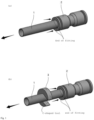
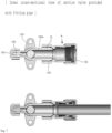
- FIG. 1 illustrates a conventional fitting device.
- the conventional fitting device 2 expands an inner diameter of an inner bore lock washer spring by pressing both ends of the fitting device so as to remove the pipe that has been gripped (or fixed).
- both ends of the fitting device 2 that is, a circular periphery should be continuously pressed until the pipe is released and, if force is applied to only one side of the periphery, an inner diameter of a ring lock washer spring cannot be evenly expanded in overall directions and causes an inconvenience in that the pipe 1 is not easy to remove.
- a C-shaped tool 3 is used as a washer such that the tool is fitted into the pre-inserted pipe 1, followed by evenly applying force to both sides of the circular periphery at the end of the fitting device 2, in order to separate the pipe 1.
- the C-shaped tool 3 should be carried and managed along with different types or pipe diameters of the pipe 1 and, if the C-shaped tool 3 is lost or not carried, there is a problem of considerable inconvenience in removing the pipe 1.
- an element for cooling is used for air conditioning in a cycle of compression-condensation-expansion-evaporation, wherein gas is introduced through a service valve and heat-exchange type air conditioning is performed by interaction between an indoor unit and an outdoor unit.
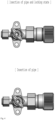
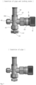
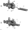
- attachment of a pipe E to a conventional air-conditioning service valve A is implemented using the service valve A and threads of a thread nipple B included in the service valve rather than any fitting device. More particularly, after expanding the pipe E in a trumpet shape (C) by means of an expansion tool, the service valve A and the pipe E are fastened to each other using nuts corresponding to the thread nipple B while tightening and turning the nuts D.
- FIG. 2(b) when the air-conditioning service valve A shown in FIG. 2(a) is installed on the outdoor unit, an inconvenient operation of pipe expansion is required in order to modify the pipe E into a trumpet(C) shape at both of the indoor unit side and the outdoor unit side. Further, in order to fasten the pipe E with a nipple integrally with an evaporator at the indoor unit side, the trumpet-shaped (C) pipe E should be tightened with a monkey spanner using a nut D, which is a cumbersome operation.
- the service valve A at the outdoor unit side has a configuration such that a fluid (gas) is blocked by fitting a hexagonal wrench G into a hexagonal groove of a valve nut F and turning the same, so as to control flow thereof.
- the hexagonal wrench G is a " ⁇ "-shaped wrench but a worker must carry different types and sizes of wrenches.
- the present inventors have invented a fitting device for easy insertion and removal of a pipe and a service valve including the same ( Korean Patent Registration No. 1900927 ) and further proposed a fitting device for easy fastening and dismantling of a pipe in an alternative manner.
- KR 101 900 927 B1 relates to pipe fitting, for example, of pipes and hoses, and more particularly to a service valve including a fitting device for easy insertion and removal of a pipe that is utilized as a cooling/heating cycle air conditioning part.
- US 5 320 326 A provides an improved structure of a quick-connect pipe fitting, and particularly a structure for a quick-connect pipe fitting used to connect a pressure pipe or a hydraulic tubing in a system that comprises a compression member on top of a lock washer such that the compression member is fitted and secured in a base.
- FR 2 893 698 B1 discloses an instantaneous coupling connection for connecting metallic tubes for e.g. hydraulic transmission.
- US 2019/271423 Al relates to mechanical pipe couplings for joining pipe elements.
- a fitting device is provided as set out in claim 1.
- a service valve is provided as set out in claim 2.
- the present disclosure has been devised to overcome the aforementioned problems and reduce accident factors during work, and an object of the present invention is to provide a fitting device for easily, safely and conveniently fastening and dismantling a pipe, as well as a service valve including the same.
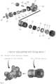
- the present invention provides a service valve including a fitting device, characterized in that a fitting housing 120 may have an outer thread formed by a predetermined length on an outer ring at the other end of the fitting housing, and a first inner boss protruding from the other end at a predetermined depth, in addition, the fitting device 200 may include: a cap handle 50 screwed to the outer thread of the fitting housing 120; a ring lock washer spring 25 seated on the first inner boss; and a sleeve 35 fitted into an inner bore of the other end and interposed between the ring lock washer spring 25 and the cap handle 50, wherein the sleeve 35 moves and presses the ring lock washer spring 25 by rotation of the cap handle 50 to expand a diameter of the inner bore (“inner diameter”), so as to dismantle a pipe
- the fitting housing 120 may include an inner thread formed by a predetermined length at the inner bore of the other end, wherein the first inner boss protrudes from the innermost side of the inner thread and the ring lock washer spring 25 is seated on the first inner boss, and the fitting device 200 may further include a guide ring nut 30 screwed to the inner thread to fix the ring lock washer spring 25.
- the fitting housing 120 may include a second inner boss protruding at a predetermined depth from the first inner boss toward the service valve
- the fitting device 200 may include: a support ring 20 which is seated on the second inner boss and comes into contact with an end of the pre-inserted pipe 165 to block further entry of the pipe 165; and a rubber packing 10 interposed between the support ring 20 and the ring lock washer spring 25, an end of which is tapered to be in contact with tapered teeth protruding from an inner diameter of the ring lock washer spring 25.
- the support ring 20 may include at least one gas inlet perforated on an outer circumference thereof, and the rubber packing 10 may be formed in a tapered tubular shape having an outer diameter increasing toward the service valve, which is provided with a gas compression groove on a thickness surface at the service valve side, wherein a portion of gas introduced from the service valve presses the gas compression groove through the gas inlet, so as to improve air-tightness between the rubber packing 10 and the ring lock washer spring or increase fastening force between the ring lock washer spring 25 and the pipe 165.
- the present invention provides a fitting device 200 capable of dismantling a pipe 165 previously inserted into the fitting device 200, including: a fitting housing 120 which includes an outer thread formed by a predetermined length on an outer ring at the other end thereof and a first inner boss protruding at a predetermined depth from the other end; a cap handle 50 screwed to the outer thread of the fitting housing 120; a ring lock washer spring 25 seated on the first inner boss; and a sleeve 35 which is fitted into an inner bore at the other end of the fitting housing 120 and interposed between the ring lock washer spring 25 and the cap handle 50, wherein the sleeve 35 moves and presses the ring lock washer spring 25 by rotation of the cap handle 50 so as to expand a diameter of the inner bore, that is, an inner diameter.
- the fitting device and the service valve including the same may exhibit effects of fastening or dismantling a pipe only by rotating the cap handle without scratching an outer surface of the pipe, even though a periphery of both ends of the fitting device is not continuously pressed as in the prior art and even if no further tool is carried and used.
- the present invention can control a fluid (gas) by simply turning the valve handle even in a narrow space without loosening the nut.
- Singular expressions may include plural expressions unless the context clearly indicates otherwise.
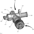
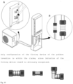
- FIG. 3 illustrates overall appearance of a service valve including a fitting device according to an embodiment of the present invention.
- a fitting device 200 is fastened to one end of the service valve unit 100, wherein a pipe may be installed on the fitting device 200, more particularly, may be inserted into a pipe inlet of a fitting housing 120, and one end of the fitting housing 120 may be fastened to the service valve unit 100 having a valve handle 137 exposed to the outside.
- a base 125 integrally formed with a valve housing 100a illustrated in FIG. 3 may be attached to the outside of an outdoor unit, and a copper pipe 160 may be connected to a coupler of a compressor.
- the fitting device according to one embodiment of the present invention may of course be widely employed in general hydraulic/pneumatic applications or injection fitting applications other than a refrigerating machine.
- FIG. 6 is an exploded perspective view of the service valve including a fitting device according to an embodiment of the present invention.
- the valve housing 100a may be fastened with a valve nut 130 on one side thereof. That is, a thread formed on an inner bore of a coupler formed in one direction of the valve housing 100a is mutually engaged and fastened with another thread formed on an outer ring at one end of the valve nut 130, so that the valve nut 130 is fitted into the valve housing 100a to be installed.
- a circular groove may be formed along an outer circumference in the middle of the valve nut 130, and a valve packing 130a may be fitted into the circular groove.
- a ringshaped guide washer pin 130b which is partially opened may be fitted into a C-shaped groove at an end of the inner bore of the coupler formed in one direction of the valve housing 100a.
- a nut stopper 135 may be fastened while turning around the outer thread at the end of the valve housing 100a such that the valve nut 130 protruding outwardly penetrates a hollow part.
- a valve stopper packing 177 may be interposed between the nut stopper 135 and the valve nut 130.
- the end portion protruding outwardly through the hollow part of the nut stopper 135 has a square shape and is provided with a thread groove on an outer surface thereof, and a handle screw 138 is fastened in the thread groove in a state in which a valve handle 137 having a square groove is fitted, so that the valve nut 130 may rotate in correspondence with rotation of the valve handle 137.
- a fluid stopper nut 155 may be fastened by turning the outer thread of the fluid (GAS) inlet 150a.
- the pin nut 150 may be pressed by an injection nut to introduce the fluid.
- the fitting housing 120 may be fastened to a coupler provided in one direction of the valve housing 100a, as shown in FIG. 3 .
- the coupler in one direction of the valve housing 100a may consist of a nipple 15 and, in order to be coupled to the nipple 15, one end of the fitting housing 120 may have an inner bore formed with a thread by a predetermined length corresponding to the nipple 15 (see FIG. 7 and the like).
- an outer thread may be formed by a predetermined length, to which a cap handle 50 having a thread corresponding to the inner side may be screw-fastened.
- the cap handle 50 may include a thru-hole formed as an entrance in the center portion, through which a pipe 165 is inserted to penetrate the center portion.
- An outer ring of the cap handle may be formed in a sawtooth shape to be easily turned by a hand.
- An inner bore of the cap handle 50 may be engaged and fastened with the outer thread of the fitting housing 120, wherein an end of the cap handle 50 is preferably folded by means of press processing to be caught on the outer thread of the protruding fitting housing 120, thus preventing the cap handle 50 from being released from the fitting housing 120.
- one end of the fitting housing 120 refers to an end of the fitting housing 120, to which the valve housing 100a is coupled.
- the other end of the fitting housing 120 refers to an opposite end thereof, to which the cap handle 50 is coupled.
- the fitting housing 120 may be formed in a straight tubular shape, however, the present invention is not limited thereto. Instead, as shown in FIG. 10 , a variety of shapes such as an L-shape, a Y-shape, etc. may also be applied.
- a sleeve 35 may be fitted into the other end of the fitting housing 120, and the sleeve 35 may move forward or backward according to rotation of the cap handle 50.
- the sleeve 35 may include: a tubular sleeve body with an outer diameter corresponding to an inner diameter of the ring lock washer spring 25; and a wing part with an outer diameter corresponding to the outer diameter of the other end of the fitting housing 120.
- one end 37 of the body of the sleeve 35 may have a sharp-tapered shape while the wing part may be extended to be bent outwardly from the other end of the sleeve body.
- the sleeve 35 may be installed such that the sleeve body is inserted into the other end of the fitting housing 120 and the wing part spans the other end of the fitting housing 120.
- the cap handle 50 rotates in an unlocking direction and moves toward the fitting housing 120
- the wing part of the sleeve 35 is pressed toward the fitting housing side 120 and an end 37 of the body of the sleeve 35 may expand teeth formed along a circumference of the inner bore of the ring lock washer spring 25 (see FIG. 9(a) ).
- the cap handle 50 rotates in a locking direction and moves away from the fitting housing 120, the wing part of the sleeve 35 is not pressed toward the fitting housing side 120 but retracts the sleeve 35 by elastic force of the ring lock washer spring 25 and, at the same time, the inner bore of the ring lock washer spring 25 may be closed to reduce the inner diameter (see FIG. 9 (b) ).
- a length of the sleeve body may be defined such that, when the sleeve 35 is pressed toward the fitting housing 120, a front end of the sleeve 35 reaches the tapered tooth portion of the ring lock washer spring 25.
- the cap handle 50 in order to move the sleeve 35 forward or backward whenever the cap handle 50 moves forward or backward, the cap handle 50 may be formed integrally with the sleeve 35 or may be attached to the sleeve 35.
- the ring lock washer spring 25 positioned in front of the sleeve 35 may include a first inner boss protruding at a predetermined depth from the other end of the fitting housing 120 so as to expand the inner bore without being pushed by a pressure of the sleeve 35.
- the ring lock washer spring 25 specifically, a periphery of the ring lock washer spring 25, is seated, wherein teeth formed on the inner bore of the ring lock washer spring 25 may be arranged to be tapered in a direction parallel to a pressing direction of the sleeve 35 by the cap handle 50.
- the fitting housing 120 may include an inner thread formed by a predetermined length on the inner bore at the other end, and the first inner boss may protrude from the innermost side of the inner thread and the ring lock washer spring 25 is preferably seated on the first inner boss.
- a guide ring nut 30 is preferably screwed to the inner thread so as to press/fix the periphery of the ring lock washer spring 25 seated on the first inner boss.
- the ring lock washer spring 25 seated on the first inner boss is interposed between the first inner boss and the guide ring nut 30, so that the guide ring nut 30 tightened along the inner thread may rigidly fix the ring lock washer spring 25.
- the ring lock washer spring 25 may not move but maintain the original position thereof.
- the sleeve 35 penetrates a hollow part or an inner bore of the guide ring nut 30, and the sleeve 35 may not move forward or backward without interference with the guide ring nut 30.
- the fitting housing 120 may further include a second inner boss protruding at a predetermined depth from the first inner boss in the direction of the service valve unit 100.
- the support ring 20 is seated on the second inner boss wherein the support ring 20 is in contact with an end of the inserted pipe 165 to prevent the pipe 165 from further entering the service valve unit side 100.
- the support ring may include a stepped part 163 to seat the support ring on the second inner boss, and a tubular diameter of the support ring 20 may be different before and after the stepped part 163.
- the support ring 20 may include at least one gas inlet perforated on an outer circumference of the support ring, wherein a space is present in the gas inlet in order to guide gas passing through the gas inlet to a gas compression groove of the rubber packing 10 to be described later.
- the gas inlet may be perforated and formed on the outer circumference of the support ring 20.
- the gas inlet may comprise at least one groove formed in a length direction around the outer circumference of the support ring 20.
- the gas inlet through which the fluid enters may be formed around an outer periphery of the support ring 20, thus easily manufacturing the support ring 20 while reducing production cost.
- the fluid flowing through the gas inlet formed in a length direction of the outer circumference of the support ring 20, as shown in FIG. 13b may directly/indirectly press the rubber packing 10 and the ring lock washer spring 25 in order, and therefore, fastening force between the ring lock washer spring 25 and the pipe 165 may be increased.
- the rubber packing 10 may be interposed between the support ring 20 and the ring lock washer spring 25.
- a portion where the rubber packing 10 is installed that is, a region from the second inner boss to the first inner boss of the fitting housing 120 may have a tapered shape to be gradually narrowed.
- the rubber packing 10 made of an elastic material may also have an outer ring in a tapered tubular shape that becomes narrower toward the first inner boss.
- a gas compression groove is preferably formed on a thickness surface of one end of the rubber packing 10, that is, on the end facing the second inner boss.
- some of the gas introduced through the gas inlet of the support ring 20 may press the rubber packing 10 toward the ring lock washer spring 25 with reference to the gas compression groove as an operating point.
- the rubber packing 10 may be compressed with the ring lock washer spring 25 so as to improve air-tightness between the rubber packing 10 and the ring lock washer spring 25.
- a thickness surface of the other end of the rubber packing 10, that is, the end facing the ring lock washer spring 25, is tapered to be in contact with teeth protruding to be tapered in the ring lock washer spring 25, so as to have a concave shape.
- the end 37 of the body of the sleeve 35 expands the teeth in the inner bore of the ring lock washer spring 25 by the cap handle 50, as in the unlocking state shown in FIG. 8(a) , and therefore, the pipe 165 may be inserted without scratching an outer circumference of the pipe.
- the stepped part 163 formed on the inner bore of the support ring 20 inhibits further entry of the pipe 165, whereby the end of the pipe 165 inserted into the fitting device 200 may contact the stepped part 163.
- the sleeve 35 retracts to reduce a diameter of the expanded inner bore of the ring lock washer spring 25 by the cap handle 50, as in the locking state shown in FIG. 8(a) , and therefore, the teeth are closed to bite the pipe 165 and the pipe 165 may be firmly fixed.
- a rotational direction for moving the cap handle 50 forward and backward may be determined along a direction of threads formed between the cap handle 50 and the fitting housing 120, and the present invention does not particularly limit the direction of the threads between the cap handle 50 and the fitting housing 120.
- the gas fluid may pass through the gas inlet formed on the outer circumference of the support ring 20 (for example, formed in each of four directions) and press the gas compression groove of the rubber packing 10, whereby the rubber packing 10 may be compressed with the ring lock washer spring 25.
- the periphery of the ring lock washer spring 25 may be further air-tightened. The higher the gas pressure, the more air-tightening effects can be expected. Since the rubber packing 10 compresses the tapered portion of the ring lock washer spring 25, air-tightening effects may be maximized.
- the fitting housing 120 may have a display unit A on the outer ring.
- the display unit A is in the form of a colored band, and the color is preferably visible in the locking state while being hidden in the unlocking state by the cap handle 50 to cover the outer ring of the fitting housing 120, whereby the worker can identify the locking state and the unlocking state.
- the display unit A is blue
- the pipe may be inserted in the unlocking state and then switched to the locking state, whereby the pipe 165 can be coupled to the fitting device 200 without damage to an outer surface of the pipe 165. Therefore, a problem of scratching the outer circumference of a pipe when the pipe is inserted into the conventional fitting device may be overcome.
- the teeth of the ring lock washer spring 25 are expanded in the unlocking state and do not interfere with the inserted pipe, thereby causing no problem as in the prior art.
- the rubber packing 10 is compressed to the ring lock washer spring 25 by gas pressure. Therefore, the tapered teeth of the ring lock washer spring 25 are pressed to the pipe 165 to improve fastening force between the ring lock washer spring 25 and the pipe 165.
- the valve handle 137 is gradually locked by starting from a high pressure valve. After the gas is fully exhausted, the valve handle 137 is completely locked at a low pressure valve. Then the cap handle 50 is turned to the right to switch the locking state to the unlocking state, thereby separating the pipe 165 without interference with the ring lock washer spring 25.
Landscapes
- Engineering & Computer Science (AREA)
- General Engineering & Computer Science (AREA)
- Mechanical Engineering (AREA)
- Chemical & Material Sciences (AREA)
- Combustion & Propulsion (AREA)
- Valve Housings (AREA)
- Quick-Acting Or Multi-Walled Pipe Joints (AREA)
Claims (2)
- Anschlussvorrichtung (200), umfassend:eine Ringschloss-Tellerfeder (25), in der ein Rohr (165) in eine innere Bohrung einführbar ist, um darin gekoppelt zu werden;einen Stützring (20), der dazu ausgestaltet ist, mit einem Ende des einführbaren Rohrs (165) in Kontakt zu stehen, um ein weiteres Eindringen des Rohrs (165) zu verhindern, und der wenigstens einen perforierten Gaseinlass umfasst; undeine Gummidichtung (10), die zwischen dem Stützring (20) und der Ringschloss-Tellerfeder (25) angeordnet ist, wobei ein Ende davon derart verjüngt ist, dass es mit Zähnen in Kontakt steht, die derart verjüngt sind, dass sie die innere Bohrung der Ringschloss-Tellerfeder (25) verjüngen,wobei auf die Gummidichtung (10) durch ein durch den Gaseinlass eingeleitetes Fluid Druck ausgeübt wird, um eine Luftdichtigkeit zwischen der Gummidichtung (10) und der Ringschloss-Tellerfeder (25) zu verbessern oder eine Befestigungskraft zwischen der Ringschloss-Tellerfeder (25) und dem Rohr (165) zu verstärken.
- Serviceventil, umfassend eine Serviceventileinheit (100) und eine Anschlussvorrichtung (200) nach Anspruch 1, wobei die Anschlussvorrichtung (200) mit einem Anschlussgehäuse (120) versehen ist, das an einem Ende des Anschlussgehäuses (120) an die Serviceventileinheit (100) gekoppelt ist.
Applications Claiming Priority (2)
| Application Number | Priority Date | Filing Date | Title |
|---|---|---|---|
| KR1020190120868A KR102098775B1 (ko) | 2019-09-30 | 2019-09-30 | 피팅 장치 및 이를 포함한 서비스밸브 |
| PCT/KR2020/011059 WO2021066320A1 (ko) | 2019-09-30 | 2020-08-19 | 피팅 장치 및 이를 포함한 서비스밸브 |
Publications (4)
| Publication Number | Publication Date |
|---|---|
| EP4043774A1 EP4043774A1 (de) | 2022-08-17 |
| EP4043774A4 EP4043774A4 (de) | 2023-10-11 |
| EP4043774B1 true EP4043774B1 (de) | 2025-02-12 |
| EP4043774C0 EP4043774C0 (de) | 2025-02-12 |
Family
ID=70275653
Family Applications (1)
| Application Number | Title | Priority Date | Filing Date |
|---|---|---|---|
| EP20872429.4A Active EP4043774B1 (de) | 2019-09-30 | 2020-08-19 | Anschlussvorrichtung und damit versehenes serviceventil |
Country Status (6)
| Country | Link |
|---|---|
| US (1) | US11788639B2 (de) |
| EP (1) | EP4043774B1 (de) |
| JP (1) | JP7310017B2 (de) |
| KR (1) | KR102098775B1 (de) |
| CN (2) | CN112576846B (de) |
| WO (1) | WO2021066320A1 (de) |
Families Citing this family (3)
| Publication number | Priority date | Publication date | Assignee | Title |
|---|---|---|---|---|
| KR102098775B1 (ko) * | 2019-09-30 | 2020-04-08 | 민병수 | 피팅 장치 및 이를 포함한 서비스밸브 |
| CN116772000B (zh) * | 2023-08-03 | 2025-07-25 | 抚州市银圣王洁具有限公司 | 一种水龙头稳定对接设备 |
| KR102704015B1 (ko) | 2023-12-04 | 2024-09-06 | 민병수 | 피팅 장치 및 이를 포함한 서비스밸브 |
Family Cites Families (16)
| Publication number | Priority date | Publication date | Assignee | Title |
|---|---|---|---|---|
| GB756608A (en) * | 1953-11-06 | 1956-09-05 | Snap Tite Inc | Quick detachable pipe couplers |
| JPS6044683A (ja) * | 1983-08-23 | 1985-03-09 | 株式会社日本ピスコ | 管継手 |
| US5320326A (en) * | 1993-06-11 | 1994-06-14 | Ted Ju | Improved structure of a quick-connect pipe fitting |
| JPH08145516A (ja) * | 1994-11-15 | 1996-06-07 | Mitsubishi Heavy Ind Ltd | 冷凍機用サービスバルブ |
| JP2001208266A (ja) * | 2000-01-20 | 2001-08-03 | Nippon Kokan Pipe Fittings Mfg Co Ltd | 差込み式管継手 |
| FR2893698B1 (fr) * | 2005-11-18 | 2009-02-27 | Legris Sa | Raccord a couplage instantane |
| US8474877B2 (en) * | 2007-09-19 | 2013-07-02 | Bridgeport Fittings, Inc. | Push-in fitting for electrical metallic tubing with enhanced sealing and continuity |
| JP5323594B2 (ja) | 2009-07-02 | 2013-10-23 | 東尾メック株式会社 | 管継手用抜止めリング |
| CN102121550B (zh) | 2010-09-29 | 2015-05-27 | 拉卡萨安吉拉股份有限公司 | 管道快速连接方法及使用该方法的接头 |
| WO2014051298A1 (ko) * | 2012-09-28 | 2014-04-03 | Kim Byung Sub | 가압식 패킹부재를 이용한 배관 커플러 |
| KR101440223B1 (ko) | 2013-03-25 | 2014-09-15 | 박길승 | 에어컨 냉매관 연결용 서비스 밸브 |
| KR101618639B1 (ko) * | 2013-12-23 | 2016-05-09 | (주)로커스 | 공기조화기용 서비스 밸브 어셈블리 |
| MX2018005466A (es) * | 2015-11-02 | 2018-11-09 | Liqui Box Corp | Montaje de pico vertedor-conectador para la dispensacion de fluidos desde bolsas flexibles. |
| US10859190B2 (en) * | 2016-05-16 | 2020-12-08 | Victaulic Company | Sprung coupling |
| KR101900927B1 (ko) | 2018-05-09 | 2018-09-21 | 민병수 | 파이프 삽입 및 제거가 용이한 피팅 장치와 이를 포함하는 서비스밸브 |
| KR102098775B1 (ko) * | 2019-09-30 | 2020-04-08 | 민병수 | 피팅 장치 및 이를 포함한 서비스밸브 |
-
2019
- 2019-09-30 KR KR1020190120868A patent/KR102098775B1/ko active Active
-
2020
- 2020-08-19 EP EP20872429.4A patent/EP4043774B1/de active Active
- 2020-08-19 JP JP2022520005A patent/JP7310017B2/ja active Active
- 2020-08-19 WO PCT/KR2020/011059 patent/WO2021066320A1/ko not_active Ceased
- 2020-08-19 US US17/050,839 patent/US11788639B2/en active Active
- 2020-09-30 CN CN202011057955.2A patent/CN112576846B/zh active Active
- 2020-09-30 CN CN202022219496.5U patent/CN214171642U/zh not_active Expired - Fee Related
Also Published As
| Publication number | Publication date |
|---|---|
| WO2021066320A1 (ko) | 2021-04-08 |
| US11788639B2 (en) | 2023-10-17 |
| EP4043774A1 (de) | 2022-08-17 |
| CN112576846B (zh) | 2023-04-07 |
| CN214171642U (zh) | 2021-09-10 |
| CN112576846A (zh) | 2021-03-30 |
| EP4043774A4 (de) | 2023-10-11 |
| JP7310017B2 (ja) | 2023-07-18 |
| US20220221077A1 (en) | 2022-07-14 |
| JP2022551247A (ja) | 2022-12-08 |
| EP4043774C0 (de) | 2025-02-12 |
| KR102098775B1 (ko) | 2020-04-08 |
Similar Documents
| Publication | Publication Date | Title |
|---|---|---|
| EP4043774B1 (de) | Anschlussvorrichtung und damit versehenes serviceventil | |
| AU2008298279B2 (en) | Duplex pipe fitting, exclusive tool for the duplex pipe fitting, refrigeration system employing the duplex pipe fitting, and separation type air conditioner | |
| JP5457579B2 (ja) | ホースクランプ用トルクコントロールボルト{torquecontrolboltforhoseclamp} | |
| EP2492568B1 (de) | Schliessventil | |
| KR102817345B1 (ko) | 분해 방지 조인트 및 분해 방지 조인트 어셈블리 | |
| JP3939311B2 (ja) | 管継手 | |
| EP2480813B1 (de) | Sicherheitsmuffe für eine rohrverbindung | |
| JP4145183B2 (ja) | 管継手 | |
| EP1543266B1 (de) | Schnellverbindung für einen mit gewinde versehener fluidbauteil | |
| KR102056883B1 (ko) | 피팅 장치 및 이를 포함한 서비스밸브 | |
| US6453517B1 (en) | Fastening clamp for joint portion of oblong hoses | |
| KR102815098B1 (ko) | 분해 방지 연결 부재, 분해 방지 연결 어셈블리 및 공조 장치 | |
| US3476411A (en) | Panel coupling having means for preventing axial and rotational movement | |
| EP3395503A1 (de) | Steckschlüsseleinsatz für ein feuerhydrantventil | |
| KR100555145B1 (ko) | 상수도관 연결구조 | |
| JP5395971B2 (ja) | 管継手及び閉鎖バルブ | |
| KR102739787B1 (ko) | 분해 방지 너트 어셈블리 및 공조 시스템 | |
| CN211715967U (zh) | 防拆螺母组件及空调系统 | |
| CN211738304U (zh) | 防拆螺母组件及空调系统 | |
| JP7572831B2 (ja) | 水道用サドル付分水栓 | |
| CN120194158A (zh) | 一种阀装置及阀装置的制造方法 | |
| JP5359087B2 (ja) | 食い込み式管接続構造、弁、食い込み式管継手及び冷凍装置 | |
| KR100413667B1 (ko) | 가스밸브 | |
| AU2007202374A1 (en) | Access fitting | |
| JPH0242159B2 (de) |
Legal Events
| Date | Code | Title | Description |
|---|---|---|---|
| STAA | Information on the status of an ep patent application or granted ep patent |
Free format text: STATUS: THE INTERNATIONAL PUBLICATION HAS BEEN MADE |
|
| PUAI | Public reference made under article 153(3) epc to a published international application that has entered the european phase |
Free format text: ORIGINAL CODE: 0009012 |
|
| STAA | Information on the status of an ep patent application or granted ep patent |
Free format text: STATUS: REQUEST FOR EXAMINATION WAS MADE |
|
| 17P | Request for examination filed |
Effective date: 20220429 |
|
| AK | Designated contracting states |
Kind code of ref document: A1 Designated state(s): AL AT BE BG CH CY CZ DE DK EE ES FI FR GB GR HR HU IE IS IT LI LT LU LV MC MK MT NL NO PL PT RO RS SE SI SK SM TR |
|
| DAV | Request for validation of the european patent (deleted) | ||
| DAX | Request for extension of the european patent (deleted) | ||
| A4 | Supplementary search report drawn up and despatched |
Effective date: 20230912 |
|
| RIC1 | Information provided on ipc code assigned before grant |
Ipc: F24F 1/32 20110101ALI20230906BHEP Ipc: F16L 43/00 20060101ALI20230906BHEP Ipc: F16L 37/091 20060101ALI20230906BHEP Ipc: F16L 37/098 20060101ALI20230906BHEP Ipc: F16L 37/28 20060101ALI20230906BHEP Ipc: F16L 37/22 20060101ALI20230906BHEP Ipc: F16L 41/14 20060101ALI20230906BHEP Ipc: F16L 41/02 20060101ALI20230906BHEP Ipc: F16L 41/12 20060101ALI20230906BHEP Ipc: F16L 41/16 20060101AFI20230906BHEP |
|
| GRAP | Despatch of communication of intention to grant a patent |
Free format text: ORIGINAL CODE: EPIDOSNIGR1 |
|
| STAA | Information on the status of an ep patent application or granted ep patent |
Free format text: STATUS: GRANT OF PATENT IS INTENDED |
|
| RIC1 | Information provided on ipc code assigned before grant |
Ipc: F24F 1/32 20110101ALI20240822BHEP Ipc: F16L 43/00 20060101ALI20240822BHEP Ipc: F16L 37/091 20060101ALI20240822BHEP Ipc: F16L 37/098 20060101ALI20240822BHEP Ipc: F16L 37/28 20060101ALI20240822BHEP Ipc: F16L 37/22 20060101ALI20240822BHEP Ipc: F16L 41/14 20060101ALI20240822BHEP Ipc: F16L 41/02 20060101ALI20240822BHEP Ipc: F16L 41/12 20060101ALI20240822BHEP Ipc: F16L 41/16 20060101AFI20240822BHEP |
|
| INTG | Intention to grant announced |
Effective date: 20240903 |
|
| GRAS | Grant fee paid |
Free format text: ORIGINAL CODE: EPIDOSNIGR3 |
|
| GRAA | (expected) grant |
Free format text: ORIGINAL CODE: 0009210 |
|
| STAA | Information on the status of an ep patent application or granted ep patent |
Free format text: STATUS: THE PATENT HAS BEEN GRANTED |
|
| AK | Designated contracting states |
Kind code of ref document: B1 Designated state(s): AL AT BE BG CH CY CZ DE DK EE ES FI FR GB GR HR HU IE IS IT LI LT LU LV MC MK MT NL NO PL PT RO RS SE SI SK SM TR |
|
| REG | Reference to a national code |
Ref country code: GB Ref legal event code: FG4D |
|
| REG | Reference to a national code |
Ref country code: CH Ref legal event code: EP |
|
| REG | Reference to a national code |
Ref country code: DE Ref legal event code: R096 Ref document number: 602020046096 Country of ref document: DE |
|
| REG | Reference to a national code |
Ref country code: IE Ref legal event code: FG4D |
|
| U01 | Request for unitary effect filed |
Effective date: 20250310 |
|
| U07 | Unitary effect registered |
Designated state(s): AT BE BG DE DK EE FI FR IT LT LU LV MT NL PT RO SE SI Effective date: 20250318 |
|
| PG25 | Lapsed in a contracting state [announced via postgrant information from national office to epo] |
Ref country code: RS Free format text: LAPSE BECAUSE OF FAILURE TO SUBMIT A TRANSLATION OF THE DESCRIPTION OR TO PAY THE FEE WITHIN THE PRESCRIBED TIME-LIMIT Effective date: 20250512 |
|
| PG25 | Lapsed in a contracting state [announced via postgrant information from national office to epo] |
Ref country code: PL Free format text: LAPSE BECAUSE OF FAILURE TO SUBMIT A TRANSLATION OF THE DESCRIPTION OR TO PAY THE FEE WITHIN THE PRESCRIBED TIME-LIMIT Effective date: 20250212 |
|
| PG25 | Lapsed in a contracting state [announced via postgrant information from national office to epo] |
Ref country code: ES Free format text: LAPSE BECAUSE OF FAILURE TO SUBMIT A TRANSLATION OF THE DESCRIPTION OR TO PAY THE FEE WITHIN THE PRESCRIBED TIME-LIMIT Effective date: 20250212 |
|
| PG25 | Lapsed in a contracting state [announced via postgrant information from national office to epo] |
Ref country code: IS Free format text: LAPSE BECAUSE OF FAILURE TO SUBMIT A TRANSLATION OF THE DESCRIPTION OR TO PAY THE FEE WITHIN THE PRESCRIBED TIME-LIMIT Effective date: 20250612 Ref country code: NO Free format text: LAPSE BECAUSE OF FAILURE TO SUBMIT A TRANSLATION OF THE DESCRIPTION OR TO PAY THE FEE WITHIN THE PRESCRIBED TIME-LIMIT Effective date: 20250512 |
|
| PG25 | Lapsed in a contracting state [announced via postgrant information from national office to epo] |
Ref country code: HR Free format text: LAPSE BECAUSE OF FAILURE TO SUBMIT A TRANSLATION OF THE DESCRIPTION OR TO PAY THE FEE WITHIN THE PRESCRIBED TIME-LIMIT Effective date: 20250212 |
|
| PG25 | Lapsed in a contracting state [announced via postgrant information from national office to epo] |
Ref country code: GR Free format text: LAPSE BECAUSE OF FAILURE TO SUBMIT A TRANSLATION OF THE DESCRIPTION OR TO PAY THE FEE WITHIN THE PRESCRIBED TIME-LIMIT Effective date: 20250513 |
|
| U20 | Renewal fee for the european patent with unitary effect paid |
Year of fee payment: 6 Effective date: 20250825 |
|
| PG25 | Lapsed in a contracting state [announced via postgrant information from national office to epo] |
Ref country code: SM Free format text: LAPSE BECAUSE OF FAILURE TO SUBMIT A TRANSLATION OF THE DESCRIPTION OR TO PAY THE FEE WITHIN THE PRESCRIBED TIME-LIMIT Effective date: 20250212 |
|
| PG25 | Lapsed in a contracting state [announced via postgrant information from national office to epo] |
Ref country code: CZ Free format text: LAPSE BECAUSE OF FAILURE TO SUBMIT A TRANSLATION OF THE DESCRIPTION OR TO PAY THE FEE WITHIN THE PRESCRIBED TIME-LIMIT Effective date: 20250212 |
|
| PG25 | Lapsed in a contracting state [announced via postgrant information from national office to epo] |
Ref country code: SK Free format text: LAPSE BECAUSE OF FAILURE TO SUBMIT A TRANSLATION OF THE DESCRIPTION OR TO PAY THE FEE WITHIN THE PRESCRIBED TIME-LIMIT Effective date: 20250212 |