EP1543266B1 - Schnellverbindung für einen mit gewinde versehener fluidbauteil - Google Patents
Schnellverbindung für einen mit gewinde versehener fluidbauteil Download PDFInfo
- Publication number
- EP1543266B1 EP1543266B1 EP03754643A EP03754643A EP1543266B1 EP 1543266 B1 EP1543266 B1 EP 1543266B1 EP 03754643 A EP03754643 A EP 03754643A EP 03754643 A EP03754643 A EP 03754643A EP 1543266 B1 EP1543266 B1 EP 1543266B1
- Authority
- EP
- European Patent Office
- Prior art keywords
- fluid
- quick connector
- housing
- fluid component
- retainer
- Prior art date
- Legal status (The legal status is an assumption and is not a legal conclusion. Google has not performed a legal analysis and makes no representation as to the accuracy of the status listed.)
- Expired - Lifetime
Links
- 239000012530 fluid Substances 0.000 title claims description 88
- 238000009428 plumbing Methods 0.000 description 4
- 239000004677 Nylon Substances 0.000 description 2
- 230000006835 compression Effects 0.000 description 2
- 238000007906 compression Methods 0.000 description 2
- 230000014759 maintenance of location Effects 0.000 description 2
- 239000002184 metal Substances 0.000 description 2
- 230000004048 modification Effects 0.000 description 2
- 238000012986 modification Methods 0.000 description 2
- 229920001778 nylon Polymers 0.000 description 2
- 238000000926 separation method Methods 0.000 description 2
- 230000007704 transition Effects 0.000 description 2
- XLYOFNOQVPJJNP-UHFFFAOYSA-N water Substances O XLYOFNOQVPJJNP-UHFFFAOYSA-N 0.000 description 2
- 229910000639 Spring steel Inorganic materials 0.000 description 1
- 230000000694 effects Effects 0.000 description 1
- 239000000446 fuel Substances 0.000 description 1
- 238000003780 insertion Methods 0.000 description 1
- 230000037431 insertion Effects 0.000 description 1
- 238000009434 installation Methods 0.000 description 1
- 239000004033 plastic Substances 0.000 description 1
- 229920001470 polyketone Polymers 0.000 description 1
Images

Classifications
-
- F—MECHANICAL ENGINEERING; LIGHTING; HEATING; WEAPONS; BLASTING
- F16—ENGINEERING ELEMENTS AND UNITS; GENERAL MEASURES FOR PRODUCING AND MAINTAINING EFFECTIVE FUNCTIONING OF MACHINES OR INSTALLATIONS; THERMAL INSULATION IN GENERAL
- F16L—PIPES; JOINTS OR FITTINGS FOR PIPES; SUPPORTS FOR PIPES, CABLES OR PROTECTIVE TUBING; MEANS FOR THERMAL INSULATION IN GENERAL
- F16L25/00—Construction or details of pipe joints not provided for in, or of interest apart from, groups F16L13/00 - F16L23/00
- F16L25/009—Combination of a quick-acting type coupling and a conventional one
-
- F—MECHANICAL ENGINEERING; LIGHTING; HEATING; WEAPONS; BLASTING
- F16—ENGINEERING ELEMENTS AND UNITS; GENERAL MEASURES FOR PRODUCING AND MAINTAINING EFFECTIVE FUNCTIONING OF MACHINES OR INSTALLATIONS; THERMAL INSULATION IN GENERAL
- F16L—PIPES; JOINTS OR FITTINGS FOR PIPES; SUPPORTS FOR PIPES, CABLES OR PROTECTIVE TUBING; MEANS FOR THERMAL INSULATION IN GENERAL
- F16L37/00—Couplings of the quick-acting type
- F16L37/08—Couplings of the quick-acting type in which the connection between abutting or axially overlapping ends is maintained by locking members
- F16L37/084—Couplings of the quick-acting type in which the connection between abutting or axially overlapping ends is maintained by locking members combined with automatic locking
- F16L37/098—Couplings of the quick-acting type in which the connection between abutting or axially overlapping ends is maintained by locking members combined with automatic locking by means of flexible hooks
- F16L37/0985—Couplings of the quick-acting type in which the connection between abutting or axially overlapping ends is maintained by locking members combined with automatic locking by means of flexible hooks the flexible hook extending radially inwardly from an outer part and engaging a bead, recess or the like on an inner part
-
- Y—GENERAL TAGGING OF NEW TECHNOLOGICAL DEVELOPMENTS; GENERAL TAGGING OF CROSS-SECTIONAL TECHNOLOGIES SPANNING OVER SEVERAL SECTIONS OF THE IPC; TECHNICAL SUBJECTS COVERED BY FORMER USPC CROSS-REFERENCE ART COLLECTIONS [XRACs] AND DIGESTS
- Y10—TECHNICAL SUBJECTS COVERED BY FORMER USPC
- Y10T—TECHNICAL SUBJECTS COVERED BY FORMER US CLASSIFICATION
- Y10T29/00—Metal working
- Y10T29/49—Method of mechanical manufacture
- Y10T29/49428—Gas and water specific plumbing component making
-
- Y—GENERAL TAGGING OF NEW TECHNOLOGICAL DEVELOPMENTS; GENERAL TAGGING OF CROSS-SECTIONAL TECHNOLOGIES SPANNING OVER SEVERAL SECTIONS OF THE IPC; TECHNICAL SUBJECTS COVERED BY FORMER USPC CROSS-REFERENCE ART COLLECTIONS [XRACs] AND DIGESTS
- Y10—TECHNICAL SUBJECTS COVERED BY FORMER USPC
- Y10T—TECHNICAL SUBJECTS COVERED BY FORMER US CLASSIFICATION
- Y10T29/00—Metal working
- Y10T29/53—Means to assemble or disassemble
- Y10T29/53987—Tube, sleeve or ferrule
Definitions
- the invention refers to a fluid quick connector according to the features of the preamble of claim 1 as known from GB-A-1 494 984.
- Compression fittings are a typical threaded plumbing connection found in widespread use for home and building water connections.
- Fluid quick connectors are employed in other applications, such as vehicle fuel and air lines, to provide rapid assembly of multiple fluid conduits to each other and/or to fluid use devices, such as pumps, air cylinders, valves, brake cylinders, etc.
- Such fluid quick connectors make use of a housing which receive an endform on another component in a through bore extending through the housing.
- a retainer is insertable into the housing, either axially from an open first end of the through bore in the housing or transversely in the case of a radially displacable retainer through a transverse bore formed in the housing which intersects the through bore.
- Such fluid quick connectors have proven an efficient means to provide rapid assembly of fluid components with a high pull-out retention force and without the need for special tools or time consuming threading operation.
- the present invention is a fluid quick connector having the features of claim 1.
- the quick connector includes is adapted for connecting a first fluid component to a second fluid component, the second fluid component having external threads surrounding a fluid flow port.
- the quick connector includes a housing have a through bore extending between first and second ends, the first end adapted for connection to the first fluid component.
- the second end of the housing has a bore portion adapted to be mounted over threads on a fluid port of the second fluid component.
- a retainer element carried in the housing and engagable with the threads on the second fluid component to connect the housing and the first fluid component to the second fluid component.
- the retainer is separate from the housing.
- the retainer includes a one piece body having an end portion defining an aperture and at least one resilient outer leg projecting from the end portion and terminating in a tip at the end of an inner leg extending angularly inward from an opposite end of the outer leg. The tip end of the inner leg is adapted for engagement with the threads on the second fluid component.
- the housing has an end portion opening to an expanded internal cavity carrying the retainer. At least one aperture is formed in the end portion of the housing opening to the through bore in the retainer in the housing to allow access to the retainer for separation of the quick connect from the fluid component.
- the retainer includes at least one and preferably a plurality of spaced tabs projecting radially inward from an inner surface of the housing into the bore in the housing and adapted to threadingly engage the threads on the fluid component.
- the fluid quick connector of the present invention is uniquely usable with existing or conventional threaded plumbing components using a threaded or compression fitting to effect a joint between two fluid components, such as a valve and a tube, etc.
- the fluid quick connector of the present invention is mountable on the threads of the fluid component for easy and quick connection of another fluid component, such as a tube, to the threaded fluid component as well as providing this capability without requiring any modification to the threaded fluid component.
- the fluid quick connector of the present invention can be any fluid component including valves, such as a stop valve shown by example only in the following drawing, fluid use devices, such as faucets, pumps, as well as fluid conduits themselves.
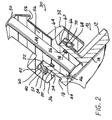
- a fluid component 10 is depicted.
- the fluid component 10 is illustrated as being in the form of a stop valve having a body 12 with a through bore 14 extending from a first end 16.
- the bore 14 extends through the interior of body 12 to a port 18 which has externally disposed threads 20 extending along the port 18 to an outer or distal end 22.
- a valve operator may be mounted on the body 12 at a location opposite from the first end 16 to control the flow of fluid, such as water, between the port 18 and the bore 14 in a known manner.
- a fluid quick connector 30 is mountable by on the external threads 20 of the port 18 of the fluid component or stop valve 10.
- the fluid quick connector 30 includes a generally one piece body formed of metal or a suitable plastic, such as nylon, filled nylon, polyketone, etc.
- the fluid quick connector 30 includes an enlarged body 32 having a bore 34 extending axially inward from a first end 36.
- An aperture or bore 38 is also formed in the body 32 transversely to and intersecting the bore 34 as shown in Figs. 1 and 2.
- the bore 38 preferably extends completely through the body 32 so as to define open portions on opposite sides of the bore 34.
- the aperture or bore 38 defines an opening to the interior of the body 34 to provide access for a release tool, not shown, used to disengage a retainer, described hereafter, from the threads 20 to enable disengagement of the quick connector 30 from the fluid component 10, as also described in greater detail hereafter.
- the bore 34 preferably expands to a larger diameter inner portion 40 before terminating in an inner wall 42.
- the bore 34 is preferably annular and concentric about an inner stem portion 44 extending from a first end 46 through the inner wall 42.
- a fluid through bore 48 extends from the first end 46 of the stem 44 preferably to an opposite or second end 50 of the fluid quick connector 30.
- the bore 34 in cooperation with the stem 44 and an outer wall portion 52 of the body 32 define an interior chamber with an inward extending lip or flange 54 adjacent the first end 36 of the body 32 which is adapted to receive a retaining means or retainer 60.
- the remainder of the fluid quick connector 30 includes an outer stem portion 56 through which an end portion of the fluid bore 68 extends to the second or distal end 50 of the fluid quick connector body 32. At least one or more radially extending projections in the form of barbs 58 may be formed adjacent the distal end 50 of the outer stem 56 to act as a retention means to fixedly and sealingly mount a fluid flexible conduit, not shown, on the outer stem 58 in fluid communication with the fluid bore 48 in the body 32 of the fluid quick connector 30 and the bore 14 in the fluid component 10.
- a radially outward opening, annular groove 78 is formed on the stem 44 intermediate the ends 46 and 50.
- a seal member 76 such as an O-ring, is mounted in the groove 78 to seal the port 18 to the stem 44.
- the retainer 60 is preferably in the form of a one piece member of spring steel or other metal having an annular end 62 surrounding an end aperture 64.
- An outer leg 66 extends angularly from the outer circumference of the annular end portion 60 and terminates in a radially and angularly inward directed leg 68 which terminates in a tip 70.
- installation of the fluid quick connector 30 on the fluid component 10 is begun by pre-mounting the retainer 60 in the interior chamber in the body 32 of the fluid quick connector 30.
- the angular opposed outer and inner legs 68 and 66 of the retainer60 are urged radially inward toward each other to enable the outer diametrical ends at the transition of the outer leg 66 to the inner leg 68 of each leg pair to slide through the open end of the bore 34 until the retainer 60 is inserted sufficiently through the bore 34 to enable the legs 66 and 68 to expand radially outward into the interior chamber formed in the expanded portion 40 of the bore 34.
- the fluid quick connector 30 is then inserted over the distal end 22 of the port 18 of the fluid component 10. Due to the larger diameter of the open end 34 of the bore 30 as compared to the smaller outer diameter of the threads 20 on the port 18. During such insertion, the tip 70 on each leg pair of the retainer will engage the threads 20. Due to the resilient nature of the angularly disposed outer leg 66 and inner leg 68 of each retainer leg pair, the tip 70 on each leg pair will ride radially inward and outward along the threads 20 until the body 32 is inserted sufficiently over the length of the port 18 to bring the inner wall 42 of the body 32 in engagement against the end portion 62 of the retainer and the distal end 22 of the port 18. In this position, the tip end 70 of each retainer leg pair will fixedly and securely engage one of the threads 20 on the port 18 locking the fluid quick connector 30 onto the port 18 and preventing axial separation of the connector 30 from the port 18.
- Disengagement of the fluid quick connector 30 from the fluid component 10 may be effected by a release tool, such as a pair of screwdrivers or pointed end pliers which are urged through one of the ends of the transverse bore 38 in the body 32 to radially urge the tips 70 of the each retainer leg pair outward and away from engagement with the threads 20.
- a release tool such as a pair of screwdrivers or pointed end pliers which are urged through one of the ends of the transverse bore 38 in the body 32 to radially urge the tips 70 of the each retainer leg pair outward and away from engagement with the threads 20.
- the body 32 is urged axially over the port 18 until it is fully separated from the port 18.
Landscapes
- Engineering & Computer Science (AREA)
- General Engineering & Computer Science (AREA)
- Mechanical Engineering (AREA)
- Quick-Acting Or Multi-Walled Pipe Joints (AREA)
Claims (4)
- Eine Schnellverbindung (30), angepasst zum Anschließen eines ersten Fluidbauteils (10) an einen zweiten Fluidbauteil, wobei der erste Fluidbauteil (10) ein Außengewinde (20) besitzt, das eine Fluiddurchflussöffnung (18) umgibt, und die Schnellverbindung (30) aufweist:- ein Gehäuse (32) mit einer Durchgangsbohrung (48), die zwischen einem ersten und einem zweiten Ende (50, 46) verläuft, wobei das erste Ende (50) zum Anschließen an einen zweiten Fluidbauteil angepasst ist;- das zweite Ende (46) des Gehäuses (32) mit einem Bohrungsteil (34), der für die Montage über das Gewinde (20) auf der Fluidöffnung (18) des ersten Fluidbauteils angepasst ist; und- eine Haltevorrichtung (60), die in das Gehäuse (32) eingesetzt ist und in das Gewinde (20) auf dem ersten Fluidbauteil (10) eingreifen kann, um das Gehäuse mit dem ersten Fluidbauteil (10) zu verbinden, ,dadurch gekennzeichnet, dass
die Haltevorrichtung (60) einen einteiligen Körper besitzt, der ein Endstück (62), das eine Öffnung (64) definiert, und mindestens einen federnden Außenschenkel (66) aufweist, der vom Endstück (62) vorspringt und in einer Spitze (70) an einem Ende eines Innenschenkels (68), der sich von einem gegenüberliegenden Ende des Außenschenkels (66) winklig einwärts erstreckt, endet, wobei das Ende der Spitze (70) des Innenschenkels (68) für das Eingreifen in das Gewinde (20) auf dem ersten Fluidbauteil (10) angepasst ist. - Schnellverbindung gemäß Anspruch 1, dadurch gekennzeichnet, dass die Haltevorrichtung (60) vom Gehäuse (32) getrennt ist.
- Schnellverbindung gemäß Anspruch 1 oder 2, dadurch gekennzeichnet, dass das Gehäuse einen Endteil (36) mit einem inneren Hohlraum (40), in den die Haltevorrichtung (60) eingesetzt ist, aufweist.
- Schnellverbindung gemäß einem der Ansprüche 1 bis 3, außerdem aufweisend mindestens eine Bohrung (38), die im Endteil (36) des Gehäuses (32) gebildet wird, mit Öffnung zur Durchgangsbohrung im Gehäuse, um den Zugang zur Haltevorrichtung (60) zu erlauben.
Applications Claiming Priority (3)
| Application Number | Priority Date | Filing Date | Title |
|---|---|---|---|
| US245066 | 2002-09-17 | ||
| US10/245,066 US7108296B2 (en) | 2002-09-17 | 2002-09-17 | Fluid quick connector for threaded fluid components |
| PCT/US2003/029113 WO2004027308A1 (en) | 2002-09-17 | 2003-09-16 | Fluid quick connector for threaded fluid components |
Publications (2)
| Publication Number | Publication Date |
|---|---|
| EP1543266A1 EP1543266A1 (de) | 2005-06-22 |
| EP1543266B1 true EP1543266B1 (de) | 2006-07-12 |
Family
ID=31992029
Family Applications (1)
| Application Number | Title | Priority Date | Filing Date |
|---|---|---|---|
| EP03754643A Expired - Lifetime EP1543266B1 (de) | 2002-09-17 | 2003-09-16 | Schnellverbindung für einen mit gewinde versehener fluidbauteil |
Country Status (6)
| Country | Link |
|---|---|
| US (1) | US7108296B2 (de) |
| EP (1) | EP1543266B1 (de) |
| JP (1) | JP2005539183A (de) |
| AU (1) | AU2003272462A1 (de) |
| DE (1) | DE60306786T2 (de) |
| WO (1) | WO2004027308A1 (de) |
Families Citing this family (9)
| Publication number | Priority date | Publication date | Assignee | Title |
|---|---|---|---|---|
| US7568737B2 (en) | 2006-09-22 | 2009-08-04 | Eaton Corporation | Male coupling for connecting to female threaded coupling |
| CA122002S (en) * | 2007-02-23 | 2008-12-03 | Applica Gmbh | Connector for hoses for a medical pump |
| US8441361B2 (en) * | 2010-02-13 | 2013-05-14 | Mcallister Technologies, Llc | Methods and apparatuses for detection of properties of fluid conveyance systems |
| US8312759B2 (en) * | 2009-02-17 | 2012-11-20 | Mcalister Technologies, Llc | Methods, devices, and systems for detecting properties of target samples |
| US9828835B2 (en) * | 2013-01-24 | 2017-11-28 | Baker Hughes, A Ge Company, Llc | Expansion joint with one way movement feature |
| GB2534364B (en) * | 2015-01-19 | 2020-10-21 | Vent Axia Group Ltd | Mechanical ventilation and heat recovery unit |
| USD921855S1 (en) * | 2019-10-23 | 2021-06-08 | J.Juan S.A.U. | Connector for fluids |
| US20250271084A1 (en) * | 2024-02-27 | 2025-08-28 | Barry Lee Ward, JR. | Adapter for a control stop of a flushometer |
| CN120176932B (zh) * | 2025-05-22 | 2025-08-08 | 玉环江宏机械有限公司 | 制动钳密封测试用快速连接管 |
Family Cites Families (18)
| Publication number | Priority date | Publication date | Assignee | Title |
|---|---|---|---|---|
| US175562A (en) * | 1876-04-04 | Improvement in screw-threads | ||
| US963248A (en) * | 1909-02-26 | 1910-07-05 | Daniel S Ramelli | Pipe-fitting. |
| US3224800A (en) * | 1963-05-13 | 1965-12-21 | Up Right Inc | Adjustable supporting leg |
| US3390898A (en) | 1965-03-22 | 1968-07-02 | Kunio A. Sumida | Quick release threaded coupling |
| US3394950A (en) | 1967-08-09 | 1968-07-30 | Warren R. Jensen | Hose coupling attachment |
| US3603621A (en) * | 1969-10-27 | 1971-09-07 | Frederick L Parsons | Hose coupling |
| US4066282A (en) * | 1974-10-23 | 1978-01-03 | Vann Roy Randell | Positive tubing release coupling |
| DE2632156A1 (de) | 1975-07-18 | 1977-02-03 | Olin Corp | Kupplungsvorrichtung |
| US4265470A (en) * | 1979-09-21 | 1981-05-05 | Cameron Iron Works, Inc. | Tubular connector |
| NL8004770A (nl) | 1980-08-22 | 1982-03-16 | Wavin Bv | Koppelingsbuisdeel voor het verbinden van ribbelbuisdelen. |
| US4979765A (en) | 1980-10-29 | 1990-12-25 | Proprietary Technology, Inc. | Swivelable quick connector assembly |
| US4373753A (en) * | 1981-05-18 | 1983-02-15 | Shell Oil Company | Spring finger connector |
| US4749217A (en) * | 1986-11-03 | 1988-06-07 | Bridges Corporation Pty. Ltd. | Pipe fittings |
| JP2514706B2 (ja) * | 1988-12-29 | 1996-07-10 | 株式会社日立製作所 | 電気掃除機 |
| US4946204A (en) | 1989-03-03 | 1990-08-07 | Fred Knapp Engraving Co., Inc. | Snap swivel coupling for fluid flow applications |
| DE4334529C2 (de) * | 1992-10-15 | 1996-06-13 | Furukawa Electric Co Ltd | Verbindungsvorrichtung für ein flexibles Wellrohr |
| US6257626B1 (en) * | 1999-04-27 | 2001-07-10 | Flow-Rite Controls, Ltd. | Connector for fluid handling system |
| US6302451B1 (en) | 2000-03-15 | 2001-10-16 | Dana Corporation | Quick-connect hose end couplings |
-
2002
- 2002-09-17 US US10/245,066 patent/US7108296B2/en not_active Expired - Lifetime
-
2003
- 2003-09-16 EP EP03754643A patent/EP1543266B1/de not_active Expired - Lifetime
- 2003-09-16 DE DE60306786T patent/DE60306786T2/de not_active Expired - Fee Related
- 2003-09-16 JP JP2004537872A patent/JP2005539183A/ja active Pending
- 2003-09-16 AU AU2003272462A patent/AU2003272462A1/en not_active Abandoned
- 2003-09-16 WO PCT/US2003/029113 patent/WO2004027308A1/en not_active Ceased
Also Published As
| Publication number | Publication date |
|---|---|
| WO2004027308A1 (en) | 2004-04-01 |
| JP2005539183A (ja) | 2005-12-22 |
| EP1543266A1 (de) | 2005-06-22 |
| AU2003272462A1 (en) | 2004-04-08 |
| DE60306786D1 (de) | 2006-08-24 |
| US20040051314A1 (en) | 2004-03-18 |
| US7108296B2 (en) | 2006-09-19 |
| DE60306786T2 (de) | 2007-07-12 |
Similar Documents
| Publication | Publication Date | Title |
|---|---|---|
| CA2126276C (en) | Plumbing hookup kit | |
| US4712812A (en) | Universal fittings | |
| US7032934B2 (en) | Hydraulic fitting | |
| US6905143B2 (en) | Fluid conduit quick connector and stuffer pack | |
| US6312020B1 (en) | Connector for connecting a hose to a fluid path within a bore | |
| US6932104B2 (en) | Field configurable shut-off valve | |
| US20090079187A1 (en) | Fluidic coupling with deformable quick connector | |
| US7314209B2 (en) | Stub out fluid quick connector with shut off valve interface | |
| US7363935B2 (en) | Field configurable shut-off valve | |
| US20080012326A1 (en) | Connection valve | |
| EP1543266B1 (de) | Schnellverbindung für einen mit gewinde versehener fluidbauteil | |
| JP7628605B2 (ja) | 流体接続アセンブリ | |
| US7469880B2 (en) | Quick connect feature for a fluid connection | |
| US7089645B2 (en) | Method of manufacturing a high pressure fluid quick connect | |
| EP1781977B1 (de) | Wasserversorgungsabsperrventil mit schnellverbindung mit strömungsregelung | |
| US4653781A (en) | Quick connect coupling assembly | |
| US20080048440A1 (en) | Direct port connection for tubes | |
| US8056939B2 (en) | Plug connector for piping | |
| CA2492680A1 (en) | Sealing compression ferrule for plumbing connection fitting | |
| GB2194826A (en) | Pipe coupling | |
| WO2003089826A2 (en) | Multi-sealing compression fitting for plumbing connections | |
| CN1932364A (zh) | 连接阀 | |
| JP2002349780A (ja) | 管継手構造 | |
| US20060175831A1 (en) | Fluid quick connect contamination cover | |
| EP1691124A2 (de) | Schnellkupplung für Flüssigkeiten mit Abdeckkappe gegen Verunreinigungen |
Legal Events
| Date | Code | Title | Description |
|---|---|---|---|
| PUAI | Public reference made under article 153(3) epc to a published international application that has entered the european phase |
Free format text: ORIGINAL CODE: 0009012 |
|
| 17P | Request for examination filed |
Effective date: 20050418 |
|
| AK | Designated contracting states |
Kind code of ref document: A1 Designated state(s): AT BE BG CH CY CZ DE DK EE ES FI FR GB GR HU IE IT LI LU MC NL PT RO SE SI SK TR |
|
| AX | Request for extension of the european patent |
Extension state: AL LT LV MK |
|
| DAX | Request for extension of the european patent (deleted) | ||
| RBV | Designated contracting states (corrected) |
Designated state(s): DE FR GB |
|
| GRAP | Despatch of communication of intention to grant a patent |
Free format text: ORIGINAL CODE: EPIDOSNIGR1 |
|
| GRAS | Grant fee paid |
Free format text: ORIGINAL CODE: EPIDOSNIGR3 |
|
| GRAA | (expected) grant |
Free format text: ORIGINAL CODE: 0009210 |
|
| AK | Designated contracting states |
Kind code of ref document: B1 Designated state(s): DE FR GB |
|
| REG | Reference to a national code |
Ref country code: GB Ref legal event code: FG4D |
|
| REF | Corresponds to: |
Ref document number: 60306786 Country of ref document: DE Date of ref document: 20060824 Kind code of ref document: P |
|
| ET | Fr: translation filed | ||
| PLBE | No opposition filed within time limit |
Free format text: ORIGINAL CODE: 0009261 |
|
| STAA | Information on the status of an ep patent application or granted ep patent |
Free format text: STATUS: NO OPPOSITION FILED WITHIN TIME LIMIT |
|
| 26N | No opposition filed |
Effective date: 20070413 |
|
| PGFP | Annual fee paid to national office [announced via postgrant information from national office to epo] |
Ref country code: GB Payment date: 20070926 Year of fee payment: 5 |
|
| PGFP | Annual fee paid to national office [announced via postgrant information from national office to epo] |
Ref country code: DE Payment date: 20071031 Year of fee payment: 5 |
|
| PGFP | Annual fee paid to national office [announced via postgrant information from national office to epo] |
Ref country code: FR Payment date: 20070917 Year of fee payment: 5 |
|
| GBPC | Gb: european patent ceased through non-payment of renewal fee |
Effective date: 20080916 |
|
| REG | Reference to a national code |
Ref country code: FR Ref legal event code: ST Effective date: 20090529 |
|
| PG25 | Lapsed in a contracting state [announced via postgrant information from national office to epo] |
Ref country code: DE Free format text: LAPSE BECAUSE OF NON-PAYMENT OF DUE FEES Effective date: 20090401 |
|
| PG25 | Lapsed in a contracting state [announced via postgrant information from national office to epo] |
Ref country code: FR Free format text: LAPSE BECAUSE OF NON-PAYMENT OF DUE FEES Effective date: 20080930 |
|
| PG25 | Lapsed in a contracting state [announced via postgrant information from national office to epo] |
Ref country code: GB Free format text: LAPSE BECAUSE OF NON-PAYMENT OF DUE FEES Effective date: 20080916 |