EP4043372B1 - A sorting device - Google Patents
A sorting device Download PDFInfo
- Publication number
- EP4043372B1 EP4043372B1 EP21156589.0A EP21156589A EP4043372B1 EP 4043372 B1 EP4043372 B1 EP 4043372B1 EP 21156589 A EP21156589 A EP 21156589A EP 4043372 B1 EP4043372 B1 EP 4043372B1
- Authority
- EP
- European Patent Office
- Prior art keywords
- product
- conveyor
- sorting device
- inlet
- inlets
- Prior art date
- Legal status (The legal status is an assumption and is not a legal conclusion. Google has not performed a legal analysis and makes no representation as to the accuracy of the status listed.)
- Active
Links
Images

Classifications
-
- B—PERFORMING OPERATIONS; TRANSPORTING
- B65—CONVEYING; PACKING; STORING; HANDLING THIN OR FILAMENTARY MATERIAL
- B65G—TRANSPORT OR STORAGE DEVICES, e.g. CONVEYORS FOR LOADING OR TIPPING, SHOP CONVEYOR SYSTEMS OR PNEUMATIC TUBE CONVEYORS
- B65G47/00—Article or material-handling devices associated with conveyors; Methods employing such devices
- B65G47/74—Feeding, transfer, or discharging devices of particular kinds or types
- B65G47/94—Devices for flexing or tilting travelling structures; Throw-off carriages
- B65G47/96—Devices for tilting links or platform
-
- B—PERFORMING OPERATIONS; TRANSPORTING
- B65—CONVEYING; PACKING; STORING; HANDLING THIN OR FILAMENTARY MATERIAL
- B65G—TRANSPORT OR STORAGE DEVICES, e.g. CONVEYORS FOR LOADING OR TIPPING, SHOP CONVEYOR SYSTEMS OR PNEUMATIC TUBE CONVEYORS
- B65G47/00—Article or material-handling devices associated with conveyors; Methods employing such devices
- B65G47/34—Devices for discharging articles or materials from conveyor
- B65G47/44—Arrangements or applications of hoppers or chutes
Definitions
- the present invention relates to a sorting device, comprising a conveyor for supporting and transporting products in a direction of conveyance, a discharging system for selectively discharging products from the conveyor at predefined locations in the direction of conveyance, a plurality of receiving units including respective inlets for receiving discharged products from the conveyor, which inlets are arranged behind each other parallel to the conveyor at a distance of the conveyor and each of the inlets has an upstream edge and a downstream edge which lies at a distance from the upstream edge in the direction of conveyance.
- Such a sorting device is known in the prior art.
- the known sorting device is applied for sorting products which must be sent to different destinations.
- Each of the receiving units may correspond to a certain destination.
- the conveyor usually runs at high speed. Consequently, a product which is destined for one of the receiving units may already be discharged by the discharging system at a location upstream of the upstream edge of the inlet of the selected receiving unit.
- the discharged product moves both in the direction of conveyance and in a direction perpendicular to the direction of conveyance towards the inlet of the selected receiving unit.
- the length of each inlet in the direction of conveyance is based on the expected paths which are followed by the respective discharged products.
- EP 1 561 714 comprises at least one housing able to receive an article in a lying position, preoriented, and let it fall into a drop chute; end stop and support elements in the housing to hold a differentiated configuration of the article during its falling; a partition wall dividing the drop chute into two compartments; and a first diverter plate actuated to change position and direct the articles towards one and the other of the compartments, in an alternating manner. It includes two further partition walls dividing the two compartments into four subcompartments, each one for one article upright positioned, and a pair of second diverter plates actuated to change position and direct the articles towards one and other of said subcompartments, in an alternating manner.
- EP 2 305 582 is related to a sorting device for sorting products, in particular pieces of luggage, comprising a number of sorting units, conveying means for moving the sorting units in a conveying direction along a conveying path, said sorting units each comprising a carrier provided with a supporting surface for supporting a product to be sorted, said sorting device further comprising removing means for moving the product to be sorted off the supporting surface at a desired sorting location.
- the sorting units are each provided with a closing element both at a front end and at a rear end of the carrier for closing the gap between the carrier and an adjacent carrier, wherein closing elements of successive sorting units partially overlap and have an at least substantially convex edge at their facing sides, at least on one longitudinal side of the sorting units, wherein the convex edges of closing elements of successive sorting units define at least substantially triangular areas within the width of the sorting units in a rectilinear part of the conveying path on at least one of the longitudinal sides of the sorting units, which areas are at least partially closed by a further closing element, which is movably connected to one of said closing elements.
- EP 2 305 582 discloses a sorting device according to the preamble of claim 1.
- the present invention aims to provide a compact sorting device.
- the sorting device is provided with displaceable guides which cooperate with the discharging system and at least one of the upstream edges and the downstream edges of the inlets of the respective receiving units, wherein each guide has a first position for guiding a discharged product to the inlet of a selected receiving unit in which first position it is located between the conveyor and the inlet of the selected receiving unit at the at least one of the upstream edge and the downstream edge thereof, and a second position for providing a free passage for a discharged product to another inlet which is located adjacent to the at least one of the upstream edge and the downstream edge.
- the discharging system can start a discharging action in order to discharge the product from the conveyor. At the same time it can also set the guide which cooperates with the at least one of the upstream edge and the downstream edge of the inlet of the selected receiving unit in its first position so as to guide the discharged product to the inlet of the selected receiving unit.
- a product which is discharged from the conveyor at a predefined location in the direction of conveyance and leaves the conveyor relatively quickly may enter the inlet of the selected receiving unit close to the upstream edge thereof.
- a product for which the discharging action starts at the same location in the direction of conveyance in order to arrive at the same receiving unit, but which leaves the conveyor further downstream, for example due to being placed at a different location at the conveyor, and/or moves from the conveyor towards the inlets in a direction perpendicular to the direction of conveyance relatively slowly may tend to pass the downstream edge of the inlet and arrive at a location downstream of the downstream edge of the inlet of the selected receiving unit, for example in an adjacent inlet which lies downstream of the inlet of the selected receiving unit; if the guide in its first position is located at the downstream edge of the inlet of the selected receiving unit the product may hit the guide such that it is forced to move to the corresponding inlet of the selected receiving unit.
- the guide in its first position is located at the upstream edge of the inlet of the selected receiving unit such that a product which leaves the conveyor relatively quickly and/or moves from the conveyor towards the inlets in a direction perpendicular to the direction of conveyance relatively quickly may hit the guide such that it is forced to move to the corresponding inlet of the selected receiving unit rather than arriving at a location upstream of the upstream edge of the inlet of the selected receiving unit, for example in an adjacent inlet which lies upstream of the inlet of the selected receiving unit.
- the guide In its second position the guide provides a free passage for a discharged product to a neighbouring inlet which is located upstream to the upstream edge such that the guide does not form an obstruction for a product which is intended to arrive at that inlet.
- the guide in its first position may form an obstruction for a discharged product to enter another inlet which is located adjacent to the at least one of the upstream edge and the downstream edge, the guide can be switched from the first position to the second position after a product has been delivered at a selected receiving unit.
- the discharging system may be configured such that when a product is destined to a selected receiving unit it will not discharge a product which is destined for the neighbouring receiving unit as long as the guide is still in the first position.
- the guide In the first position of the guide it may extend from the at least one of the upstream edge and the downstream edge of the inlet of the selected receiving unit in outward direction of the inlet of the selected receiving unit as seen in the direction of conveyance.
- the guide may extend from the upstream edge in opposite direction of the direction of conveyance. This means that in fact the guide in its first position lengthens the inlet in the direction of conveyance.
- the guides may form extensions of the downstream edges in a direction towards the conveyor in their first positions.
- the guides may be aligned with the respective downstream edges in their first positions.
- Each of the guides may be displaceable such that it projects above the slide surface in its first position and it is below or flush with the slide surface in its second position. This means that products can make efficient use of the slide surface at the guide when it is in its second position.
- the plate may be pivotable with respect to the slide surface, wherein the plate has a larger angle with respect to the slide surface in its first position than in its second position.
- the plate may be flush with the slide surface in its second position. This provides the opportunity to create an almost continuous slide surface in the second position.
- the discharging system may at least partly be provided at the conveyor. This means that at least a part of the discharging system travels together with the conveyor. It is possible that a part of the discharging system is static and triggers another part of the discharging system at the conveyor when a product must be discharged.
- the conveyor comprises a plurality of carriers which are pivotally coupled to each other and follow a closed loop including curves in at least a horizontal direction. It is also possible that the carriers move in vertical direction.
- the conveyor and the discharging system are formed by a well-known sliding shoe sorter.
- the discharging system When the discharging system is provided at least partly at the conveyor it may comprise a discharging mechanism at each of the carriers.
- the conveyor may comprise a series of carriers, wherein each carrier is provided with a tiltable tray having a closed position for supporting a product and an open position for discharging a product, which tray is pivotable about a pivot axis which extends transversely to the direction of conveyance, for example a so-called bombay sorter conveyor.
- the upstream edge and the downstream edge of adjacent inlets coincide, since this also leads to efficient use of space.
- the receiving units may comprise respective chutes.
- the sorting device 1 is provided with a drive means (not shown) for driving the train of carriers 4.
- the drive means may comprise drivable rollers located along the track and which engage and drive one or more passing carriers 4 through friction between the rollers and the carrier(s) 4, but numerous alternative means for driving the carriers 4 behind each other are conceivable.
- the carriers 4 may be coupled to each other through a drivable belt or chain. Each carrier 4 is able to receive a product and discharge it selectively at an intended location.
- Each of the carriers 4 comprises a tray 9 for supporting a product and a discharging mechanism in the form of a pushing element 10 for pushing a product from the tray 9.
- the pushing elements 10 are part of a discharging system for selectively discharging products at predefined locations along the track in the direction of conveyance X from the carriers 4 in transverse direction of the direction of conveyance X.
- the pushing elements 10 can be activated at predefined locations along the track which correspond to the respective receiving units 2. Two of these locations are illustrated by letter A in Fig. 2 . At these locations A the pushing element 10 of a carrier 4 starts moving.
- a product which leaves the carrier 4 relatively late after activating the pushing element 10 and/or having a low speed in transverse direction of the direction of conveyance X may tend to pass the downstream edge 8 of the inlet 6 of the selected receiving unit 2 as seen in the direction of conveyance X.
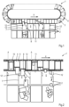
- Figs. 1 and 2 illustrate the functioning of the sorting device 1.
- Each of the figures shows successive travelling steps of the conveyor 3 in a single drawing.
- the figures illustrate two different situations at two different receiving units 2.
- the pushing element 10 of the carrier 4 is activated at the same location A upstream of the respective upstream edges 7 of the inlets 6 corresponding to the selected receiving units 2 where the discharged products should arrive.
- the product leaves the carrier 4 earlier and moves faster towards the destined inlet 6 than in the right situation.
- the left situation is indicated by imaginary path B of the product and the right situation is indicated by imaginary path C of the product. Since products that follow the imaginary path C also arrive in the intended receiving unit 2, the length of the inlet 6 in the direction of conveyance X can be relatively short.
- the left situation in Fig. 2 shows products of similar sizes and shapes and the right situation shows products of similar sizes and shapes, but in practice it may be a mixture of all kinds of products.
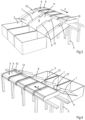
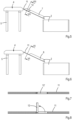
- the plate 12 which is located at the downstream edge 8 of the destined inlet 6 stands upright and forms an obstacle to the approaching product and forces the product to enter the destined inlet 6.
- This first position of the plates 12 is illustrated in Figs. 5 and 8 , for example. After guiding the product to the destined inlet 6 the plate 12 can be returned to its second position.
- Figs. 1-4 show that in the first position the plate 12 is aligned with the corresponding downstream edge 8, and in this case also with upstream edge 7 since the upstream edge 7 and the downstream edge 8 of two adjacent inlets 6 coincide.
- the discharging system may be adapted such that under operating conditions the movement of the plate 12, 12' from the second to the first position is synchronized with the start of moving the pushing element 10 of the carrier 4 which supports the product to be delivered at the inlet 6 at which downstream edge 8 the plate 12, 12' is located.
- the discharging system may be adapted such that under operating conditions the movement of the plate 12, 12' from the first to the second position is synchronized with the start of moving the pushing element 10 of the carrier 4 from which the product has been delivered at the inlet 6 at which downstream edge 8 the plate 12, 12' is located back to its initial position, but the movement of the plate 12, 12' from the first to the second position may be faster, for example directly after detecting that the product has entered the inlet 6 of the selected receiving unit.
- each of the carriers may comprise a tray which is tiltable about an axis which extends in the direction of conveyance by the discharging mechanism for discharging a product from the tray, or each of the carriers may comprise a cross-belt for supporting a product, which cross-belt is drivable by the discharging mechanism.
- the location of a product in transverse direction of the direction of conveyance X may have a greater effect on the location along the track where the product leaves the carrier after starting a discharging action at the same location along the track of the conveyor.
- the discharging system may comprise a guiding system which can selectively open and close the trays 13 of a carrier 4 when it passes one of the locations A, i.e. when the carrier 4 approaches the inlet 6 of the selected receiving unit 2, where the product on the carrier 4 should arrive.
- a guiding system which can selectively open and close the trays 13 of a carrier 4 when it passes one of the locations A, i.e. when the carrier 4 approaches the inlet 6 of the selected receiving unit 2, where the product on the carrier 4 should arrive.
- Such a conveyor is typically applied in well-known bombay sorters.
- the discharging system may be adapted such that under operating conditions the movement of the swing member 14, 14' from the second to the first position is synchronized with the start of opening the trays 13 of the carrier 4 which supports the product to be delivered at the inlet 6 at which upstream edge 7 the swing member 14, 14' is located.
- the discharging system may be adapted such that under operating conditions the movement of the swing member 14, 14' from the first to the second position is synchronized with the start of closing the trays 13 of the carrier 4 from which the product has been delivered at the inlet 6 at which upstream edge 7 the swing member 14, 14' is located.
- the invention provides the opportunity to have relatively short inlets in the direction of conveyance.
Landscapes
- Engineering & Computer Science (AREA)
- Mechanical Engineering (AREA)
- Discharge Of Articles From Conveyors (AREA)
- Branching, Merging, And Special Transfer Between Conveyors (AREA)
Priority Applications (9)
| Application Number | Priority Date | Filing Date | Title |
|---|---|---|---|
| RS20250575A RS66899B1 (sr) | 2021-02-11 | 2021-02-11 | Uređaj za sortiranje |
| PL21156589.0T PL4043372T3 (pl) | 2021-02-11 | 2021-02-11 | Urządzenie sortujące |
| HUE21156589A HUE071822T2 (hu) | 2021-02-11 | 2021-02-11 | Válogató berendezés |
| EP21156589.0A EP4043372B1 (en) | 2021-02-11 | 2021-02-11 | A sorting device |
| ES21156589T ES3029809T3 (en) | 2021-02-11 | 2021-02-11 | A sorting device |
| PCT/EP2022/052959 WO2022171599A1 (en) | 2021-02-11 | 2022-02-08 | A sorting device |
| US18/260,205 US12466668B2 (en) | 2021-02-11 | 2022-02-08 | Sorting device |
| CN202280014142.6A CN116867720B (zh) | 2021-02-11 | 2022-02-08 | 分拣装置 |
| JP2023548569A JP2024506096A (ja) | 2021-02-11 | 2022-02-08 | 仕分け装置 |
Applications Claiming Priority (1)
| Application Number | Priority Date | Filing Date | Title |
|---|---|---|---|
| EP21156589.0A EP4043372B1 (en) | 2021-02-11 | 2021-02-11 | A sorting device |
Publications (3)
| Publication Number | Publication Date |
|---|---|
| EP4043372A1 EP4043372A1 (en) | 2022-08-17 |
| EP4043372B1 true EP4043372B1 (en) | 2025-04-09 |
| EP4043372C0 EP4043372C0 (en) | 2025-04-09 |
Family
ID=74591874
Family Applications (1)
| Application Number | Title | Priority Date | Filing Date |
|---|---|---|---|
| EP21156589.0A Active EP4043372B1 (en) | 2021-02-11 | 2021-02-11 | A sorting device |
Country Status (9)
| Country | Link |
|---|---|
| US (1) | US12466668B2 (sr) |
| EP (1) | EP4043372B1 (sr) |
| JP (1) | JP2024506096A (sr) |
| CN (1) | CN116867720B (sr) |
| ES (1) | ES3029809T3 (sr) |
| HU (1) | HUE071822T2 (sr) |
| PL (1) | PL4043372T3 (sr) |
| RS (1) | RS66899B1 (sr) |
| WO (1) | WO2022171599A1 (sr) |
Families Citing this family (2)
| Publication number | Priority date | Publication date | Assignee | Title |
|---|---|---|---|---|
| DE102022205209A1 (de) * | 2022-05-24 | 2023-11-30 | Dürkopp Fördertechnik GmbH | Fördervorrichtung und Förderverfahren für Waren |
| DE102022205210A1 (de) * | 2022-05-24 | 2023-11-30 | Dürkopp Fördertechnik GmbH | Förderverfahren und Fördervorrichtung für Waren mehrerer Aufträge |
Family Cites Families (30)
| Publication number | Priority date | Publication date | Assignee | Title |
|---|---|---|---|---|
| JPS61171726U (sr) * | 1985-04-12 | 1986-10-24 | ||
| JPH0644898Y2 (ja) * | 1987-07-13 | 1994-11-16 | ト−ヨ−カネツ株式会社 | 仕分けシュ−ト |
| US5664660A (en) * | 1989-02-24 | 1997-09-09 | Kosan Crisplant A/S | Sorter conveyor |
| US5672039A (en) * | 1994-03-04 | 1997-09-30 | Computer Aided Systems, Inc. | Order consolidation indexing system |
| JPH08198436A (ja) * | 1994-11-21 | 1996-08-06 | Toyo Kanetsu Kk | マトリクス型仕分装置 |
| DE19721850C2 (de) * | 1996-11-05 | 2002-02-28 | Beumer Maschf Bernhard | Kipp-Förderelement für einen Sortierförderer |
| US6015039A (en) * | 1997-02-04 | 2000-01-18 | United Parcel Service Of America, Inc. | High speed tilted belt sorter |
| DE1016601T1 (de) * | 1998-05-21 | 2002-02-07 | Jaime Marti Sala | Bohrmeissel zum beaufschlagen einer formation |
| US6564922B1 (en) * | 2001-03-21 | 2003-05-20 | Lockheed Martin Corporation | Flex diverter |
| US6762382B1 (en) * | 2001-10-02 | 2004-07-13 | Innovative Picking Technologies, Inc. | Track-type sortation system |
| BR0215866A (pt) * | 2002-10-03 | 2005-09-27 | Alex Marti Mercade | Máquina de posicionamento e alinhamento de artigos que utiliza calhas de escoamento compreendidas por compartimentos múltiplos |
| JP4570415B2 (ja) * | 2003-07-30 | 2010-10-27 | 富山化学工業株式会社 | コンベヤ装置用の整列方法及び整列装置 |
| JP2005272118A (ja) * | 2004-03-26 | 2005-10-06 | Daiichi Kinzoku Kk | プレス製品分離機 |
| ES2250013B1 (es) * | 2005-09-09 | 2006-12-01 | Jaime Marti Sala | Maquina para orientar y alinear articulos. |
| NL1033313C2 (nl) * | 2007-01-31 | 2008-08-01 | Vanderlande Ind Nederland | Sorteerinrichting met name voor bagagestukken. |
| NL2000801C2 (nl) * | 2007-08-10 | 2009-02-11 | Eurosort B V | Sorteerinrichting. |
| NL1034940C2 (nl) * | 2008-01-22 | 2009-07-23 | Vanderlande Ind Nederland | Sorteerinrichting. |
| IT1396893B1 (it) * | 2009-11-12 | 2012-12-20 | Lorenzo Forni | Macchina riordinatrice per contenitori e relativo procedimento. |
| CN104411603B (zh) * | 2012-07-11 | 2016-10-26 | 德马泰克公司 | 交叉带分拣机系统和物品分拣方法 |
| US9795995B2 (en) * | 2015-05-06 | 2017-10-24 | Intelligrated Headquarters, Llc | High-speed, dual-sided shoe sorter with offset induct |
| US20160185533A1 (en) * | 2013-08-08 | 2016-06-30 | Crisplant A/S | Operating a sorting system for items having variating size |
| CN205294169U (zh) * | 2015-12-28 | 2016-06-08 | 沈志伟 | 带有卸载档口输送线的自动分拣装置 |
| DE102016109313A1 (de) * | 2016-05-20 | 2017-11-23 | Deutsche Post Ag | Rutsche für Stückgut und Verfahren zur Verwendung einer solchen Rutsche |
| US10059522B2 (en) * | 2016-11-04 | 2018-08-28 | Laitram, L.L.C. | Divert chutes in sorting-conveyor systems |
| US11080496B2 (en) * | 2017-04-18 | 2021-08-03 | Berkshire Grey, Inc. | Systems and methods for separating objects using vacuum diverts with one or more object processing systems |
| CN107983660B (zh) * | 2017-12-27 | 2022-12-09 | 福建星云电子股份有限公司 | 一种分选机的分选导向装置及系统 |
| NL2020334B1 (en) * | 2018-01-26 | 2019-07-31 | Optimus Sorter Holding B V | Sorting device with improved capacity |
| US10668506B2 (en) * | 2018-04-24 | 2020-06-02 | Beumer Group Gmbh & Co. Kg. | Sorting conveyor with article removal device |
| CN109719040B (zh) * | 2018-05-15 | 2021-12-21 | 珠海星植流电机有限公司 | 一种立体结构式包裹分拣装置 |
| US11111084B1 (en) * | 2019-12-04 | 2021-09-07 | Amazon Technologies, Inc. | Automatic tray dispensing |
-
2021
- 2021-02-11 EP EP21156589.0A patent/EP4043372B1/en active Active
- 2021-02-11 PL PL21156589.0T patent/PL4043372T3/pl unknown
- 2021-02-11 HU HUE21156589A patent/HUE071822T2/hu unknown
- 2021-02-11 RS RS20250575A patent/RS66899B1/sr unknown
- 2021-02-11 ES ES21156589T patent/ES3029809T3/es active Active
-
2022
- 2022-02-08 JP JP2023548569A patent/JP2024506096A/ja active Pending
- 2022-02-08 US US18/260,205 patent/US12466668B2/en active Active
- 2022-02-08 CN CN202280014142.6A patent/CN116867720B/zh active Active
- 2022-02-08 WO PCT/EP2022/052959 patent/WO2022171599A1/en not_active Ceased
Also Published As
| Publication number | Publication date |
|---|---|
| JP2024506096A (ja) | 2024-02-08 |
| PL4043372T3 (pl) | 2025-08-18 |
| CN116867720A (zh) | 2023-10-10 |
| US12466668B2 (en) | 2025-11-11 |
| CN116867720B (zh) | 2026-03-27 |
| HUE071822T2 (hu) | 2025-09-28 |
| US20240067466A1 (en) | 2024-02-29 |
| EP4043372C0 (en) | 2025-04-09 |
| EP4043372A1 (en) | 2022-08-17 |
| WO2022171599A1 (en) | 2022-08-18 |
| RS66899B1 (sr) | 2025-07-31 |
| ES3029809T3 (en) | 2025-06-25 |
Similar Documents
| Publication | Publication Date | Title |
|---|---|---|
| JPH0858575A (ja) | 搬送設備 | |
| US5435429A (en) | Conveyor | |
| US4732260A (en) | Apparatus for the selection and sorting of objects | |
| EP0480436B1 (en) | Distributing and collecting device for products to be conveyed | |
| US4195737A (en) | Method and apparatus for handling elongated articles, such as pieces of timber | |
| CN103209913B (zh) | 用于转移物品的装置 | |
| JP2023529804A (ja) | バッファ仕分け | |
| US12466668B2 (en) | Sorting device | |
| US5392894A (en) | Transport/stacker module for improving sorting throughout of a mail processing system | |
| US5842556A (en) | Device for sorting goods | |
| JP3943174B2 (ja) | 上、下物品を同時に受承する排出ホッパ及び上、下物品を分類する方法 | |
| EP2298460B1 (en) | Transporter/sorter and transport box | |
| US5722532A (en) | Convergent/divergent product conveyor | |
| EP2197770B1 (en) | Sorting apparatus | |
| JPH05193732A (ja) | 卵のごとき物品の受容または転送、垂直搬送および供給装置 | |
| US3918572A (en) | Lateral discharge chute and gate apparatus | |
| EP3798161B1 (en) | An apparatus for transport and controlled discharge of products | |
| US3049218A (en) | Sorting system for post offices and the like | |
| JPH0644898Y2 (ja) | 仕分けシュ−ト | |
| US3325005A (en) | Tableware sorter | |
| NL2001708C2 (en) | A conveying device. | |
| US3991866A (en) | Discharge chute structure | |
| BE507878A (sr) | ||
| JPH03242791A (ja) | 自動販売機の商品搬出装置 |
Legal Events
| Date | Code | Title | Description |
|---|---|---|---|
| PUAI | Public reference made under article 153(3) epc to a published international application that has entered the european phase |
Free format text: ORIGINAL CODE: 0009012 |
|
| STAA | Information on the status of an ep patent application or granted ep patent |
Free format text: STATUS: THE APPLICATION HAS BEEN PUBLISHED |
|
| AK | Designated contracting states |
Kind code of ref document: A1 Designated state(s): AL AT BE BG CH CY CZ DE DK EE ES FI FR GB GR HR HU IE IS IT LI LT LU LV MC MK MT NL NO PL PT RO RS SE SI SK SM TR |
|
| STAA | Information on the status of an ep patent application or granted ep patent |
Free format text: STATUS: REQUEST FOR EXAMINATION WAS MADE |
|
| 17P | Request for examination filed |
Effective date: 20230208 |
|
| RBV | Designated contracting states (corrected) |
Designated state(s): AL AT BE BG CH CY CZ DE DK EE ES FI FR GB GR HR HU IE IS IT LI LT LU LV MC MK MT NL NO PL PT RO RS SE SI SK SM TR |
|
| GRAP | Despatch of communication of intention to grant a patent |
Free format text: ORIGINAL CODE: EPIDOSNIGR1 |
|
| STAA | Information on the status of an ep patent application or granted ep patent |
Free format text: STATUS: GRANT OF PATENT IS INTENDED |
|
| INTG | Intention to grant announced |
Effective date: 20241030 |
|
| GRAS | Grant fee paid |
Free format text: ORIGINAL CODE: EPIDOSNIGR3 |
|
| GRAA | (expected) grant |
Free format text: ORIGINAL CODE: 0009210 |
|
| STAA | Information on the status of an ep patent application or granted ep patent |
Free format text: STATUS: THE PATENT HAS BEEN GRANTED |
|
| AK | Designated contracting states |
Kind code of ref document: B1 Designated state(s): AL AT BE BG CH CY CZ DE DK EE ES FI FR GB GR HR HU IE IS IT LI LT LU LV MC MK MT NL NO PL PT RO RS SE SI SK SM TR |
|
| REG | Reference to a national code |
Ref country code: GB Ref legal event code: FG4D |
|
| REG | Reference to a national code |
Ref country code: CH Ref legal event code: EP |
|
| REG | Reference to a national code |
Ref country code: DE Ref legal event code: R096 Ref document number: 602021028741 Country of ref document: DE |
|
| REG | Reference to a national code |
Ref country code: IE Ref legal event code: FG4D |
|
| U01 | Request for unitary effect filed |
Effective date: 20250502 |
|
| U07 | Unitary effect registered |
Designated state(s): AT BE BG DE DK EE FI FR IT LT LU LV MT NL PT RO SE SI Effective date: 20250509 |
|
| REG | Reference to a national code |
Ref country code: ES Ref legal event code: FG2A Ref document number: 3029809 Country of ref document: ES Kind code of ref document: T3 Effective date: 20250625 |
|
| REG | Reference to a national code |
Ref country code: GR Ref legal event code: EP Ref document number: 20250401276 Country of ref document: GR Effective date: 20250707 |
|
| REG | Reference to a national code |
Ref country code: HU Ref legal event code: AG4A Ref document number: E071822 Country of ref document: HU |
|
| PG25 | Lapsed in a contracting state [announced via postgrant information from national office to epo] |
Ref country code: NO Free format text: LAPSE BECAUSE OF FAILURE TO SUBMIT A TRANSLATION OF THE DESCRIPTION OR TO PAY THE FEE WITHIN THE PRESCRIBED TIME-LIMIT Effective date: 20250709 |
|
| PG25 | Lapsed in a contracting state [announced via postgrant information from national office to epo] |
Ref country code: HR Free format text: LAPSE BECAUSE OF FAILURE TO SUBMIT A TRANSLATION OF THE DESCRIPTION OR TO PAY THE FEE WITHIN THE PRESCRIBED TIME-LIMIT Effective date: 20250409 |
|
| PG25 | Lapsed in a contracting state [announced via postgrant information from national office to epo] |
Ref country code: IS Free format text: LAPSE BECAUSE OF FAILURE TO SUBMIT A TRANSLATION OF THE DESCRIPTION OR TO PAY THE FEE WITHIN THE PRESCRIBED TIME-LIMIT Effective date: 20250809 |
|
| PG25 | Lapsed in a contracting state [announced via postgrant information from national office to epo] |
Ref country code: SM Free format text: LAPSE BECAUSE OF FAILURE TO SUBMIT A TRANSLATION OF THE DESCRIPTION OR TO PAY THE FEE WITHIN THE PRESCRIBED TIME-LIMIT Effective date: 20250409 |
|
| PG25 | Lapsed in a contracting state [announced via postgrant information from national office to epo] |
Ref country code: CZ Free format text: LAPSE BECAUSE OF FAILURE TO SUBMIT A TRANSLATION OF THE DESCRIPTION OR TO PAY THE FEE WITHIN THE PRESCRIBED TIME-LIMIT Effective date: 20250409 |
|
| PG25 | Lapsed in a contracting state [announced via postgrant information from national office to epo] |
Ref country code: SK Free format text: LAPSE BECAUSE OF FAILURE TO SUBMIT A TRANSLATION OF THE DESCRIPTION OR TO PAY THE FEE WITHIN THE PRESCRIBED TIME-LIMIT Effective date: 20250409 |
|
| PLBE | No opposition filed within time limit |
Free format text: ORIGINAL CODE: 0009261 |
|
| STAA | Information on the status of an ep patent application or granted ep patent |
Free format text: STATUS: NO OPPOSITION FILED WITHIN TIME LIMIT |
|
| REG | Reference to a national code |
Ref country code: CH Ref legal event code: L10 Free format text: ST27 STATUS EVENT CODE: U-0-0-L10-L00 (AS PROVIDED BY THE NATIONAL OFFICE) Effective date: 20260218 |
|
| 26N | No opposition filed |
Effective date: 20260112 |
|
| PGFP | Annual fee paid to national office [announced via postgrant information from national office to epo] |
Ref country code: HU Payment date: 20260127 Year of fee payment: 6 |
|
| U20 | Renewal fee for the european patent with unitary effect paid |
Year of fee payment: 6 Effective date: 20260227 |
|
| PGFP | Annual fee paid to national office [announced via postgrant information from national office to epo] |
Ref country code: GB Payment date: 20260227 Year of fee payment: 6 |
|
| PGFP | Annual fee paid to national office [announced via postgrant information from national office to epo] |
Ref country code: ES Payment date: 20260302 Year of fee payment: 6 |
|
| PGFP | Annual fee paid to national office [announced via postgrant information from national office to epo] |
Ref country code: RS Payment date: 20260121 Year of fee payment: 6 |
|
| PGFP | Annual fee paid to national office [announced via postgrant information from national office to epo] |
Ref country code: GR Payment date: 20260226 Year of fee payment: 6 Ref country code: PL Payment date: 20260122 Year of fee payment: 6 |