EP4042004B1 - Moteur à combustion interne doté de carter de cylindre et de culasse de cylindre à fixation de ventilateur réglable en hauteur intégrée pour des courroies à nervures en v élastiques - Google Patents
Moteur à combustion interne doté de carter de cylindre et de culasse de cylindre à fixation de ventilateur réglable en hauteur intégrée pour des courroies à nervures en v élastiques Download PDFInfo
- Publication number
- EP4042004B1 EP4042004B1 EP20793262.5A EP20793262A EP4042004B1 EP 4042004 B1 EP4042004 B1 EP 4042004B1 EP 20793262 A EP20793262 A EP 20793262A EP 4042004 B1 EP4042004 B1 EP 4042004B1
- Authority
- EP
- European Patent Office
- Prior art keywords
- fan
- internal combustion
- combustion engine
- cylinder head
- belt
- Prior art date
- Legal status (The legal status is an assumption and is not a legal conclusion. Google has not performed a legal analysis and makes no representation as to the accuracy of the status listed.)
- Active
Links
Images


Classifications
-
- F—MECHANICAL ENGINEERING; LIGHTING; HEATING; WEAPONS; BLASTING
- F02—COMBUSTION ENGINES; HOT-GAS OR COMBUSTION-PRODUCT ENGINE PLANTS
- F02B—INTERNAL-COMBUSTION PISTON ENGINES; COMBUSTION ENGINES IN GENERAL
- F02B67/00—Engines characterised by the arrangement of auxiliary apparatus not being otherwise provided for, e.g. the apparatus having different functions; Driving auxiliary apparatus from engines, not otherwise provided for
- F02B67/04—Engines characterised by the arrangement of auxiliary apparatus not being otherwise provided for, e.g. the apparatus having different functions; Driving auxiliary apparatus from engines, not otherwise provided for of mechanically-driven auxiliary apparatus
- F02B67/06—Engines characterised by the arrangement of auxiliary apparatus not being otherwise provided for, e.g. the apparatus having different functions; Driving auxiliary apparatus from engines, not otherwise provided for of mechanically-driven auxiliary apparatus driven by means of chains, belts, or like endless members
-
- F—MECHANICAL ENGINEERING; LIGHTING; HEATING; WEAPONS; BLASTING
- F01—MACHINES OR ENGINES IN GENERAL; ENGINE PLANTS IN GENERAL; STEAM ENGINES
- F01P—COOLING OF MACHINES OR ENGINES IN GENERAL; COOLING OF INTERNAL-COMBUSTION ENGINES
- F01P3/00—Liquid cooling
- F01P3/20—Cooling circuits not specific to a single part of engine or machine
-
- F—MECHANICAL ENGINEERING; LIGHTING; HEATING; WEAPONS; BLASTING
- F01—MACHINES OR ENGINES IN GENERAL; ENGINE PLANTS IN GENERAL; STEAM ENGINES
- F01P—COOLING OF MACHINES OR ENGINES IN GENERAL; COOLING OF INTERNAL-COMBUSTION ENGINES
- F01P5/00—Pumping cooling-air or liquid coolants
- F01P5/02—Pumping cooling-air; Arrangements of cooling-air pumps, e.g. fans or blowers
- F01P5/04—Pump-driving arrangements
-
- F—MECHANICAL ENGINEERING; LIGHTING; HEATING; WEAPONS; BLASTING
- F16—ENGINEERING ELEMENTS AND UNITS; GENERAL MEASURES FOR PRODUCING AND MAINTAINING EFFECTIVE FUNCTIONING OF MACHINES OR INSTALLATIONS; THERMAL INSULATION IN GENERAL
- F16H—GEARING
- F16H7/00—Gearings for conveying rotary motion by endless flexible members
- F16H7/08—Means for varying tension of belts, ropes or chains
- F16H7/10—Means for varying tension of belts, ropes or chains by adjusting the axis of a pulley
-
- F—MECHANICAL ENGINEERING; LIGHTING; HEATING; WEAPONS; BLASTING
- F02—COMBUSTION ENGINES; HOT-GAS OR COMBUSTION-PRODUCT ENGINE PLANTS
- F02B—INTERNAL-COMBUSTION PISTON ENGINES; COMBUSTION ENGINES IN GENERAL
- F02B75/00—Other engines
- F02B75/007—Other engines having vertical crankshafts
Definitions
- the invention relates to an internal combustion engine with a cylinder crankcase and a cylinder head with integrated height-adjustable fan attachment for elastic V-ribbed belts.
- Such internal combustion engines are known, for example, from the JP-A2008-31937 or the Japanese unexamined patent publication JPA2001-220771 .
- JP-A2001-220771 discloses an invention in which, on a top surface of an engine, an alternator and a compressor are arranged side by side in a shaft center direction of an output shaft of the engine, and also discloses an invention in which, on a top surface of an engine, an alternator and a compressor are arranged side by side in a horizontal direction perpendicular to a shaft center of the engine.
- an internal combustion engine with a fan attached to a pulley is known.
- the pulley is mounted on an axle that has an eccentric shoulder.
- a bracket is attached to the internal combustion engine and comprises an elongated hole and a fork-shaped element.
- the eccentric shoulder extends through the elongated hole and the fork-shaped element.
- An internal combustion engine with a fan is known.
- the internal combustion engine has a cover that is attached to a cylinder block.
- a bushing is integrated into the cover, in which a spring element is accommodated.
- the fan is spring-mounted on the spring element in order to maintain tension in the belt that drives the fan.
- the EN 23 18 104 discloses a fan drive in which the fan is driven by a V-belt drive and a slip clutch that is dependent on the engine speed, the driving part of the slip clutch being connected to the V-belt pulley in a rotationally fixed manner and the V-belt pulley and the driving part of the slip clutch being provided via a bearing so that they can rotate relatively and are coaxial with a shaft on which the driven part of the slip clutch and the fan are pivoted in a rotationally locked manner.
- the disadvantage of this is again the resulting additional bearing loads on the auxiliary units caused by the common shaft, even if this is speed-decoupled.
- a slip clutch is also required.
- a fan drive is proposed that can be driven by an internal combustion engine of a motor vehicle, by means of a fluid friction clutch and with means for increasing the fan speed.
- the fan is arranged coaxially to the crankshaft of the internal combustion engine.
- Auxiliary units are arranged parallel to the crankshaft. which can be driven by the combustion engine via a common first belt drive with a high-speed gear ratio.
- the fan can be driven directly from the crankshaft via a first drive train, into which the fluid friction clutch, consisting of drive shaft, drive pulley and housing, and a freewheel are connected, and alternatively - to increase the fan speed - via a second drive train, which includes a second belt drive from an auxiliary unit to the fluid friction clutch and can be switched on or off via a clutch.
- a first drive train into which the fluid friction clutch, consisting of drive shaft, drive pulley and housing, and a freewheel are connected
- a second drive train which includes a second belt drive from an auxiliary unit to the fluid friction clutch and can be switched on or off via a clutch.
- the length of the engine is particularly important in order to keep the devices in which this engine is to be installed compact.
- One criterion for the length of the engine is the cylinder crankcase and the cylinder head with their fan attachment.
- Known designs show height-adjustable fan brackets that are screwed in front of or onto the cylinder crankcase and/or in front of or onto the cylinder head.
- the brackets sometimes accommodate tensioning elements for the V-ribbed belt.
- tensioning elements for the V-ribbed belt are attached to the cylinder crankcase and/or the cylinder head.
- the fan attachments are attached to the fan brackets.
- the fan attachments accommodate the fan including the pulley and fan bearing. This requires a sufficiently large installation space.
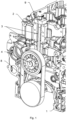
- FIG.1 and 2 an internal combustion engine with fan attachments such as fans, pulleys and fan bearings 5 is shown, which noticeably reduces the overall length of the engine. This is achieved by integrating the height-adjustable fan bracket 3 into the cylinder crankcase 1 and the cylinder head 2.
- the fan attachments including fans, pulleys and fan bearings 5 are then attached directly to the cylinder crankcase 1 and/or the cylinder head 2.
- the fan bearing 5 runs in two internal guide grooves in the manner of a T-slot nut or a T-slot stone 11 - also called a sliding stone - a threaded hole or, in this case, four threaded holes are arranged in the fan bearing 5 to accommodate the screws 10.
- a stone like this is used, for example, to connect the machine table and the workpiece in a machine tool. It is axially movable in a T-slot of the table or, here, in the guide groove 6, which is arranged in the cylinder crankcase 1 and/or the cylinder head 2. It creates a screwing point for the workpiece using a special screw and can be adjusted in height within a given hole pitch 7.
- the pre-tension of an elastic V-ribbed belt 8 is achieved by screwing the fan attachments including fan, pulleys and The fan bearing 5 is brought into the desired position using an assembly/clamping tool 9 and then screwed to the cylinder crankcase 1 and/or the cylinder head 2 using screws 10.
- the assembly/clamping tool 9 which consists of an abutment that can be screwed to the cylinder head 2 above the guide groove 6 and that has a guide hole for receiving a rack that is screwed into a thread in the sliding block 11, is arranged so as to be removable. A nut is arranged on the rack on the abutment, by means of which the rack can adjust the height of the fan bearing 5. The assembly/clamping tool 9 can be removed after the fan bearing 5 has been fixed in its working position using the screws 10.
- the four through holes for receiving the screws 10 on the sliding block 11 have threads, so that the sliding block 11 is clamped against the guide grooves 6 by means of the screws 10, so that the fan bearing 5 can be arranged at a variable height.
- Fig.3 the internal combustion engine is switched off Fig.1 and 2 with the fan bearing 5 removed.
- the back of the fan bearing 5 is designed like a sliding block 11.
- the fan bearing is guided in the guide grooves 6 of the cylinder head 2 and the cylinder crankcase 1 and is fixed in the working position with the screws 10 in the threads of the hole 7.
- Fig.4 shows a plan view of the front side of the internal combustion engine with the fan bearing 5.
- the arrangement of the sliding block 11 of the fan bearing 5 in the guide grooves 6, which are machined in the cylinder head 2 and the cylinder crankcase 1, can be seen.
Landscapes
- Engineering & Computer Science (AREA)
- General Engineering & Computer Science (AREA)
- Mechanical Engineering (AREA)
- Chemical & Material Sciences (AREA)
- Combustion & Propulsion (AREA)
- Devices For Conveying Motion By Means Of Endless Flexible Members (AREA)
Claims (6)
- Moteur à combustion interne, comprenant :un carter-cylindres (1) ;une culasse (2)au moins un dispositif d'entraînement d'un ventilateur, notamment d'un véhicule, en particulier d'un véhicule utilitaire, par lequel le ventilateur est disposé de manière à pouvoir être déplacé par rapport à un vilebrequin du moteur à combustion interne,dans lequel le dispositif d'entraînement d'un ventilateur comprend un support de ventilateur (3) et un palier de ventilateur (5) ; etune transmission par courroie, par laquelle le ventilateur peut être entraîné, dans laquelle la transmission par courroie présente une première poulie et une deuxième poulie reliées par une courroie (8) en liaison d'entraînement, et la première poulie étant disposée sur le palier de ventilateur (5),caractérisé en ce que le palier de ventilateur (5) est configuré comme un bloc de rainure en T, qui est situé de manière à pouvoir coulisser axialement dans une rainure de guidage (6), qui est disposée dans le carter-cylindres (1) et/ou la culasse (2).
- Moteur à combustion interne selon la revendication 1,
caractérisé en ce que la courroie (8) est une courroie à nervure en V. - Moteur à combustion interne selon l'une ou plusieurs des revendications précédentes,
caractérisé en ce que le support de ventilateur (3) présente une perforation. - Moteur à combustion interne selon l'une ou plusieurs des revendications précédentes,
caractérisé en ce que le support de ventilateur (3) présente un outil de montage et de serrage (9). - Moteur à combustion interne selon la revendication 4,
caractérisé en ce que l'outil de montage et de serrage (9) est conçu de manière amovible. - Procédé de fonctionnement d'un moteur à combustion interne,
caractérisé en ce qu'un moteur à combustion interne selon l'une ou plusieurs des revendications précédentes est utilisé.
Applications Claiming Priority (2)
| Application Number | Priority Date | Filing Date | Title |
|---|---|---|---|
| DE102019007007.0A DE102019007007A1 (de) | 2019-10-09 | 2019-10-09 | Brennkraftmaschine mit einem Zylinderkurbelgehäuse und einem Zylinderkopf mit integriertem höhenverstellbarem Lüfteranbau für elastische Keilrippenriemen |
| PCT/EP2020/000170 WO2021069089A1 (fr) | 2019-10-09 | 2020-10-05 | Moteur à combustion interne doté de carter de cylindre et de culasse de cylindre à fixation de ventilateur réglable en hauteur intégrée pour des courroies à nervures en v élastiques |
Publications (2)
| Publication Number | Publication Date |
|---|---|
| EP4042004A1 EP4042004A1 (fr) | 2022-08-17 |
| EP4042004B1 true EP4042004B1 (fr) | 2024-09-11 |
Family
ID=72944091
Family Applications (1)
| Application Number | Title | Priority Date | Filing Date |
|---|---|---|---|
| EP20793262.5A Active EP4042004B1 (fr) | 2019-10-09 | 2020-10-05 | Moteur à combustion interne doté de carter de cylindre et de culasse de cylindre à fixation de ventilateur réglable en hauteur intégrée pour des courroies à nervures en v élastiques |
Country Status (6)
| Country | Link |
|---|---|
| US (1) | US12085013B2 (fr) |
| EP (1) | EP4042004B1 (fr) |
| JP (1) | JP7564518B2 (fr) |
| CN (1) | CN114423936B (fr) |
| DE (1) | DE102019007007A1 (fr) |
| WO (1) | WO2021069089A1 (fr) |
Families Citing this family (1)
| Publication number | Priority date | Publication date | Assignee | Title |
|---|---|---|---|---|
| US20240068488A1 (en) * | 2022-08-30 | 2024-02-29 | Lombardini S.R.L. | Universal fan shaft mounting plate |
Family Cites Families (21)
| Publication number | Priority date | Publication date | Assignee | Title |
|---|---|---|---|---|
| US1002848A (en) * | 1908-06-27 | 1911-09-12 | Packard Motor Car Co | Motor-vehicle. |
| US1639449A (en) * | 1921-11-12 | 1927-08-16 | Int Harvester Co | Internal-combustion engine |
| US1530299A (en) * | 1923-07-24 | 1925-03-17 | Chilcott Thomas Robert Relleen | Circulating oil pump for internal-combustion engines |
| US2526242A (en) * | 1945-06-04 | 1950-10-17 | Hercules Motors Corp | Fan drive |
| US3362243A (en) * | 1967-02-14 | 1968-01-09 | Hunt Foods And Ind Inc | Engine cooling fan assembly |
| US3603296A (en) * | 1970-04-02 | 1971-09-07 | Gen Motors Corp | Engine camshaft and accessory drive |
| DE2318104A1 (de) | 1973-04-11 | 1974-10-24 | Luk Lamellen & Kupplungsbau | Luefterantrieb |
| JPS60121549U (ja) * | 1984-01-24 | 1985-08-16 | トヨタ自動車株式会社 | Vリブドベルトを用いた動力伝達機構 |
| DE4216135A1 (de) * | 1991-05-16 | 1992-11-19 | Mazda Motor | Steuervorrichtung fuer einen rotationskoerper zum kuehlen eines motors |
| JP3520115B2 (ja) * | 1994-07-30 | 2004-04-19 | スズキ株式会社 | ファン取付構造 |
| DE19725216C1 (de) | 1997-06-15 | 1998-11-19 | Daimler Benz Ag | Vorrichtung zum Antreiben von Aggregaten einer Brennkraftmaschine |
| JP2001220771A (ja) | 2000-02-10 | 2001-08-17 | Komatsu Engineering Kk | 建設車輌 |
| DE10324314B4 (de) | 2002-06-12 | 2014-02-13 | Behr Gmbh & Co. Kg | Lüfterantrieb für Kraftfahrzeuge |
| DE10317507A1 (de) * | 2003-04-16 | 2004-11-04 | Daimlerchrysler Ag | Antriebsvorrichtung für einen Kühllüfter eines Kraftfahrzeugs |
| CN2744842Y (zh) * | 2004-08-19 | 2005-12-07 | 安徽合力股份有限公司 | 内燃发动机自带直拖泵装置 |
| JP2008031937A (ja) | 2006-07-28 | 2008-02-14 | Yanmar Co Ltd | 補機駆動装置 |
| CN203769913U (zh) * | 2014-03-05 | 2014-08-13 | 广西玉柴机器股份有限公司 | 一种发动机风扇布置的安装结构 |
| DE102015008721A1 (de) * | 2015-07-04 | 2017-01-05 | Man Truck & Bus Ag | Lüfterantrieb für ein Kraftfahrzeug |
| CN205779251U (zh) | 2016-06-07 | 2016-12-07 | 潍柴动力股份有限公司 | 风扇高度可调的发动机前端轮系 |
| DE102016015152A1 (de) * | 2016-12-20 | 2018-06-21 | Daimler Ag | Lüfteranordnung für eine Verbrennungskraftmaschine |
| CN207776980U (zh) * | 2018-01-24 | 2018-08-28 | 中国重汽集团济南动力有限公司 | 一种新型低位风扇托架总成 |
-
2019
- 2019-10-09 DE DE102019007007.0A patent/DE102019007007A1/de not_active Ceased
-
2020
- 2020-10-05 US US17/767,571 patent/US12085013B2/en active Active
- 2020-10-05 EP EP20793262.5A patent/EP4042004B1/fr active Active
- 2020-10-05 WO PCT/EP2020/000170 patent/WO2021069089A1/fr not_active Ceased
- 2020-10-05 JP JP2022508576A patent/JP7564518B2/ja active Active
- 2020-10-05 CN CN202080065225.9A patent/CN114423936B/zh active Active
Also Published As
| Publication number | Publication date |
|---|---|
| JP2022550931A (ja) | 2022-12-06 |
| EP4042004A1 (fr) | 2022-08-17 |
| DE102019007007A1 (de) | 2021-04-15 |
| CN114423936A (zh) | 2022-04-29 |
| WO2021069089A1 (fr) | 2021-04-15 |
| US20240084729A1 (en) | 2024-03-14 |
| JP7564518B2 (ja) | 2024-10-09 |
| US12085013B2 (en) | 2024-09-10 |
| CN114423936B (zh) | 2024-08-23 |
Similar Documents
| Publication | Publication Date | Title |
|---|---|---|
| DE19807822B4 (de) | Schwenklager | |
| EP1875105B1 (fr) | Entrainement a element de traction, notamment entrainement a courroie pour des groupes auxiliaires d'un moteur a combustion interne | |
| DE69301050T2 (de) | Exzentrische Kurbelwelle für einen Luftverdichter mit Verdrängerkolben | |
| EP4042004B1 (fr) | Moteur à combustion interne doté de carter de cylindre et de culasse de cylindre à fixation de ventilateur réglable en hauteur intégrée pour des courroies à nervures en v élastiques | |
| DE102017117352A1 (de) | Aussenfeder zum erhöhen der spannung an einem riemenspanner für einen verbrennungsmotor | |
| DE4202001A1 (de) | Riemenantrieb von elektrischen maschinen | |
| EP1607657A2 (fr) | Tendeur de courroie et transmission à courroie comprenant un tel tendeur de courroie | |
| DE69936522T2 (de) | Steifer kurbelwellenhalter und betätigungsvorrichtung | |
| EP1913286B1 (fr) | Entrainement par courroie | |
| EP3115242B1 (fr) | Entraînement hybride pour un vehicule automobile | |
| DE3724409A1 (de) | Kraftstoffeinspritzpumpe fuer brennkraftmaschinen | |
| DE112015001284B4 (de) | Anbringungsstruktur für ein Kraftmaschinenzubehör | |
| DE3819030A1 (de) | Oelpumpenanordnung fuer den druckschmieroelkreislauf einer mit unterschiedlichen drehzahlen arbeitenden maschine | |
| DE102006033270B4 (de) | Hubkolben-Brennkraftmaschine | |
| DE102011085594A1 (de) | Spannvorrichtung für einen Zugmitteltrieb einer Brennkraftmaschine | |
| DE102018109539B3 (de) | Pendelspanner mit Federfußpunktverschiebung mittels Keilprinzip, Endloszugmitteltrieb und Einstellverfahren zum Einstellen der Spannkraft eines Pendelspanners | |
| DE102008060931A1 (de) | Getriebegehäuse für eine Stellvorrichtung | |
| DE3626530C1 (de) | Anordnung eines Aggregates mittels der Verschraubung eines hochbelasteten Maschinenteils,insbesondere bei Brennkraftmaschinen | |
| EP3748193A2 (fr) | Agencement de serrage pourvu de rouleau de serrage et dispositif de réglage d'un agencement de serrage | |
| WO2020078796A1 (fr) | Liaison moyeu-moyeu pour un groupe électrogène | |
| DE102005003552B4 (de) | Kreuzkopfmotor | |
| DE102005031295B4 (de) | Antriebseinrichtung mit zwei an der Stirnseite eines Verbrennungsmotors angeordneten Riementrieben | |
| DE473677C (de) | Vorrichtung fuer Brennkraftmaschinen mit veraenderlichem Verdichtungsraum, insbesondere fuer Versuche mit Luftfahrzeugmotoren | |
| AT521164B1 (de) | Verbrennungskraftmaschine | |
| EP3772593B1 (fr) | Outil de travail motorisé avec carter de ventilateur de refroidissement renforcé |
Legal Events
| Date | Code | Title | Description |
|---|---|---|---|
| STAA | Information on the status of an ep patent application or granted ep patent |
Free format text: STATUS: UNKNOWN |
|
| STAA | Information on the status of an ep patent application or granted ep patent |
Free format text: STATUS: THE INTERNATIONAL PUBLICATION HAS BEEN MADE |
|
| PUAI | Public reference made under article 153(3) epc to a published international application that has entered the european phase |
Free format text: ORIGINAL CODE: 0009012 |
|
| STAA | Information on the status of an ep patent application or granted ep patent |
Free format text: STATUS: REQUEST FOR EXAMINATION WAS MADE |
|
| 17P | Request for examination filed |
Effective date: 20220325 |
|
| AK | Designated contracting states |
Kind code of ref document: A1 Designated state(s): AL AT BE BG CH CY CZ DE DK EE ES FI FR GB GR HR HU IE IS IT LI LT LU LV MC MK MT NL NO PL PT RO RS SE SI SK SM TR |
|
| DAV | Request for validation of the european patent (deleted) | ||
| DAX | Request for extension of the european patent (deleted) | ||
| STAA | Information on the status of an ep patent application or granted ep patent |
Free format text: STATUS: EXAMINATION IS IN PROGRESS |
|
| 17Q | First examination report despatched |
Effective date: 20230220 |
|
| GRAP | Despatch of communication of intention to grant a patent |
Free format text: ORIGINAL CODE: EPIDOSNIGR1 |
|
| STAA | Information on the status of an ep patent application or granted ep patent |
Free format text: STATUS: GRANT OF PATENT IS INTENDED |
|
| INTG | Intention to grant announced |
Effective date: 20240528 |
|
| GRAS | Grant fee paid |
Free format text: ORIGINAL CODE: EPIDOSNIGR3 |
|
| GRAA | (expected) grant |
Free format text: ORIGINAL CODE: 0009210 |
|
| STAA | Information on the status of an ep patent application or granted ep patent |
Free format text: STATUS: THE PATENT HAS BEEN GRANTED |
|
| AK | Designated contracting states |
Kind code of ref document: B1 Designated state(s): AL AT BE BG CH CY CZ DE DK EE ES FI FR GB GR HR HU IE IS IT LI LT LU LV MC MK MT NL NO PL PT RO RS SE SI SK SM TR |
|
| REG | Reference to a national code |
Ref country code: GB Ref legal event code: FG4D Free format text: NOT ENGLISH |
|
| REG | Reference to a national code |
Ref country code: CH Ref legal event code: EP |
|
| REG | Reference to a national code |
Ref country code: DE Ref legal event code: R096 Ref document number: 502020009223 Country of ref document: DE |
|
| REG | Reference to a national code |
Ref country code: IE Ref legal event code: FG4D Free format text: LANGUAGE OF EP DOCUMENT: GERMAN |
|
| REG | Reference to a national code |
Ref country code: LT Ref legal event code: MG9D |
|
| PG25 | Lapsed in a contracting state [announced via postgrant information from national office to epo] |
Ref country code: NO Free format text: LAPSE BECAUSE OF FAILURE TO SUBMIT A TRANSLATION OF THE DESCRIPTION OR TO PAY THE FEE WITHIN THE PRESCRIBED TIME-LIMIT Effective date: 20241211 |
|
| REG | Reference to a national code |
Ref country code: NL Ref legal event code: MP Effective date: 20240911 |
|
| PG25 | Lapsed in a contracting state [announced via postgrant information from national office to epo] |
Ref country code: GR Free format text: LAPSE BECAUSE OF FAILURE TO SUBMIT A TRANSLATION OF THE DESCRIPTION OR TO PAY THE FEE WITHIN THE PRESCRIBED TIME-LIMIT Effective date: 20241212 Ref country code: FI Free format text: LAPSE BECAUSE OF FAILURE TO SUBMIT A TRANSLATION OF THE DESCRIPTION OR TO PAY THE FEE WITHIN THE PRESCRIBED TIME-LIMIT Effective date: 20240911 |
|
| PG25 | Lapsed in a contracting state [announced via postgrant information from national office to epo] |
Ref country code: BG Free format text: LAPSE BECAUSE OF FAILURE TO SUBMIT A TRANSLATION OF THE DESCRIPTION OR TO PAY THE FEE WITHIN THE PRESCRIBED TIME-LIMIT Effective date: 20240911 |
|
| PG25 | Lapsed in a contracting state [announced via postgrant information from national office to epo] |
Ref country code: LV Free format text: LAPSE BECAUSE OF FAILURE TO SUBMIT A TRANSLATION OF THE DESCRIPTION OR TO PAY THE FEE WITHIN THE PRESCRIBED TIME-LIMIT Effective date: 20240911 |
|
| PG25 | Lapsed in a contracting state [announced via postgrant information from national office to epo] |
Ref country code: HR Free format text: LAPSE BECAUSE OF FAILURE TO SUBMIT A TRANSLATION OF THE DESCRIPTION OR TO PAY THE FEE WITHIN THE PRESCRIBED TIME-LIMIT Effective date: 20240911 |
|
| PG25 | Lapsed in a contracting state [announced via postgrant information from national office to epo] |
Ref country code: RS Free format text: LAPSE BECAUSE OF FAILURE TO SUBMIT A TRANSLATION OF THE DESCRIPTION OR TO PAY THE FEE WITHIN THE PRESCRIBED TIME-LIMIT Effective date: 20241211 Ref country code: ES Free format text: LAPSE BECAUSE OF FAILURE TO SUBMIT A TRANSLATION OF THE DESCRIPTION OR TO PAY THE FEE WITHIN THE PRESCRIBED TIME-LIMIT Effective date: 20240911 |
|
| PG25 | Lapsed in a contracting state [announced via postgrant information from national office to epo] |
Ref country code: RS Free format text: LAPSE BECAUSE OF FAILURE TO SUBMIT A TRANSLATION OF THE DESCRIPTION OR TO PAY THE FEE WITHIN THE PRESCRIBED TIME-LIMIT Effective date: 20241211 Ref country code: NO Free format text: LAPSE BECAUSE OF FAILURE TO SUBMIT A TRANSLATION OF THE DESCRIPTION OR TO PAY THE FEE WITHIN THE PRESCRIBED TIME-LIMIT Effective date: 20241211 Ref country code: LV Free format text: LAPSE BECAUSE OF FAILURE TO SUBMIT A TRANSLATION OF THE DESCRIPTION OR TO PAY THE FEE WITHIN THE PRESCRIBED TIME-LIMIT Effective date: 20240911 Ref country code: HR Free format text: LAPSE BECAUSE OF FAILURE TO SUBMIT A TRANSLATION OF THE DESCRIPTION OR TO PAY THE FEE WITHIN THE PRESCRIBED TIME-LIMIT Effective date: 20240911 Ref country code: GR Free format text: LAPSE BECAUSE OF FAILURE TO SUBMIT A TRANSLATION OF THE DESCRIPTION OR TO PAY THE FEE WITHIN THE PRESCRIBED TIME-LIMIT Effective date: 20241212 Ref country code: FI Free format text: LAPSE BECAUSE OF FAILURE TO SUBMIT A TRANSLATION OF THE DESCRIPTION OR TO PAY THE FEE WITHIN THE PRESCRIBED TIME-LIMIT Effective date: 20240911 Ref country code: ES Free format text: LAPSE BECAUSE OF FAILURE TO SUBMIT A TRANSLATION OF THE DESCRIPTION OR TO PAY THE FEE WITHIN THE PRESCRIBED TIME-LIMIT Effective date: 20240911 Ref country code: BG Free format text: LAPSE BECAUSE OF FAILURE TO SUBMIT A TRANSLATION OF THE DESCRIPTION OR TO PAY THE FEE WITHIN THE PRESCRIBED TIME-LIMIT Effective date: 20240911 |
|
| PG25 | Lapsed in a contracting state [announced via postgrant information from national office to epo] |
Ref country code: NL Free format text: LAPSE BECAUSE OF FAILURE TO SUBMIT A TRANSLATION OF THE DESCRIPTION OR TO PAY THE FEE WITHIN THE PRESCRIBED TIME-LIMIT Effective date: 20240911 |
|
| PG25 | Lapsed in a contracting state [announced via postgrant information from national office to epo] |
Ref country code: PT Free format text: LAPSE BECAUSE OF FAILURE TO SUBMIT A TRANSLATION OF THE DESCRIPTION OR TO PAY THE FEE WITHIN THE PRESCRIBED TIME-LIMIT Effective date: 20250113 Ref country code: IS Free format text: LAPSE BECAUSE OF FAILURE TO SUBMIT A TRANSLATION OF THE DESCRIPTION OR TO PAY THE FEE WITHIN THE PRESCRIBED TIME-LIMIT Effective date: 20250111 |
|
| PG25 | Lapsed in a contracting state [announced via postgrant information from national office to epo] |
Ref country code: RO Free format text: LAPSE BECAUSE OF FAILURE TO SUBMIT A TRANSLATION OF THE DESCRIPTION OR TO PAY THE FEE WITHIN THE PRESCRIBED TIME-LIMIT Effective date: 20240911 Ref country code: SM Free format text: LAPSE BECAUSE OF FAILURE TO SUBMIT A TRANSLATION OF THE DESCRIPTION OR TO PAY THE FEE WITHIN THE PRESCRIBED TIME-LIMIT Effective date: 20240911 |
|
| PG25 | Lapsed in a contracting state [announced via postgrant information from national office to epo] |
Ref country code: EE Free format text: LAPSE BECAUSE OF FAILURE TO SUBMIT A TRANSLATION OF THE DESCRIPTION OR TO PAY THE FEE WITHIN THE PRESCRIBED TIME-LIMIT Effective date: 20240911 |
|
| PG25 | Lapsed in a contracting state [announced via postgrant information from national office to epo] |
Ref country code: PL Free format text: LAPSE BECAUSE OF FAILURE TO SUBMIT A TRANSLATION OF THE DESCRIPTION OR TO PAY THE FEE WITHIN THE PRESCRIBED TIME-LIMIT Effective date: 20240911 Ref country code: CZ Free format text: LAPSE BECAUSE OF FAILURE TO SUBMIT A TRANSLATION OF THE DESCRIPTION OR TO PAY THE FEE WITHIN THE PRESCRIBED TIME-LIMIT Effective date: 20240911 |
|
| PG25 | Lapsed in a contracting state [announced via postgrant information from national office to epo] |
Ref country code: SK Free format text: LAPSE BECAUSE OF FAILURE TO SUBMIT A TRANSLATION OF THE DESCRIPTION OR TO PAY THE FEE WITHIN THE PRESCRIBED TIME-LIMIT Effective date: 20240911 Ref country code: IT Free format text: LAPSE BECAUSE OF FAILURE TO SUBMIT A TRANSLATION OF THE DESCRIPTION OR TO PAY THE FEE WITHIN THE PRESCRIBED TIME-LIMIT Effective date: 20240911 |
|
| REG | Reference to a national code |
Ref country code: CH Ref legal event code: PL |
|
| REG | Reference to a national code |
Ref country code: DE Ref legal event code: R097 Ref document number: 502020009223 Country of ref document: DE |
|
| PG25 | Lapsed in a contracting state [announced via postgrant information from national office to epo] |
Ref country code: MC Free format text: LAPSE BECAUSE OF FAILURE TO SUBMIT A TRANSLATION OF THE DESCRIPTION OR TO PAY THE FEE WITHIN THE PRESCRIBED TIME-LIMIT Effective date: 20240911 |
|
| PG25 | Lapsed in a contracting state [announced via postgrant information from national office to epo] |
Ref country code: DK Free format text: LAPSE BECAUSE OF FAILURE TO SUBMIT A TRANSLATION OF THE DESCRIPTION OR TO PAY THE FEE WITHIN THE PRESCRIBED TIME-LIMIT Effective date: 20240911 |
|
| PG25 | Lapsed in a contracting state [announced via postgrant information from national office to epo] |
Ref country code: BE Free format text: LAPSE BECAUSE OF NON-PAYMENT OF DUE FEES Effective date: 20241031 Ref country code: LU Free format text: LAPSE BECAUSE OF NON-PAYMENT OF DUE FEES Effective date: 20241005 |
|
| PLBE | No opposition filed within time limit |
Free format text: ORIGINAL CODE: 0009261 |
|
| STAA | Information on the status of an ep patent application or granted ep patent |
Free format text: STATUS: NO OPPOSITION FILED WITHIN TIME LIMIT |
|
| PG25 | Lapsed in a contracting state [announced via postgrant information from national office to epo] |
Ref country code: CH Free format text: LAPSE BECAUSE OF NON-PAYMENT OF DUE FEES Effective date: 20241031 |
|
| REG | Reference to a national code |
Ref country code: BE Ref legal event code: MM Effective date: 20241031 |
|
| 26N | No opposition filed |
Effective date: 20250612 |
|
| GBPC | Gb: european patent ceased through non-payment of renewal fee |
Effective date: 20241211 |
|
| PG25 | Lapsed in a contracting state [announced via postgrant information from national office to epo] |
Ref country code: SE Free format text: LAPSE BECAUSE OF FAILURE TO SUBMIT A TRANSLATION OF THE DESCRIPTION OR TO PAY THE FEE WITHIN THE PRESCRIBED TIME-LIMIT Effective date: 20240911 |
|
| PG25 | Lapsed in a contracting state [announced via postgrant information from national office to epo] |
Ref country code: GB Free format text: LAPSE BECAUSE OF NON-PAYMENT OF DUE FEES Effective date: 20241211 |
|
| PG25 | Lapsed in a contracting state [announced via postgrant information from national office to epo] |
Ref country code: FR Free format text: LAPSE BECAUSE OF NON-PAYMENT OF DUE FEES Effective date: 20241111 |
|
| PG25 | Lapsed in a contracting state [announced via postgrant information from national office to epo] |
Ref country code: IE Free format text: LAPSE BECAUSE OF NON-PAYMENT OF DUE FEES Effective date: 20241005 |
|
| PGFP | Annual fee paid to national office [announced via postgrant information from national office to epo] |
Ref country code: DE Payment date: 20251027 Year of fee payment: 6 |
|
| PGFP | Annual fee paid to national office [announced via postgrant information from national office to epo] |
Ref country code: AT Payment date: 20260113 Year of fee payment: 5 |
|
| PG25 | Lapsed in a contracting state [announced via postgrant information from national office to epo] |
Ref country code: CY Free format text: LAPSE BECAUSE OF FAILURE TO SUBMIT A TRANSLATION OF THE DESCRIPTION OR TO PAY THE FEE WITHIN THE PRESCRIBED TIME-LIMIT; INVALID AB INITIO Effective date: 20201005 |