EP4042004B1 - Internal combustion engine with a cylinder crankcase and a cylinder head with integrated height-adjustable fan attachment for elastic v-ribbed belts - Google Patents
Internal combustion engine with a cylinder crankcase and a cylinder head with integrated height-adjustable fan attachment for elastic v-ribbed belts Download PDFInfo
- Publication number
- EP4042004B1 EP4042004B1 EP20793262.5A EP20793262A EP4042004B1 EP 4042004 B1 EP4042004 B1 EP 4042004B1 EP 20793262 A EP20793262 A EP 20793262A EP 4042004 B1 EP4042004 B1 EP 4042004B1
- Authority
- EP
- European Patent Office
- Prior art keywords
- fan
- internal combustion
- combustion engine
- cylinder head
- belt
- Prior art date
- Legal status (The legal status is an assumption and is not a legal conclusion. Google has not performed a legal analysis and makes no representation as to the accuracy of the status listed.)
- Active
Links
Images


Classifications
-
- F—MECHANICAL ENGINEERING; LIGHTING; HEATING; WEAPONS; BLASTING
- F02—COMBUSTION ENGINES; HOT-GAS OR COMBUSTION-PRODUCT ENGINE PLANTS
- F02B—INTERNAL-COMBUSTION PISTON ENGINES; COMBUSTION ENGINES IN GENERAL
- F02B67/00—Engines characterised by the arrangement of auxiliary apparatus not being otherwise provided for, e.g. the apparatus having different functions; Driving auxiliary apparatus from engines, not otherwise provided for
- F02B67/04—Engines characterised by the arrangement of auxiliary apparatus not being otherwise provided for, e.g. the apparatus having different functions; Driving auxiliary apparatus from engines, not otherwise provided for of mechanically-driven auxiliary apparatus
- F02B67/06—Engines characterised by the arrangement of auxiliary apparatus not being otherwise provided for, e.g. the apparatus having different functions; Driving auxiliary apparatus from engines, not otherwise provided for of mechanically-driven auxiliary apparatus driven by means of chains, belts, or like endless members
-
- F—MECHANICAL ENGINEERING; LIGHTING; HEATING; WEAPONS; BLASTING
- F01—MACHINES OR ENGINES IN GENERAL; ENGINE PLANTS IN GENERAL; STEAM ENGINES
- F01P—COOLING OF MACHINES OR ENGINES IN GENERAL; COOLING OF INTERNAL-COMBUSTION ENGINES
- F01P3/00—Liquid cooling
- F01P3/20—Cooling circuits not specific to a single part of engine or machine
-
- F—MECHANICAL ENGINEERING; LIGHTING; HEATING; WEAPONS; BLASTING
- F01—MACHINES OR ENGINES IN GENERAL; ENGINE PLANTS IN GENERAL; STEAM ENGINES
- F01P—COOLING OF MACHINES OR ENGINES IN GENERAL; COOLING OF INTERNAL-COMBUSTION ENGINES
- F01P5/00—Pumping cooling-air or liquid coolants
- F01P5/02—Pumping cooling-air; Arrangements of cooling-air pumps, e.g. fans or blowers
- F01P5/04—Pump-driving arrangements
-
- F—MECHANICAL ENGINEERING; LIGHTING; HEATING; WEAPONS; BLASTING
- F16—ENGINEERING ELEMENTS AND UNITS; GENERAL MEASURES FOR PRODUCING AND MAINTAINING EFFECTIVE FUNCTIONING OF MACHINES OR INSTALLATIONS; THERMAL INSULATION IN GENERAL
- F16H—GEARING
- F16H7/00—Gearings for conveying rotary motion by endless flexible members
- F16H7/08—Means for varying tension of belts, ropes or chains
- F16H7/10—Means for varying tension of belts, ropes or chains by adjusting the axis of a pulley
-
- F—MECHANICAL ENGINEERING; LIGHTING; HEATING; WEAPONS; BLASTING
- F02—COMBUSTION ENGINES; HOT-GAS OR COMBUSTION-PRODUCT ENGINE PLANTS
- F02B—INTERNAL-COMBUSTION PISTON ENGINES; COMBUSTION ENGINES IN GENERAL
- F02B75/00—Other engines
- F02B75/007—Other engines having vertical crankshafts
Definitions
- the invention relates to an internal combustion engine with a cylinder crankcase and a cylinder head with integrated height-adjustable fan attachment for elastic V-ribbed belts.
- Such internal combustion engines are known, for example, from the JP-A2008-31937 or the Japanese unexamined patent publication JPA2001-220771 .
- JP-A2001-220771 discloses an invention in which, on a top surface of an engine, an alternator and a compressor are arranged side by side in a shaft center direction of an output shaft of the engine, and also discloses an invention in which, on a top surface of an engine, an alternator and a compressor are arranged side by side in a horizontal direction perpendicular to a shaft center of the engine.
- an internal combustion engine with a fan attached to a pulley is known.
- the pulley is mounted on an axle that has an eccentric shoulder.
- a bracket is attached to the internal combustion engine and comprises an elongated hole and a fork-shaped element.
- the eccentric shoulder extends through the elongated hole and the fork-shaped element.
- An internal combustion engine with a fan is known.
- the internal combustion engine has a cover that is attached to a cylinder block.
- a bushing is integrated into the cover, in which a spring element is accommodated.
- the fan is spring-mounted on the spring element in order to maintain tension in the belt that drives the fan.
- the EN 23 18 104 discloses a fan drive in which the fan is driven by a V-belt drive and a slip clutch that is dependent on the engine speed, the driving part of the slip clutch being connected to the V-belt pulley in a rotationally fixed manner and the V-belt pulley and the driving part of the slip clutch being provided via a bearing so that they can rotate relatively and are coaxial with a shaft on which the driven part of the slip clutch and the fan are pivoted in a rotationally locked manner.
- the disadvantage of this is again the resulting additional bearing loads on the auxiliary units caused by the common shaft, even if this is speed-decoupled.
- a slip clutch is also required.
- a fan drive is proposed that can be driven by an internal combustion engine of a motor vehicle, by means of a fluid friction clutch and with means for increasing the fan speed.
- the fan is arranged coaxially to the crankshaft of the internal combustion engine.
- Auxiliary units are arranged parallel to the crankshaft. which can be driven by the combustion engine via a common first belt drive with a high-speed gear ratio.
- the fan can be driven directly from the crankshaft via a first drive train, into which the fluid friction clutch, consisting of drive shaft, drive pulley and housing, and a freewheel are connected, and alternatively - to increase the fan speed - via a second drive train, which includes a second belt drive from an auxiliary unit to the fluid friction clutch and can be switched on or off via a clutch.
- a first drive train into which the fluid friction clutch, consisting of drive shaft, drive pulley and housing, and a freewheel are connected
- a second drive train which includes a second belt drive from an auxiliary unit to the fluid friction clutch and can be switched on or off via a clutch.
- the length of the engine is particularly important in order to keep the devices in which this engine is to be installed compact.
- One criterion for the length of the engine is the cylinder crankcase and the cylinder head with their fan attachment.
- Known designs show height-adjustable fan brackets that are screwed in front of or onto the cylinder crankcase and/or in front of or onto the cylinder head.
- the brackets sometimes accommodate tensioning elements for the V-ribbed belt.
- tensioning elements for the V-ribbed belt are attached to the cylinder crankcase and/or the cylinder head.
- the fan attachments are attached to the fan brackets.
- the fan attachments accommodate the fan including the pulley and fan bearing. This requires a sufficiently large installation space.
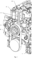
- FIG.1 and 2 an internal combustion engine with fan attachments such as fans, pulleys and fan bearings 5 is shown, which noticeably reduces the overall length of the engine. This is achieved by integrating the height-adjustable fan bracket 3 into the cylinder crankcase 1 and the cylinder head 2.
- the fan attachments including fans, pulleys and fan bearings 5 are then attached directly to the cylinder crankcase 1 and/or the cylinder head 2.
- the fan bearing 5 runs in two internal guide grooves in the manner of a T-slot nut or a T-slot stone 11 - also called a sliding stone - a threaded hole or, in this case, four threaded holes are arranged in the fan bearing 5 to accommodate the screws 10.
- a stone like this is used, for example, to connect the machine table and the workpiece in a machine tool. It is axially movable in a T-slot of the table or, here, in the guide groove 6, which is arranged in the cylinder crankcase 1 and/or the cylinder head 2. It creates a screwing point for the workpiece using a special screw and can be adjusted in height within a given hole pitch 7.
- the pre-tension of an elastic V-ribbed belt 8 is achieved by screwing the fan attachments including fan, pulleys and The fan bearing 5 is brought into the desired position using an assembly/clamping tool 9 and then screwed to the cylinder crankcase 1 and/or the cylinder head 2 using screws 10.
- the assembly/clamping tool 9 which consists of an abutment that can be screwed to the cylinder head 2 above the guide groove 6 and that has a guide hole for receiving a rack that is screwed into a thread in the sliding block 11, is arranged so as to be removable. A nut is arranged on the rack on the abutment, by means of which the rack can adjust the height of the fan bearing 5. The assembly/clamping tool 9 can be removed after the fan bearing 5 has been fixed in its working position using the screws 10.
- the four through holes for receiving the screws 10 on the sliding block 11 have threads, so that the sliding block 11 is clamped against the guide grooves 6 by means of the screws 10, so that the fan bearing 5 can be arranged at a variable height.
- Fig.3 the internal combustion engine is switched off Fig.1 and 2 with the fan bearing 5 removed.
- the back of the fan bearing 5 is designed like a sliding block 11.
- the fan bearing is guided in the guide grooves 6 of the cylinder head 2 and the cylinder crankcase 1 and is fixed in the working position with the screws 10 in the threads of the hole 7.
- Fig.4 shows a plan view of the front side of the internal combustion engine with the fan bearing 5.
- the arrangement of the sliding block 11 of the fan bearing 5 in the guide grooves 6, which are machined in the cylinder head 2 and the cylinder crankcase 1, can be seen.
Landscapes
- Engineering & Computer Science (AREA)
- General Engineering & Computer Science (AREA)
- Mechanical Engineering (AREA)
- Chemical & Material Sciences (AREA)
- Combustion & Propulsion (AREA)
- Devices For Conveying Motion By Means Of Endless Flexible Members (AREA)
Description
Die Erfindung betrifft eine Brennkraftmaschine mit einem Zylinderkurbelgehäuse und einem Zylinderkopf mit integriertem höhenverstellbarem Lüfteranbau für elastische Keilrippenriemen.The invention relates to an internal combustion engine with a cylinder crankcase and a cylinder head with integrated height-adjustable fan attachment for elastic V-ribbed belts.
Derartige Brennkraftmaschinen sind z. B. bekannt aus der der
In der japanischen ungeprüften Patentveröffentlichung
In der japanischen ungeprüften Patentveröffentlichung
Aus der
Aus der
Aus der
In der Offenlegungsschrift
Die
In der
Bei der Entwicklung von Brennkraftmaschinen wird auf die Kompaktheit dieser Motoren geachtet. Insbesondere die Länge des Motors ist entscheidend, um die Geräte, in die dieser Motor eingebaut werden soll, kompakt zu halten. Ein Kriterium für die Motorlänge ist das Zylinderkurbelgehäuse und der Zylinderkopf mit deren Lüfteranbau. Bekannte Konstruktionen zeigen höhenverstellbare Lüfterkonsolen, die vor bzw. an das Zylinderkurbelgehäuse und/oder vor bzw. an den Zylinderkopf geschraubt werden. Die Konsolen nehmen teilweise Spannelemente für den Keilrippenriemen auf. Alternativ werden Spannelemente für den Keilrippenriemen auf dem Zylinderkurbelgehäuse oder/und dem Zylinderkopf befestigt. Auf den Lüfterkonsolen sind die Lüfteranbauten befestigt. Die Lüfteranbauten nehmen den Lüfter inkl. Riemenscheibe und Lüfterlagerung auf. Dies erfordert einen ausreichend großen Bauraum.When developing internal combustion engines, attention is paid to the compactness of these engines. The length of the engine is particularly important in order to keep the devices in which this engine is to be installed compact. One criterion for the length of the engine is the cylinder crankcase and the cylinder head with their fan attachment. Known designs show height-adjustable fan brackets that are screwed in front of or onto the cylinder crankcase and/or in front of or onto the cylinder head. The brackets sometimes accommodate tensioning elements for the V-ribbed belt. Alternatively, tensioning elements for the V-ribbed belt are attached to the cylinder crankcase and/or the cylinder head. The fan attachments are attached to the fan brackets. The fan attachments accommodate the fan including the pulley and fan bearing. This requires a sufficiently large installation space.
Es ist somit eine Aufgabe der Erfindung, die aus dem Stand der Technik bekannten Ansätze unter Vermeidung der vorstehend beschriebenen Nachteile weiterzubilden. Es ist insbesondere eine Aufgabe der Erfindung, einen Lüfterantrieb bereitzustellen, der kostengünstig, komponentenschonend und mit geringem Bauraumbedarf realisierbar ist und Fertigung und Montage verbessert.It is therefore an object of the invention to further develop the approaches known from the prior art while avoiding the disadvantages described above. It is in particular an object of the invention to provide a fan drive that can be implemented cost-effectively, with minimal component wear and with a small installation space requirement and that improves production and assembly.
Diese Aufgaben werden durch Vorrichtungen mit den Merkmalen des unabhängigen Anspruchs gelöst. Vorteilhafte Ausführungsformen und Anwendungen der Erfindung ergeben sich aus den abhängigen Ansprüchen und werden in der folgenden Beschreibung unter teilweiser Bezugnahme auf die Fig. näher erläutert. Es zeigen:
- Fig. 1:
- Brennkraftmaschine mit Lüfteranbauten wie Lüfter, Riemenscheibe und Lüfterlagerung,
- Fig. 2:
- die Stirnseite der Brennkraftmaschine aus
Fig. 1 mit Blick auf den Lüfter, - Fig. 3:
- Brennkraftmaschine ohne Lüfteranbauten und demontierter Lüfterlagerung,
- Fig. 4:
- Draufsicht auf die Stirnseite der Brennkraftmaschine mit Lüfterlagerung.
- Fig.1:
- Internal combustion engine with fan attachments such as fan, pulley and fan bearing,
- Fig. 2:
- the front of the internal combustion engine
Fig.1 looking at the fan, - Fig. 3:
- Internal combustion engine without fan attachments and dismantled fan bearing,
- Fig.4:
- Top view of the front of the internal combustion engine with fan bearing.
In
Alternativ ist vorgesehen, dass die vier Durchgangsbohrungen zur Aufnahme der Schrauben 10 am Nutenstein 11 Gewinde aufweisen, so dass der Nutenstein 11 mittels der Schrauben 10 gegen die Führungsnuten 6 verspannt werden, so dass die Lüfterlagerung 5 in der Höhe variabel angeordnet werden kann.Alternatively, it is provided that the four through holes for receiving the
In
- 11
- ZylinderkurbelgehäuseCylinder crankcase
- 22
- ZylinderkopfCylinder head
- 33
- LüfterkonsoleFan console
- 55
- LüfterlagerungFan bearing
- 66
- FührungsnutenGuide grooves
- 77
- vorgegebener Lochstichpredefined hole stitch
- 88
- KeilrippenriemenV-ribbed belt
- 99
- Montage- /Spann-WerkzeugAssembly/clamping tool
- 1010
- SchraubenScrews
- 1111
- T-Nutenstein/ -mutterT-slot nut/slot nut
Claims (6)
- An internal combustion engine comprising:a cylinder crankcase (1);a cylinder head (2);at least one device for operating a fan, more specifically of a vehicle, more specifically of a utility vehicle, by means of which the fan is arranged so as to be displaceable relative to a crankshaft of the internal combustion engine,wherein the device for operating a fan comprises a fan bracket (3) and a fan bearing (5); anda belt drive, via which the fan can be operated, the belt drive having a first belt pulley and a second belt pulley, which are in a drive link pin via a belt (8), and the first belt pulley being arranged on the fan bearing (5),characterized in that the fan bearing (5) is designed as a T-slot block which is arranged to be axially displaceable in a guide groove (6) which is arranged in the cylinder crankcase (1) and/or in the cylinder head (2).
- The internal combustion engine according to claim 1,
characterized in that the belt (8) is a V-ribbed belt. - The internal combustion engine according to one or more of the preceding claims, characterized in that the fan bracket (3) has a hole pitch.
- The internal combustion engine according to one or more of the preceding claims, characterized in that the fan bracket (3) has an installation clamping tool (9).
- The internal combustion engine according to claim 4,
characterized in that the installation clamping tool (9) is designed such that it can be removed. - A method for operating an internal combustion engine,
characterized in that an internal combustion engine according to one or more of the preceding claims is being used.
Applications Claiming Priority (2)
| Application Number | Priority Date | Filing Date | Title |
|---|---|---|---|
| DE102019007007.0A DE102019007007A1 (en) | 2019-10-09 | 2019-10-09 | Internal combustion engine with a cylinder crankcase and a cylinder head with an integrated height-adjustable fan attachment for elastic V-ribbed belts |
| PCT/EP2020/000170 WO2021069089A1 (en) | 2019-10-09 | 2020-10-05 | Internal combustion engine with a cylinder crankcase and a cylinder head with integrated height-adjustable fan attachment for elastic v-ribbed belts |
Publications (2)
| Publication Number | Publication Date |
|---|---|
| EP4042004A1 EP4042004A1 (en) | 2022-08-17 |
| EP4042004B1 true EP4042004B1 (en) | 2024-09-11 |
Family
ID=72944091
Family Applications (1)
| Application Number | Title | Priority Date | Filing Date |
|---|---|---|---|
| EP20793262.5A Active EP4042004B1 (en) | 2019-10-09 | 2020-10-05 | Internal combustion engine with a cylinder crankcase and a cylinder head with integrated height-adjustable fan attachment for elastic v-ribbed belts |
Country Status (6)
| Country | Link |
|---|---|
| US (1) | US12085013B2 (en) |
| EP (1) | EP4042004B1 (en) |
| JP (1) | JP7564518B2 (en) |
| CN (1) | CN114423936B (en) |
| DE (1) | DE102019007007A1 (en) |
| WO (1) | WO2021069089A1 (en) |
Families Citing this family (1)
| Publication number | Priority date | Publication date | Assignee | Title |
|---|---|---|---|---|
| US20240068488A1 (en) * | 2022-08-30 | 2024-02-29 | Lombardini S.R.L. | Universal fan shaft mounting plate |
Family Cites Families (21)
| Publication number | Priority date | Publication date | Assignee | Title |
|---|---|---|---|---|
| US1002848A (en) * | 1908-06-27 | 1911-09-12 | Packard Motor Car Co | Motor-vehicle. |
| US1639449A (en) * | 1921-11-12 | 1927-08-16 | Int Harvester Co | Internal-combustion engine |
| US1530299A (en) * | 1923-07-24 | 1925-03-17 | Chilcott Thomas Robert Relleen | Circulating oil pump for internal-combustion engines |
| US2526242A (en) * | 1945-06-04 | 1950-10-17 | Hercules Motors Corp | Fan drive |
| US3362243A (en) * | 1967-02-14 | 1968-01-09 | Hunt Foods And Ind Inc | Engine cooling fan assembly |
| US3603296A (en) * | 1970-04-02 | 1971-09-07 | Gen Motors Corp | Engine camshaft and accessory drive |
| DE2318104A1 (en) | 1973-04-11 | 1974-10-24 | Luk Lamellen & Kupplungsbau | FAN DRIVE |
| JPS60121549U (en) * | 1984-01-24 | 1985-08-16 | トヨタ自動車株式会社 | Power transmission mechanism using V-ribbed belt |
| DE4216135A1 (en) * | 1991-05-16 | 1992-11-19 | Mazda Motor | CONTROL DEVICE FOR A ROTATION BODY FOR COOLING A MOTOR |
| JP3520115B2 (en) * | 1994-07-30 | 2004-04-19 | スズキ株式会社 | Fan mounting structure |
| DE19725216C1 (en) | 1997-06-15 | 1998-11-19 | Daimler Benz Ag | Device for driving units of an internal combustion engine |
| JP2001220771A (en) | 2000-02-10 | 2001-08-17 | Komatsu Engineering Kk | Construction vehicle |
| DE10324314B4 (en) | 2002-06-12 | 2014-02-13 | Behr Gmbh & Co. Kg | Fan drive for motor vehicles |
| DE10317507A1 (en) * | 2003-04-16 | 2004-11-04 | Daimlerchrysler Ag | Propulsion apparatus for cooling fan of motor vehicle, has pulley that is mounted to motor shaft, and which is axially displaceable along motor shaft |
| CN2744842Y (en) * | 2004-08-19 | 2005-12-07 | 安徽合力股份有限公司 | Internal direct driving pump device for internal combustion engine |
| JP2008031937A (en) | 2006-07-28 | 2008-02-14 | Yanmar Co Ltd | Auxiliary machine driving device |
| CN203769913U (en) * | 2014-03-05 | 2014-08-13 | 广西玉柴机器股份有限公司 | Engine fan layout and mounting structure |
| DE102015008721A1 (en) * | 2015-07-04 | 2017-01-05 | Man Truck & Bus Ag | Fan drive for a motor vehicle |
| CN205779251U (en) | 2016-06-07 | 2016-12-07 | 潍柴动力股份有限公司 | The adjustable for height motor front-end wheel system of fan |
| DE102016015152A1 (en) * | 2016-12-20 | 2018-06-21 | Daimler Ag | Fan arrangement for an internal combustion engine |
| CN207776980U (en) * | 2018-01-24 | 2018-08-28 | 中国重汽集团济南动力有限公司 | A kind of novel low-position fan bracket assembly |
-
2019
- 2019-10-09 DE DE102019007007.0A patent/DE102019007007A1/en not_active Ceased
-
2020
- 2020-10-05 US US17/767,571 patent/US12085013B2/en active Active
- 2020-10-05 EP EP20793262.5A patent/EP4042004B1/en active Active
- 2020-10-05 WO PCT/EP2020/000170 patent/WO2021069089A1/en not_active Ceased
- 2020-10-05 JP JP2022508576A patent/JP7564518B2/en active Active
- 2020-10-05 CN CN202080065225.9A patent/CN114423936B/en active Active
Also Published As
| Publication number | Publication date |
|---|---|
| JP2022550931A (en) | 2022-12-06 |
| EP4042004A1 (en) | 2022-08-17 |
| DE102019007007A1 (en) | 2021-04-15 |
| CN114423936A (en) | 2022-04-29 |
| WO2021069089A1 (en) | 2021-04-15 |
| US20240084729A1 (en) | 2024-03-14 |
| JP7564518B2 (en) | 2024-10-09 |
| US12085013B2 (en) | 2024-09-10 |
| CN114423936B (en) | 2024-08-23 |
Similar Documents
| Publication | Publication Date | Title |
|---|---|---|
| DE19807822B4 (en) | pivot bearing | |
| EP1875105B1 (en) | Traction mechanism drive, especially belt drive for secondary units of a combustion engine | |
| DE69301050T2 (en) | Eccentric crankshaft for an air compressor with displacement piston | |
| EP4042004B1 (en) | Internal combustion engine with a cylinder crankcase and a cylinder head with integrated height-adjustable fan attachment for elastic v-ribbed belts | |
| DE102017117352A1 (en) | OUTER SPRING FOR INCREASING THE VOLTAGE ON A BELT TENSIONER FOR A COMBUSTION ENGINE | |
| DE4202001A1 (en) | BELT DRIVE OF ELECTRICAL MACHINES | |
| EP1607657A2 (en) | Belt tensioning device and belt transmission with a belt tensioning device | |
| DE69936522T2 (en) | RIGID CRANKSHAFT SUPPORT AND ACTUATOR | |
| EP1913286B1 (en) | Belt drive | |
| EP3115242B1 (en) | Ventilator drive for a motor vehicle | |
| DE3724409A1 (en) | FUEL INJECTION PUMP FOR INTERNAL COMBUSTION ENGINES | |
| DE112015001284B4 (en) | Attachment structure for an engine accessory | |
| DE3819030A1 (en) | Oil pump arrangement for the forced-feed lubrication circuit of an engine operating at different speeds | |
| DE102006033270B4 (en) | Reciprocating internal combustion engine | |
| DE102011085594A1 (en) | Tensioning device for traction drive of internal combustion engine, has part that is pretensioned over intermediate spring element against another part, where actuator is coaxially placed with spring element within latter part | |
| DE102018109539B3 (en) | Self-aligning pendulum with spring-point displacement by wedge principle, endless traction mechanism and setting method for adjusting the clamping force of a pendulum clamp | |
| DE102008060931A1 (en) | Transmission housing for adjusting device for adjustment of compression ratio of internal combustion engine, has mounting element designed as attachment eyelet, where housing is defined in cylinder crankcase of internal combustion engine | |
| DE3626530C1 (en) | Arrangement of an assembly by means of the screw connection of a highly stressed machine part, especially in internal combustion engines | |
| EP3748193A2 (en) | Tensioning assembly with tensioning roller and device for adjusting a tensioning assembly | |
| WO2020078796A1 (en) | Hub-hub connection for a power unit | |
| DE102005003552B4 (en) | Crosshead engine | |
| DE102005031295B4 (en) | Drive device with two belt drives arranged on the front side of an internal combustion engine | |
| DE473677C (en) | Device for internal combustion engines with variable compression space, especially for experiments with aircraft engines | |
| AT521164B1 (en) | Internal combustion engine | |
| EP3772593B1 (en) | Motorised working tool with reinforced cooling fan casing |
Legal Events
| Date | Code | Title | Description |
|---|---|---|---|
| STAA | Information on the status of an ep patent application or granted ep patent |
Free format text: STATUS: UNKNOWN |
|
| STAA | Information on the status of an ep patent application or granted ep patent |
Free format text: STATUS: THE INTERNATIONAL PUBLICATION HAS BEEN MADE |
|
| PUAI | Public reference made under article 153(3) epc to a published international application that has entered the european phase |
Free format text: ORIGINAL CODE: 0009012 |
|
| STAA | Information on the status of an ep patent application or granted ep patent |
Free format text: STATUS: REQUEST FOR EXAMINATION WAS MADE |
|
| 17P | Request for examination filed |
Effective date: 20220325 |
|
| AK | Designated contracting states |
Kind code of ref document: A1 Designated state(s): AL AT BE BG CH CY CZ DE DK EE ES FI FR GB GR HR HU IE IS IT LI LT LU LV MC MK MT NL NO PL PT RO RS SE SI SK SM TR |
|
| DAV | Request for validation of the european patent (deleted) | ||
| DAX | Request for extension of the european patent (deleted) | ||
| STAA | Information on the status of an ep patent application or granted ep patent |
Free format text: STATUS: EXAMINATION IS IN PROGRESS |
|
| 17Q | First examination report despatched |
Effective date: 20230220 |
|
| GRAP | Despatch of communication of intention to grant a patent |
Free format text: ORIGINAL CODE: EPIDOSNIGR1 |
|
| STAA | Information on the status of an ep patent application or granted ep patent |
Free format text: STATUS: GRANT OF PATENT IS INTENDED |
|
| INTG | Intention to grant announced |
Effective date: 20240528 |
|
| GRAS | Grant fee paid |
Free format text: ORIGINAL CODE: EPIDOSNIGR3 |
|
| GRAA | (expected) grant |
Free format text: ORIGINAL CODE: 0009210 |
|
| STAA | Information on the status of an ep patent application or granted ep patent |
Free format text: STATUS: THE PATENT HAS BEEN GRANTED |
|
| AK | Designated contracting states |
Kind code of ref document: B1 Designated state(s): AL AT BE BG CH CY CZ DE DK EE ES FI FR GB GR HR HU IE IS IT LI LT LU LV MC MK MT NL NO PL PT RO RS SE SI SK SM TR |
|
| REG | Reference to a national code |
Ref country code: GB Ref legal event code: FG4D Free format text: NOT ENGLISH |
|
| REG | Reference to a national code |
Ref country code: CH Ref legal event code: EP |
|
| REG | Reference to a national code |
Ref country code: DE Ref legal event code: R096 Ref document number: 502020009223 Country of ref document: DE |
|
| REG | Reference to a national code |
Ref country code: IE Ref legal event code: FG4D Free format text: LANGUAGE OF EP DOCUMENT: GERMAN |
|
| REG | Reference to a national code |
Ref country code: LT Ref legal event code: MG9D |
|
| PG25 | Lapsed in a contracting state [announced via postgrant information from national office to epo] |
Ref country code: NO Free format text: LAPSE BECAUSE OF FAILURE TO SUBMIT A TRANSLATION OF THE DESCRIPTION OR TO PAY THE FEE WITHIN THE PRESCRIBED TIME-LIMIT Effective date: 20241211 |
|
| REG | Reference to a national code |
Ref country code: NL Ref legal event code: MP Effective date: 20240911 |
|
| PG25 | Lapsed in a contracting state [announced via postgrant information from national office to epo] |
Ref country code: GR Free format text: LAPSE BECAUSE OF FAILURE TO SUBMIT A TRANSLATION OF THE DESCRIPTION OR TO PAY THE FEE WITHIN THE PRESCRIBED TIME-LIMIT Effective date: 20241212 Ref country code: FI Free format text: LAPSE BECAUSE OF FAILURE TO SUBMIT A TRANSLATION OF THE DESCRIPTION OR TO PAY THE FEE WITHIN THE PRESCRIBED TIME-LIMIT Effective date: 20240911 |
|
| PG25 | Lapsed in a contracting state [announced via postgrant information from national office to epo] |
Ref country code: BG Free format text: LAPSE BECAUSE OF FAILURE TO SUBMIT A TRANSLATION OF THE DESCRIPTION OR TO PAY THE FEE WITHIN THE PRESCRIBED TIME-LIMIT Effective date: 20240911 |
|
| PG25 | Lapsed in a contracting state [announced via postgrant information from national office to epo] |
Ref country code: LV Free format text: LAPSE BECAUSE OF FAILURE TO SUBMIT A TRANSLATION OF THE DESCRIPTION OR TO PAY THE FEE WITHIN THE PRESCRIBED TIME-LIMIT Effective date: 20240911 |
|
| PG25 | Lapsed in a contracting state [announced via postgrant information from national office to epo] |
Ref country code: HR Free format text: LAPSE BECAUSE OF FAILURE TO SUBMIT A TRANSLATION OF THE DESCRIPTION OR TO PAY THE FEE WITHIN THE PRESCRIBED TIME-LIMIT Effective date: 20240911 |
|
| PG25 | Lapsed in a contracting state [announced via postgrant information from national office to epo] |
Ref country code: RS Free format text: LAPSE BECAUSE OF FAILURE TO SUBMIT A TRANSLATION OF THE DESCRIPTION OR TO PAY THE FEE WITHIN THE PRESCRIBED TIME-LIMIT Effective date: 20241211 Ref country code: ES Free format text: LAPSE BECAUSE OF FAILURE TO SUBMIT A TRANSLATION OF THE DESCRIPTION OR TO PAY THE FEE WITHIN THE PRESCRIBED TIME-LIMIT Effective date: 20240911 |
|
| PG25 | Lapsed in a contracting state [announced via postgrant information from national office to epo] |
Ref country code: RS Free format text: LAPSE BECAUSE OF FAILURE TO SUBMIT A TRANSLATION OF THE DESCRIPTION OR TO PAY THE FEE WITHIN THE PRESCRIBED TIME-LIMIT Effective date: 20241211 Ref country code: NO Free format text: LAPSE BECAUSE OF FAILURE TO SUBMIT A TRANSLATION OF THE DESCRIPTION OR TO PAY THE FEE WITHIN THE PRESCRIBED TIME-LIMIT Effective date: 20241211 Ref country code: LV Free format text: LAPSE BECAUSE OF FAILURE TO SUBMIT A TRANSLATION OF THE DESCRIPTION OR TO PAY THE FEE WITHIN THE PRESCRIBED TIME-LIMIT Effective date: 20240911 Ref country code: HR Free format text: LAPSE BECAUSE OF FAILURE TO SUBMIT A TRANSLATION OF THE DESCRIPTION OR TO PAY THE FEE WITHIN THE PRESCRIBED TIME-LIMIT Effective date: 20240911 Ref country code: GR Free format text: LAPSE BECAUSE OF FAILURE TO SUBMIT A TRANSLATION OF THE DESCRIPTION OR TO PAY THE FEE WITHIN THE PRESCRIBED TIME-LIMIT Effective date: 20241212 Ref country code: FI Free format text: LAPSE BECAUSE OF FAILURE TO SUBMIT A TRANSLATION OF THE DESCRIPTION OR TO PAY THE FEE WITHIN THE PRESCRIBED TIME-LIMIT Effective date: 20240911 Ref country code: ES Free format text: LAPSE BECAUSE OF FAILURE TO SUBMIT A TRANSLATION OF THE DESCRIPTION OR TO PAY THE FEE WITHIN THE PRESCRIBED TIME-LIMIT Effective date: 20240911 Ref country code: BG Free format text: LAPSE BECAUSE OF FAILURE TO SUBMIT A TRANSLATION OF THE DESCRIPTION OR TO PAY THE FEE WITHIN THE PRESCRIBED TIME-LIMIT Effective date: 20240911 |
|
| PG25 | Lapsed in a contracting state [announced via postgrant information from national office to epo] |
Ref country code: NL Free format text: LAPSE BECAUSE OF FAILURE TO SUBMIT A TRANSLATION OF THE DESCRIPTION OR TO PAY THE FEE WITHIN THE PRESCRIBED TIME-LIMIT Effective date: 20240911 |
|
| PG25 | Lapsed in a contracting state [announced via postgrant information from national office to epo] |
Ref country code: PT Free format text: LAPSE BECAUSE OF FAILURE TO SUBMIT A TRANSLATION OF THE DESCRIPTION OR TO PAY THE FEE WITHIN THE PRESCRIBED TIME-LIMIT Effective date: 20250113 Ref country code: IS Free format text: LAPSE BECAUSE OF FAILURE TO SUBMIT A TRANSLATION OF THE DESCRIPTION OR TO PAY THE FEE WITHIN THE PRESCRIBED TIME-LIMIT Effective date: 20250111 |
|
| PG25 | Lapsed in a contracting state [announced via postgrant information from national office to epo] |
Ref country code: RO Free format text: LAPSE BECAUSE OF FAILURE TO SUBMIT A TRANSLATION OF THE DESCRIPTION OR TO PAY THE FEE WITHIN THE PRESCRIBED TIME-LIMIT Effective date: 20240911 Ref country code: SM Free format text: LAPSE BECAUSE OF FAILURE TO SUBMIT A TRANSLATION OF THE DESCRIPTION OR TO PAY THE FEE WITHIN THE PRESCRIBED TIME-LIMIT Effective date: 20240911 |
|
| PG25 | Lapsed in a contracting state [announced via postgrant information from national office to epo] |
Ref country code: EE Free format text: LAPSE BECAUSE OF FAILURE TO SUBMIT A TRANSLATION OF THE DESCRIPTION OR TO PAY THE FEE WITHIN THE PRESCRIBED TIME-LIMIT Effective date: 20240911 |
|
| PG25 | Lapsed in a contracting state [announced via postgrant information from national office to epo] |
Ref country code: PL Free format text: LAPSE BECAUSE OF FAILURE TO SUBMIT A TRANSLATION OF THE DESCRIPTION OR TO PAY THE FEE WITHIN THE PRESCRIBED TIME-LIMIT Effective date: 20240911 Ref country code: CZ Free format text: LAPSE BECAUSE OF FAILURE TO SUBMIT A TRANSLATION OF THE DESCRIPTION OR TO PAY THE FEE WITHIN THE PRESCRIBED TIME-LIMIT Effective date: 20240911 |
|
| PG25 | Lapsed in a contracting state [announced via postgrant information from national office to epo] |
Ref country code: SK Free format text: LAPSE BECAUSE OF FAILURE TO SUBMIT A TRANSLATION OF THE DESCRIPTION OR TO PAY THE FEE WITHIN THE PRESCRIBED TIME-LIMIT Effective date: 20240911 Ref country code: IT Free format text: LAPSE BECAUSE OF FAILURE TO SUBMIT A TRANSLATION OF THE DESCRIPTION OR TO PAY THE FEE WITHIN THE PRESCRIBED TIME-LIMIT Effective date: 20240911 |
|
| REG | Reference to a national code |
Ref country code: CH Ref legal event code: PL |
|
| REG | Reference to a national code |
Ref country code: DE Ref legal event code: R097 Ref document number: 502020009223 Country of ref document: DE |
|
| PG25 | Lapsed in a contracting state [announced via postgrant information from national office to epo] |
Ref country code: MC Free format text: LAPSE BECAUSE OF FAILURE TO SUBMIT A TRANSLATION OF THE DESCRIPTION OR TO PAY THE FEE WITHIN THE PRESCRIBED TIME-LIMIT Effective date: 20240911 |
|
| PG25 | Lapsed in a contracting state [announced via postgrant information from national office to epo] |
Ref country code: DK Free format text: LAPSE BECAUSE OF FAILURE TO SUBMIT A TRANSLATION OF THE DESCRIPTION OR TO PAY THE FEE WITHIN THE PRESCRIBED TIME-LIMIT Effective date: 20240911 |
|
| PG25 | Lapsed in a contracting state [announced via postgrant information from national office to epo] |
Ref country code: BE Free format text: LAPSE BECAUSE OF NON-PAYMENT OF DUE FEES Effective date: 20241031 Ref country code: LU Free format text: LAPSE BECAUSE OF NON-PAYMENT OF DUE FEES Effective date: 20241005 |
|
| PLBE | No opposition filed within time limit |
Free format text: ORIGINAL CODE: 0009261 |
|
| STAA | Information on the status of an ep patent application or granted ep patent |
Free format text: STATUS: NO OPPOSITION FILED WITHIN TIME LIMIT |
|
| PG25 | Lapsed in a contracting state [announced via postgrant information from national office to epo] |
Ref country code: CH Free format text: LAPSE BECAUSE OF NON-PAYMENT OF DUE FEES Effective date: 20241031 |
|
| REG | Reference to a national code |
Ref country code: BE Ref legal event code: MM Effective date: 20241031 |
|
| 26N | No opposition filed |
Effective date: 20250612 |
|
| GBPC | Gb: european patent ceased through non-payment of renewal fee |
Effective date: 20241211 |
|
| PG25 | Lapsed in a contracting state [announced via postgrant information from national office to epo] |
Ref country code: SE Free format text: LAPSE BECAUSE OF FAILURE TO SUBMIT A TRANSLATION OF THE DESCRIPTION OR TO PAY THE FEE WITHIN THE PRESCRIBED TIME-LIMIT Effective date: 20240911 |
|
| PG25 | Lapsed in a contracting state [announced via postgrant information from national office to epo] |
Ref country code: GB Free format text: LAPSE BECAUSE OF NON-PAYMENT OF DUE FEES Effective date: 20241211 |
|
| PG25 | Lapsed in a contracting state [announced via postgrant information from national office to epo] |
Ref country code: FR Free format text: LAPSE BECAUSE OF NON-PAYMENT OF DUE FEES Effective date: 20241111 |
|
| PG25 | Lapsed in a contracting state [announced via postgrant information from national office to epo] |
Ref country code: IE Free format text: LAPSE BECAUSE OF NON-PAYMENT OF DUE FEES Effective date: 20241005 |
|
| PGFP | Annual fee paid to national office [announced via postgrant information from national office to epo] |
Ref country code: DE Payment date: 20251027 Year of fee payment: 6 |
|
| PGFP | Annual fee paid to national office [announced via postgrant information from national office to epo] |
Ref country code: AT Payment date: 20260113 Year of fee payment: 5 |
|
| PG25 | Lapsed in a contracting state [announced via postgrant information from national office to epo] |
Ref country code: CY Free format text: LAPSE BECAUSE OF FAILURE TO SUBMIT A TRANSLATION OF THE DESCRIPTION OR TO PAY THE FEE WITHIN THE PRESCRIBED TIME-LIMIT; INVALID AB INITIO Effective date: 20201005 |