EP4041965B1 - Bodenplatte zur formung eines bodenbelags - Google Patents
Bodenplatte zur formung eines bodenbelags Download PDFInfo
- Publication number
- EP4041965B1 EP4041965B1 EP20793446.4A EP20793446A EP4041965B1 EP 4041965 B1 EP4041965 B1 EP 4041965B1 EP 20793446 A EP20793446 A EP 20793446A EP 4041965 B1 EP4041965 B1 EP 4041965B1
- Authority
- EP
- European Patent Office
- Prior art keywords
- locking
- floor panel
- plane
- floor
- angle
- Prior art date
- Legal status (The legal status is an assumption and is not a legal conclusion. Google has not performed a legal analysis and makes no representation as to the accuracy of the status listed.)
- Active
Links
Images


Classifications
-
- E—FIXED CONSTRUCTIONS
- E04—BUILDING
- E04F—FINISHING WORK ON BUILDINGS, e.g. STAIRS, FLOORS
- E04F15/00—Flooring
- E04F15/02—Flooring or floor layers composed of a number of similar elements
- E04F15/02038—Flooring or floor layers composed of a number of similar elements characterised by tongue and groove connections between neighbouring flooring elements
-
- E—FIXED CONSTRUCTIONS
- E04—BUILDING
- E04F—FINISHING WORK ON BUILDINGS, e.g. STAIRS, FLOORS
- E04F2201/00—Joining sheets or plates or panels
- E04F2201/01—Joining sheets, plates or panels with edges in abutting relationship
- E04F2201/0107—Joining sheets, plates or panels with edges in abutting relationship by moving the sheets, plates or panels substantially in their own plane, perpendicular to the abutting edges
- E04F2201/0115—Joining sheets, plates or panels with edges in abutting relationship by moving the sheets, plates or panels substantially in their own plane, perpendicular to the abutting edges with snap action of the edge connectors
-
- E—FIXED CONSTRUCTIONS
- E04—BUILDING
- E04F—FINISHING WORK ON BUILDINGS, e.g. STAIRS, FLOORS
- E04F2201/00—Joining sheets or plates or panels
- E04F2201/01—Joining sheets, plates or panels with edges in abutting relationship
- E04F2201/0123—Joining sheets, plates or panels with edges in abutting relationship by moving the sheets, plates or panels parallel to the abutting edges
-
- E—FIXED CONSTRUCTIONS
- E04—BUILDING
- E04F—FINISHING WORK ON BUILDINGS, e.g. STAIRS, FLOORS
- E04F2201/00—Joining sheets or plates or panels
- E04F2201/01—Joining sheets, plates or panels with edges in abutting relationship
- E04F2201/0138—Joining sheets, plates or panels with edges in abutting relationship by moving the sheets, plates or panels perpendicular to the main plane
- E04F2201/0146—Joining sheets, plates or panels with edges in abutting relationship by moving the sheets, plates or panels perpendicular to the main plane with snap action of the edge connectors
-
- E—FIXED CONSTRUCTIONS
- E04—BUILDING
- E04F—FINISHING WORK ON BUILDINGS, e.g. STAIRS, FLOORS
- E04F2201/00—Joining sheets or plates or panels
- E04F2201/01—Joining sheets, plates or panels with edges in abutting relationship
- E04F2201/0153—Joining sheets, plates or panels with edges in abutting relationship by rotating the sheets, plates or panels around an axis which is parallel to the abutting edges, possibly combined with a sliding movement
- E04F2201/0161—Joining sheets, plates or panels with edges in abutting relationship by rotating the sheets, plates or panels around an axis which is parallel to the abutting edges, possibly combined with a sliding movement with snap action of the edge connectors
-
- E—FIXED CONSTRUCTIONS
- E04—BUILDING
- E04F—FINISHING WORK ON BUILDINGS, e.g. STAIRS, FLOORS
- E04F2201/00—Joining sheets or plates or panels
- E04F2201/02—Non-undercut connections, e.g. tongue and groove connections
- E04F2201/023—Non-undercut connections, e.g. tongue and groove connections with a continuous tongue or groove
-
- E—FIXED CONSTRUCTIONS
- E04—BUILDING
- E04F—FINISHING WORK ON BUILDINGS, e.g. STAIRS, FLOORS
- E04F2201/00—Joining sheets or plates or panels
- E04F2201/03—Undercut connections, e.g. using undercut tongues or grooves
-
- E—FIXED CONSTRUCTIONS
- E04—BUILDING
- E04F—FINISHING WORK ON BUILDINGS, e.g. STAIRS, FLOORS
- E04F2201/00—Joining sheets or plates or panels
- E04F2201/04—Other details of tongues or grooves
- E04F2201/042—Other details of tongues or grooves with grooves positioned on the rear-side of the panel
-
- E—FIXED CONSTRUCTIONS
- E04—BUILDING
- E04F—FINISHING WORK ON BUILDINGS, e.g. STAIRS, FLOORS
- E04F2201/00—Joining sheets or plates or panels
- E04F2201/04—Other details of tongues or grooves
- E04F2201/043—Other details of tongues or grooves with tongues and grooves being formed by projecting or recessed parts of the panel layers
Definitions
- the present invention relates to a floor panel for the forming of a floor covering, in particular for the forming of a floor covering which can be installed on a surface.
- the invention relates to floor panels provided on at least two opposite edges with coupling parts that allow the floor panels to be mechanically coupled.
- floor panels are described for instance in WO97/47834 , WO01/98603 , US 6.769.219 , WO2006/032398 , DE 102009019492 , US 2004/250492 , US 8978335 , and WO 2004/074597 .
- the purpose of the invention is to provide floor panels that can be more easily coupled- in other words with less force - when installing the floor covering.
- the invention relates to a floor panel for the forming of a floor covering as defined in claim 1.
- This floor panel comprises a substrate and a decorative layer.
- the floor panel is rectangular, either oblong or square, so it contains a first pair of opposite edges and a second pair of opposite edges.
- the first pair of opposite edges contains first coupling parts that allow several of such floor panels to be coupled together.
- These first coupling parts constitute a first locking system which, in a coupled condition of two such floor panels, creates a locking in the plane of the floor panels and perpendicular to the relevant edges, and also a second locking system which, in a coupled condition of two such floor panels, creates a locking across the panel face.
- first coupling parts are mainly in the material of the floor panel itself, and preferably in said substrate.
- these first coupling parts contain locking parts which, in the coupled condition, prevent the first coupling parts from sliding apart.
- Said locking parts are provided with locking planes.
- the locking part of the coupling part on the first edge of the first pair of opposite edges contains a first and a second locking plane.
- the first and second locking planes are adjacent, while the first locking plane and the second locking plane form a convex part of the coupling parts to which these locking planes belong.
- this enclosed angle is greater than 100°, more preferably greater than 120°, more preferably greater than 140°.
- the first locking plane and the second locking plane are separated by a bending line or a curved bending plane.
- the locking part of the coupling part on the second edge of the first pair of opposite edges contains a third and a fourth locking plane.
- the third and fourth locking planes are adjacent.
- the third locking plane and the fourth locking plane form a concave part of the coupling part to which these locking planes belong.
- this enclosed angle is greater than 100°, more preferably greater than 120°, more preferably greater than 140°.
- the third and fourth locking planes are separated by a bending line or a curved bending plane.
- the first locking plane is closer to the top of the floor panel than the second locking plane.
- the angle between the first locking plane and the floor panel surface is smaller than the angle between the second locking plane and the floor panel surface.
- the angle between the third locking plane and the floor panel surface is smaller than the angle between the fourth locking plane and the floor panel surface.
- the second locking plane is provided for interaction with the fourth locking plane of a coupled similar panel.
- the first locking plane is provided for interaction with the third locking plane of a coupled similar panel.
- Floor panels according to the invention can be installed more easily, because less force must be overcome to mechanically couple the first coupling parts - so two panels - together; yet the coupling strength will still be sufficiently high. This means that the pulling force required to pull coupled panels apart horizontally, is still sufficiently high.
- the angle between the first locking plane and the floor panel surface is at least 10° and less than 20° smaller than the angle between the second locking plane and the floor panel surface. This reduces the force required to mechanically couple the first two coupling parts - so two panels - together, while still creating proper coupling between the panels in a horizontal direction. This means that the pulling force required to pull coupled panels apart horizontally, is still sufficiently high.
- the angle between the third locking plane and the floor panel surface is at least 10° - and preferably less than 20° - smaller than the angle between the fourth locking plane and the floor panel surface.
- Such embodiments reduce the force required to mechanically couple the first two coupling parts - so two panels - together, while still creating proper coupling between the panels in a horizontal direction. This means that the pulling force required to pull coupled panels apart horizontally, is still sufficiently high.
- the first, second, third, and fourth locking planes are all located in the lower half of the floor panel thickness. This additionally facilitates the mechanical coupling of two panels.
- the area of the first locking plane is larger than the area of the second locking area. Such embodiments will even further reduce the force required to mechanically couple two such panels together.
- the area of the second locking plane is at least one third, preferably at least half, of the area of the first locking plane.
- Such embodiments offer a balance between on the one hand mechanically coupling the panels with low force, while on the other hand the coupling is sufficiently strong in the horizontal direction.
- the area of the third locking plane is larger than the area of the fourth locking plane. Such embodiments will even further reduce the force required to mechanically couple two such panels together.
- the area of the fourth locking plane is at least one third, preferably at least half, of the area of the third locking plane.
- Such embodiments offer a balance between on the one hand mechanically coupling the panels at low force, while on the other hand the coupling is sufficiently strong in the horizontal direction.
- the enclosed angle between the first and the second locking planes is smaller than the enclosed angle between the third and fourth locking planes.
- the tolerances on production of the first coupling parts may be compensated, while still panels are realized that can more easily be installed while a coupling with sufficient tensile strength in the horizontal direction of the coupling is realized.
- the difference between on the one hand the angle between the first locking plane and the floor panel surface and on the other hand the angle between the third locking plane and the fourth panel surface is greater than the difference between on the one hand the angle between the second locking plane and the floor panel surface and on the other hand the angle between the fourth locking plane and the floor panel surface.
- the difference between on the one hand the angle between the second locking plane and the floor panel surface and on the other hand the angle between the fourth locking plane and the floor panel surface in an absolute value is smaller than 3°, preferably in absolute value smaller than 2°.
- Such embodiments ensure that, when coupled, there is a secured contact between the second and fourth locking planes, rather than directly between the first and second locking planes. This is useful to obtain high values of the tensile strength with which the panels are coupled in a horizontal direction.
- the coupling part on the first edge of the first pair of opposite edges contains a horizontal-facing lip - preferably at the underside of the floor panel - and an upward-facing hook at the distal end of the lip.
- the first and the second locking plane are located on the inside of this upward-facing hook.
- the horizontal line in the vertical direction is centered between the first and the second locking plane in the lower half of the distance between the highest point of the upward-facing hook and the lowest point of the top of the lip. More preferably, this line is located in the lower 40% of the distance between the highest point of the upward-facing hook and the lowest point of the upper lip.
- the first coupling parts are configured to allow two such panels to be coupled together on these edges by means of a tilting motion and/or by means of horizontal sliding.
- the angle between the second locking plane and the floor panel surface is between 48° and 72°, more preferably this angle is greater than 55°. More preferably, this angle is less than 65°. Such embodiments provide sufficient strength in the horizontal direction of the coupling.
- the first coupling parts are made up of a tongue and a groove containing the locking parts.
- the first coupling parts are configured to allow two such floor panels to be mechanically coupled at these edges by means of horizontal sliding and/or by means of tilting.
- Such horizontally coupling floor panels according to the invention can be slid together horizontally with less effort, i.e. with less force.
- the groove is bordered by a lower lip and an upper lip - more preferably the lower lip extends sideways beyond the distal end of the upper lip - and the lower lip contains an upward-facing hook at its distal end.
- the first and the second locking plane are located on the inside of this upward-facing hook.
- the lower lip in coupled condition is at least partially elastically bent and thus produces a clamping force which forces the coupled floor panels together; while the floor panels are pressed together on or close to the floor panel surfaces. This provides a stronger coupling of the floor panels.
- the first coupling parts are configured so that in coupled condition the horizontal distance between on the one hand the vertical line through the center in a vertical direction between the first and the second locking planes and on the other hand the plane on or near the surface of the coupled panels where the coupled panels form a sealed locking, is smaller than 5.5 mm, more preferably smaller than 5 mm, more preferably smaller than 4 mm.
- floor panels with such short first coupling parts require a higher coupling force than floor panels with longer first coupling part.
- the invention ensures that such panels with short first coupling parts can still be mechanically coupled with less effort (i.e. by applying less force), while the strength of the coupling in the horizontal direction is still up to sufficient.
- the floor panel is oblong, and the first pair of opposite edges are on the long sides of the floor panel.
- the floor panel is oblong, and the first pair of opposite edges are on the short sides of the floor panel.
- the second pair of opposite edges contain second coupling parts that allow several of such floor panels to be coupled together.
- these second coupling parts constitute a third locking system which, when two of such floor panels are coupled, creates a lock in the plane of the floor panels and perpendicular to said edges, and also a fourth locking system which, when two of such floor panels are coupled, creates a lock across the plane of the panels.
- These second coupling parts at the second pair of opposite edges are mainly realized in the material of the floor panel itself, and more specifically in said substrate.
- the second coupling parts at the second pair of edges are configured to allow coupling of two such panels by means of a tilting motion and/or by means of horizontal sliding.
- the second coupling parts at the second pair of edges are configured to allow coupling of two of such panels at these edges by means of horizontal sliding.
- the second coupling parts at the second pair of edges are configured to allow coupling of two of such floor panels at these edges by means of a downward motion of one panel relative to the other one.
- the first coupling parts are configured to allow coupling of these first coupling parts by means of a tilting motion
- such floor panels can be installed to form a floor covering by means of what is known as "fold-down" motion.
- second coupling parts at the second pair of edges are configured to allow coupling two such floor panels at the these edges by means of a downward motion of one panel relative to the other one
- said second coupling parts are formed substantially from the material of said substrate and configured as one whole with it.
- the third locking system is at least formed from a downward-facing upper hook-shaped section located on one edge of said pair of opposite edges, and also from an upward-facing lower hook-shaped section located on the other opposite edge of said pair of opposite edges.
- the hook-shaped parts may be hooked together by means of said downward motion.
- Said hook-shaped part consists of a lip with a downward-facing locking element, while said upper hook-shaped part consists of a lip with an upward-facing locking element.
- the fourth locking system should preferably contain, in at least one or more coupling parts, one or more protrusions that engage in one or more undercuts in the other of the second coupling parts of the coupled floor panel.
- a separate locking part is provided by means of a movable and/or deformable insert that provides a vertical locking with the insert engaging in undercuts in both coupled edges of coupled floor panels.
- the second coupling parts at the second pair of edges have the characteristics as described in any embodiment for the first coupling parts.
- Such floor panels allow both pairs of edges to be coupled with less force, while still obtaining a sufficiently strong horizontal coupling.
- the panel is oblong, and the second pair of opposite edges is located on the short side of the floor panel.
- the angle with the surface of the floor panel of the second locking plane of the first coupling parts is smaller - and preferably at least 5° smaller - than the angle with the surface of the floor panel of the second locking plane of the second coupling parts.
- the second coupling parts are located at the short side of the floor panel.
- the force per unit of length to be coupled is higher on the short side than on the long sides, because of the higher angle of the second locking plane of the second coupling parts than the angle of the second locking plane of the first coupling parts. Because of the (much) smaller length to be coupled on the short side of the floor panel, this is not a disadvantage (the total force required to couple is equal to the force per unit of length to be coupled multiplied by the length to be coupled), while a higher strength is obtained in the horizontal direction of this coupling at the short side. It should also be noted that the edges of floor panels are never completely straight, which requires additional coupling force. Such irregularities are more likely to occur on the long side, which makes it interesting to design the configuration of the coupling parts at the pair of edges at the side in such a way that less force is required to couple them.
- the floor panel substrate is preferably made up of several layers.
- the floor panel is substantially composed of one or more base layers and at least one top layer.
- the floor panel should preferably contain a laminate panel with the substrate comprising either MDF (Medium Density Fiberboard) or comprising HDF (High Density Fiberboard).
- MDF Medium Density Fiberboard
- HDF High Density Fiberboard
- the floor panel is an engineered-wood panel.
- the floor panel is more than 4.5 mm thick.
- the floor panel is a resilient floor panel, preferably of the flexible type.
- Flexible floor panels refers to floor panels for which it applies that when, in the case of a rectangular panel, for example less than 50 centimeters wide, they are clamped on one of the short sides of the panel, extending over a length of 100 centimeters and not supported, the panels deflect under their own weight, with a deflection of at least 10 centimeters at the free end relative to the clamped end. For this deflection, a deflection time of 10 seconds is considered, starting from that horizontal position of the panel.
- a flexible or resilient synthetic floor panel according to the invention preferably has one of the following characteristics:
- soft PVC is a term that expresses the fact that it refers to flexible PVC, in other words PVC that is relatively easily bendable.
- the concept of soft PVC is commonly known in the technique.
- This soft PVC consists of PVC that has been plasticized, preferably by plasticizers added during the production process. Depending on the quantity of added plasticizer, different degrees of flexibility may be achieved.
- a plasticizer shall be understood to mean any substance which results in a more flexible PVC when added. Typical examples include phthalate plasticizers and isosorbide plasticizers.
- PVC that has been plasticized may of course also include PVC, or a compound based on PVC, which, for example because it has been modified, has the characteristic of being flexible in itself.
- the substrate comprises a thermoplastic matrix material, preferably polyvinyl chloride (PVC) - more preferably the substrate comprises a layer comprising foamed PVC, polypropylene (PP) or polyethylene (PE). More preferably, the substrate contains one or more filling agents, preferably selected from the list of stone, wood fiber, chalk, limestone and lime.
- the substrate is preferably provided with at least one reinforcement layer, preferably of fiberglass.
- the floor panel is a Luxury Vinyl Tile (LVT).
- LVT Luxury Vinyl Tile
- the floor panel is a Stone Plastic Composite (SPC) or a Wood Plastic Composite (WPC).
- SPC Stone Plastic Composite
- WPC Wood Plastic Composite
- a floor panel according to the invention of the resilient type or of the flexible type, has a thickness of less than or equal to 4.5 millimeters; more preferably less than or equal to 4 millimeters.
- Figure 1 schematically shows a top view of a floor panel according to the invention.
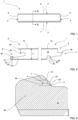
- Figure 2 shows the cross-section according to line II-II of the floor panel according to the invention of figure 1.
- Figures 3 and 4 show details of the coupling parts of the floor panel of figures 1 and 2 .
- Figure 5 shows two floor panels according to figures 1 and 2 in coupled condition.
- Figure 6 shows a detail of the coupling of figure 5 .
- the floor panel (1) illustrated in figures 1-8 is a floor panel for the forming of the floor covering.
- the floor panel has a thickness T.
- This floor panel (1) contains a substrate (10) - for example of HDF (High Density Fiberboard) and a decorative layer (12).
- the floor panel (1) in the example is rectangular. It has a first pair of opposite edges (2, 3) and a second pair of opposite edges (4, 5).
- the first pair of opposite edges (2, 3) contains first coupling parts (6, 7) which allow several of these floor panels (1) to be coupled together, as shown in figure 5 , by means of tilting motion or by means of horizontal sliding the coupling parts into each other.
- first coupling parts (6, 7) constitute a first locking system which, in a coupled condition of two such floor panels, creates a locking in the plane of the floor panels and perpendicular to the relevant edges, and also a second locking system which, in a coupled condition of two such floor panels, creates a locking across the panel face.
- first coupling parts (6, 7) are created in the substrate (10).
- these first coupling parts contain locking parts which, in the coupled condition, prevent the first coupling parts from sliding apart.
- the first coupling parts consist of a tongue (40) and a groove (42) containing the locking parts.
- These first coupling parts are configured to allow two of such floor panels to be mechanically coupled to these edges by means of horizontal sliding and also by means of tilting.
- the groove (42) is bounded at the first pair of opposite edges by a lower lip (33) and an upper lip (44).
- the lower lip (33) extends sideways beyond the distal end of the upper lip (44).
- the lower lip (33) has an upward-facing hook (34) at its distal end.
- the locking parts are fitted with locking planes (21, 22, 23, 24).
- the locking part of the coupling part (6) at the first edge (2) of the first pair of opposite edges contains a first (21) and a second (22) locking plane.
- the first (21) and second (22) locking planes are located on the inside of the upward-facing hook (34).
- the first locking plane is closer to the top of the floor panel than the second locking plane.
- the first and second locking planes are adjacent, separated by a bending line (27).
- the first locking plane and the second locking plane form a concave section (30) of the coupling part to which these locking planes belong.
- the locking part of the coupling part (7) on the second edge (3) of the first pair of opposite edges contains a third (23) and a fourth (24) locking plane.
- the third (23) and fourth (24) locking planes are adjacent, separated by a bend (29).
- the third locking plane (23) and the fourth locking plane (24) form a concave section (28) of the coupling part to which these locking planes belong.
- the first, second, third and fourth locking planes are all located in the lower half of the floor panel thickness (T).
- the angle ⁇ 1 (in the example 47°) between the first locking plane (21) and the surface (15) of the floor panel is smaller than the angle ⁇ 2 (in the example 60°) between the second locking plane (22) and the surface (15) of the floor panel.
- the angle ⁇ 3 (in the example 50°) between the third locking plane (23) and the surface (15) of the floor panel is smaller than the angle ⁇ 4 (in the example 60°) between the fourth locking plane (24) and the surface (15) of the floor panel.
- the second locking plane is provided for interaction with the fourth locking plane of a coupled similar panel.
- the first locking plane is provided for interaction with the third locking plane of a coupled similar panel. Between the first and second locking planes there is an enclosed angle ⁇ of 165°. Between the third and fourth locking planes there is an enclosed angle ⁇ of 172°.
- the area of the first locking plane is larger than the area of the second locking plane.
- the area of the second locking plane is 42% of the area of the first locking plane.
- the area of the third locking plane is larger than the area of the fourth locking plane.
- the lower lip in coupled condition is partially elastically bent downward, resulting in a clamping force (F) that forces the linked floor panels together. This results in a tension force (F) which ensures that the floor panels are pressed together at or close to the surface of the floor panels.
- the first coupling parts of the example are configured so that in coupled condition (see figure 5 ) the horizontal distance (A) between on the one hand the vertical line (V 1 ) through the center in a vertical direction between the first and second locking planes and on the other hand the plane at or near the surface of the coupled panels where the connected panels are sealed together is 5 mm.
- the locking planes of the tongue (40) When coupling two such floor panels by a tilting motion, the locking planes of the tongue (40) must push against the locking planes on the inside of the upward-facing hook (34). Because the first locking plane has a lower angle to the surface of the floor panel than the second locking plane, and because the third locking plane has a lower angle to the surface of the floor panel than the fourth locking plane, the contact between the locking planes of the tongue and locking planes of the hook is effected later during the coupling process. This reduces the force required to realize this coupling by means of the tilting motion of the tongue (40) in the groove (42).
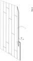
- Figure 7 shows the coupling of two floor panels on their short sides according to the example of figure 1 .
- the second pair of opposite edges (4, 5) of floor panel 1 contains second coupling parts (8, 9) that allow several of such floor panels (1) to be coupled together.
- These second coupling parts (8, 9) constitute a third locking system on the second pair of opposite edges (4, 5) which, in coupled condition of two such floor panels, creates a locking in the plane of the floor panels and perpendicular to the relevant edges, and also a fourth locking system which, in coupled condition of two such floor panels, creates a locking perpendicular to the panels plane.
- These second coupling parts on the second pair of opposite edges are mainly realized in the material of the floor panel itself, and more in particular in said substrate.
- the second coupling parts on the second pair of edges are configured to allow two such floor panels to be coupled together on these edges by means of a downward motion of one panel relative to the other.
- the third locking system consists of a downward-facing upper hook-shaped section (49) located on one edge of the said pair of opposite edges, and of an upward-facing lower hook-shaped (50) section located on the other opposite edge of said pair of opposite edges.
- the hook-shaped sections can be hooked together by means of a downward motion (M).
- the upper hook-shaped part (49) consists of a lip (52) with a downward-facing locking element (54).
- the lower hook-shaped part consists of a lip (56) with an upward-facing locking element (57).
- the downward-facing locking element contains projections (60, 61) that engage in undercuts (63, 64) in the upward-facing locking element of the coupled floor panel.
- Figure 8 illustrates how, according to the example of invention described above, floor panels can be installed through a so-called "fold down” (FD) motion into a floor covering.
- a floor panel 1 has coupling parts at the long side as explained in figures 2 , 6 and it has coupling parts at the short side as explained in figure 7 .
- the floor panel can be coupled by tilting at the long side of floor panels already installed. This floor panel can then be folded down further, while the hooks of the short edges are coupled together by this downward motion. This is referred to as coupling by means of "fold down”.
- the edges of the first pair of opposite edges in figure 1 are identified as the edges 2, 3 of the long sides, but it is clear that by definition the first pair of edges might also be present on the short sides, while the second pair of edges is then present on the long sides.
Landscapes
- Engineering & Computer Science (AREA)
- Architecture (AREA)
- Civil Engineering (AREA)
- Structural Engineering (AREA)
- Floor Finish (AREA)
Claims (13)
- Bodenpaneel zur Herstellung eines Bodenbelags,wobei dieses Bodenpaneel (1) ein Substrat (10) und eine Dekorschicht (12) enthält;wobei dieses Bodenpaneel (1) rechteckig, entweder länglich oder quadratisch ist,und somit ein erstes Paar von gegenüberliegenden Kanten (2, 3) und ein zweites Paar von gegenüberliegenden Kanten (4, 5) enthält;wobei das erste Paar von gegenüberliegenden Kanten (2, 3) erste Verbindungsteile (6, 7) enthält, die es ermöglichen, mehrere dieser Bodenpaneele (1) miteinander zu verbinden;wobei diese ersten Kupplungsteile (6, 7) ein erstes Verriegelungssystem, das in einem gekoppelten Zustand zweier solcher Bodenpaneele ein Verriegelungssystem in der Ebene des Bodenpaneels und senkrecht zu den betreffenden Kanten erzeugt, und ein zweites Verriegelungssystem, das in einem gekoppelten Zustand zweier solcher Bodenpaneele eine Querverriegelung in der Ebene des Paneels erzeugt, bilden;wobei diese ersten Verbindungsteile (6, 7) hauptsächlich aus dem Material des Bodenpaneels selbst und vorzugsweise aus dem oben genannten Substrat hergestellt sind;wobei diese ersten Kupplungsteile (6, 7) im Sinne des ersten Verriegelungssystems Verriegelungsteile enthalten, die in dem gekoppelten Zustand ein Auseinanderbewegen der ersten Kupplungsteile verhindern;wobei die oben genannten Verriegelungsteile mit Verriegelungsebenen (21, 22, 23, 24) versehen sind;wobei die ersten Kupplungsteile eine Feder (40) und eine Nut (42) umfassen, die die Verriegelungsteile enthält, wobei die ersten Kupplungsteile vorzugsweise so konfiguriert sind, dass zwei solcher Bodenpaneele an diesen Kanten durch horizontales Gleiten und/oder durch Kippen mechanisch verbunden werden können, und wobei die Nut (42) an dem ersten Paar von gegenüberliegenden Kanten durch eine untere Lippe (33) und eine obere Lippe (44) begrenzt ist, wobei sich vorzugsweise die untere Lippe (33) seitlich über das distale Ende der oberen Lippe hinaus erstreckt; und wobei die untere Lippe (33) einen nach oben gerichteten Haken (34) an dem distalen Ende der unteren Lippe enthält,dadurch gekennzeichnet, dass der Verriegelungsteil des Kupplungsteils (6) an der ersten Kante (2) des ersten Paares von gegenüberliegenden Kanten eine erste (21) und eine zweite (22) Verriegelungsebene enthält, wobei die erste und die zweite Verriegelungsebene nebeneinander liegen - vorzugsweise durch eine Biegelinie (27) oder eine gekrümmte Biegeebene getrennt - wobei die erste Verriegelungsebene und die zweite Verriegelungsebene einen konvexen Teil (30) des Kupplungsteils bilden, zu dem diese Verriegelungsebenen gehören; wobei zwischen der ersten und der zweiten Verriegelungsebene ein eingeschlossener Winkel (α) zwischen 90° und 175° - und vorzugsweise mehr als 100°, vorzugsweise mehr als 120°, vorzugsweise mehr als 140° - besteht und wobei die erste (21) und die zweite (22) Verriegelungsebene an der inneren Seite des nach oben gerichteten Hakens angeordnet sind;wobei das Verriegelungsteil des Kupplungsteils (7) an der zweiten Kante (3) des ersten Paares von gegenüberliegenden Kanten eine dritte (23) und eine vierte (24) Verriegelungsebene enthält, wobei die dritte und vierte Verriegelungsebene nebeneinander liegen - vorzugsweise durch eine Biegelinie (29) oder eine gekrümmte Biegeebene getrennt - wobei die dritte Verriegelungsebene (23) und die vierte Verriegelungsebene (24) einen konkaven Teil (28) des Kupplungsteils bilden, zu dem diese Verriegelungsebenen gehören; wobei zwischen der dritten und vierten Verriegelungsebene ein eingeschlossener Winkel (β) zwischen 90° und 175° - und vorzugsweise mehr als 100°, vorzugsweise mehr als 120°, vorzugsweise mehr als 140° - besteht;wobei die erste Verriegelungsebene näher an der oberen Seite des Bodenpaneels liegt als die zweite Verriegelungsebene;wobei der Winkel (γ1) zwischen der ersten Verriegelungsebene und der Oberfläche (15) des Bodenpaneels kleiner ist als der Winkel (γ2) zwischen der zweiten Verriegelungsebene und der Oberfläche (15) des Bodenpaneels;wobei der Winkel (γ3) zwischen der dritten Verriegelungsebene und der Oberfläche (15) des Bodenpaneels kleiner ist als der Winkel (γ4) zwischen der vierten Verriegelungsebene und der Oberfläche (15) des Bodenpaneels;wobei die zweite Verriegelungsebene für eine Wechselwirkung mit der vierten Verriegelungsebene eines gekoppelten ähnlichen Paneels vorgesehen ist;dadurch gekennzeichnet, dass die erste Verriegelungsebene für eine Wechselwirkung mit der dritten Verriegelungsebene (23) eines gekoppelten ähnlichen Paneels vorgesehen ist, so dass ab einer bestimmten Belastung in der horizontalen Richtung der Kopplung zwischen den gekoppelten Paneelen ein Kontakt zwischen der ersten und der dritten Verriegelungsebene auftritt, möglicherweise aufgrund einer elastischen oder sogar plastischen Verformung der Kopplungsteile;wobei der Winkel (γ2) zwischen der zweiten Verriegelungsebene und der Oberfläche des Bodenpaneels zwischen 48° und 72°, vorzugsweise mehr als 55° und vorzugsweise weniger als 65° beträgt;und wobei der Winkel (γ1) zwischen der ersten Verriegelungsebene (21) und der Oberfläche (15) des Bodenpaneels mindestens 10° und weniger als 20° kleiner ist als der Winkel (γ2) zwischen der zweiten Verriegelungsebene (22) und der Oberfläche des Bodenpaneels.
- Bodenpaneel nach einem der vorhergehenden Ansprüche, wobei der Winkel (γ3) zwischen der dritten Verriegelungsebene (23) und der Oberfläche (15) des Bodenpaneels mindestens 10° - und vorzugsweise weniger als 20° - kleiner ist als der Winkel (γ4) zwischen der vierten Verriegelungsebene (24) und der Oberfläche (15) des Bodenpaneels.
- Bodenpaneel nach einem der vorhergehenden Ansprüche, wobei die erste, die zweite, die dritte und die vierte Verriegelungsebene alle in der unteren Hälfte der Dicke (T) des Bodenpaneels liegen.
- Bodenpaneel nach einem der vorhergehenden Ansprüche, wobei die Fläche der ersten Verriegelungsebene größer ist als die Fläche der zweiten Verriegelungsebene und wobei vorzugsweise die Fläche der zweiten Verriegelungsebene mindestens ein Drittel und noch bevorzugter mindestens die Hälfte der Fläche der ersten Verriegelungsebene beträgt.
- Bodenpaneel nach einem der vorhergehenden Ansprüche, wobei die Fläche der dritten Verriegelungsebene größer ist als die Fläche der vierten Verriegelungsebene und wobei vorzugsweise die Fläche der vierten Verriegelungsebene mindestens ein Drittel und noch bevorzugter mindestens die Hälfte der Fläche der dritten Verriegelungsebene beträgt.
- Bodenpaneel nach einem der vorhergehenden Ansprüche, wobei der eingeschlossene Winkel (α) zwischen der ersten und zweiten Verriegelungsebene kleiner ist als der eingeschlossene Winkel (β) zwischen der dritten und vierten Verriegelungsebene.
- Bodenpaneel nach einem der vorhergehenden Ansprüche, wobei die Differenz zwischen einerseits dem Winkel (γ1) zwischen der ersten Verriegelungsebene und der Oberfläche (15) des Bodenpaneels und andererseits dem Winkel (γ3) zwischen der dritten Verriegelungsebene und der Oberfläche (15) des Bodenpaneels größer ist als die Differenz zwischen einerseits dem Winkel (γ2) zwischen der zweiten Verriegelungsebene und der Oberfläche (15) des Bodenpaneels und andererseits dem Winkel (γ4) zwischen der vierten Verriegelungsebene und der Oberfläche (15) des Bodenpaneels; und wobei vorzugsweise die Differenz zwischen dem Winkel (γ2) zwischen der zweiten Verriegelungsebene und der Oberfläche (15) des Bodenpaneels einerseits und dem Winkel (γ4) zwischen der vierten Verriegelungsebene und der Oberfläche (15) des Bodenpaneels andererseits weniger als 3° im Absolutwert, vorzugsweise weniger als 2° im Absolutwert beträgt.
- Bodenpaneel nach einem der vorhergehenden Ansprüche, wobei die horizontale Linie, die vertikal in der Mitte zwischen der ersten und der zweiten Verriegelungsebene liegt, in der unteren Hälfte des Abstands zwischen dem höchsten Punkt des nach oben gerichteten Hakens und dem niedrigsten Punkt der oberen Kante der unteren Lippe (33) liegt;
vorzugsweise liegt diese Linie in den unteren 40 % des Abstands zwischen dem höchsten Punkt des nach oben gerichteten Hakens und dem niedrigsten Punkt der oberen Kante der Unterlippe (33). - Bodenpaneel nach einem der vorhergehenden Ansprüche, wobei die untere Lippe (33) in dem gekoppelten Zustand zumindest teilweise elastisch gebogen ist und so eine Klemmkraft (F) erzeugt, die dafür sorgt, dass die gekoppelten Paneele zusammengepresst werden, während die Bodenpaneele an oder nahe der Oberfläche der Bodenpaneele zusammengepresst werden.
- Bodenpaneel nach einem der vorhergehenden Ansprüche, wobei die ersten Kupplungsteile so gestaltet sind, dass in dem gekoppelten Zustand der horizontale Abstand (A) zwischen einerseits der vertikalen Linie (V1) durch die Mitte in vertikaler Richtung zwischen der ersten und der zweiten Verriegelungsebene und andererseits der Ebene an oder nahe der Oberfläche der gekuppelten Paneele, wo die gekuppelten Paneele miteinander versiegelt sind, weniger als 5,5 mm, vorzugsweise weniger als 5 mm, vorzugsweise weniger als 4 mm beträgt.
- Bodenpaneel nach einem der vorhergehenden Ansprüche 1-10, wobei das zweite Paar von gegenüberliegenden Kanten (4, 5) zweite Verbindungsteile (8, 9) enthält, die es ermöglichen, mehrere solcher Bodenpaneele (1) miteinander zu verbinden;wobei diese zweiten Kupplungsteile (8, 9) an dem zweiten Paar von gegenüberliegenden Kanten (4-5) ein drittes Verriegelungssystem bilden, das in einem gekoppelten Zustand zweier solcher Bodenpaneele eine Verriegelung in der Ebene der Bodenpaneele und senkrecht zu den betreffenden Kanten erzeugt,sowie ein viertes Verriegelungssystem bilden, das in dem gekoppelten Zustand zweier solcher Bodenpaneele eine Verriegelung über die Ebenen der Paneele hinweg bewirkt;wobei diese zweiten Verbindungsteile an dem zweiten Paar von gegenüberliegenden Kanten im Wesentlichen aus dem Material des Bodenpaneels selbst und insbesondere aus dem Substrat hergestellt sind.
- Bodenpaneel nach Anspruch 11, wobei die zweiten Kupplungsteile an dem zweiten Paar von Kanten so gestaltet sind, dass zwei solcher Bodenpaneele an diesen Kanten durch eine Abwärtsbewegung eines Paneels relativ zum anderen gekoppelt werden können, und wobei vorzugsweisedie zweiten Kupplungsteile im Wesentlichen aus dem Material des oben genannten Substrats bestehen und mit diesem ein Ganzes bilden,wobei das dritte Verriegelungssystem zumindest aus einem nach unten weisenden oberen hakenförmigen Abschnitt (8), der sich an einer Kante des oben genannten Paares von gegenüberliegenden Kanten befindet, und einem nach oben weisenden unteren hakenförmigen Abschnitt (50) gebildet ist, der sich an der anderen gegenüberliegenden Kante des oben genannten Paares von gegenüberliegenden Kanten befindet, wobei die hakenförmigen Teile mittels der Abwärtsbewegung (M) miteinander verhakt werden können;wobei der obere hakenförmige Teil eine Lippe (52) umfasst, die ein nach unten gerichtetes Verriegelungselement (54) aufweist, während der untere hakenförmige Teil aus einer Lippe (56) besteht, die ein nach oben gerichtetes Verriegelungselement (57) umfasst.
- Bodenpaneel nach Anspruch 11 oder 12, wobei die zweiten Kupplungsteile an dem zweiten Paar von Kanten die Eigenschaften aufweisen, wie sie für die ersten Kupplungsteile in einem der Ansprüche 1 bis 10 beschrieben sind, und wobei vorzugsweise das Bodenpaneel länglich ist und das zweite Paar von gegenüberliegenden Kanten an den kurzen Seiten angeordnet ist und wobei ferner vorzugsweise der Winkel, der mit der Oberfläche des Bodenpaneels der zweiten Verriegelungsebene der ersten Kupplungsteile gebildet wird, kleiner - und vorzugsweise mindestens 5° kleiner - ist als der Winkel, der mit der Oberfläche des Bodenpaneels der zweiten Verriegelungsebene der zweiten Kupplungsteile gebildet wird.
Priority Applications (1)
| Application Number | Priority Date | Filing Date | Title |
|---|---|---|---|
| EP24196376.8A EP4446518A3 (de) | 2019-10-08 | 2020-10-02 | Bodenplatte zur bildung eines bodenbelags |
Applications Claiming Priority (2)
| Application Number | Priority Date | Filing Date | Title |
|---|---|---|---|
| BE20195659A BE1027634B1 (nl) | 2019-10-08 | 2019-10-08 | Vloerpaneel voor het vormen van een vloerbekleding |
| PCT/IB2020/059238 WO2021070022A1 (en) | 2019-10-08 | 2020-10-02 | Floor panel for forming a floor covering |
Related Child Applications (2)
| Application Number | Title | Priority Date | Filing Date |
|---|---|---|---|
| EP24196376.8A Division EP4446518A3 (de) | 2019-10-08 | 2020-10-02 | Bodenplatte zur bildung eines bodenbelags |
| EP24196376.8A Division-Into EP4446518A3 (de) | 2019-10-08 | 2020-10-02 | Bodenplatte zur bildung eines bodenbelags |
Publications (2)
| Publication Number | Publication Date |
|---|---|
| EP4041965A1 EP4041965A1 (de) | 2022-08-17 |
| EP4041965B1 true EP4041965B1 (de) | 2024-12-04 |
Family
ID=68392648
Family Applications (2)
| Application Number | Title | Priority Date | Filing Date |
|---|---|---|---|
| EP24196376.8A Pending EP4446518A3 (de) | 2019-10-08 | 2020-10-02 | Bodenplatte zur bildung eines bodenbelags |
| EP20793446.4A Active EP4041965B1 (de) | 2019-10-08 | 2020-10-02 | Bodenplatte zur formung eines bodenbelags |
Family Applications Before (1)
| Application Number | Title | Priority Date | Filing Date |
|---|---|---|---|
| EP24196376.8A Pending EP4446518A3 (de) | 2019-10-08 | 2020-10-02 | Bodenplatte zur bildung eines bodenbelags |
Country Status (8)
| Country | Link |
|---|---|
| US (2) | US12123203B2 (de) |
| EP (2) | EP4446518A3 (de) |
| CN (3) | CN114502808B (de) |
| BE (1) | BE1027634B1 (de) |
| CA (1) | CA3147288A1 (de) |
| CO (1) | CO2022002021A2 (de) |
| WO (1) | WO2021070022A1 (de) |
| ZA (1) | ZA202202878B (de) |
Families Citing this family (7)
| Publication number | Priority date | Publication date | Assignee | Title |
|---|---|---|---|---|
| NL2025115B1 (en) * | 2020-03-12 | 2021-10-19 | Northann Building Solutions LLC | Decorative surface covering element, surface covering element covering, and method of producing such a decorative surface covering element |
| EP3971364A1 (de) * | 2020-09-17 | 2022-03-23 | Surface Technologies GmbH & Co. KG | Paneel |
| EP4532859A1 (de) | 2022-06-01 | 2025-04-09 | Unilin, BV | Wand- oder deckenplatte, verbindungselement und anordnung einer wand- oder deckenplatte und eines verbindungselements |
| EP4461902A3 (de) | 2023-05-11 | 2024-11-20 | Unilin, BV | Satz von paneelen |
| EP4494861A1 (de) | 2023-07-19 | 2025-01-22 | Unilin, BV | Paneel und verfahren zur herstellung eines paneels |
| WO2025088483A1 (en) | 2023-10-27 | 2025-05-01 | Unilin, Bv | Covering comprising panels |
| WO2025120491A1 (en) | 2023-12-05 | 2025-06-12 | Unilin, Bv | Connection member for installing panels |
Family Cites Families (31)
| Publication number | Priority date | Publication date | Assignee | Title |
|---|---|---|---|---|
| BE1010487A6 (nl) | 1996-06-11 | 1998-10-06 | Unilin Beheer Bv | Vloerbekleding bestaande uit harde vloerpanelen en werkwijze voor het vervaardigen van dergelijke vloerpanelen. |
| DE10001076C1 (de) | 2000-01-13 | 2001-10-04 | Huelsta Werke Huels Kg | Paneelelement |
| BE1013569A3 (nl) | 2000-06-20 | 2002-04-02 | Unilin Beheer Bv | Vloerbekleding. |
| EP1267012A1 (de) * | 2001-06-14 | 2002-12-18 | Benope N.V. | Mehrlagige Fussbodenpaneele mit Verriegelungsmitteln |
| FR2831908B1 (fr) * | 2001-11-02 | 2004-10-22 | Europ De Laquage Et De Faconna | Dispositif d'assemblage des bords de panneaux, lattes ou lambris |
| US8375673B2 (en) * | 2002-08-26 | 2013-02-19 | John M. Evjen | Method and apparatus for interconnecting paneling |
| ATE493551T1 (de) | 2003-02-24 | 2011-01-15 | Vaelinge Innovation Ab | Dielen und verfahren zu deren herstellung |
| DE10313112B4 (de) | 2003-03-24 | 2007-05-03 | Fritz Egger Gmbh & Co. | Belag mit einer Mehrzahl von Paneelen, insbesondere Fußbodenbelag, sowie Verfahren zum Verlegen von Paneelen |
| SE526596C2 (sv) * | 2004-01-13 | 2005-10-11 | Vaelinge Innovation Ab | Flytande golv med mekanisk låssystem som möjliggör rörelse mellan golvskivorna |
| US7516588B2 (en) * | 2004-01-13 | 2009-04-14 | Valinge Aluminium Ab | Floor covering and locking systems |
| BE1016216A5 (nl) | 2004-09-24 | 2006-05-02 | Flooring Ind Ltd | Vloerpaneel en vloerbekleding samengesteld uit dergeljke vloerpanelen. |
| DE202005014132U1 (de) * | 2005-09-07 | 2007-01-25 | Tilo Gmbh | Paneel aus Holz |
| CN101910528B (zh) | 2007-11-07 | 2012-07-25 | 瓦林格创新股份有限公司 | 通过竖直卡合折叠实现的地板镶板的机械锁定和连接这种镶板的安装方法 |
| US8353140B2 (en) * | 2007-11-07 | 2013-01-15 | Valinge Innovation Ab | Mechanical locking of floor panels with vertical snap folding |
| DE102009019492A1 (de) * | 2009-05-04 | 2010-11-11 | Akzenta Paneele + Profile Gmbh | Verriegelungssystem für Paneele |
| EP3561197B1 (de) * | 2009-12-22 | 2023-03-15 | Flooring Industries Limited, SARL | Paneel |
| BE1019654A3 (nl) | 2010-07-09 | 2012-09-04 | Flooring Ind Ltd S A R L | Paneel voor het vormen van een vloerbekleding. |
| EP2423410B1 (de) * | 2010-08-27 | 2013-02-13 | Barlinek S.A. | Baupaneel mit verbesserten Verriegelungsmitteln zur lösbaren Verbindung mit gleichartigen Baupaneelen |
| EP2946047B1 (de) * | 2013-01-11 | 2019-03-13 | Flooring Industries Limited, SARL | Bodenplatte zur bildung eines fussbodenbelages |
| JP6553651B2 (ja) | 2014-02-26 | 2019-07-31 | イノヴェーションズ・フォー・フロアリング・ホールディング・エン・フェーInnovations 4 Flooring Holding N.V. | 仕上げ材を形成するための同様のパネルと相互結合可能なパネル |
| US10316526B2 (en) | 2014-08-29 | 2019-06-11 | Valinge Innovation Ab | Vertical joint system for a surface covering panel |
| EP4379167B1 (de) * | 2014-09-26 | 2025-11-05 | Unilin, BV | Bodenplatte zur bildung eines bodenbelags |
| EP3943687B1 (de) | 2015-01-16 | 2025-03-05 | Unilin, BV | Bodenbelagssystem |
| BE1023545B1 (nl) * | 2015-10-23 | 2017-04-28 | Flooring Industries Limited, Sarl | Set van vloerpanelen voor het vormen van een vloerbekleding |
| BE1023779B1 (nl) * | 2015-12-31 | 2017-07-24 | Flooring Industries Limited Sarl | Vloerpaneel voor het vormen van een vloerbekleding |
| EP3737802B1 (de) | 2018-01-09 | 2023-05-10 | Välinge Innovation AB | Paneelsatz |
| WO2019138365A1 (en) * | 2018-01-11 | 2019-07-18 | Flooring Industries Limited, Sarl | Set of floor panels and method for installing this set of floor panels |
| BE1027789B1 (nl) * | 2019-11-25 | 2021-06-22 | Flooring Ind Ltd Sarl | Paneel met koppeldelen |
| BE1028185B1 (nl) * | 2020-04-03 | 2021-11-04 | Flooring Ind Ltd Sarl | Paneel |
| CN115398070B (zh) * | 2020-04-07 | 2025-02-25 | 瓦林格创新股份有限公司 | 包括锁定系统的建筑镶板 |
| EP4444968A4 (de) * | 2021-12-06 | 2025-11-26 | Vaelinge Innovation Ab | Vorgespannte mechanische verriegelungsvorrichtung für bauplatten |
-
2019
- 2019-10-08 BE BE20195659A patent/BE1027634B1/nl active IP Right Grant
-
2020
- 2020-10-02 CN CN202080070366.XA patent/CN114502808B/zh active Active
- 2020-10-02 US US17/764,620 patent/US12123203B2/en active Active
- 2020-10-02 CN CN202411894014.2A patent/CN119434576A/zh active Pending
- 2020-10-02 WO PCT/IB2020/059238 patent/WO2021070022A1/en not_active Ceased
- 2020-10-02 CN CN202411894016.1A patent/CN119466257A/zh active Pending
- 2020-10-02 EP EP24196376.8A patent/EP4446518A3/de active Pending
- 2020-10-02 CA CA3147288A patent/CA3147288A1/en active Pending
- 2020-10-02 EP EP20793446.4A patent/EP4041965B1/de active Active
-
2022
- 2022-02-24 CO CONC2022/0002021A patent/CO2022002021A2/es unknown
- 2022-03-09 ZA ZA2022/02878A patent/ZA202202878B/en unknown
-
2024
- 2024-09-18 US US18/888,413 patent/US20250012088A1/en active Pending
Also Published As
| Publication number | Publication date |
|---|---|
| BE1027634B1 (nl) | 2021-05-06 |
| CA3147288A1 (en) | 2021-04-15 |
| US20250012088A1 (en) | 2025-01-09 |
| CN114502808A (zh) | 2022-05-13 |
| CN119434576A (zh) | 2025-02-14 |
| ZA202202878B (en) | 2023-11-29 |
| US20220341187A1 (en) | 2022-10-27 |
| CN114502808B (zh) | 2025-01-07 |
| BE1027634A1 (nl) | 2021-04-30 |
| EP4446518A3 (de) | 2024-12-18 |
| CO2022002021A2 (es) | 2022-04-08 |
| EP4446518A2 (de) | 2024-10-16 |
| US12123203B2 (en) | 2024-10-22 |
| CN119466257A (zh) | 2025-02-18 |
| EP4041965A1 (de) | 2022-08-17 |
| WO2021070022A1 (en) | 2021-04-15 |
Similar Documents
| Publication | Publication Date | Title |
|---|---|---|
| EP4041965B1 (de) | Bodenplatte zur formung eines bodenbelags | |
| US11814850B2 (en) | Set of panels | |
| US10753105B2 (en) | Floor panel for forming a floor covering | |
| US20230144018A1 (en) | Panel with locking device | |
| KR102069909B1 (ko) | 플로어 커버링을 형성하기 위한 플로어 패널, 그러한 플로어 패널들로부터 형성된 플로어 커버링 및 그러한 플로어 패널들의 제작 방법 | |
| KR102559702B1 (ko) | 플로어 커버링을 형성하기 위한 플로어 패널 | |
| KR102535444B1 (ko) | 플로어 커버링을 형성하기 위한 플로어 패널 | |
| KR102852957B1 (ko) | 패널, 특히 바닥 패널 또는 벽 패널 및 패널 커버링 | |
| US20170335571A1 (en) | Floor panel made of plastic having mechanical locking edges | |
| CA3153112A1 (en) | Set of panels with mechanically locking edges | |
| CN102498251A (zh) | 由可彼此机械连接的元件构成的铺层和元件制造方法 | |
| EP3973115B1 (de) | Bodenplatte zur formung eines bodenbelags | |
| CN107208427A (zh) | 用于形成地板覆盖物的地板镶板 | |
| EA044804B1 (ru) | Панель пола для образования покрытия пола |
Legal Events
| Date | Code | Title | Description |
|---|---|---|---|
| STAA | Information on the status of an ep patent application or granted ep patent |
Free format text: STATUS: UNKNOWN |
|
| STAA | Information on the status of an ep patent application or granted ep patent |
Free format text: STATUS: THE INTERNATIONAL PUBLICATION HAS BEEN MADE |
|
| PUAI | Public reference made under article 153(3) epc to a published international application that has entered the european phase |
Free format text: ORIGINAL CODE: 0009012 |
|
| STAA | Information on the status of an ep patent application or granted ep patent |
Free format text: STATUS: REQUEST FOR EXAMINATION WAS MADE |
|
| 17P | Request for examination filed |
Effective date: 20220209 |
|
| AK | Designated contracting states |
Kind code of ref document: A1 Designated state(s): AL AT BE BG CH CY CZ DE DK EE ES FI FR GB GR HR HU IE IS IT LI LT LU LV MC MK MT NL NO PL PT RO RS SE SI SK SM TR |
|
| DAV | Request for validation of the european patent (deleted) | ||
| DAX | Request for extension of the european patent (deleted) | ||
| RAP1 | Party data changed (applicant data changed or rights of an application transferred) |
Owner name: UNILIN, BV |
|
| GRAP | Despatch of communication of intention to grant a patent |
Free format text: ORIGINAL CODE: EPIDOSNIGR1 |
|
| STAA | Information on the status of an ep patent application or granted ep patent |
Free format text: STATUS: GRANT OF PATENT IS INTENDED |
|
| INTG | Intention to grant announced |
Effective date: 20240705 |
|
| GRAS | Grant fee paid |
Free format text: ORIGINAL CODE: EPIDOSNIGR3 |
|
| P01 | Opt-out of the competence of the unified patent court (upc) registered |
Free format text: CASE NUMBER: APP_50845/2024 Effective date: 20240909 |
|
| GRAA | (expected) grant |
Free format text: ORIGINAL CODE: 0009210 |
|
| STAA | Information on the status of an ep patent application or granted ep patent |
Free format text: STATUS: THE PATENT HAS BEEN GRANTED |
|
| AK | Designated contracting states |
Kind code of ref document: B1 Designated state(s): AL AT BE BG CH CY CZ DE DK EE ES FI FR GB GR HR HU IE IS IT LI LT LU LV MC MK MT NL NO PL PT RO RS SE SI SK SM TR |
|
| REG | Reference to a national code |
Ref country code: CH Ref legal event code: EP |
|
| REG | Reference to a national code |
Ref country code: DE Ref legal event code: R096 Ref document number: 602020042599 Country of ref document: DE |
|
| REG | Reference to a national code |
Ref country code: IE Ref legal event code: FG4D |
|
| REG | Reference to a national code |
Ref country code: LT Ref legal event code: MG9D |
|
| REG | Reference to a national code |
Ref country code: NL Ref legal event code: MP Effective date: 20241204 |
|
| PG25 | Lapsed in a contracting state [announced via postgrant information from national office to epo] |
Ref country code: HR Free format text: LAPSE BECAUSE OF FAILURE TO SUBMIT A TRANSLATION OF THE DESCRIPTION OR TO PAY THE FEE WITHIN THE PRESCRIBED TIME-LIMIT Effective date: 20241204 |
|
| PG25 | Lapsed in a contracting state [announced via postgrant information from national office to epo] |
Ref country code: FI Free format text: LAPSE BECAUSE OF FAILURE TO SUBMIT A TRANSLATION OF THE DESCRIPTION OR TO PAY THE FEE WITHIN THE PRESCRIBED TIME-LIMIT Effective date: 20241204 |
|
| PG25 | Lapsed in a contracting state [announced via postgrant information from national office to epo] |
Ref country code: BG Free format text: LAPSE BECAUSE OF FAILURE TO SUBMIT A TRANSLATION OF THE DESCRIPTION OR TO PAY THE FEE WITHIN THE PRESCRIBED TIME-LIMIT Effective date: 20241204 |
|
| PG25 | Lapsed in a contracting state [announced via postgrant information from national office to epo] |
Ref country code: ES Free format text: LAPSE BECAUSE OF FAILURE TO SUBMIT A TRANSLATION OF THE DESCRIPTION OR TO PAY THE FEE WITHIN THE PRESCRIBED TIME-LIMIT Effective date: 20241204 |
|
| PG25 | Lapsed in a contracting state [announced via postgrant information from national office to epo] |
Ref country code: NO Free format text: LAPSE BECAUSE OF FAILURE TO SUBMIT A TRANSLATION OF THE DESCRIPTION OR TO PAY THE FEE WITHIN THE PRESCRIBED TIME-LIMIT Effective date: 20250304 |
|
| PG25 | Lapsed in a contracting state [announced via postgrant information from national office to epo] |
Ref country code: LV Free format text: LAPSE BECAUSE OF FAILURE TO SUBMIT A TRANSLATION OF THE DESCRIPTION OR TO PAY THE FEE WITHIN THE PRESCRIBED TIME-LIMIT Effective date: 20241204 Ref country code: GR Free format text: LAPSE BECAUSE OF FAILURE TO SUBMIT A TRANSLATION OF THE DESCRIPTION OR TO PAY THE FEE WITHIN THE PRESCRIBED TIME-LIMIT Effective date: 20250305 |
|
| PG25 | Lapsed in a contracting state [announced via postgrant information from national office to epo] |
Ref country code: RS Free format text: LAPSE BECAUSE OF FAILURE TO SUBMIT A TRANSLATION OF THE DESCRIPTION OR TO PAY THE FEE WITHIN THE PRESCRIBED TIME-LIMIT Effective date: 20250304 |
|
| PG25 | Lapsed in a contracting state [announced via postgrant information from national office to epo] |
Ref country code: NL Free format text: LAPSE BECAUSE OF FAILURE TO SUBMIT A TRANSLATION OF THE DESCRIPTION OR TO PAY THE FEE WITHIN THE PRESCRIBED TIME-LIMIT Effective date: 20241204 |
|
| REG | Reference to a national code |
Ref country code: AT Ref legal event code: MK05 Ref document number: 1748309 Country of ref document: AT Kind code of ref document: T Effective date: 20241204 |
|
| PG25 | Lapsed in a contracting state [announced via postgrant information from national office to epo] |
Ref country code: SM Free format text: LAPSE BECAUSE OF FAILURE TO SUBMIT A TRANSLATION OF THE DESCRIPTION OR TO PAY THE FEE WITHIN THE PRESCRIBED TIME-LIMIT Effective date: 20241204 |
|
| PG25 | Lapsed in a contracting state [announced via postgrant information from national office to epo] |
Ref country code: PL Free format text: LAPSE BECAUSE OF FAILURE TO SUBMIT A TRANSLATION OF THE DESCRIPTION OR TO PAY THE FEE WITHIN THE PRESCRIBED TIME-LIMIT Effective date: 20241204 |
|
| PG25 | Lapsed in a contracting state [announced via postgrant information from national office to epo] |
Ref country code: IS Free format text: LAPSE BECAUSE OF FAILURE TO SUBMIT A TRANSLATION OF THE DESCRIPTION OR TO PAY THE FEE WITHIN THE PRESCRIBED TIME-LIMIT Effective date: 20250404 |
|
| PG25 | Lapsed in a contracting state [announced via postgrant information from national office to epo] |
Ref country code: PT Free format text: LAPSE BECAUSE OF FAILURE TO SUBMIT A TRANSLATION OF THE DESCRIPTION OR TO PAY THE FEE WITHIN THE PRESCRIBED TIME-LIMIT Effective date: 20250404 |
|
| PG25 | Lapsed in a contracting state [announced via postgrant information from national office to epo] |
Ref country code: EE Free format text: LAPSE BECAUSE OF FAILURE TO SUBMIT A TRANSLATION OF THE DESCRIPTION OR TO PAY THE FEE WITHIN THE PRESCRIBED TIME-LIMIT Effective date: 20241204 |
|
| PG25 | Lapsed in a contracting state [announced via postgrant information from national office to epo] |
Ref country code: AT Free format text: LAPSE BECAUSE OF FAILURE TO SUBMIT A TRANSLATION OF THE DESCRIPTION OR TO PAY THE FEE WITHIN THE PRESCRIBED TIME-LIMIT Effective date: 20241204 Ref country code: RO Free format text: LAPSE BECAUSE OF FAILURE TO SUBMIT A TRANSLATION OF THE DESCRIPTION OR TO PAY THE FEE WITHIN THE PRESCRIBED TIME-LIMIT Effective date: 20241204 |
|
| PG25 | Lapsed in a contracting state [announced via postgrant information from national office to epo] |
Ref country code: SK Free format text: LAPSE BECAUSE OF FAILURE TO SUBMIT A TRANSLATION OF THE DESCRIPTION OR TO PAY THE FEE WITHIN THE PRESCRIBED TIME-LIMIT Effective date: 20241204 |
|
| PG25 | Lapsed in a contracting state [announced via postgrant information from national office to epo] |
Ref country code: CZ Free format text: LAPSE BECAUSE OF FAILURE TO SUBMIT A TRANSLATION OF THE DESCRIPTION OR TO PAY THE FEE WITHIN THE PRESCRIBED TIME-LIMIT Effective date: 20241204 |
|
| PG25 | Lapsed in a contracting state [announced via postgrant information from national office to epo] |
Ref country code: IT Free format text: LAPSE BECAUSE OF FAILURE TO SUBMIT A TRANSLATION OF THE DESCRIPTION OR TO PAY THE FEE WITHIN THE PRESCRIBED TIME-LIMIT Effective date: 20241204 |
|
| REG | Reference to a national code |
Ref country code: DE Ref legal event code: R097 Ref document number: 602020042599 Country of ref document: DE |
|
| PG25 | Lapsed in a contracting state [announced via postgrant information from national office to epo] |
Ref country code: SE Free format text: LAPSE BECAUSE OF FAILURE TO SUBMIT A TRANSLATION OF THE DESCRIPTION OR TO PAY THE FEE WITHIN THE PRESCRIBED TIME-LIMIT Effective date: 20241204 |
|
| PG25 | Lapsed in a contracting state [announced via postgrant information from national office to epo] |
Ref country code: DK Free format text: LAPSE BECAUSE OF FAILURE TO SUBMIT A TRANSLATION OF THE DESCRIPTION OR TO PAY THE FEE WITHIN THE PRESCRIBED TIME-LIMIT Effective date: 20241204 |
|
| PLBE | No opposition filed within time limit |
Free format text: ORIGINAL CODE: 0009261 |
|
| STAA | Information on the status of an ep patent application or granted ep patent |
Free format text: STATUS: NO OPPOSITION FILED WITHIN TIME LIMIT |
|
| PGFP | Annual fee paid to national office [announced via postgrant information from national office to epo] |
Ref country code: TR Payment date: 20250924 Year of fee payment: 6 |
|
| 26N | No opposition filed |
Effective date: 20250905 |