EP4040652A1 - Mechanismus zur positionierung und spritzgussform - Google Patents
Mechanismus zur positionierung und spritzgussform Download PDFInfo
- Publication number
- EP4040652A1 EP4040652A1 EP21186167.9A EP21186167A EP4040652A1 EP 4040652 A1 EP4040652 A1 EP 4040652A1 EP 21186167 A EP21186167 A EP 21186167A EP 4040652 A1 EP4040652 A1 EP 4040652A1
- Authority
- EP
- European Patent Office
- Prior art keywords
- armour clamp
- main body
- layer
- section
- clamp main
- Prior art date
- Legal status (The legal status is an assumption and is not a legal conclusion. Google has not performed a legal analysis and makes no representation as to the accuracy of the status listed.)
- Pending
Links
Images

Classifications
-
- B—PERFORMING OPERATIONS; TRANSPORTING
- B29—WORKING OF PLASTICS; WORKING OF SUBSTANCES IN A PLASTIC STATE IN GENERAL
- B29C—SHAPING OR JOINING OF PLASTICS; SHAPING OF MATERIAL IN A PLASTIC STATE, NOT OTHERWISE PROVIDED FOR; AFTER-TREATMENT OF THE SHAPED PRODUCTS, e.g. REPAIRING
- B29C45/00—Injection moulding, i.e. forcing the required volume of moulding material through a nozzle into a closed mould; Apparatus therefor
- B29C45/14—Injection moulding, i.e. forcing the required volume of moulding material through a nozzle into a closed mould; Apparatus therefor incorporating preformed parts or layers, e.g. injection moulding around inserts or for coating articles
- B29C45/14065—Positioning or centering articles in the mould
-
- B—PERFORMING OPERATIONS; TRANSPORTING
- B29—WORKING OF PLASTICS; WORKING OF SUBSTANCES IN A PLASTIC STATE IN GENERAL
- B29C—SHAPING OR JOINING OF PLASTICS; SHAPING OF MATERIAL IN A PLASTIC STATE, NOT OTHERWISE PROVIDED FOR; AFTER-TREATMENT OF THE SHAPED PRODUCTS, e.g. REPAIRING
- B29C45/00—Injection moulding, i.e. forcing the required volume of moulding material through a nozzle into a closed mould; Apparatus therefor
- B29C45/14—Injection moulding, i.e. forcing the required volume of moulding material through a nozzle into a closed mould; Apparatus therefor incorporating preformed parts or layers, e.g. injection moulding around inserts or for coating articles
- B29C45/14467—Joining articles or parts of a single article
-
- B—PERFORMING OPERATIONS; TRANSPORTING
- B29—WORKING OF PLASTICS; WORKING OF SUBSTANCES IN A PLASTIC STATE IN GENERAL
- B29C—SHAPING OR JOINING OF PLASTICS; SHAPING OF MATERIAL IN A PLASTIC STATE, NOT OTHERWISE PROVIDED FOR; AFTER-TREATMENT OF THE SHAPED PRODUCTS, e.g. REPAIRING
- B29C45/00—Injection moulding, i.e. forcing the required volume of moulding material through a nozzle into a closed mould; Apparatus therefor
- B29C45/14—Injection moulding, i.e. forcing the required volume of moulding material through a nozzle into a closed mould; Apparatus therefor incorporating preformed parts or layers, e.g. injection moulding around inserts or for coating articles
- B29C45/14639—Injection moulding, i.e. forcing the required volume of moulding material through a nozzle into a closed mould; Apparatus therefor incorporating preformed parts or layers, e.g. injection moulding around inserts or for coating articles for obtaining an insulating effect, e.g. for electrical components
-
- B—PERFORMING OPERATIONS; TRANSPORTING
- B29—WORKING OF PLASTICS; WORKING OF SUBSTANCES IN A PLASTIC STATE IN GENERAL
- B29C—SHAPING OR JOINING OF PLASTICS; SHAPING OF MATERIAL IN A PLASTIC STATE, NOT OTHERWISE PROVIDED FOR; AFTER-TREATMENT OF THE SHAPED PRODUCTS, e.g. REPAIRING
- B29C45/00—Injection moulding, i.e. forcing the required volume of moulding material through a nozzle into a closed mould; Apparatus therefor
- B29C45/14—Injection moulding, i.e. forcing the required volume of moulding material through a nozzle into a closed mould; Apparatus therefor incorporating preformed parts or layers, e.g. injection moulding around inserts or for coating articles
- B29C45/14065—Positioning or centering articles in the mould
- B29C2045/14147—Positioning or centering articles in the mould using pins or needles penetrating through the insert
-
- B—PERFORMING OPERATIONS; TRANSPORTING
- B29—WORKING OF PLASTICS; WORKING OF SUBSTANCES IN A PLASTIC STATE IN GENERAL
- B29C—SHAPING OR JOINING OF PLASTICS; SHAPING OF MATERIAL IN A PLASTIC STATE, NOT OTHERWISE PROVIDED FOR; AFTER-TREATMENT OF THE SHAPED PRODUCTS, e.g. REPAIRING
- B29C45/00—Injection moulding, i.e. forcing the required volume of moulding material through a nozzle into a closed mould; Apparatus therefor
- B29C45/14—Injection moulding, i.e. forcing the required volume of moulding material through a nozzle into a closed mould; Apparatus therefor incorporating preformed parts or layers, e.g. injection moulding around inserts or for coating articles
- B29C45/14467—Joining articles or parts of a single article
- B29C2045/1454—Joining articles or parts of a single article injecting between inserts not being in contact with each other
-
- B—PERFORMING OPERATIONS; TRANSPORTING
- B29—WORKING OF PLASTICS; WORKING OF SUBSTANCES IN A PLASTIC STATE IN GENERAL
- B29L—INDEXING SCHEME ASSOCIATED WITH SUBCLASS B29C, RELATING TO PARTICULAR ARTICLES
- B29L2031/00—Other particular articles
- B29L2031/34—Electrical apparatus, e.g. sparking plugs or parts thereof
- B29L2031/36—Plugs, connectors, or parts thereof
-
- B—PERFORMING OPERATIONS; TRANSPORTING
- B29—WORKING OF PLASTICS; WORKING OF SUBSTANCES IN A PLASTIC STATE IN GENERAL
- B29L—INDEXING SCHEME ASSOCIATED WITH SUBCLASS B29C, RELATING TO PARTICULAR ARTICLES
- B29L2031/00—Other particular articles
- B29L2031/748—Machines or parts thereof not otherwise provided for
- B29L2031/749—Motors
Definitions
- the present invention relates to the technical field of automobiles, in particular to an armour clamp positioning mechanism and injection mold.
- the connector is widely used in motors, which is mainly composed of armour clamps and plastics.
- the connector bridges a communication between blocked or isolated circuits in the circuit, thereby allowing current/signals to flow and the circuit to perform a predetermined function.
- the armour clamp is placed into a plastic mold as an insert, and then raw plastic materials are injected into the mold to complete injection molding of the connector; wherein, one part of the armour clamp is designed in the plastic, and the other part is exposed outside for connecting the conducting wire; the plastic is used for fixing and covering the armour clamp, so that the armour clamps are arranged according to the required positions and intervals, and the insulation between the armour clamps is ensured.
- the armour clamp When the armour clamp is injected, firstly, a plurality of circles are utilized to position the armour clamp main body, and at least two protrusions with different sizes are arranged at intervals along the axial direction of a round needle, and then the armour clamp main body on the first layer is sleeved on the round needle and clamped on the protrusion with the largest size; then, the armour clamp main body on the second layer are sleeved on the protrusion with relatively small upper size, in this way, at least two layers of armour clamp main bodies are overlapped, and as the thickness of the armour clamp is required, at most five layers of armour clamp main bodies are overlapped.
- the positioning hole in the armour clamp main body is small, it is difficult to observe with the naked eye, when the armour clamp main body is installed on the round needle, the protrusion or the step surface on the round needle can scratch the hole wall of the positioning hole in the armour clamp main body, so that the armour powder is scraped, and the scraped armour powder adheres to the armour clamp main body or drops into the mold; during the injection molding of the armour clamp, it will be incorporated into the rubber and mixed with the rubber, after the production is completed, the armour clamp mixed with armour powder will be electrically conductive during the insulation test, thereby reducing the yield of the product.
- the technical problem to be solved by the present invention is how to overcome the defect in the prior art that the armour powder of the armour clamp is scraped off when the armour clamp is positioned, so as to provide an armour clamp positioning mechanism and injection mold, which can be used to effectively position, allow the armour powder of the armour clamp not to be easily scraped off, can effectively pass the insulation test and improve the yield of products.
- the invention provides an armour clamp positioning mechanism for positioning an armour clamp that comprises at least two layers of armour clamp main bodies arranged at intervals; further comprising: at least three positioning assemblies comprising a first positioning assembly, a second positioning assembly, and a third positioning assembly; the first positioning assembly comprises a first section and a second section; the first section is arranged to penetrate through the armour clamp main body on the first layer and abut against a top wall of the armour clamp main body on the second layer, and the second section is arranged to abut against a bottom wall of the armour clamp main body on the second layer; the second positioning assembly comprises a third section and a fourth section; the third section is arranged to abut against a top wall of the +armour clamp main body on the first layer, and the fourth section is arranged to penetrate through the armour clamp main body on the second layer and abut against a bottom wall of the armour clamp main body on the first layer; and the third positioning assembly is arranged to penetrate through the armour clamp main body on the second layer and a
- first section and the second section are located on the same axis
- third section and the fourth section are located on the same axis.
- a plurality of positioning assemblies are arranged at intervals along a circumferential direction of the armour clamp main bodies.
- the three positioning assemblies are in the form of cylinder.
- the cylinder comprises: a body arranged on a plate body assembly; an insertion part arranged at one end of the body far away from the plate body assembly, and the insertion part has a diameter less than that of the body.
- an end of the insertion part is arranged with a chamfer.
- the armour clamp further comprises an armour clamp main body on a third layer;
- the armour clamp positioning mechanism comprises four positioning assemblies, the third positioning assembly comprises a fifth section and a sixth section, the fifth section is arranged to abut against the top wall of the armour clamp main body on the first layer , the sixth section is arranged to penetrate through the armour clamp main body on the second layer and the armour clamp main body on the third layer and abut against the bottom wall of the armour clamp main body on the first layer.
- a fourth positioning assembly is arranged to penetrate through the armour clamp main body on the first layer, the armour clamp main body on the second layer and the armour clamp main body on the third layer.
- the invention also provides an injection mold, which comprises the armour clamp positioning mechanism of the present invention.
- a plate body assembly that comprises: a first plate body, having a first section, a third section and a fifth section arranged thereon and fixedly connected thereto; a second plate body, having a second section, a fourth section and a sixth section arranged thereon and fixedly connected thereto.
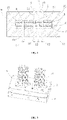
- the first positioning assembly 11- the first section; 12- the second section; 13- the plastic part; 2- the second positioning assembly; 21- the third section; 22- the fourth section; 3- the third positioning assembly; 31- the fifth section; 32- the sixth section; 4- the fourth positioning assembly; 5- the armour clamp main body on the first layer; 6- the armour clamp main body on the second layer; 7- the armour clamp main body on the third layer; 8-the body; 81-the insertion part; 9-the plate body assembly; 91-the first plate body; 92-the second plate body; 10-ejector rob.
- install In the description of the present utility model, it should be noted that, unless otherwise explicitly specified or limited, the terms “install”, “link” and “connect” are to be construed broadly, and may be, for example, fixedly connect, detachably connect, or integrally connect; may be mechanically or electrically connect; they may be connected directly or indirectly through intervening media, or they may be interconnected between two elements.
- install In the description of the present utility model, it should be noted that, unless otherwise explicitly specified or limited, the terms “install”, “link” and “connect” are to be construed broadly, and may be, for example, fixedly connect, detachably connect, or integrally connect; may be mechanically or electrically connect; they may be connected directly or indirectly through intervening media, or they may be interconnected between two elements.
- link In the description of the present utility model, it should be noted that, unless otherwise explicitly specified or limited, the terms “install”, “link” and “connect” are to be construed broadly, and may be, for example, fixedly
- the present invention provides an armour clamp positioning mechanism for positioning an armour clamp, wherein the armour clamp positioning mechanism is arranged in a mold, so as to facilitate direct injection molding after the armour clamp is positioned.
- the mold is provided with a first plate body and a second plate body, wherein the first plate body is an upper mold plate of the mold, the second plate body is a lower mold plate of the mold, and the positioning assembly is arranged on the first plate body and the second plate body.
- the armour clamp comprises at least two layers of armour clamp main bodies arranged at intervals; further comprising: at least three positioning assemblies, comprising a first positioning assembly 1, a second positioning assembly 2, and a third positioning assembly 3; wherein, the first positioning assembly 1 comprises a first section 11 and a second section 12; the first section 11 is arranged to penetrate through the armour clamp main body 5 on the first layer and abut against a top wall of the armour clamp main body 6 on the second layer, and the second section 12 is arranged to abut against a bottom wall of the armour clamp main body 6 on the second layer; the second positioning assembly 2 comprises a third section 21 and a fourth section 22; the third section 21 is arranged to abut against a top wall of the armour clamp main body 5 on the first layer, and the fourth section 22 is arranged to penetrate through the armour clamp main body 6 on the second layer and abut against a bottom wall of the armour clamp main body 5 on the first layer; and the third positioning assembly 3 is arranged to penetrate through the armour clamp
- the armour clamp main body on each layer is C-shaped, when positioning the armour clamp main body 5 on the first layer and the armour clamp main body 6 on the second layer, the armour clamp main bodies on the two layers can be enclosed to form an annular structure, and then positioning is carried out.
- the armour clamp main bodies on the two layers are arranged at intervals along the vertical direction, and a plastic part 13 is injection molded outside the armour clamp main body 5 on the first layer and the armour clamp main body 6 on the second layer.
- a positioning hole is arranged on the armour clamp main body, when positioning, the first section 11 of the first positioning assembly 1 penetrates through the armour clamp main body 5 on the first layer from top to bottom, and the end of the first section 11 is arranged to abut against the top wall of the armour clamp main body 6 on the second layer for positioning and fixing; then, the second section 12 is is arranged to abut against the bottom wall of the armour clamp main body 6 on the second layer; then, the end of the third section 21 of the second positioning assembly 2 is arranged to abut against the top wall of the armour clamp main body 5 on the first layer, then the fourth section 22 is arranged to penetrate through the armour clamp main body 6 on the second layer from bottom to top, and the end of the fourth section 22 is arranged to abut against the bottom wall of the armour clamp main body 5 on the first layer for positioning and fixing; finally, a third positioning assembly 3 is arranged to penetrate through the armour clamp main body 5 on the first layer and the armour clamp main body 6 on the second layer together,
- first section 11 and the second section 12 are located on the same axis, and the third section 21 and the fourth section 22 are located on the same axis, the coaxiality of the armour clamp main body 5 on the first layer and the armour clamp main body 6 on the second layer after being positioned is ensured, so that the positioning precision is ensured, and the positioning deviation is avoided.
- a plurality of positioning assemblies may be arranged at intervals along a circumferential direction of the armour clamp main bodies; therefore, the armour clamp main body can be positioned in all directions of the armour clamp main body, so that the positioning precision and the positioning stability are ensured.
- the three positioning assemblies are in the form of cylinder; specifically, the cylinder comprises a body 8 arranged on a plate body assembly; an insertion part 81 arranged at one end of the body 8 far away from the plate body assembly, and the insertion part 81 has a diameter less than that of the body 8; setting the diameter of the insertion part 81 to be smaller than the diameter of the body 8 can ensure that the cylinder can be smoothly inserted into the positioning hole of the armour clamp main body, meanwhile, a gap is also left for the cylinder to be inserted into the armour clamp main body to avoid scratching between the insertion part of the cylinder and the positioning hole of the armour clamp main body, so as to avoid the armour powder on the armour clamp main body of being scraped off.
- the end of the insertion part 81 is arranged with a chamfer, firstly, the burrs at the end of the insertion part are removed, making the cylinder more beautiful, and meanwhile, it is also convenient for the insertion part to be quickly inserted into the positioning hole of the armour clamp body.
- the armour clamp positioning mechanism comprises four positioning assemblies
- the third positioning assembly 3 comprises a fifth section 31 and a sixth section 32
- the fifth section 31 is arranged to abut against the top wall of the armour clamp main body 5 on the first layer
- the sixth section 32 is arranged to penetrate through the armour clamp main body 6 on the second layer and the armour clamp main body 7 on the third layer and abut against the bottom wall of the armour clamp main body 5 on the first layer
- a fourth positioning assembly 4 is arranged to penetrate through the armour clamp main body 5 on the first layer, the armour clamp main body 6 on the second layer and the armour clamp main body 7 on the third layer.
- the first section 1 of the first positioning assembly 11 is arranged to penetrate through the armour clamp main body 5 on the first layer and the armour clamp main body 6 on the second layer from top to bottom, and the end of the first section 11 is arranged to abut against the top wall of the armour clamp main body 7 on the third layer; then, the second section 12 is is arranged to abut against the bottom wall of the armour clamp main body 7 on the third layer; then, the end of the third section 21 of the second positioning assembly 2 is arranged to penetrate through the armour clamp main body 5 on the first layer, and abut against the top wall of the armour clamp main body 6 on the second layer, then the fourth section 22 is arranged to penetrate through the armour clamp main body 7 on the third layer from bottom to top, and the end of the fourth section 22 is arranged to abut against the bottom wall of the armour clamp main body 6 on the second layer; then, the end of the fifth section 31 of the third positioning assembly 3 is arranged
- the armour clamp main body 5 on the first layer, the armour clamp main body 6 on the second layer and the armour clamp main body 7 on the third layer are arranged with a plurality of clamping parts (not shown in the figure), these clamping parts are used to clamp the connecting line to position the connecting line.
- the present invention also provides an injection mold, which comprises the armour clamp positioning mechanism; when it is used, firstly, the armour clamp is positioned by the positioning mechanism, and after being positioned, the armour clamp positioning mechanism is mounted in a plastic mold to perform an injection molding process, but the clamping parts of the armour clamp does not need to be inj ected.
- the injection mold futher comprises a plate body assembly 9;
- the plate body assembly 9 comprises a first plate body 91 and a second plate body 92;
- the first plate body 91 is an upper mold plate of the mold,
- the second plate body 92 is a lower mold plate of the mold, and the positioning assembly is arranged on the first plate body 91 and the second plate body 92.
- the first section 11, the third section 21 and the fifth section 31 are fixed on the first plate body 91 and are fixedly connected with the first plate body 91, so that the first section 11, the third section 21 and the fifth section 31 are fixed conveniently and are also convenient to use.
- the second section 12, the fourth section 22 and the sixth section 32 are fixed on the second plate body 92 and are fixedly connected with the second plate body 92, so that the second section 12, the fourth section 22 and the sixth section 32 are fixed conveniently and are also convenient to use. Meanwhile, the ejector rod 10 is arranged on the injection mold, and after the armour clamp is positioned, the armour clamp is ejected out, so that the injection molding of the armour clamp main body 5 on the first layer, the armour clamp main body 6 on the second layer and the armour clamp main body 7 on the third layer is completed, and the armour clamp is formed.
- the armour clamp has three layers of armour clamp main bodies
- the first section 1 of the first positioning assembly 11 is arranged to penetrate through the armour clamp main body 5 on the first layer and the armour clamp main body 6 on the second layer from top to bottom, and the end of the first section 11 is arranged to abut against the top wall of the armour clamp main body 7 on the third layer
- the second section 12 is arranged to abut against the bottom wall of the armour clamp main body 7 on the third layer
- the end of the third section 21 of the second positioning assembly 2 is arranged to penetrate through the armour clamp main body 5 on the first layer, and abut against the top wall of the armour clamp main body 6 on the second layer
- the fourth section 22 is arranged to penetrate through the armour clamp main body 7 on the third layer from bottom to top, and the end of the fourth section 22 is arranged to abut against the bottom wall of the armour clamp main body 6 on the second layer
- the fourth section 22 is arranged to penetrate through the armour clamp main body 7 on the third layer
Landscapes
- Engineering & Computer Science (AREA)
- Manufacturing & Machinery (AREA)
- Mechanical Engineering (AREA)
- Moulds For Moulding Plastics Or The Like (AREA)
- Injection Moulding Of Plastics Or The Like (AREA)
Applications Claiming Priority (1)
| Application Number | Priority Date | Filing Date | Title |
|---|---|---|---|
| CN202110163388.7A CN112936731A (zh) | 2021-02-05 | 2021-02-05 | 一种金具定位机构及注塑模具 |
Publications (1)
| Publication Number | Publication Date |
|---|---|
| EP4040652A1 true EP4040652A1 (de) | 2022-08-10 |
Family
ID=76242726
Family Applications (1)
| Application Number | Title | Priority Date | Filing Date |
|---|---|---|---|
| EP21186167.9A Pending EP4040652A1 (de) | 2021-02-05 | 2021-07-16 | Mechanismus zur positionierung und spritzgussform |
Country Status (3)
| Country | Link |
|---|---|
| EP (1) | EP4040652A1 (de) |
| JP (1) | JP7184973B2 (de) |
| CN (1) | CN112936731A (de) |
Citations (2)
| Publication number | Priority date | Publication date | Assignee | Title |
|---|---|---|---|---|
| EP2139098A2 (de) * | 2008-06-27 | 2009-12-30 | Sugiyama Seisakusho Co., LTD. | Anschlussklemmenvorrichtung für einen bürstenlosen Motor und dessen Einsatzformverfahren |
| US20150263580A1 (en) * | 2013-03-08 | 2015-09-17 | Kayaba Industry Co., Ltd. | Bus bar unit |
Family Cites Families (5)
| Publication number | Priority date | Publication date | Assignee | Title |
|---|---|---|---|---|
| JP5060758B2 (ja) * | 2006-10-11 | 2012-10-31 | ハジメ産業株式会社 | 金型装置、インサート成形品及びインサート成形方法 |
| WO2011118226A1 (ja) * | 2010-03-26 | 2011-09-29 | 三菱重工プラスチックテクノロジー株式会社 | 繊維強化複合材の製造方法 |
| JP6731788B2 (ja) * | 2016-06-02 | 2020-07-29 | 株式会社Subaru | 繊維強化複合材料の製造方法 |
| JP2018065263A (ja) * | 2016-10-17 | 2018-04-26 | アルプス電気株式会社 | 複合成形体の製造方法および複合成形体 |
| JP6822381B2 (ja) * | 2017-11-06 | 2021-01-27 | 株式会社デンソー | 通電部材モジュール、及びその製造方法 |
-
2021
- 2021-02-05 CN CN202110163388.7A patent/CN112936731A/zh active Pending
- 2021-07-16 EP EP21186167.9A patent/EP4040652A1/de active Pending
- 2021-07-20 JP JP2021119363A patent/JP7184973B2/ja active Active
Patent Citations (2)
| Publication number | Priority date | Publication date | Assignee | Title |
|---|---|---|---|---|
| EP2139098A2 (de) * | 2008-06-27 | 2009-12-30 | Sugiyama Seisakusho Co., LTD. | Anschlussklemmenvorrichtung für einen bürstenlosen Motor und dessen Einsatzformverfahren |
| US20150263580A1 (en) * | 2013-03-08 | 2015-09-17 | Kayaba Industry Co., Ltd. | Bus bar unit |
Also Published As
| Publication number | Publication date |
|---|---|
| CN112936731A (zh) | 2021-06-11 |
| JP7184973B2 (ja) | 2022-12-06 |
| JP2022120769A (ja) | 2022-08-18 |
Similar Documents
| Publication | Publication Date | Title |
|---|---|---|
| US8378214B2 (en) | Harness connection member | |
| US20060113101A1 (en) | Coaxial cable with angle connector | |
| US9641052B2 (en) | Connector of vehicular angled connector-integrated servo motor and production method thereof | |
| US20160149385A1 (en) | Electric wire protection member | |
| EP4040652A1 (de) | Mechanismus zur positionierung und spritzgussform | |
| CN106252956A (zh) | 电连接器 | |
| CN210576644U (zh) | 一种单声道音频插头及其铆压式插头连接件 | |
| CN218632549U (zh) | 连接器定位结构 | |
| CN212097229U (zh) | 一种预注塑一射产品及包胶注塑二射产品 | |
| CN209948142U (zh) | 一种密封式端子模组及连接器 | |
| CN212968149U (zh) | 一种复杂端子内模件结构及连接端子 | |
| CN210744203U (zh) | 储能连接器 | |
| CN111037844A (zh) | 一种预注塑一射产品及包胶注塑二射产品 | |
| CN217507745U (zh) | 一种连接器及具有其的电机 | |
| CN115579674B (zh) | 一种注塑成型的电极连接器及其制作方法 | |
| CN221783501U (zh) | 一种防水电连接器 | |
| CN220219419U (zh) | 半成品固定组合结构及注塑模具装置 | |
| CN219427333U (zh) | 嵌件注塑的模具 | |
| CN218242352U (zh) | 多pin磁吸插头连接器 | |
| CN220836418U (zh) | 注胶夹具和电缆模组加工工装 | |
| CN111146618A (zh) | 一种复杂端子内模件结构及连接端子 | |
| EP4075617A1 (de) | Haltevorrichtung und verfahren zum halten | |
| CN210607694U (zh) | 通讯连接器 | |
| CN216400442U (zh) | 一种用于多斜度产品的模具斜抽芯结构 | |
| CN212498663U (zh) | 嵌入件及具有该嵌入件的成型件 |
Legal Events
| Date | Code | Title | Description |
|---|---|---|---|
| PUAI | Public reference made under article 153(3) epc to a published international application that has entered the european phase |
Free format text: ORIGINAL CODE: 0009012 |
|
| STAA | Information on the status of an ep patent application or granted ep patent |
Free format text: STATUS: REQUEST FOR EXAMINATION WAS MADE |
|
| 17P | Request for examination filed |
Effective date: 20210716 |
|
| AK | Designated contracting states |
Kind code of ref document: A1 Designated state(s): AL AT BE BG CH CY CZ DE DK EE ES FI FR GB GR HR HU IE IS IT LI LT LU LV MC MK MT NL NO PL PT RO RS SE SI SK SM TR |
|
| STAA | Information on the status of an ep patent application or granted ep patent |
Free format text: STATUS: EXAMINATION IS IN PROGRESS |
|
| 17Q | First examination report despatched |
Effective date: 20250710 |