EP4036331A2 - Rabat pour un dispositif de fermeture anti-odeurs et/ou dispositif anti-retour, ainsi que dispositif de fermeture anti-odeurs doté d'un tel rabat - Google Patents
Rabat pour un dispositif de fermeture anti-odeurs et/ou dispositif anti-retour, ainsi que dispositif de fermeture anti-odeurs doté d'un tel rabat Download PDFInfo
- Publication number
- EP4036331A2 EP4036331A2 EP22153982.8A EP22153982A EP4036331A2 EP 4036331 A2 EP4036331 A2 EP 4036331A2 EP 22153982 A EP22153982 A EP 22153982A EP 4036331 A2 EP4036331 A2 EP 4036331A2
- Authority
- EP
- European Patent Office
- Prior art keywords
- flap
- odor trap
- trap device
- drain
- housing
- Prior art date
- Legal status (The legal status is an assumption and is not a legal conclusion. Google has not performed a legal analysis and makes no representation as to the accuracy of the status listed.)
- Pending
Links
Images


Classifications
-
- E—FIXED CONSTRUCTIONS
- E03—WATER SUPPLY; SEWERAGE
- E03F—SEWERS; CESSPOOLS
- E03F5/00—Sewerage structures
- E03F5/04—Gullies inlets, road sinks, floor drains with or without odour seals or sediment traps
- E03F5/042—Arrangements of means against overflow of water, backing-up from the drain
-
- E—FIXED CONSTRUCTIONS
- E03—WATER SUPPLY; SEWERAGE
- E03C—DOMESTIC PLUMBING INSTALLATIONS FOR FRESH WATER OR WASTE WATER; SINKS
- E03C1/00—Domestic plumbing installations for fresh water or waste water; Sinks
- E03C1/12—Plumbing installations for waste water; Basins or fountains connected thereto; Sinks
- E03C1/28—Odour seals
- E03C1/284—Odour seals having U-shaped trap
- E03C1/288—Odour seals having U-shaped trap having non-return valves against return of waste water
-
- E—FIXED CONSTRUCTIONS
- E03—WATER SUPPLY; SEWERAGE
- E03F—SEWERS; CESSPOOLS
- E03F5/00—Sewerage structures
- E03F5/04—Gullies inlets, road sinks, floor drains with or without odour seals or sediment traps
- E03F5/0407—Floor drains for indoor use
-
- E—FIXED CONSTRUCTIONS
- E03—WATER SUPPLY; SEWERAGE
- E03F—SEWERS; CESSPOOLS
- E03F7/00—Other installations or implements for operating sewer systems, e.g. for preventing or indicating stoppage; Emptying cesspools
- E03F7/02—Shut-off devices
- E03F7/04—Valves for preventing return flow
-
- E—FIXED CONSTRUCTIONS
- E03—WATER SUPPLY; SEWERAGE
- E03F—SEWERS; CESSPOOLS
- E03F5/00—Sewerage structures
- E03F5/04—Gullies inlets, road sinks, floor drains with or without odour seals or sediment traps
- E03F2005/0416—Gullies inlets, road sinks, floor drains with or without odour seals or sediment traps with an odour seal
- E03F2005/0417—Gullies inlets, road sinks, floor drains with or without odour seals or sediment traps with an odour seal in the form of a valve
Definitions
- the present invention relates to a flap according to the preamble of claim 1, an odor trap device according to the preamble of claim 5, an odor trap device according to the preamble of claim 13 and a drain device according to the preamble of claim 15.
- a flap of the aforementioned type is from the WO 2010/089577 A1 known.
- the flap disclosed therein is arranged in an angled drain pipe, which serves as an odor trap device for a toilet.
- the flap is attached to one side of the drain socket and, in a first position, closes a drain opening of the toilet. It can be pivoted from the first position against the force of gravity into a second position. It can be held in the closed position by magnetic force, for which purpose a magnet is fitted in the flap and a ferromagnetic strip is fitted to the outlet connection piece.
- An odor trap device of the type mentioned is from US 2014/0053923 A1 known.
- the odor trap device disclosed therein comprises a cylindrical pipe socket with an inlet opening and an outlet opening and a flap which is pivotably held in the pipe socket.
- the flap can be pivoted about an axis running through the cylinder axis of the pipe socket. It can be held in the closed position on the edge of the pipe socket by magnetic force.
- the problem on which the present invention is based is the creation of a flap of the type mentioned at the beginning, which ensures a secure closure of the odor trap device or the backflow protection and/or can be produced inexpensively.
- the problem on which the present invention is based is also the creation of an odor trap device of the type mentioned at the outset that ensures a secure closure of the drain device and/or can be produced inexpensively and/or can enable a high water throughput despite a compact design.
- a drainage device with such an odor trap device is to be specified.
- the plastic of the flap is a magnetizable plastic.
- a magnetizable plastic can contain iron particles, for example.
- the use of a magnetizable plastic eliminates the need to attach a magnetizable part to the flap to enable the flap to be held magnetically in the closed position.
- the use of a magnetizable plastic ensures that the flap is more fail-safe because no magnetizable part attached to the flap can become detached from the flap.
- the work step of additionally attaching a magnetizable part is saved, so that overall the manufacturing costs of the flap can be reduced.
- the flap can be in the form of an injection molded part consisting of at least two components, with a first of the components being a magnetizable plastic and with a second of the components being a plastic which is non-magnetizable and non-magnetic.
- the second component can preferably serve as a seal, in particular with the second component being designed as a sealing lip.
- a further plastic can be used in addition to the magnetizable or magnetic plastic, which can, for example, fulfill the function of a sealing lip.
- the second component consists of a more flexible or less brittle material than the first component, in particular with the part of the flap formed by the second component being set up to contribute to the pivotability of the flap, preferably to form a hinge .
- the closure part consists at least partially of a magnetizable plastic and that a magnet is arranged on the housing in at least one area adjacent to the closure part in the closed state or at least one area of the housing adjacent to the closure part in the closed state a magnetic material.
- the magnetic material is a magnetic metal or a magnetic plastic.
- a magnetizable plastic for the closure part and/or a magnetic plastic for the housing eliminates the need to attach a magnetizable part to the closure part or a magnet to the housing. This ensures greater reliability of the housing.
- the production costs of the closure part and/or the production costs of the housing can be reduced, so that the odor trap device can be produced more cost-effectively overall.
- the closure part is a flap which can be pivoted from a first position, in which the drain opening is closed by the flap, into a second position, in which the drain opening is open, in particular the flap being a flap according to the invention .
- the magnetic holding force in the closed position is reinforced by the weight of the flap, so that the flap is held even more securely in the closed position.
- this increases the amount of water that flows between the inlet opening and the flap in the closed position can be present in the housing without forcing the flap out of the closed position.
- the odor trap device is set up in such a way that the flap is pivoted from the first position into the second position by the weight and/or the pressure of the water in the housing.
- a large opening can be quickly created by moving the flap out of the closed position, which opening can enable a high water throughput.
- the housing prefferably be designed as an injection molded part consisting of at least two components, with one of the components serving as a seal, in particular as a molded seal, which is at least partially arranged in a region of the housing facing the flap.
- a further plastic can be used in addition to a magnetic plastic, which can, for example, fulfill the function of a sealing lip.
- the closure part can be a drain cup which can be moved from a first position, in which the drain opening is closed by the drain cup, into a second position, in which the drain opening is open.
- the housing can be at least partially surrounded by the drain cup.
- the odor trap device is set up in such a way that the drain cup is moved downwards from the first position into the second position by the weight of the water in the housing.
- the water level above which the drain opening is opened can be predetermined by the magnetic force and the arrangement of the at least one magnet or the at least one area made of a magnetic material.
- the housing and/or the drain cup can have guide elements which ensure that the drain cup is guided during a movement from the first to the second position and/or from the second to the first position. A reliably reproducible back and forth movement of the drain cup between the first and the second position is made possible again by such guide elements.
- the side wall is partially hollow sphere-shaped at least in sections, the side wall being partially hollow sphere-shaped at least in sections over more than half of its extension from the inlet opening to the outlet opening, in particular over more than two thirds of its extension from the inlet opening to the outlet opening is.
- the at least partially hollow-spherical design of the side wall results in a particularly effective flow inside the housing, so that the odor trap device can enable a high water throughput despite its compact design.
- the side wall in the region adjacent to the inlet opening is partially hollow-spherical, at least in sections.
- the effective flow can ideally be in an area adjacent to the inlet opening begin directly at the inlet opening and continue to the vicinity of the outlet opening, ideally to the outlet opening.
- the flap is a flap according to the invention and/or that the odor trap device is a odor trap device according to the invention.
- the odor trap device can not only enable a high water throughput, but also ensure a secure closure of the drain device and can be produced inexpensively.
- the odor trap device is set up to serve as a backflow protection. As a result, the odor trap device is more versatile.
- the odor trap device can be set up to be connected to the drain device via a bayonet lock. This can result in an easy-to-manufacture but nevertheless secure attachment of the odor trap device, which can prevent the odor trap device from being pushed out of the drain device even in the event of strong back pressure.
- the odor trap device is an odor trap device according to the invention. Accordingly, the odor trap device and the drain device can comprise parts of a bayonet catch that can be connected to one another.
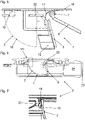
- the in the Figures 1 to 5 depicted odor trap device 1 comprises a housing 2 with an inlet opening 3 and a Drain opening 4 (see 2 ).
- the housing 2 also includes a seal 5 which, in the exemplary embodiment shown, is designed as a sealing lip surrounding the outlet opening 4 .
- the seal 5 can be molded onto the housing 2, for example.
- the housing 2 can be designed as an injection molded part consisting of two components.
- the odor trap device 1 also includes a flap 6 serving as a closure part, which is attached pivotably to the upper side of the outlet opening 4 .
- the pivotable attachment of the flap 6 takes place in particular via a hinge 7, which is formed by a hinge rod 8 and corresponding receptacles 9, 10 on the housing 2 and the flap 6 (see FIG 2 and figure 5 ).
- the flap 6 is from a first position (see for example 1 and 6 ), in which the flap 6 bears against the seal 5 and closes the outlet opening 4, can be pivoted into a second position in which the flap 6 releases the outlet opening 4 (see in particular figure 5 ).
- a first position water in the housing 2 cannot drain away, whereas in the second position, the waste water in the housing 2 can exit through the outlet opening 4 .
- the flap 6 can therefore exercise a valve function.
- the odor trap device 1 also includes a top cover 11, which is designed as a grating in the illustrated embodiment (see 1 and 2 ). It is entirely possible to provide a differently designed top cover or to omit the top cover 11 .
- the inlet opening 3 is surrounded by a peripheral upper edge 18 of the housing 2 (see FIG 3 ) on which the top cover 11 rests.
- the odor trap device 1 further comprises two pockets 12, 13 on the housing 2, in which magnets 14, 15 are introduced (see 2 and 4 ).
- the pockets 12 , 13 are arranged in such a way that the magnets 14 , 15 face the flap 6 below the seal 5 .
- the flap 6 In order to hold the flap 6 in the first position, the flap 6 consists of a magnetizable plastic, at least in the areas opposite the magnets 14, 15. The plastic of the flap 6 can therefore contain iron particles, for example. In the first position, the flap 6 is attracted by the magnets 14, 15 and pressed against the seal 5.
- At least one area of the housing 2 adjacent to the flap 6 in the closed state consists of a magnetic material.
- This magnetic material can be metal or plastic.
- at least one area of the housing 2 that is adjacent to the flap 6 in the closed state can consist of a magnetic plastic.
- the seal 5 is not arranged on the housing 2 but on the flap 6 .
- the seal 5 is molded onto the flap 6 .
- the flap 6 can be designed as an injection molded part consisting of two components, with a first component being a magnetizable plastic, whereas the second component is the plastic from which the seal is made.
- the second component can consist of a more flexible or less brittle material than the first component.
- the housing 2 has a side wall 16 which extends from the inlet opening 3 to the outlet opening 4 and which is designed at least partially in the form of a partially hollow sphere (see FIG 3 and figure 5 ).
- the side wall 16 is designed in the form of a partially hollow sphere, in particular in the area adjacent to the inlet opening 3 .
- the side wall 16 is at least partially hollow spherical over more than half of its extension from the inlet opening 3 to the outlet opening 4, in particular over more than two thirds of its extension, preferably almost over the entire extension, from the inlet opening 3 to the outlet opening 4.
- the at least partially hollow spherical design of the side wall 16 results in a particularly effective flow inside the housing 2, so that the odor trap device 1 can enable a high water throughput despite its compact design.
- a rounded inlet surface 17 is provided on the upper side of the housing 2, which is arranged partially above the flap 6 and, starting from the upper edge 18, extends radially inwards and a little way down into the housing 2 extends to the drain opening 4 (see 3 and figure 5 ).
- odor trap device 1 On the outside of the housing 2 are parts 19, 20 of a bayonet lock, which will be explained in more detail below, via which the odor trap device 1 with an in 6 illustrated drainage device 21 can be connected.
- the drain device 21 comprises an inlet opening 22 and a drain opening 23, which is formed on a drain connector 24 (see 6 ).
- a drain connector 24 see 6 .
- water collecting means are arranged above the drain device 21, which are designed, for example, as a channel.
- the odor trap device 1 is arranged in the drain device 21 in such a way that water that has entered through the inlet opening 22 of the drain device 21 can enter the inlet opening 3 of the odor trap device 1 . Furthermore, water that has escaped from the drain opening 4 of the odor trap device 1 can pass through the drain connector 24 to the drain opening 23 of the drain device 21 and exit through this from the drain device 21 .
- the odor trap device 1 can be inserted into the drain device 21 and connected to it via the bayonet lock. The connection is made by pushing in from above and slightly twisting the odor trap device 1 within the drain device 21
- the drain device 21 has parts 25 of the bayonet lock which can interact with the parts 19, 20 of the housing 2.
- a part 25 of the bayonet catch arranged on the drain device 21 can be in a connected position of the drain device 21 and
- the odor trap device 1 can be arranged between the upper edge 18 and the part 19 of the housing 1 (see 7 ).
- the bayonet lock results in a secure attachment of the odor trap device 1 in the drain device 21.
- the odor trap device 1 can therefore also fulfill the function of a backflow protection, because even with strong back pressure from a drain pipe connected to the drain connector 24, the odor trap device 1 can be pushed out of the drain device 21 is prevented by the bayonet lock.
- the flap 6 is pressed against the housing 2 or the seal 5 by a corresponding back pressure, so that no water can flow upwards through the odor trap device 1 and out of the drain device 21 .
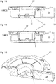
- the odor trap device 1 shown also comprises a housing 2 with an inlet opening 3 and an outlet opening 4 (see for example 8 and 10 ).
- the housing 2 also includes a seal 5 which, in the exemplary embodiment shown, is designed as a sealing lip surrounding the outlet opening 4 .
- the seal 5 can be molded onto the housing 2, for example.
- the housing 2 can be designed as an injection molded part consisting of two components.
- the odor trap device 1 also includes a drain cup 26 serving as a closure part, into which the housing 2 protrudes.
- the drain cup 26 has an essentially cylindrical cross-section with a bottom 27 and a side wall 28 which extends upwards from the bottom and is designed as a cylinder jacket surface.
- the drain cup 26 When the housing 2 projects down to the bottom 27 of the drain cup 26 and the seal 5 rests on the bottom 27 of the drain cup 26, the drain cup 26 is in the first, closed position (see, for example, Fig 9 ). When the housing 2 terminates above the bottom 27 of the drain cup 26, the drain cup 26 is in the second, open position (see e.g 10 ). In this position, water can enter the drain cup 26 through the outlet opening 4 and exit the drain cup 26 over the upper edge of the side wall 28 .
- the odor trap device 1 according to Figures 8 to 12 further comprises two pockets 12, 13 on the housing 2, in which magnets 14, 15 are introduced (see 8 ).
- the seal 5 closes the pockets 12, 13 at the bottom.
- the pockets 12, 13 are therefore arranged on the underside of the housing 2 such that only the comparatively thin seal 5 is arranged between the magnets 14, 15 and the bottom 27 of the drain cup 26 in the first, closed position.
- the drain cup 26 In order to keep the drain cup 26 in the first position, the drain cup 26 consists of a magnetizable plastic, at least in the areas opposite the magnets 14, 15.
- the plastic of the drain cup 26 can therefore contain iron particles, for example.
- the drain cup 26 is attracted by the magnets 14, 15 and pressed against the seal 5 in the first position.
- the attraction of the magnets 14, 15 can move the drain cup 26 back into the first position. This movement can be supported by an optional spring.
- the drain cup 26 has two opposite guide grooves 29, into which correspondingly shaped guide sections 30 of the housing 2 engage (see FIG 8 and 12 ).
- a recess 31 extending at least partially in a vertical direction when in use is provided in the guide sections 30, in which a nose 32 attached to the guide grooves 29 engages in order to limit the movement of the drain cup 26 in the vertical direction.
- At least one area of the housing 2 adjacent to the drain cup 26 in the closed state consists of a magnetic material.
- This magnetic material can be metal or plastic.
- at least one area of the housing 2 that is adjacent to the drainage cup 26 in the closed state can consist of a magnetic plastic.
- the seal 5 is not arranged on the housing 2 but on the drain cup 26 .
- the seal 5 is molded onto the drain cup 26 .
- the drain cup 26 can be designed as an injection molded part consisting of two components, with a first component being a magnetizable plastic, whereas the second component is the plastic from which the seal is made.
- the second component being made of a more flexible or less brittle material than the first component.
- the second embodiment of a drain device 21 illustrated also comprises an inlet opening 22 and a drain opening 23 which is formed on a drain connector 24 .
- water collecting means are arranged above the drain device 21, which are designed, for example, as a channel.
- the second embodiment of the odor trap device 1 is arranged such that water that has entered through the inlet opening 22 of the drain device 21 can enter the inlet opening 3 of the odor trap device 1 . Furthermore, water that has escaped over the upper edge of the side wall 28 of the drainage cup 26 can reach the drainage opening 23 of the drainage device 21 through the drainage connection piece 24 and exit through this from the drainage device 21 .
- the odor trap device 1 can be inserted into the drain device 21 .
- the second embodiment of the odor trap device 1 can also be connected to the second embodiment of the drain device 21 via a bayonet lock.
- the connection can also be done by pushing in from above and slightly twisting the odor trap device 1 within the drain device 21 .
- the bayonet lock results in a secure attachment of the odor trap device 1 in the drain device 21. Therefore, the odor trap device 1 can also have the function of a Fulfill backwater protection, because even with a strong backpressure from a drain pipe connected to the drain pipe 24, the odor trap device 1 is prevented from being pushed out of the drain device 21 by the bayonet lock. At the same time, the drain cup 26 is pressed against the housing 2 or the seal 5 by a corresponding back pressure, so that no water can flow upwards through the odor trap device 1 and out of the drain device 21 .
Landscapes
- Engineering & Computer Science (AREA)
- Health & Medical Sciences (AREA)
- Life Sciences & Earth Sciences (AREA)
- Hydrology & Water Resources (AREA)
- Public Health (AREA)
- Water Supply & Treatment (AREA)
- Environmental & Geological Engineering (AREA)
- Sink And Installation For Waste Water (AREA)
Priority Applications (1)
| Application Number | Priority Date | Filing Date | Title |
|---|---|---|---|
| EP23180875.9A EP4239138A3 (fr) | 2021-01-29 | 2022-01-28 | Clapet pour un dispositif de fermeture anti-odeurs et/ou anti-refoulement ainsi que dispositif de fermeture anti-odeurs doté d'un tel clapet |
Applications Claiming Priority (1)
| Application Number | Priority Date | Filing Date | Title |
|---|---|---|---|
| DE102021102052.2A DE102021102052A1 (de) | 2021-01-29 | 2021-01-29 | Klappe für eine Geruchsverschlussvorrichtung und/oder eine Rückstausicherung sowie Geruchsverschlussvorrichtung mit einer derartigen Klappe |
Related Child Applications (1)
| Application Number | Title | Priority Date | Filing Date |
|---|---|---|---|
| EP23180875.9A Division EP4239138A3 (fr) | 2021-01-29 | 2022-01-28 | Clapet pour un dispositif de fermeture anti-odeurs et/ou anti-refoulement ainsi que dispositif de fermeture anti-odeurs doté d'un tel clapet |
Publications (2)
| Publication Number | Publication Date |
|---|---|
| EP4036331A2 true EP4036331A2 (fr) | 2022-08-03 |
| EP4036331A3 EP4036331A3 (fr) | 2022-12-14 |
Family
ID=80218548
Family Applications (2)
| Application Number | Title | Priority Date | Filing Date |
|---|---|---|---|
| EP23180875.9A Withdrawn EP4239138A3 (fr) | 2021-01-29 | 2022-01-28 | Clapet pour un dispositif de fermeture anti-odeurs et/ou anti-refoulement ainsi que dispositif de fermeture anti-odeurs doté d'un tel clapet |
| EP22153982.8A Pending EP4036331A3 (fr) | 2021-01-29 | 2022-01-28 | Rabat pour un dispositif de fermeture anti-odeurs et/ou dispositif anti-retour, ainsi que dispositif de fermeture anti-odeurs doté d'un tel rabat |
Family Applications Before (1)
| Application Number | Title | Priority Date | Filing Date |
|---|---|---|---|
| EP23180875.9A Withdrawn EP4239138A3 (fr) | 2021-01-29 | 2022-01-28 | Clapet pour un dispositif de fermeture anti-odeurs et/ou anti-refoulement ainsi que dispositif de fermeture anti-odeurs doté d'un tel clapet |
Country Status (2)
| Country | Link |
|---|---|
| EP (2) | EP4239138A3 (fr) |
| DE (2) | DE102021102052A1 (fr) |
Families Citing this family (2)
| Publication number | Priority date | Publication date | Assignee | Title |
|---|---|---|---|---|
| US20240344309A1 (en) * | 2023-04-13 | 2024-10-17 | Zurn Water, Llc | Trap seal protection device |
| EP4506517A1 (fr) | 2023-08-07 | 2025-02-12 | Hauraton GmbH & Co. KG | Dispositif de fermeture pour une gouttiere |
Citations (4)
| Publication number | Priority date | Publication date | Assignee | Title |
|---|---|---|---|---|
| DE2401899A1 (de) * | 1974-01-16 | 1975-07-24 | Horst Manfred Schierling | Dachgully |
| DE10231086A1 (de) * | 2002-04-09 | 2003-10-30 | Draebing Kg Wegu | Vorrichtung zur Zwangsentlüftung eines Innenraums eines Kraftfahrzeugs |
| WO2010089577A1 (fr) | 2009-02-06 | 2010-08-12 | Albert Cozens | Adaptateur de clapet anti-retour pour toilettes |
| US20140053923A1 (en) | 2012-08-27 | 2014-02-27 | The Rectorseal Corporation | Apparatus and Methods for Limiting or Preventing Backflow of Gas up Through a Plumbing Fixture |
Family Cites Families (9)
| Publication number | Priority date | Publication date | Assignee | Title |
|---|---|---|---|---|
| DE6928773U (de) * | 1969-07-18 | 1969-12-04 | Fritz Fortenbacher | Magnetisch haftende platte aus gummi- oder kunststoffgebundenem dauermagnetwerkstoff |
| DE4309219C2 (de) | 1993-03-23 | 2003-03-06 | Kessel Gmbh | Bodenablauf |
| KR200385876Y1 (ko) * | 2005-03-07 | 2005-06-03 | 주식회사 리텍 | 욕실바닥용 봉수트랩의 개선구조 |
| DE102006008077B3 (de) * | 2006-02-22 | 2007-04-12 | Barlog Plastics Gmbh | Verfahren zur Herstellung von Kunststoffteilen mit lackierter Oberfläche |
| KR101113539B1 (ko) * | 2010-08-13 | 2012-02-29 | 이유수 | 하수구 악취방지 장치 |
| CN202164678U (zh) | 2011-05-31 | 2012-03-14 | 张宏彬 | 一种全封闭侧排防臭易清洗地漏 |
| DE102012100835B4 (de) | 2012-02-01 | 2015-07-09 | Aco Severin Ahlmann Gmbh & Co. Kg | Glockengeruchsverschluss |
| CN106759806A (zh) * | 2016-12-22 | 2017-05-31 | 苏州七巧板日用品科技有限公司 | 一种组合式防臭地漏芯 |
| CN108842899A (zh) | 2018-08-20 | 2018-11-20 | 赵崇武 | 隔臭地漏排水芯 |
-
2021
- 2021-01-29 DE DE102021102052.2A patent/DE102021102052A1/de active Pending
-
2022
- 2022-01-28 EP EP23180875.9A patent/EP4239138A3/fr not_active Withdrawn
- 2022-01-28 EP EP22153982.8A patent/EP4036331A3/fr active Pending
- 2022-01-28 DE DE202022100495.1U patent/DE202022100495U1/de active Active
Patent Citations (4)
| Publication number | Priority date | Publication date | Assignee | Title |
|---|---|---|---|---|
| DE2401899A1 (de) * | 1974-01-16 | 1975-07-24 | Horst Manfred Schierling | Dachgully |
| DE10231086A1 (de) * | 2002-04-09 | 2003-10-30 | Draebing Kg Wegu | Vorrichtung zur Zwangsentlüftung eines Innenraums eines Kraftfahrzeugs |
| WO2010089577A1 (fr) | 2009-02-06 | 2010-08-12 | Albert Cozens | Adaptateur de clapet anti-retour pour toilettes |
| US20140053923A1 (en) | 2012-08-27 | 2014-02-27 | The Rectorseal Corporation | Apparatus and Methods for Limiting or Preventing Backflow of Gas up Through a Plumbing Fixture |
Also Published As
| Publication number | Publication date |
|---|---|
| DE102021102052A1 (de) | 2022-08-04 |
| EP4036331A3 (fr) | 2022-12-14 |
| DE202022100495U1 (de) | 2022-02-17 |
| EP4239138A2 (fr) | 2023-09-06 |
| EP4239138A3 (fr) | 2023-11-29 |
Similar Documents
| Publication | Publication Date | Title |
|---|---|---|
| EP4036331A2 (fr) | Rabat pour un dispositif de fermeture anti-odeurs et/ou dispositif anti-retour, ainsi que dispositif de fermeture anti-odeurs doté d'un tel rabat | |
| DE202009010367U1 (de) | Vorrichtung zur Trennung von Regenwasser von chemisch, biologisch und/oder toxisch belasteten Abwässern | |
| DE69124729T2 (de) | Wasser-Verschluss | |
| EP1866487B1 (fr) | Dispositif de retenue pour un regard d'egout | |
| EP1188870A2 (fr) | Siphon pour un urinoir | |
| EP3751067B1 (fr) | Système de dimensionnement de tuyaux | |
| DE102005009777B4 (de) | Rückstauverschluss | |
| EP3578723B1 (fr) | Fermeture anti-odeurs pour une évacuation d'eau ainsi qu'une évacuation d'eau pourvue d'une telle fermeture anti-odeurs | |
| DE1658198B1 (de) | Sinkkasten | |
| DE69214775T2 (de) | Zwischenphase-Vakuumventil | |
| DE202008011255U1 (de) | Systemtrenner II | |
| DE102009009707B4 (de) | Entwässerungsvorrichtung | |
| DE102004063015A1 (de) | Kraftstofffilter | |
| EP1548193A2 (fr) | Dispositif pour empêcher l'eau d'entrer dans un puit de regard | |
| DE102005016526B3 (de) | Absperrvorrichtung für einen Abwasserkontrollschacht | |
| DE8129236U1 (de) | Ventilsitzorgan | |
| EP4102000A1 (fr) | Entrée de sol dotée de siphon | |
| AT407652B (de) | Bausatz zur bildung eines wassergeruchsverschlusses | |
| EP4568767B1 (fr) | Dispositif et procédé de filtration de liquides, en particulier dans des vannes de remplissage | |
| DE102010001906B4 (de) | Selbsttätig arbeitende Verschlussvorrichtung und Leichtflüssigkeitsabscheider mit einer selbsttätig arbeitenden Verschlussvorrichtung | |
| DE10240906B4 (de) | Kanalschacht für Abwasser-Kanalisation | |
| EP3945177A1 (fr) | Dispositif d'évacuation d'eau | |
| EP4624684A1 (fr) | Fermeture à reflux vertical avec guide de poussoir de soupape blindé côté sortie | |
| WO1999060221A1 (fr) | Dispositif pour introduire un liquide par a-coups dans un systeme de canalisation | |
| DE102022132098A1 (de) | Vorrichtung und Verfahren zur Filterung von Flüssigkeiten, insbesondere in Füllventilen |
Legal Events
| Date | Code | Title | Description |
|---|---|---|---|
| PUAI | Public reference made under article 153(3) epc to a published international application that has entered the european phase |
Free format text: ORIGINAL CODE: 0009012 |
|
| STAA | Information on the status of an ep patent application or granted ep patent |
Free format text: STATUS: THE APPLICATION HAS BEEN PUBLISHED |
|
| AK | Designated contracting states |
Kind code of ref document: A2 Designated state(s): AL AT BE BG CH CY CZ DE DK EE ES FI FR GB GR HR HU IE IS IT LI LT LU LV MC MK MT NL NO PL PT RO RS SE SI SK SM TR |
|
| PUAL | Search report despatched |
Free format text: ORIGINAL CODE: 0009013 |
|
| AK | Designated contracting states |
Kind code of ref document: A3 Designated state(s): AL AT BE BG CH CY CZ DE DK EE ES FI FR GB GR HR HU IE IS IT LI LT LU LV MC MK MT NL NO PL PT RO RS SE SI SK SM TR |
|
| RIC1 | Information provided on ipc code assigned before grant |
Ipc: E03F 7/04 20060101ALI20221110BHEP Ipc: E03C 1/288 20060101AFI20221110BHEP |
|
| STAA | Information on the status of an ep patent application or granted ep patent |
Free format text: STATUS: REQUEST FOR EXAMINATION WAS MADE |
|
| 17P | Request for examination filed |
Effective date: 20230614 |
|
| RBV | Designated contracting states (corrected) |
Designated state(s): AL AT BE BG CH CY CZ DE DK EE ES FI FR GB GR HR HU IE IS IT LI LT LU LV MC MK MT NL NO PL PT RO RS SE SI SK SM TR |
|
| STAA | Information on the status of an ep patent application or granted ep patent |
Free format text: STATUS: EXAMINATION IS IN PROGRESS |
|
| 17Q | First examination report despatched |
Effective date: 20250403 |