EP4036331A2 - Flap for an odour seal device and / or anti-backflow device, as well as an odour seal device with such a flap - Google Patents
Flap for an odour seal device and / or anti-backflow device, as well as an odour seal device with such a flap Download PDFInfo
- Publication number
- EP4036331A2 EP4036331A2 EP22153982.8A EP22153982A EP4036331A2 EP 4036331 A2 EP4036331 A2 EP 4036331A2 EP 22153982 A EP22153982 A EP 22153982A EP 4036331 A2 EP4036331 A2 EP 4036331A2
- Authority
- EP
- European Patent Office
- Prior art keywords
- flap
- odor trap
- trap device
- drain
- housing
- Prior art date
- Legal status (The legal status is an assumption and is not a legal conclusion. Google has not performed a legal analysis and makes no representation as to the accuracy of the status listed.)
- Pending
Links
Images


Classifications
-
- E—FIXED CONSTRUCTIONS
- E03—WATER SUPPLY; SEWERAGE
- E03F—SEWERS; CESSPOOLS
- E03F5/00—Sewerage structures
- E03F5/04—Gullies inlets, road sinks, floor drains with or without odour seals or sediment traps
- E03F5/042—Arrangements of means against overflow of water, backing-up from the drain
-
- E—FIXED CONSTRUCTIONS
- E03—WATER SUPPLY; SEWERAGE
- E03C—DOMESTIC PLUMBING INSTALLATIONS FOR FRESH WATER OR WASTE WATER; SINKS
- E03C1/00—Domestic plumbing installations for fresh water or waste water; Sinks
- E03C1/12—Plumbing installations for waste water; Basins or fountains connected thereto; Sinks
- E03C1/28—Odour seals
- E03C1/284—Odour seals having U-shaped trap
- E03C1/288—Odour seals having U-shaped trap having non-return valves against return of waste water
-
- E—FIXED CONSTRUCTIONS
- E03—WATER SUPPLY; SEWERAGE
- E03F—SEWERS; CESSPOOLS
- E03F5/00—Sewerage structures
- E03F5/04—Gullies inlets, road sinks, floor drains with or without odour seals or sediment traps
- E03F5/0407—Floor drains for indoor use
-
- E—FIXED CONSTRUCTIONS
- E03—WATER SUPPLY; SEWERAGE
- E03F—SEWERS; CESSPOOLS
- E03F7/00—Other installations or implements for operating sewer systems, e.g. for preventing or indicating stoppage; Emptying cesspools
- E03F7/02—Shut-off devices
- E03F7/04—Valves for preventing return flow
-
- E—FIXED CONSTRUCTIONS
- E03—WATER SUPPLY; SEWERAGE
- E03F—SEWERS; CESSPOOLS
- E03F5/00—Sewerage structures
- E03F5/04—Gullies inlets, road sinks, floor drains with or without odour seals or sediment traps
- E03F2005/0416—Gullies inlets, road sinks, floor drains with or without odour seals or sediment traps with an odour seal
- E03F2005/0417—Gullies inlets, road sinks, floor drains with or without odour seals or sediment traps with an odour seal in the form of a valve
Definitions
- the present invention relates to a flap according to the preamble of claim 1, an odor trap device according to the preamble of claim 5, an odor trap device according to the preamble of claim 13 and a drain device according to the preamble of claim 15.
- a flap of the aforementioned type is from the WO 2010/089577 A1 known.
- the flap disclosed therein is arranged in an angled drain pipe, which serves as an odor trap device for a toilet.
- the flap is attached to one side of the drain socket and, in a first position, closes a drain opening of the toilet. It can be pivoted from the first position against the force of gravity into a second position. It can be held in the closed position by magnetic force, for which purpose a magnet is fitted in the flap and a ferromagnetic strip is fitted to the outlet connection piece.
- An odor trap device of the type mentioned is from US 2014/0053923 A1 known.
- the odor trap device disclosed therein comprises a cylindrical pipe socket with an inlet opening and an outlet opening and a flap which is pivotably held in the pipe socket.
- the flap can be pivoted about an axis running through the cylinder axis of the pipe socket. It can be held in the closed position on the edge of the pipe socket by magnetic force.
- the problem on which the present invention is based is the creation of a flap of the type mentioned at the beginning, which ensures a secure closure of the odor trap device or the backflow protection and/or can be produced inexpensively.
- the problem on which the present invention is based is also the creation of an odor trap device of the type mentioned at the outset that ensures a secure closure of the drain device and/or can be produced inexpensively and/or can enable a high water throughput despite a compact design.
- a drainage device with such an odor trap device is to be specified.
- the plastic of the flap is a magnetizable plastic.
- a magnetizable plastic can contain iron particles, for example.
- the use of a magnetizable plastic eliminates the need to attach a magnetizable part to the flap to enable the flap to be held magnetically in the closed position.
- the use of a magnetizable plastic ensures that the flap is more fail-safe because no magnetizable part attached to the flap can become detached from the flap.
- the work step of additionally attaching a magnetizable part is saved, so that overall the manufacturing costs of the flap can be reduced.
- the flap can be in the form of an injection molded part consisting of at least two components, with a first of the components being a magnetizable plastic and with a second of the components being a plastic which is non-magnetizable and non-magnetic.
- the second component can preferably serve as a seal, in particular with the second component being designed as a sealing lip.
- a further plastic can be used in addition to the magnetizable or magnetic plastic, which can, for example, fulfill the function of a sealing lip.
- the second component consists of a more flexible or less brittle material than the first component, in particular with the part of the flap formed by the second component being set up to contribute to the pivotability of the flap, preferably to form a hinge .
- the closure part consists at least partially of a magnetizable plastic and that a magnet is arranged on the housing in at least one area adjacent to the closure part in the closed state or at least one area of the housing adjacent to the closure part in the closed state a magnetic material.
- the magnetic material is a magnetic metal or a magnetic plastic.
- a magnetizable plastic for the closure part and/or a magnetic plastic for the housing eliminates the need to attach a magnetizable part to the closure part or a magnet to the housing. This ensures greater reliability of the housing.
- the production costs of the closure part and/or the production costs of the housing can be reduced, so that the odor trap device can be produced more cost-effectively overall.
- the closure part is a flap which can be pivoted from a first position, in which the drain opening is closed by the flap, into a second position, in which the drain opening is open, in particular the flap being a flap according to the invention .
- the magnetic holding force in the closed position is reinforced by the weight of the flap, so that the flap is held even more securely in the closed position.
- this increases the amount of water that flows between the inlet opening and the flap in the closed position can be present in the housing without forcing the flap out of the closed position.
- the odor trap device is set up in such a way that the flap is pivoted from the first position into the second position by the weight and/or the pressure of the water in the housing.
- a large opening can be quickly created by moving the flap out of the closed position, which opening can enable a high water throughput.
- the housing prefferably be designed as an injection molded part consisting of at least two components, with one of the components serving as a seal, in particular as a molded seal, which is at least partially arranged in a region of the housing facing the flap.
- a further plastic can be used in addition to a magnetic plastic, which can, for example, fulfill the function of a sealing lip.
- the closure part can be a drain cup which can be moved from a first position, in which the drain opening is closed by the drain cup, into a second position, in which the drain opening is open.
- the housing can be at least partially surrounded by the drain cup.
- the odor trap device is set up in such a way that the drain cup is moved downwards from the first position into the second position by the weight of the water in the housing.
- the water level above which the drain opening is opened can be predetermined by the magnetic force and the arrangement of the at least one magnet or the at least one area made of a magnetic material.
- the housing and/or the drain cup can have guide elements which ensure that the drain cup is guided during a movement from the first to the second position and/or from the second to the first position. A reliably reproducible back and forth movement of the drain cup between the first and the second position is made possible again by such guide elements.
- the side wall is partially hollow sphere-shaped at least in sections, the side wall being partially hollow sphere-shaped at least in sections over more than half of its extension from the inlet opening to the outlet opening, in particular over more than two thirds of its extension from the inlet opening to the outlet opening is.
- the at least partially hollow-spherical design of the side wall results in a particularly effective flow inside the housing, so that the odor trap device can enable a high water throughput despite its compact design.
- the side wall in the region adjacent to the inlet opening is partially hollow-spherical, at least in sections.
- the effective flow can ideally be in an area adjacent to the inlet opening begin directly at the inlet opening and continue to the vicinity of the outlet opening, ideally to the outlet opening.
- the flap is a flap according to the invention and/or that the odor trap device is a odor trap device according to the invention.
- the odor trap device can not only enable a high water throughput, but also ensure a secure closure of the drain device and can be produced inexpensively.
- the odor trap device is set up to serve as a backflow protection. As a result, the odor trap device is more versatile.
- the odor trap device can be set up to be connected to the drain device via a bayonet lock. This can result in an easy-to-manufacture but nevertheless secure attachment of the odor trap device, which can prevent the odor trap device from being pushed out of the drain device even in the event of strong back pressure.
- the odor trap device is an odor trap device according to the invention. Accordingly, the odor trap device and the drain device can comprise parts of a bayonet catch that can be connected to one another.
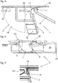
- the in the Figures 1 to 5 depicted odor trap device 1 comprises a housing 2 with an inlet opening 3 and a Drain opening 4 (see 2 ).
- the housing 2 also includes a seal 5 which, in the exemplary embodiment shown, is designed as a sealing lip surrounding the outlet opening 4 .
- the seal 5 can be molded onto the housing 2, for example.
- the housing 2 can be designed as an injection molded part consisting of two components.
- the odor trap device 1 also includes a flap 6 serving as a closure part, which is attached pivotably to the upper side of the outlet opening 4 .
- the pivotable attachment of the flap 6 takes place in particular via a hinge 7, which is formed by a hinge rod 8 and corresponding receptacles 9, 10 on the housing 2 and the flap 6 (see FIG 2 and figure 5 ).
- the flap 6 is from a first position (see for example 1 and 6 ), in which the flap 6 bears against the seal 5 and closes the outlet opening 4, can be pivoted into a second position in which the flap 6 releases the outlet opening 4 (see in particular figure 5 ).
- a first position water in the housing 2 cannot drain away, whereas in the second position, the waste water in the housing 2 can exit through the outlet opening 4 .
- the flap 6 can therefore exercise a valve function.
- the odor trap device 1 also includes a top cover 11, which is designed as a grating in the illustrated embodiment (see 1 and 2 ). It is entirely possible to provide a differently designed top cover or to omit the top cover 11 .
- the inlet opening 3 is surrounded by a peripheral upper edge 18 of the housing 2 (see FIG 3 ) on which the top cover 11 rests.
- the odor trap device 1 further comprises two pockets 12, 13 on the housing 2, in which magnets 14, 15 are introduced (see 2 and 4 ).
- the pockets 12 , 13 are arranged in such a way that the magnets 14 , 15 face the flap 6 below the seal 5 .
- the flap 6 In order to hold the flap 6 in the first position, the flap 6 consists of a magnetizable plastic, at least in the areas opposite the magnets 14, 15. The plastic of the flap 6 can therefore contain iron particles, for example. In the first position, the flap 6 is attracted by the magnets 14, 15 and pressed against the seal 5.
- At least one area of the housing 2 adjacent to the flap 6 in the closed state consists of a magnetic material.
- This magnetic material can be metal or plastic.
- at least one area of the housing 2 that is adjacent to the flap 6 in the closed state can consist of a magnetic plastic.
- the seal 5 is not arranged on the housing 2 but on the flap 6 .
- the seal 5 is molded onto the flap 6 .
- the flap 6 can be designed as an injection molded part consisting of two components, with a first component being a magnetizable plastic, whereas the second component is the plastic from which the seal is made.
- the second component can consist of a more flexible or less brittle material than the first component.
- the housing 2 has a side wall 16 which extends from the inlet opening 3 to the outlet opening 4 and which is designed at least partially in the form of a partially hollow sphere (see FIG 3 and figure 5 ).
- the side wall 16 is designed in the form of a partially hollow sphere, in particular in the area adjacent to the inlet opening 3 .
- the side wall 16 is at least partially hollow spherical over more than half of its extension from the inlet opening 3 to the outlet opening 4, in particular over more than two thirds of its extension, preferably almost over the entire extension, from the inlet opening 3 to the outlet opening 4.
- the at least partially hollow spherical design of the side wall 16 results in a particularly effective flow inside the housing 2, so that the odor trap device 1 can enable a high water throughput despite its compact design.
- a rounded inlet surface 17 is provided on the upper side of the housing 2, which is arranged partially above the flap 6 and, starting from the upper edge 18, extends radially inwards and a little way down into the housing 2 extends to the drain opening 4 (see 3 and figure 5 ).
- odor trap device 1 On the outside of the housing 2 are parts 19, 20 of a bayonet lock, which will be explained in more detail below, via which the odor trap device 1 with an in 6 illustrated drainage device 21 can be connected.
- the drain device 21 comprises an inlet opening 22 and a drain opening 23, which is formed on a drain connector 24 (see 6 ).
- a drain connector 24 see 6 .
- water collecting means are arranged above the drain device 21, which are designed, for example, as a channel.
- the odor trap device 1 is arranged in the drain device 21 in such a way that water that has entered through the inlet opening 22 of the drain device 21 can enter the inlet opening 3 of the odor trap device 1 . Furthermore, water that has escaped from the drain opening 4 of the odor trap device 1 can pass through the drain connector 24 to the drain opening 23 of the drain device 21 and exit through this from the drain device 21 .
- the odor trap device 1 can be inserted into the drain device 21 and connected to it via the bayonet lock. The connection is made by pushing in from above and slightly twisting the odor trap device 1 within the drain device 21
- the drain device 21 has parts 25 of the bayonet lock which can interact with the parts 19, 20 of the housing 2.
- a part 25 of the bayonet catch arranged on the drain device 21 can be in a connected position of the drain device 21 and
- the odor trap device 1 can be arranged between the upper edge 18 and the part 19 of the housing 1 (see 7 ).
- the bayonet lock results in a secure attachment of the odor trap device 1 in the drain device 21.
- the odor trap device 1 can therefore also fulfill the function of a backflow protection, because even with strong back pressure from a drain pipe connected to the drain connector 24, the odor trap device 1 can be pushed out of the drain device 21 is prevented by the bayonet lock.
- the flap 6 is pressed against the housing 2 or the seal 5 by a corresponding back pressure, so that no water can flow upwards through the odor trap device 1 and out of the drain device 21 .
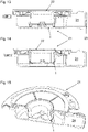
- the odor trap device 1 shown also comprises a housing 2 with an inlet opening 3 and an outlet opening 4 (see for example 8 and 10 ).
- the housing 2 also includes a seal 5 which, in the exemplary embodiment shown, is designed as a sealing lip surrounding the outlet opening 4 .
- the seal 5 can be molded onto the housing 2, for example.
- the housing 2 can be designed as an injection molded part consisting of two components.
- the odor trap device 1 also includes a drain cup 26 serving as a closure part, into which the housing 2 protrudes.
- the drain cup 26 has an essentially cylindrical cross-section with a bottom 27 and a side wall 28 which extends upwards from the bottom and is designed as a cylinder jacket surface.
- the drain cup 26 When the housing 2 projects down to the bottom 27 of the drain cup 26 and the seal 5 rests on the bottom 27 of the drain cup 26, the drain cup 26 is in the first, closed position (see, for example, Fig 9 ). When the housing 2 terminates above the bottom 27 of the drain cup 26, the drain cup 26 is in the second, open position (see e.g 10 ). In this position, water can enter the drain cup 26 through the outlet opening 4 and exit the drain cup 26 over the upper edge of the side wall 28 .
- the odor trap device 1 according to Figures 8 to 12 further comprises two pockets 12, 13 on the housing 2, in which magnets 14, 15 are introduced (see 8 ).
- the seal 5 closes the pockets 12, 13 at the bottom.
- the pockets 12, 13 are therefore arranged on the underside of the housing 2 such that only the comparatively thin seal 5 is arranged between the magnets 14, 15 and the bottom 27 of the drain cup 26 in the first, closed position.
- the drain cup 26 In order to keep the drain cup 26 in the first position, the drain cup 26 consists of a magnetizable plastic, at least in the areas opposite the magnets 14, 15.
- the plastic of the drain cup 26 can therefore contain iron particles, for example.
- the drain cup 26 is attracted by the magnets 14, 15 and pressed against the seal 5 in the first position.
- the attraction of the magnets 14, 15 can move the drain cup 26 back into the first position. This movement can be supported by an optional spring.
- the drain cup 26 has two opposite guide grooves 29, into which correspondingly shaped guide sections 30 of the housing 2 engage (see FIG 8 and 12 ).
- a recess 31 extending at least partially in a vertical direction when in use is provided in the guide sections 30, in which a nose 32 attached to the guide grooves 29 engages in order to limit the movement of the drain cup 26 in the vertical direction.
- At least one area of the housing 2 adjacent to the drain cup 26 in the closed state consists of a magnetic material.
- This magnetic material can be metal or plastic.
- at least one area of the housing 2 that is adjacent to the drainage cup 26 in the closed state can consist of a magnetic plastic.
- the seal 5 is not arranged on the housing 2 but on the drain cup 26 .
- the seal 5 is molded onto the drain cup 26 .
- the drain cup 26 can be designed as an injection molded part consisting of two components, with a first component being a magnetizable plastic, whereas the second component is the plastic from which the seal is made.
- the second component being made of a more flexible or less brittle material than the first component.
- the second embodiment of a drain device 21 illustrated also comprises an inlet opening 22 and a drain opening 23 which is formed on a drain connector 24 .
- water collecting means are arranged above the drain device 21, which are designed, for example, as a channel.
- the second embodiment of the odor trap device 1 is arranged such that water that has entered through the inlet opening 22 of the drain device 21 can enter the inlet opening 3 of the odor trap device 1 . Furthermore, water that has escaped over the upper edge of the side wall 28 of the drainage cup 26 can reach the drainage opening 23 of the drainage device 21 through the drainage connection piece 24 and exit through this from the drainage device 21 .
- the odor trap device 1 can be inserted into the drain device 21 .
- the second embodiment of the odor trap device 1 can also be connected to the second embodiment of the drain device 21 via a bayonet lock.
- the connection can also be done by pushing in from above and slightly twisting the odor trap device 1 within the drain device 21 .
- the bayonet lock results in a secure attachment of the odor trap device 1 in the drain device 21. Therefore, the odor trap device 1 can also have the function of a Fulfill backwater protection, because even with a strong backpressure from a drain pipe connected to the drain pipe 24, the odor trap device 1 is prevented from being pushed out of the drain device 21 by the bayonet lock. At the same time, the drain cup 26 is pressed against the housing 2 or the seal 5 by a corresponding back pressure, so that no water can flow upwards through the odor trap device 1 and out of the drain device 21 .
Landscapes
- Engineering & Computer Science (AREA)
- Health & Medical Sciences (AREA)
- Life Sciences & Earth Sciences (AREA)
- Hydrology & Water Resources (AREA)
- Public Health (AREA)
- Water Supply & Treatment (AREA)
- Environmental & Geological Engineering (AREA)
- Sink And Installation For Waste Water (AREA)
Abstract
Klappe (6) für eine Geruchsverschlussvorrichtung (1) und/oder eine Rückstausicherung, wobei die Klappe (6) dazu eingerichtet ist, in der Geruchsverschlussvorrichtung (1) und/oder in der Rückstausicherung als Ventilklappe verwendet zu werden und dabei zur Ausübung der Ventilfunktion verschwenkbar ist, wobei die Klappe (6) zumindest teilweise aus Kunststoff besteht, und wobei der Kunststoff der Klappe (6) ein magnetisierbarer Kunststoff ist. Die Erfindung betrifft weiterhin eine Geruchsverschlussvorrichtung 1 und eine Ablaufvorrichtung mit einer Geruchsverschlussvorrichtung 1.

Description
Die vorliegende Erfindung betrifft eine Klappe gemäß dem Oberbegriff des Anspruchs 1, eine Geruchsverschlussvorrichtung gemäß dem Oberbegriff des Anspruchs 5, eine Geruchsverschlussvorrichtung gemäß dem Oberbegriff des Anspruchs 13 sowie eine Ablaufvorrichtung gemäß dem Oberbegriff des Anspruchs 15.The present invention relates to a flap according to the preamble of
Eine Klappe der vorgenannten Art ist aus der
Eine Geruchsverschlussvorrichtung der eingangs genannten Art ist aus der
Das der vorliegenden Erfindung zugrundeliegende Problem ist die Schaffung einer Klappe der eingangs genannten Art, die einen sicheren Verschluss der Geruchsverschlussvorrichtung oder der Rückstausicherung gewährleistet und/oder kostengünstig herstellbar ist. Das der vorliegenden Erfindung zugrundeliegende Problem ist weiterhin die Schaffung einer Geruchsverschlussvorrichtung der eingangs genannten Art, die einen sicheren Verschluss der Ablaufvorrichtung gewährleistet und/oder kostengünstig herstellbar ist und/oder trotz eines kompakten Aufbaus einen hohen Wasserdurchsatz ermöglichen kann. Weiterhin soll eine Ablaufvorrichtung mit einer derartigen Geruchsverschlussvorrichtung angegeben werden.The problem on which the present invention is based is the creation of a flap of the type mentioned at the beginning, which ensures a secure closure of the odor trap device or the backflow protection and/or can be produced inexpensively. The problem on which the present invention is based is also the creation of an odor trap device of the type mentioned at the outset that ensures a secure closure of the drain device and/or can be produced inexpensively and/or can enable a high water throughput despite a compact design. Furthermore, a drainage device with such an odor trap device is to be specified.
Dies wird erfindungsgemäß durch eine Klappe der eingangs genannten Art mit den kennzeichnenden Merkmalen des Anspruchs 1, eine Geruchsverschlussvorrichtung der eingangs genannten Art mit den kennzeichnenden Merkmalen des Anspruchs 5 oder des Anspruchs 13 sowie durch eine Ablaufvorrichtung der eingangs genannten Art mit den kennzeichnenden Merkmalen des Anspruchs 15 erreicht. Die Unteransprüche betreffen bevorzugte Ausgestaltungen der Erfindung.According to the invention, this is achieved by a flap of the type mentioned at the outset having the characterizing features of
Gemäß Anspruch 1 ist vorgesehen, dass der Kunststoff der Klappe ein magnetisierbarer Kunststoff ist. Ein magnetisierbarer Kunststoff kann beispielsweise Eisenpartikel enthalten. Durch die Verwendung eines magnetisierbaren Kunststoffs entfällt die Notwendigkeit, ein magnetisierbares Teil an der Klappe anzubringen, um eine magnetische Halterung der Klappe in der Verschlussstellung zu ermöglichen. Durch die Verwendung eines magnetisierbaren Kunststoffs wird eine größere Ausfallsicherheit der Klappe gewährleistet, weil sich kein an der Klappe angebrachtes magnetisierbares Teil von der Klappe lösen kann. Weiterhin wird der Arbeitsschritt des zusätzlichen Anbringens eines magnetisierbaren Teils eingespart, so dass insgesamt die Herstellungskosten der Klappe gesenkt werden können.According to
Es kann vorgesehen sein, dass die Klappe als ein aus mindestens zwei Komponenten bestehendes Spritzgussteil ausgebildet ist, wobei eine erste der Komponenten ein magnetisierbarer Kunststoff ist und wobei eine zweite der Komponenten ein Kunststoff ist, der nicht magnetisierbar und nicht magnetisch ist. Vorzugsweise kann die zweite Komponente als Dichtung dienen, insbesondere wobei die zweite Komponente als Dichtlippe ausgebildet ist. Bei der Ausbildung der Klappe als ein aus mindestens zwei Komponenten bestehendes Spritzgussteil kann neben dem magnetisierbaren oder magnetischen Kunststoff ein weiterer Kunststoff verwendet werden, der beispielsweise die Funktion einer Dichtlippe erfüllen kann.Provision can be made for the flap to be in the form of an injection molded part consisting of at least two components, with a first of the components being a magnetizable plastic and with a second of the components being a plastic which is non-magnetizable and non-magnetic. The second component can preferably serve as a seal, in particular with the second component being designed as a sealing lip. In the design of the flap as an injection molded part consisting of at least two components, a further plastic can be used in addition to the magnetizable or magnetic plastic, which can, for example, fulfill the function of a sealing lip.
Alternativ oder zusätzlich kann vorgesehen sein, dass die zweite Komponente aus einem flexibleren oder weniger spröden Material als die erste Komponente besteht, insbesondere wobei der von der zweiten Komponente gebildete Teil der Klappe dazu eingerichtet ist, zur Verschwenkbarkeit der Klappe beizutragen, vorzugsweise ein Scharnier zu bilden.Alternatively or additionally, it can be provided that the second component consists of a more flexible or less brittle material than the first component, in particular with the part of the flap formed by the second component being set up to contribute to the pivotability of the flap, preferably to form a hinge .
Gemäß Anspruch 5 ist vorgesehen, dass das Verschlussteil zumindest teilweise aus einem magnetisierbaren Kunststoff besteht und dass an dem Gehäuse in mindestens einem im geschlossenen Zustand zu dem Verschlussteil benachbarten Bereich ein Magnet angeordnet ist oder mindestens ein im geschlossenen Zustand zu dem Verschlussteil benachbarter Bereich des Gehäuses aus einem magnetischen Material besteht. Dadurch kann eine sichere Halterung des Verschlussteils in der Verschlussstellung und damit ein sicherer Verschluss der Ablaufvorrichtung gewährleistet werden.According to
Dabei kann vorgesehen sein, dass das magnetische Material ein magnetisches Metall oder ein magnetischer Kunststoff ist. Insbesondere durch die Verwendung eines magnetisierbaren Kunststoffs für das Verschlussteil und/oder eines magnetischen Kunststoffs für das Gehäuse entfällt die Notwendigkeit, ein magnetisierbares Teil an dem Verschlussteil beziehungsweise einen Magneten an dem Gehäuse anzubringen. Dadurch wird eine größere Ausfallsicherheit des Gehäuses gewährleistet. Weiterhin können durch die Verwendung eines magnetisierbaren Kunststoffs für das Verschlussteil und/oder eines magnetischen Kunststoffs für das Gehäuse die Herstellungskosten des Verschlussteils und/oder die Herstellungskosten des Gehäuses gesenkt werden, so dass insgesamt die Geruchsverschlussvorrichtung kostengünstiger produziert werden kann.It can be provided that the magnetic material is a magnetic metal or a magnetic plastic. In particular, the use of a magnetizable plastic for the closure part and/or a magnetic plastic for the housing eliminates the need to attach a magnetizable part to the closure part or a magnet to the housing. This ensures greater reliability of the housing. Furthermore, by using a magnetizable plastic for the closure part and/or a magnetic plastic for the housing, the production costs of the closure part and/or the production costs of the housing can be reduced, so that the odor trap device can be produced more cost-effectively overall.
Es besteht die Möglichkeit, dass das Verschlussteil eine Klappe ist, die aus einer ersten Stellung, in der die Ablauföffnung von der Klappe verschlossen ist, in eine zweite Stellung verschwenkbar ist, in der die Ablauföffnung geöffnet ist, insbesondere wobei die Klappe eine erfindungsgemäße Klappe ist.There is the possibility that the closure part is a flap which can be pivoted from a first position, in which the drain opening is closed by the flap, into a second position, in which the drain opening is open, in particular the flap being a flap according to the invention .
Es kann vorgesehen sein, dass die Klappe so geneigt in der Geruchsverschlussvorrichtung angeordnet ist, dass das Verschwenken aus der ersten in die zweite Stellung gegen die Schwerkraft erfolgt. Dadurch wird die magnetische Haltekraft in der Verschlussstellung durch die Gewichtskraft der Klappe verstärkt, so dass die Halterung der Klappe in der Verschlussstellung noch sicherer wird. Weiterhin wird dadurch die Wassermenge erhöht, die in der Verschlussstellung zwischen der Einlauföffnung und der Klappe in dem Gehäuse vorhanden sein kann, ohne die Klappe aus der Verschlussstellung herauszudrücken.Provision can be made for the flap to be arranged in the odor trap device at such an incline that pivoting from the first to the second position takes place against the force of gravity. As a result, the magnetic holding force in the closed position is reinforced by the weight of the flap, so that the flap is held even more securely in the closed position. Furthermore, this increases the amount of water that flows between the inlet opening and the flap in the closed position can be present in the housing without forcing the flap out of the closed position.
Es besteht die Möglichkeit, dass die Geruchsverschlussvorrichtung dazu eingerichtet ist, dass die Klappe durch das Gewicht und/oder den Druck des in dem Gehäuse befindlichen Wassers aus der ersten Stellung in die zweite Stellung verschwenkt wird.There is the possibility that the odor trap device is set up in such a way that the flap is pivoted from the first position into the second position by the weight and/or the pressure of the water in the housing.
Es kann vorgesehen sein, dass die Klappe einseitig mit einem randseitigen Abschnitt an dem Gehäuse angebracht ist, insbesondere so, dass sie um ein in diesem Anbringungsbereich ausgebildetes Scharnier verschwenkbar ist. Bei einer derartigen Gestaltung kann durch eine Bewegung der Klappe aus der Verschlussstellung heraus schnell eine große Öffnung geschaffen werden, die einen hohen Wasserdurchsatz ermöglichen kann.Provision can be made for the flap to be attached to the housing on one side with an edge section, in particular in such a way that it can be pivoted about a hinge formed in this attachment area. With such a configuration, a large opening can be quickly created by moving the flap out of the closed position, which opening can enable a high water throughput.
Es besteht die Möglichkeit, dass das Gehäuse als ein aus mindestens zwei Komponenten bestehendes Spritzgussteil ausgebildet ist, wobei eine der Komponenten als Dichtung, insbesondere als angespritzte Dichtung, dient, die zumindest teilweise in einem der Klappe zugewandten Bereich des Gehäuses angeordnet ist. Auch bei der Ausbildung des Gehäuses als ein aus mindestens zwei Komponenten bestehendes Spritzgussteil kann neben einem magnetischen Kunststoff ein weiterer Kunststoff verwendet werden, der beispielsweise die Funktion einer Dichtlippe erfüllen kann.It is possible for the housing to be designed as an injection molded part consisting of at least two components, with one of the components serving as a seal, in particular as a molded seal, which is at least partially arranged in a region of the housing facing the flap. When the housing is designed as an injection molded part consisting of at least two components, a further plastic can be used in addition to a magnetic plastic, which can, for example, fulfill the function of a sealing lip.
Es kann vorgesehen sein, dass das Verschlussteil ein Ablaufbecher ist, der aus einer ersten Stellung, in der die Ablauföffnung von dem Ablaufbecher verschlossen ist, in eine zweite Stellung bewegbar ist, in der die Ablauföffnung geöffnet ist. Dabei kann das Gehäuse von dem Ablaufbecher zumindest teilweise umgeben sein.Provision can be made for the closure part to be a drain cup which can be moved from a first position, in which the drain opening is closed by the drain cup, into a second position, in which the drain opening is open. The housing can be at least partially surrounded by the drain cup.
Es besteht die Möglichkeit, dass die Geruchsverschlussvorrichtung dazu eingerichtet ist, dass der Ablaufbecher durch das Gewicht des in dem Gehäuse befindlichen Wassers aus der ersten Stellung nach unten in die zweite Stellung bewegt wird. Dabei kann durch die Magnetkraft und die Anordnung des mindestens einen Magnets oder des mindestens einen Bereichs aus einem magnetischen Material die Wasserhöhe vorgegeben werden, ab der die Ablauföffnung geöffnet wird.There is the possibility that the odor trap device is set up in such a way that the drain cup is moved downwards from the first position into the second position by the weight of the water in the housing. The water level above which the drain opening is opened can be predetermined by the magnetic force and the arrangement of the at least one magnet or the at least one area made of a magnetic material.
Das Gehäuse und/oder der Ablaufbecher können Führungselemente aufweisen, die eine Führung des Ablaufbechers bei einer Bewegung von der ersten in die zweite Stellung und/oder von der zweiten in die erste Stellung gewährleisten. Durch derartige Führungselemente wieder eine sicher reproduzierbare Hin- und Her-Bewegung des Ablaufbechers zwischen der ersten und der zweiten Stellung ermöglicht.The housing and/or the drain cup can have guide elements which ensure that the drain cup is guided during a movement from the first to the second position and/or from the second to the first position. A reliably reproducible back and forth movement of the drain cup between the first and the second position is made possible again by such guide elements.
Gemäß Anspruch 13 ist vorgesehen, dass die Seitenwand zumindest abschnittsweise teilhohlkugelförmig ausgebildet ist, wobei die Seitenwand über mehr als die Hälfte ihrer Erstreckung von der Einlauföffnung zu der Ablauföffnung, insbesondere über mehr als zwei Drittel ihrer Erstreckung von der Einlauföffnung zu der Ablauföffnung zumindest abschnittsweise teilhohlkugelförmig ausgebildet ist. Durch die zumindest abschnittsweise teilhohlkugelförmige Ausbildung der Seitenwand ergibt sich eine besonders effektive Strömung im Inneren des Gehäuses, so dass die Geruchsverschlussvorrichtung trotz eines kompakten Aufbaus einen hohen Wasserdurchsatz ermöglichen kann.According to
Es kann vorgesehen sein, dass die Seitenwand in dem zu der Einlauföffnung benachbarten Bereich zumindest abschnittsweise teilhohlkugelförmig ausgebildet ist. Damit kann die effektive Strömung in einem zu der Einlauföffnung benachbarten Bereich, idealerweise schon direkt an der Einlauföffnung, beginnen und sich bis in die Nähe der Ablauföffnung, idealerweise bis zur Ablauföffnung, fortsetzen.It can be provided that the side wall in the region adjacent to the inlet opening is partially hollow-spherical, at least in sections. In this way, the effective flow can ideally be in an area adjacent to the inlet opening begin directly at the inlet opening and continue to the vicinity of the outlet opening, ideally to the outlet opening.
Es besteht die Möglichkeit, dass die Klappe eine erfindungsgemäße Klappe ist und/oder dass die Geruchsverschlussvorrichtung eine erfindungsgemäße Geruchsverschlussvorrichtung ist. Dadurch kann die Geruchsverschlussvorrichtung nicht nur einen hohen Wasserdurchsatz ermöglichen, sondern auch einen sicheren Verschluss der Ablaufvorrichtung gewährleisten und kostengünstig herstellbar sein.There is the possibility that the flap is a flap according to the invention and/or that the odor trap device is a odor trap device according to the invention. As a result, the odor trap device can not only enable a high water throughput, but also ensure a secure closure of the drain device and can be produced inexpensively.
Es kann vorgesehen sein, dass die Geruchsverschlussvorrichtung dazu eingerichtet ist, als Rückstausicherung zu dienen. Dadurch ist die Geruchsverschlussvorrichtung vielseitiger einsetzbar.It can be provided that the odor trap device is set up to serve as a backflow protection. As a result, the odor trap device is more versatile.
Insbesondere für die Funktion der Rückstausicherung kann die Geruchsverschlussvorrichtung dazu eingerichtet sein, über einen Bajonettverschluss mit der Ablaufvorrichtung verbunden zu werden. Damit kann sich eine einfach herstellbare aber trotzdem sichere Befestigung der Geruchsverschlussvorrichtung ergeben, die auch bei starkem Rückstaudruck ein Herausdrücken der Geruchsverschlussvorrichtung aus der Ablaufvorrichtung verhindern kann.In particular for the function of backflow protection, the odor trap device can be set up to be connected to the drain device via a bayonet lock. This can result in an easy-to-manufacture but nevertheless secure attachment of the odor trap device, which can prevent the odor trap device from being pushed out of the drain device even in the event of strong back pressure.
Gemäß Anspruch 15 ist vorgesehen, dass die Geruchsverschlussvorrichtung eine erfindungsgemäße Geruchsverschlussvorrichtung ist. Dementsprechend können die Geruchsverschlussvorrichtung und die Ablaufvorrichtung miteinander verbindbare Teile eines Bajonettverschlusses umfassen.According to
Weitere Merkmale und Vorteile der vorliegenden Erfindung werden deutlich anhand der nachfolgenden Beschreibung bevorzugter Ausführungsbeispiele unter Bezugnahme auf die beiliegenden Abbildungen. Darin zeigen:
- Fig. 1
- eine perspektivische Ansicht einer ersten Ausführungsform einer erfindungsgemäßen Geruchsverschlussvorrichtung;
- Fig. 2
- eine Explosionsansicht der Geruchsverschlussvorrichtung gemäß
Fig. 1 ; - Fig. 3
- eine perspektivische Ansicht der Geruchsverschlussvorrichtung gemäß
Fig. 1 ohne obere Abdeckung; - Fig. 4
- eine weitere perspektivische Ansicht der Geruchsverschlussvorrichtung gemäß
Fig. 1 ohne obere Abdeckung und ohne Dichtung; - Fig. 5
- eine Seitenansicht der Geruchsverschlussvorrichtung gemäß
Fig. 1 ohne obere Abdeckung mit der Klappe in der zweiten, geöffneten Stellung; - Fig. 6
- eine Schnittansicht einer ersten Ausführungsform einer erfindungsgemäßen Ablaufvorrichtung mit der Klappe in der ersten, geschlossenen Stellung;
- Fig. 7
- ein Detail gemäß dem Pfeil VII in
Fig. 6 ; - Fig. 8
- eine Explosionsansicht einer zweiten Ausführungsform einer erfindungsgemäßen Geruchsverschlussvorrichtung;
- Fig. 9
- eine Schnittansicht der Geruchsverschlussvorrichtung gemäß
Fig. 8 mit dem Ablaufbecher in der ersten, geschlossenen Stellung; - Fig. 10
- eine Schnittansicht der Geruchsverschlussvorrichtung gemäß
Fig. 8 mit dem Ablaufbecher in der zweiten, geöffneten Stellung; - Fig. 11
- eine teilweise geschnittene perspektivische Ansicht der Geruchsverschlussvorrichtung gemäß
Fig. 8 mit dem Ablaufbecher in der zweiten, geöffneten Stellung; - Fig. 12
- eine teilweise geschnittene, gegenüber
Fig. 11 um 90° gedrehte perspektivische Ansicht der Geruchsverschlussvorrichtung gemäßFig. 8 mit dem Ablaufbecher in der zweiten, geöffneten Stellung; - Fig. 13
- eine Schnittansicht einer zweiten Ausführungsform einer erfindungsgemäßen Ablaufvorrichtung mit dem Ablaufbecher in der zweiten, geöffneten Stellung;
- Fig. 14
- eine Schnittansicht der Ablaufvorrichtung gemäß
Fig. 13 mit dem Ablaufbecher in der ersten, geschlossenen Stellung; - Fig. 15
- eine teilweise geschnittene perspektivische Ansicht der Ablaufvorrichtung gemäß
Fig. 13 mit dem Ablaufbecher in der ersten, geschlossenen Stellung.
- 1
- a perspective view of a first embodiment of a odor trap device according to the invention;
- 2
- an exploded view of the odor trap device according to FIG
1 ; - 3
- a perspective view of the odor trap device according to FIG
1 without top cover; - 4
- a further perspective view of the odor trap device according to FIG
1 without top cover and without seal; - figure 5
- a side view of the odor trap device according to FIG
1 without a top cover with the door in the second, open position; - 6
- a sectional view of a first embodiment of a drain device according to the invention with the flap in the first, closed position;
- 7
- a detail according to the arrow VII in
6 ; - 8
- an exploded view of a second embodiment of a odor trap device according to the invention;
- 9
- a sectional view of the odor trap device according to FIG
8 with the drain cup in the first, closed position; - 10
- a sectional view of the odor trap device according to FIG
8 with the drain cup in the second, open position; - 11
- a partially sectioned perspective view of the odor trap device according to FIG
8 with the drain cup in the second, open position; - 12
- a partially cut, opposite
11 90° rotated perspective view of the odor trap device according to FIG8 with the drain cup in the second, open position; - 13
- a sectional view of a second embodiment of a drain device according to the invention with the drain cup in the second, open position;
- 14
- a sectional view of the drain device according to FIG
13 with the drain cup in the first, closed position; - 15
- a partially sectioned perspective view of the drain device according to FIG
13 with the drain cup in the first, closed position.
In den Figuren sind gleiche und funktional gleiche Teile mit gleichen Bezugszeichen versehen.Identical and functionally identical parts are provided with the same reference symbols in the figures.
Die in den
Die Geruchsverschlussvorrichtung 1 umfasst weiterhin eine als Verschlussteil dienende Klappe 6, die schwenkbar an der Oberseite der Auslassöffnung 4 angebracht ist. Dabei erfolgt die schwenkbare Anbringung der Klappe 6 insbesondere über ein Scharnier 7, das durch eine Scharnierstange 8 und entsprechende Aufnahmen 9, 10 an dem Gehäuse 2 und der Klappe 6 gebildet wird (siehe
Die Klappe 6 ist aus einer ersten Stellung (siehe beispielsweise
Die Geruchsverschlussvorrichtung 1 umfasst weiterhin eine obere Abdeckung 11, die in dem abgebildeten Ausführungsbeispiel als Gitterrost ausgebildet ist (siehe
Die Geruchsverschlussvorrichtung 1 umfasst weiterhin zwei Taschen 12, 13 an dem Gehäuse 2, in die Magnete 14, 15 eingebracht sind (siehe
Um die Klappe 6 in der ersten Stellung zu halten, besteht die Klappe 6 zumindest in der den Magneten 14, 15 gegenüberliegenden Bereichen aus einem magnetisierbaren Kunststoff. Der Kunststoff der Klappe 6 kann also beispielsweise Eisenpartikel enthalten. Die Klappe 6 wird in der ersten Stellung von den Magneten 14, 15 angezogen und gegen die Dichtung 5 gedrückt.In order to hold the
Es besteht alternativ die Möglichkeit, dass an dem Gehäuse 2 keine Magnete 14, 15 in Taschen 12, 13 angeordnet sind, sondern dass mindestens ein im geschlossenen Zustand zu der Klappe 6 benachbarter Bereich des Gehäuses 2 aus einem magnetischen Material besteht. Dieses magnetische Material kann Metall oder Kunststoff sein. Beispielsweise kann mindestens ein im geschlossenen Zustand zu der Klappe 6 benachbarter Bereich des Gehäuses 2 aus einem magnetischen Kunststoff bestehen.Alternatively, there is the possibility that no
Es besteht weiterhin die Möglichkeit, dass die Dichtung 5 nicht an dem Gehäuse 2, sondern an der Klappe 6 angeordnet ist. In diesem Fall kann vorgesehen sein, dass die Dichtung 5 an die Klappe 6 angespritzt ist. Insbesondere kann dazu die Klappe 6 als aus zwei Komponenten bestehendes Spritzgussteil ausgebildet sein, wobei eine erste Komponente ein magnetisierbarer Kunststoff ist, wohingegen die zweite Komponente der Kunststoff ist, aus dem die Dichtung besteht. Beispielsweise kann dabei die zweite Komponente aus einem flexibleren oder weniger spröden Material bestehen als die erste Komponente.There is also the possibility that the
Das Gehäuse 2 weist eine sich von der Einlauföffnung 3 zu der Ablauföffnung 4 erstreckende Seitenwand 16 auf, die zumindest abschnittsweise teilhohlkugelförmig ausgebildet ist (siehe
Durch die zumindest abschnittsweise teilhohlkugelförmige Ausbildung der Seitenwand 16 ergibt sich eine besonders effektive Strömung im Inneren des Gehäuses 2, so dass die Geruchsverschlussvorrichtung 1 trotz eines kompakten Aufbaus einen hohen Wasserdurchsatz ermöglichen kann.The at least partially hollow spherical design of the
Im Bereich der Einlauföffnung 3 ist an der Oberseite des Gehäuses 2 eine abgerundete Einlauffläche 17 vorgesehen, die teilweise oberhalb der Klappe 6 angeordnet ist und sich ausgehend von dem oberen Rand 18 radial nach innen und dabei ein Stück weit nach unten in das Gehäuse 2 hinein bis zu der Ablauföffnung 4 erstreckt (siehe dazu
Damit wird die durch die teilhohlkugelförmige Seitenwand 16 bewirkte effektive Strömung unterstützt, so dass die Strömung in einem zu der Einlauföffnung 3 benachbarten Bereich, idealerweise schon direkt an der Einlauföffnung 3, beginnt und sich bis in die Nähe der Ablauföffnung 4, idealerweise bis zur Ablauföffnung 4, fortsetzt.This supports the effective flow caused by the partially hollow
An der Außenseite des Gehäuses 2 sind Teile 19, 20 eines im Nachfolgenden noch detaillierter erläuterten Bajonettverschlusses angeordnet, über den die Geruchsverschlussvorrichtung 1 mit einer in
Die Ablaufvorrichtung 21 umfasst eine Einlauföffnung 22 und eine Ablauföffnung 23, die an einem Ablaufstutzen 24 ausgebildet ist (siehe
In der Ablaufvorrichtung 21 ist die Geruchsverschlussvorrichtung 1 so angeordnet, dass durch die Einlauföffnung 22 der Ablaufvorrichtung 21 eingetretenes Wasser in die Einlauföffnung 3 Geruchsverschlussvorrichtung 1 eintreten kann. Weiterhin kann aus der Ablauföffnung 4 der Geruchsverschlussvorrichtung 1 ausgetretenes Wasser durch den Ablaufstutzen 24 zu der Ablauföffnung 23 der Ablaufvorrichtung 21 gelangen und durch diese aus der Ablaufvorrichtung 21 austreten.The
Die Geruchsverschlussvorrichtung 1 kann in die Ablaufvorrichtung 21 eingesetzt und über den Bajonettverschluss mit dieser verbunden werden. Die Verbindung geschieht dabei über ein Einschieben von oben und ein leichtes Verdrehen der Geruchsverschlussvorrichtung 1 innerhalb der Ablaufvorrichtung 21The
Dabei weist die Ablaufvorrichtung 21 Teile 25 des Bajonettverschlusses auf, die mit den Teilen 19, 20 des Gehäuses 2 zusammenwirken können. Insbesondere kann dabei ein an der Ablaufvorrichtung 21 angeordnetes Teil 25 des Bajonettverschlusses in einer verbundenen Stellung von Ablaufvorrichtung 21 und Geruchsverschlussvorrichtung 1 zwischen dem oberen Rand 18 und dem Teil 19 des Gehäuses 1 angeordnet sein (siehe
Durch den Bajonettverschluss ergibt sich eine sichere Befestigung der Geruchsverschlussvorrichtung 1 in der Ablaufvorrichtung 21. Daher kann die Geruchsverschlussvorrichtung 1 auch die Funktion einer Rückstausicherung erfüllen, weil auch bei einem starken Rückstaudruck aus einem mit dem Ablaufstutzen 24 verbundenen Ablaufrohr ein Herausdrücken der Geruchsverschlussvorrichtung 1 aus der Ablaufvorrichtung 21 durch den Bajonettverschluss verhindert wird. Gleichzeitig wird durch einen entsprechenden Rückstaudruck die Klappe 6 gegen das Gehäuse 2 beziehungsweise die Dichtung 5 gedrückt, so dass kein Wasser durch die Geruchsverschlussvorrichtung 1 nach oben aus der Ablaufvorrichtung 21 herausströmen kann.The bayonet lock results in a secure attachment of the
Die in den
Die Geruchsverschlussvorrichtung 1 umfasst weiterhin einen als Verschlussteil dienenden Ablaufbecher 26, in den das Gehäuse 2 hineinragt. Der Ablaufbecher 26 weist einen im wesentlichen zylindrischen Querschnitt mit einem Boden 27 und einer sich von diesem nach oben erstreckenden Seitenwand 28 auf, die als Zylindermantelfläche ausgebildet ist.The
Wenn das Gehäuse 2 nach unten bis zum Boden 27 des Ablaufbechers 26 ragt und die Dichtung 5 auf dem Boden 27 des Ablaufbechers 26 aufliegt, befindet sich der Ablaufbecher 26 in der ersten, geschlossenen Stellung (siehe beispielsweise
Die Geruchsverschlussvorrichtung 1 gemäß den
Um den Ablaufbecher 26 in der ersten Stellung zu halten, besteht der Ablaufbecher 26 zumindest in den Magneten 14, 15 gegenüberliegenden Bereichen aus einem magnetisierbaren Kunststoff. Der Kunststoff des Ablaufbechers 26 kann also beispielsweise Eisenpartikel enthalten. Der Ablaufbecher 26 wird in der ersten Stellung von den Magneten 14, 15 angezogen und gegen die Dichtung 5 gedrückt.In order to keep the
Wenn sich in dem Gehäuse 2 eine derartige Wassermenge befindet, dass die Gewichtskraft des Wassers größer als die magnetische Anziehungskraft ist, mit der der Boden 27 des Ablaufbechers 26 an die Magneten 14, 15 gezogen wird, wird der Ablaufbecher 26 nach unten in die zweite, geöffnete Stellung bewegt.If there is such an amount of water in the
Nach Abfluss des Wassers kann die Anziehungskraft der Magneten 14, 15 den Ablaufbecher 26 wieder in die erste Stellung bewegen. Diese Bewegung kann durch eine optionale Feder unterstützt werden.After the water has drained, the attraction of the
Der Ablaufbecher 26 weist für die Führung dieser Bewegung zwei einander gegenüberliegende Führungsnuten 29 auf, in die entsprechend geformte Führungsabschnitte 30 des Gehäuses 2 eingreifen (siehe
Es besteht alternativ die Möglichkeit, dass an dem Gehäuse 2 keine Magnete 14, 15 in Taschen 12, 13 angeordnet sind, sondern dass mindestens ein im geschlossenen Zustand zu dem Ablaufbecher 26 benachbarter Bereich des Gehäuses 2 aus einem magnetischen Material besteht. Dieses magnetische Material kann Metall oder Kunststoff sein. Beispielsweise kann mindestens ein im geschlossenen Zustand zu dem Ablaufbecher 26 benachbarter Bereich des Gehäuses 2 aus einem magnetischen Kunststoff bestehen.Alternatively, there is the possibility that no
Es besteht weiterhin die Möglichkeit, dass die Dichtung 5 nicht an dem Gehäuse 2, sondern an dem Ablaufbecher 26 angeordnet ist. In diesem Fall kann vorgesehen sein, dass die Dichtung 5 an den Ablaufbecher 26 angespritzt ist. Insbesondere kann dazu der Ablaufbecher 26 als aus zwei Komponenten bestehendes Spritzgussteil ausgebildet sein, wobei eine erste Komponente ein magnetisierbarer Kunststoff ist, wohingegen die zweite Komponente der Kunststoff ist, aus dem die Dichtung besteht. Beispielsweise kann dabei die zweite Komponente aus einem flexibleren oder weniger spröden Material bestehen als die erste Komponente.There is also the possibility that the
Die in den
In der zweiten Ausführungsform der Ablaufvorrichtung 21 ist die zweite Ausführungsform der Geruchsverschlussvorrichtung 1 so angeordnet, dass durch die Einlauföffnung 22 der Ablaufvorrichtung 21 eingetretenes Wasser in die Einlauföffnung 3 Geruchsverschlussvorrichtung 1 eintreten kann. Weiterhin kann über den oberen Rand der Seitenwand 28 des Ablaufbechers 26 ausgetretenes Wasser durch den Ablaufstutzen 24 zu der Ablauföffnung 23 der Ablaufvorrichtung 21 gelangen und durch diese aus der Ablaufvorrichtung 21 austreten.In the second embodiment of the
Die Geruchsverschlussvorrichtung 1 kann in die Ablaufvorrichtung 21 eingesetzt werden. Dabei besteht die Möglichkeit, dass auch die zweite Ausführungsform der Geruchsverschlussvorrichtung 1 über einen Bajonettverschluss mit der zweiten Ausführungsform der Ablaufvorrichtung 21 verbunden werden kann. Die Verbindung kann dabei ebenfalls über ein Einschieben von oben und ein leichtes Verdrehen der Geruchsverschlussvorrichtung 1 innerhalb der Ablaufvorrichtung 21 geschehen.The
Durch den Bajonettverschluss ergibt sich eine sichere Befestigung der Geruchsverschlussvorrichtung 1 in der Ablaufvorrichtung 21. Daher kann die Geruchsverschlussvorrichtung 1 auch die Funktion einer Rückstausicherung erfüllen, weil auch bei einem starken Rückstaudruck aus einem mit dem Ablaufstutzen 24 verbundenen Ablaufrohr ein Herausdrücken der Geruchsverschlussvorrichtung 1 aus der Ablaufvorrichtung 21 durch den Bajonettverschluss verhindert wird. Gleichzeitig wird durch einen entsprechenden Rückstaudruck der Ablaufbecher 26 gegen das Gehäuse 2 beziehungsweise die Dichtung 5 gedrückt, so dass kein Wasser durch die Geruchsverschlussvorrichtung 1 nach oben aus der Ablaufvorrichtung 21 herausströmen kann.The bayonet lock results in a secure attachment of the
Claims (15)
Priority Applications (1)
| Application Number | Priority Date | Filing Date | Title |
|---|---|---|---|
| EP23180875.9A EP4239138A3 (en) | 2021-01-29 | 2022-01-28 | Flap for an odour seal device and/or backflow prevention device and odour seal device with such a flap |
Applications Claiming Priority (1)
| Application Number | Priority Date | Filing Date | Title |
|---|---|---|---|
| DE102021102052.2A DE102021102052A1 (en) | 2021-01-29 | 2021-01-29 | Flap for an odor trap device and/or a backflow protection and odor trap device with such a flap |
Related Child Applications (1)
| Application Number | Title | Priority Date | Filing Date |
|---|---|---|---|
| EP23180875.9A Division EP4239138A3 (en) | 2021-01-29 | 2022-01-28 | Flap for an odour seal device and/or backflow prevention device and odour seal device with such a flap |
Publications (2)
| Publication Number | Publication Date |
|---|---|
| EP4036331A2 true EP4036331A2 (en) | 2022-08-03 |
| EP4036331A3 EP4036331A3 (en) | 2022-12-14 |
Family
ID=80218548
Family Applications (2)
| Application Number | Title | Priority Date | Filing Date |
|---|---|---|---|
| EP22153982.8A Pending EP4036331A3 (en) | 2021-01-29 | 2022-01-28 | Flap for an odour seal device and / or anti-backflow device, as well as an odour seal device with such a flap |
| EP23180875.9A Withdrawn EP4239138A3 (en) | 2021-01-29 | 2022-01-28 | Flap for an odour seal device and/or backflow prevention device and odour seal device with such a flap |
Family Applications After (1)
| Application Number | Title | Priority Date | Filing Date |
|---|---|---|---|
| EP23180875.9A Withdrawn EP4239138A3 (en) | 2021-01-29 | 2022-01-28 | Flap for an odour seal device and/or backflow prevention device and odour seal device with such a flap |
Country Status (2)
| Country | Link |
|---|---|
| EP (2) | EP4036331A3 (en) |
| DE (2) | DE102021102052A1 (en) |
Families Citing this family (2)
| Publication number | Priority date | Publication date | Assignee | Title |
|---|---|---|---|---|
| GB2631008A (en) * | 2023-04-13 | 2024-12-18 | Zurn Water Llc | Trap seal protection device |
| EP4506517A1 (en) | 2023-08-07 | 2025-02-12 | Hauraton GmbH & Co. KG | Locking device for a drainage channel |
Citations (4)
| Publication number | Priority date | Publication date | Assignee | Title |
|---|---|---|---|---|
| DE2401899A1 (en) * | 1974-01-16 | 1975-07-24 | Horst Manfred Schierling | Rainwater gully for flat roofs - has sealed flexible joint between gully inlet and outlet |
| DE10231086A1 (en) * | 2002-04-09 | 2003-10-30 | Draebing Kg Wegu | Device for forced ventilation of motor vehicle interior has a frame to limit an air outlet opening sealed by a ventilation flap set by interior air pressure to stop entry of external dirty air |
| WO2010089577A1 (en) | 2009-02-06 | 2010-08-12 | Albert Cozens | Non-return valve adapter for water closet |
| US20140053923A1 (en) | 2012-08-27 | 2014-02-27 | The Rectorseal Corporation | Apparatus and Methods for Limiting or Preventing Backflow of Gas up Through a Plumbing Fixture |
Family Cites Families (9)
| Publication number | Priority date | Publication date | Assignee | Title |
|---|---|---|---|---|
| DE6928773U (en) * | 1969-07-18 | 1969-12-04 | Fritz Fortenbacher | MAGNETICALLY ADHESIVE PLATE MADE OF RUBBER- OR PLASTIC-BONDED PERMANENT MAGNETIC MATERIAL |
| DE4309219C2 (en) | 1993-03-23 | 2003-03-06 | Kessel Gmbh | floor drain |
| KR200385876Y1 (en) * | 2005-03-07 | 2005-06-03 | 주식회사 리텍 | Improvement structure of bathroom bottom beacon trap |
| DE102006008077B3 (en) * | 2006-02-22 | 2007-04-12 | Barlog Plastics Gmbh | Production of lacquered plastics part for decorating housing e.g. of mobile telephone involves magnetizing suitable polymer composition in zones during or after molding and coating with lacquer containing particles for magnetic orientation |
| KR101113539B1 (en) * | 2010-08-13 | 2012-02-29 | 이유수 | Sewer odor prevention device |
| CN202164678U (en) | 2011-05-31 | 2012-03-14 | 张宏彬 | Totally-closed laterally-discharged deodorant easily-cleaned floor drain |
| DE102012100835B4 (en) | 2012-02-01 | 2015-07-09 | Aco Severin Ahlmann Gmbh & Co. Kg | Bell trap |
| CN106759806A (en) * | 2016-12-22 | 2017-05-31 | 苏州七巧板日用品科技有限公司 | A kind of combined type deodorant floor drain core |
| CN108842899A (en) | 2018-08-20 | 2018-11-20 | 赵崇武 | Core is drained every smelly floor drain |
-
2021
- 2021-01-29 DE DE102021102052.2A patent/DE102021102052A1/en active Pending
-
2022
- 2022-01-28 EP EP22153982.8A patent/EP4036331A3/en active Pending
- 2022-01-28 DE DE202022100495.1U patent/DE202022100495U1/en active Active
- 2022-01-28 EP EP23180875.9A patent/EP4239138A3/en not_active Withdrawn
Patent Citations (4)
| Publication number | Priority date | Publication date | Assignee | Title |
|---|---|---|---|---|
| DE2401899A1 (en) * | 1974-01-16 | 1975-07-24 | Horst Manfred Schierling | Rainwater gully for flat roofs - has sealed flexible joint between gully inlet and outlet |
| DE10231086A1 (en) * | 2002-04-09 | 2003-10-30 | Draebing Kg Wegu | Device for forced ventilation of motor vehicle interior has a frame to limit an air outlet opening sealed by a ventilation flap set by interior air pressure to stop entry of external dirty air |
| WO2010089577A1 (en) | 2009-02-06 | 2010-08-12 | Albert Cozens | Non-return valve adapter for water closet |
| US20140053923A1 (en) | 2012-08-27 | 2014-02-27 | The Rectorseal Corporation | Apparatus and Methods for Limiting or Preventing Backflow of Gas up Through a Plumbing Fixture |
Also Published As
| Publication number | Publication date |
|---|---|
| DE102021102052A1 (en) | 2022-08-04 |
| EP4239138A2 (en) | 2023-09-06 |
| EP4036331A3 (en) | 2022-12-14 |
| EP4239138A3 (en) | 2023-11-29 |
| DE202022100495U1 (en) | 2022-02-17 |
Similar Documents
| Publication | Publication Date | Title |
|---|---|---|
| EP1076739B1 (en) | Stench trap for a urinal | |
| EP4036331A2 (en) | Flap for an odour seal device and / or anti-backflow device, as well as an odour seal device with such a flap | |
| DE202009010367U1 (en) | Device for separating rainwater from chemically, biologically and / or toxic polluted wastewater | |
| DE69124729T2 (en) | Water closure | |
| EP1866487B1 (en) | Shut-off device for a waste-water inspection chamber, comprising a shut-off element with a magnetic lock | |
| EP1188870A2 (en) | Odour seal for a urinal | |
| DE102005009777B4 (en) | backwater valve | |
| EP3578723B1 (en) | Odour seal for a water outlet and a water outlet with same | |
| DE69214775T2 (en) | Interphase vacuum valve | |
| DE202008011255U1 (en) | System separator II | |
| DE102009009707B4 (en) | dehydrator | |
| DE102004063015A1 (en) | Fuel filter | |
| EP1548193A2 (en) | Device for preventing water entering a manhole shaft | |
| DE102005016526B3 (en) | Shutting-off device for waste water control shaft has magnetic lock to hold blocking element after outflow in blocking position against inflow aperture | |
| DE202019103099U1 (en) | Rohrsedimentationsanlage | |
| EP1035262A2 (en) | Sewage lifting device | |
| DE8129236U1 (en) | VALVE SEAT ORGAN | |
| EP4102000A1 (en) | Floor inlet with an odour seal | |
| DE2337853C2 (en) | Backflow and odor trap for liquids, especially waste water | |
| AT407652B (en) | KIT FOR THE FORMATION OF A WATER ODOR CLOSURE | |
| EP4568767B1 (en) | DEVICE AND METHOD FOR FILTRING LIQUIDS, IN PARTICULAR IN FILLING VALVES | |
| DE10240906B4 (en) | Manhole for sewerage | |
| EP3945177A1 (en) | Water drain device | |
| DE29814323U1 (en) | Device for collecting and intermittently introducing a certain quantity of liquid into a pipeline system | |
| EP4624684A1 (en) | Vertical anti-backflow closure with valve lifter guide screened off from outlet |
Legal Events
| Date | Code | Title | Description |
|---|---|---|---|
| PUAI | Public reference made under article 153(3) epc to a published international application that has entered the european phase |
Free format text: ORIGINAL CODE: 0009012 |
|
| STAA | Information on the status of an ep patent application or granted ep patent |
Free format text: STATUS: THE APPLICATION HAS BEEN PUBLISHED |
|
| AK | Designated contracting states |
Kind code of ref document: A2 Designated state(s): AL AT BE BG CH CY CZ DE DK EE ES FI FR GB GR HR HU IE IS IT LI LT LU LV MC MK MT NL NO PL PT RO RS SE SI SK SM TR |
|
| PUAL | Search report despatched |
Free format text: ORIGINAL CODE: 0009013 |
|
| AK | Designated contracting states |
Kind code of ref document: A3 Designated state(s): AL AT BE BG CH CY CZ DE DK EE ES FI FR GB GR HR HU IE IS IT LI LT LU LV MC MK MT NL NO PL PT RO RS SE SI SK SM TR |
|
| RIC1 | Information provided on ipc code assigned before grant |
Ipc: E03F 7/04 20060101ALI20221110BHEP Ipc: E03C 1/288 20060101AFI20221110BHEP |
|
| STAA | Information on the status of an ep patent application or granted ep patent |
Free format text: STATUS: REQUEST FOR EXAMINATION WAS MADE |
|
| 17P | Request for examination filed |
Effective date: 20230614 |
|
| RBV | Designated contracting states (corrected) |
Designated state(s): AL AT BE BG CH CY CZ DE DK EE ES FI FR GB GR HR HU IE IS IT LI LT LU LV MC MK MT NL NO PL PT RO RS SE SI SK SM TR |
|
| STAA | Information on the status of an ep patent application or granted ep patent |
Free format text: STATUS: EXAMINATION IS IN PROGRESS |
|
| 17Q | First examination report despatched |
Effective date: 20250403 |