EP4036046B1 - Kraninformationsanzeigesystem - Google Patents
Kraninformationsanzeigesystem Download PDFInfo
- Publication number
- EP4036046B1 EP4036046B1 EP20869570.0A EP20869570A EP4036046B1 EP 4036046 B1 EP4036046 B1 EP 4036046B1 EP 20869570 A EP20869570 A EP 20869570A EP 4036046 B1 EP4036046 B1 EP 4036046B1
- Authority
- EP
- European Patent Office
- Prior art keywords
- information
- crane
- unit
- display unit
- information display
- Prior art date
- Legal status (The legal status is an assumption and is not a legal conclusion. Google has not performed a legal analysis and makes no representation as to the accuracy of the status listed.)
- Active
Links
Images


Classifications
-
- B—PERFORMING OPERATIONS; TRANSPORTING
- B66—HOISTING; LIFTING; HAULING
- B66C—CRANES; LOAD-ENGAGING ELEMENTS OR DEVICES FOR CRANES, CAPSTANS, WINCHES, OR TACKLES
- B66C13/00—Other constructional features or details
- B66C13/18—Control systems or devices
- B66C13/40—Applications of devices for transmitting control pulses; Applications of remote control devices
-
- B—PERFORMING OPERATIONS; TRANSPORTING
- B66—HOISTING; LIFTING; HAULING
- B66C—CRANES; LOAD-ENGAGING ELEMENTS OR DEVICES FOR CRANES, CAPSTANS, WINCHES, OR TACKLES
- B66C13/00—Other constructional features or details
- B66C13/18—Control systems or devices
- B66C13/46—Position indicators for suspended loads or for crane elements
-
- B—PERFORMING OPERATIONS; TRANSPORTING
- B66—HOISTING; LIFTING; HAULING
- B66C—CRANES; LOAD-ENGAGING ELEMENTS OR DEVICES FOR CRANES, CAPSTANS, WINCHES, OR TACKLES
- B66C23/00—Cranes comprising essentially a beam, boom, or triangular structure acting as a cantilever and mounted for translatory of swinging movements in vertical or horizontal planes or a combination of such movements, e.g. jib-cranes, derricks, tower cranes
- B66C23/88—Safety gear
- B66C23/90—Devices for indicating or limiting lifting moment
- B66C23/905—Devices for indicating or limiting lifting moment electrical
Definitions
- the present invention relates to a crane information display system.
- Crane information display systems that display information about the cranes have been known (e.g., refer to PTL 1).
- PTL 1 discloses a configuration that displays an operation state of a crane to an operator, and displays an operation state of a crane to a person outside the crane with a mobile terminal. Consequently, a person outside the crane can grasp an operation state of the crane.
- PLT 2 discloses a crane information display system comprising: a terminal device that mounts a camera to obtain a camera image by imaging, with a camera, an information processing unit configured to convert the image information about the crane, into image information that corresponds to the position and the posture of the crane; and an image display unit configured to overlay and display, onto the camera image to which the processing by the information processing unit is configured to convert the image information has been applied.
- PLT 3 discloses an operation assist apparatus of a construction machine, at which at least operating procedures corresponding to an operation of the construction machine are displayed with text and illustrations.
- PLT 4 discloses a system for determining the position of an offshore structure in a fixed reference frame by observations of a plurality of markers located at defined positions on the structure by an imaging device in a moving reference frame.
- PLT 5 discloses a remote operation terminal for remotely operating a work machine displaying a virtual object indicating a part of the work machine or an object to be moved, and simulating operation of the virtual object for sending, to the work machine, operation information input from a operation unit during a simulated operation.
- Patent Literature 1 simply displays an operation state of an actual crane, and has a problem that a work plan of the crane cannot be made without disposing the crane in a place in which the crane is going to be installed.
- a main present disclosure that solves the problems described above is directed to a crane information display system according to claim 1.
- the crane information display system according to the present invention configured as described above can make a work plan of the crane without disposing the crane in a place in which the crane is going to be installed.
- Fig. 1 is a drawing that illustrates a crane information display system according to a first embodiment.
- Fig. 2 is a side view that illustrates a crane according to the first embodiment.
- an actual crane is a crane 1
- a virtual crane is a virtual crane 1A.
- forward and backward directions of the crane 1 are forward and backward directions D.
- a crane information display system 100 As illustrated in Fig. 1 , a crane information display system 100 according to the first embodiment will be described about an example in which a worker M images, with a tablet terminal 50 as a user terminal that includes a camera 51, a work site in which the crane 1 is going to be installed.
- the crane 1 includes a travelling body 10, a rotating body 20, and a boom 30.
- the travelling body 10 includes a vehicle body frame 11, outriggers 80, a travelling device for travelling by itself a road and a work site, and the like.
- the outriggers 80 include rear outriggers 81 attached to rear side surfaces of the vehicle body frame 11 of the travelling body 10, and front outriggers 82 attached to front side surfaces of the vehicle body frame 11.
- the outriggers 80 are accommodated in the vehicle body frame 11 at a time of travelling.
- the outriggers 80 protrude in a horizontal direction and a perpendicular direction at a time of work to lift the whole vehicle body and stabilize the posture.
- the rotating body 20 is provided over the travelling body 10 and can rotate on a vertical axis C1 relative to the travelling body 10.
- the rotating body 20 includes a cabin 21.
- the cabin 21 includes an operation unit for controlling travel of the travelling body 10 (e.g., a steering wheel, a shift lever, an accelerator pedal, a brake pedal, and the like). Further, the cabin 21 includes an operation unit for operating the rotating body 20, the boom 30, a winch, and the like. A worker who has boarded the cabin 21 operates the operation unit to rotate the rotating body 20, raise and lower and extend and contract the boom 30, and turn the winch to perform work.
- the base end side of the boom 30 is supported by the rotating body 20.
- the boom 30 is attached to the rotating body 20 in such a manner that the boom 30 can be raised and lowered relative to the rotating body 20.
- the boom 30 is raised and lowered by a raising and lowering cylinder 22 provided for the rotating body 20, and is extended and contracted by an extending and contracting cylinder (not illustrated).
- the boom 30 includes intermediate booms 32 to 35 between a base end boom 31 on the base end side and a front end boom 36 on the front end side.
- the intermediate booms 32 to 35 and the front end boom 36 are telescopic to be accommodated sequentially in the base end boom 31.
- a sheave 37 is disposed at a boom head 36a provided at the front end of the front end boom 36.
- a wire rope 38 for a hung load is wound around the winch of the rotating body 20 provided near the base end of the boom 30.
- the wire rope 38 is disposed along an axis direction of the boom 30 from the winch to the sheave 37.
- the wire rope 38 wound around the sheave 37 is hung downward in a vertical direction from the sheave 37.
- a hook 39 is provided at a lowest portion of the wire rope 38.
- a load is hung on the hook 39, and the wire rope 38 wound around the winch is let out to lower the hook 39.
- the wire rope 38 is wound up to raise the hook 39.
- the winch lets out and winds up the wire rope 38, the boom 30 is raised, lowered, extended, and contracted, and the rotating body 20 is rotated so that the crane 1 configured as described above moves a load hung from the hook 39 to a predetermined position.
- the tablet terminal 50 includes the camera 51, an image display unit 52, and an input unit 53.
- the image display unit 52 is also configured as a touch panel as the input unit 53.
- a first information display unit 41 (that is to say, a marker) is attached to a support member 45, such as a standing signboard.
- the support member 45 to which the first information display unit 41 is attached is installed in a place in which the crane 1 is going to be installed.
- the first information display unit 41 may be an AprilTag.
- information about the machine type of the crane 1, the shape and size of the first information display unit 41, and information about a predetermined position of the crane 1 are stored.
- the information about the predetermined position of the crane 1 may be the center of the left side surface of the vehicle body frame 11 of the travelling body 10.
- a second information display unit 42 (that is to say, a marker) is installed at a position onto which the crane 1 is going to unload a hung load, e.g., a rooftop of a building B.
- the second information display unit 42 may be an AprilTag.
- the shape and size of the second information display unit 42 are stored.
- the first information display unit 41 and the second information display unit 42 have different display information (that is to say, code information) due to, for example, characters, marks, signs, patterns, or the like provided for the surfaces of the first information display unit 41 and the second information display unit 42.
- the display information (that is to say, code information) that the first information display unit 41 and the second information display unit 42 have respectively can be read from a camera image generated by the camera 51, using a decipherment program preliminarily stored in a control unit 60 (described below), or the like. Further, the first information display unit 41 and the second information display unit 42 can be identified from the display information (that is to say, code information) that the first information display unit 41 and the second information display unit 42 have respectively.
- the shapes and sizes stored in the first information display unit 41 and the second information display unit 42 are, for example, the shapes and sizes obtained when the first information display unit 41 and the second information display unit 42 are imaged from the fronts at a predetermined distance (hereinafter referred to as “reference shapes” and “reference sizes”).
- Fig. 3 is a block diagram that illustrates a functional configuration of the crane information display system 100 according to the first embodiment.
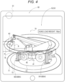
- Fig. 4 is a drawing that illustrates an image displayed on the image display unit 52 according to the first embodiment.
- the functional configuration of the crane information display system 100 according to the first embodiment will be described.
- the crane information display system 100 is such that an image of the first information display unit 41 imaged with the camera 51, an image of the second information display unit 42 imaged with the camera 51, and input information input into the input unit 53 are input into the control unit 60 (in the present embodiment, a control unit incorporated in the tablet terminal 50), and information controlled by the control unit 60 is output on the image display unit 52.
- the control unit 60 in the present embodiment, a control unit incorporated in the tablet terminal 50
- information controlled by the control unit 60 is output on the image display unit 52.
- the camera 51 may be, for example, the camera 51 that the tablet terminal 50 that is common includes.
- the camera 51 can image a work site in which the crane 1 is going to be installed, the first information display unit 41, and the second information display unit 42.
- the length of the boom 30 is the length of the boom 30 in a state in which the front end boom 36 and the intermediate booms 32 to 35 are accommodated in the base end boom 31 (a completely contracted state), the length of the boom 30 in a state in which the front end boom 36 extends, the length of the boom 30 in a state in which the front end boom 36 and the intermediate booms 32 to 35 extend (a completely extending state), or the like.
- the control unit 60 includes a storage unit 61, a crane information acquisition unit 62, a virtual crane generation unit 65, a position/posture calculation unit 66, a position calculation unit 67, and an information processing unit 68.
- the control unit 60 is, for example, a widely-known microcomputer that includes a central processing unit (CPU), random access memory (RAM), read only memory (ROM), and the like.
- control unit 60 (the crane information acquisition unit 62, the virtual crane generation unit 65, the position/posture calculation unit 66, and the position calculation unit 67, and the information processing unit 68) are realized by, for example, the CPU referring to control programs and various data stored in the storage unit 61 (e.g., a hard disk drive (HDD), the ROM, or the RAM).
- storage unit 61 e.g., a hard disk drive (HDD), the ROM, or the RAM.
- the storage unit 61 stores shape information about various types of cranes, and performance information about various types of cranes.
- the performance information includes, for example, information regarding the shapes of the outriggers 80, information regarding possible work area in a horizontal direction and information regarding possible work area in a height direction that correspond to the protrusion amount of the outriggers 80 and the length of the boom 30, information regarding a range of angles by which the boom is raised or lowered, information regarding load ratios, information regarding a tail swing area, and the like.
- the crane information acquisition unit 62 acquires information about the machine type of the crane 1, and acquires, from the storage unit 61, shape information and performance information about the acquired machine type of the crane 1. That is to say, the crane information acquisition unit 62 reads into the first information display unit 41 imaged with the camera 51 (that is to say, reads display information of the first information display unit 41 from the camera image), acquires the machine type of the crane 1, and acquires, from the storage unit 61, shape information and performance information about the acquired machine type.
- the crane information acquisition unit 62 includes a virtual outrigger generation unit 63, and a possible work area calculation unit 64.
- the virtual outrigger generation unit 63 On the basis of information regarding the shapes of the outriggers 80 stored in the storage unit 61 (that is to say, the shapes of the outriggers 80 that correspond to the machine type of the crane 1 specified from display information of an information display unit 40), and a protrusion amount by which the outriggers 80 protrude in a horizontal direction that has been input into the input unit 53, the virtual outrigger generation unit 63 generates three-dimensional data on virtual outriggers 80A, as information about the crane 1.
- the possible work area calculation unit 64 refers to information about the machine type of the crane 1 specified from the display information of the information display unit 40, and calculates possible work area of the crane 1, as information about the crane 1, on the basis of a hung load weight and the length of the boom 30 input into the input unit 53.
- the possible work area calculation unit 64 can calculate possible work area for a plurality of load ratios. In the first embodiment, the possible work area calculation unit 64 calculates a possible work area for a load ratio of 80%, and a possible work area for a load ratio of 100%. Note that the possible work area is an area in which the crane 1 can work in a horizontal direction, in a plane in which the crane 1 is installed.
- the virtual crane generation unit 65 generates three-dimensional data on a virtual crane 1A, on the basis of the information about the crane 1 acquired by the crane information acquisition unit 62.
- the position/posture calculation unit 66 calculates the position and posture of the virtual crane 1A (that is to say, the position at which the virtual crane 1A is to be disposed and the posture to be taken by the virtual crane 1A in the image of the camera 51) on the basis of the first information display unit 41 imaged with the camera 51.
- the position/posture calculation unit 66 acquires information about the posture of the virtual crane 1A, on the basis of the shape of the first information display unit 41 imaged with the camera 51 (hereinafter referred to as an "outline shape of the information display unit 40"), and the reference shape of the first information display unit 41 stored in the first information display unit 41. That is to say, the position/posture calculation unit 66 reads, from an image of the camera 51, display information (that is to say, code information) of the first information display unit 41 to acquire information regarding the reference shape of the first information display unit 41, and extracts, from the image of the camera 51, an outline shape of the first information display unit 41 that appears in the camera 51 by publicly-known pattern matching, or the like.
- display information that is to say, code information
- the position/posture calculation unit 66 compares the outline shape of the first information display unit 41 that appears in the image of the camera 51, with the reference shape of the first information display unit 41 to calculate the position at which the virtual crane 1A is to be disposed and the posture to be taken by the virtual crane 1A in the image of the camera 51.
- the posture is such that the left side surface of the virtual crane 1A is right in front of the camera 51.
- the posture is such that the left side surface of the virtual crane 1A slightly faces left from right in front of the camera 51.
- the posture is such that the left side surface of the virtual crane 1A slightly faces right from right in front of the camera 51.
- the position/posture calculation unit 66 compares the outline shape of the first information display unit 41 imaged with the camera 51, with the reference shape of the first information display unit 41 stored in the first information display unit 41 to acquire information about the posture of the virtual crane 1A.
- the position/posture calculation unit 66 acquires information about the position of the virtual crane 1A, on the basis of the size of the outline shape of the first information display unit 41 imaged with the camera 51, and the reference size of the first information display unit 41 stored in the first information display unit 41. More specifically, the position/posture calculation unit 66 compares the reference size of the first information display unit 41 stored in the first information display unit 41 with the size of the outline shape of the first information display unit 41 imaged with the camera 51 to calculate the distance from the camera 51 to the first information display unit 41.
- the position calculation unit 67 calculates information about a relative position of the second information display unit 42 from the first information display unit 41, on the basis of the second information display unit 42 imaged with the camera 51. More specifically, the position calculation unit 67 reads into the second information display unit 42 imaged with the camera 51 (that is to say, reads, from the image of the camera 51, display information of the second information display unit 42), and calculates the distance and direction from the first information display unit 41, with the position of the first information display unit 41 as the reference. That is to say, the position calculation unit 67 calculates information about the distance of the second information display unit 42 in a horizontal direction, and information about the distance of the second information display unit 42 in a height direction, with the first information display unit 41 as the reference.
- the position calculation unit 67 functions in a state in which the first information display unit 41 and the second information display unit 42 both appear in an image of the camera 51.
- the position calculation unit 67 acquires the reference shape of the second information display unit 42, extracts an outline shape of the second information display unit 42 that appears in an image of the camera 51, and specifies the position of the second information display unit 42 in the image of the camera 51, on the basis of information about the reference shape of the second information display unit 42, and the outline shape of the second information display unit 42.
- the position calculation unit 67 refers to the position of the first information display unit 41 in the image of the camera 51 calculated by the position/posture calculation unit 66, and the position of the second information display unit 42 in the image of the camera 51 calculated by the position calculation unit 67 to calculate information about the relative position of the second information display unit 42 from the first information display unit 41.
- the positional relationship between an image of the camera 51 in which a first information display unit 41 appears and an image of the camera 51 in which a second information display unit 42 appears is specified by simultaneous localization and mapping (SLAM) technology or the like, the function of the position calculation unit 67 can be realized even if the first information display unit 41 and the second information display unit 42 both do not appear in one image.
- SLAM simultaneous localization and mapping
- the information processing unit 68 processes the virtual crane 1A generated by the virtual crane generation unit 65, into information that corresponds to the position and posture of the virtual crane 1A calculated by the position/posture calculation unit 66.
- the information processing unit 68 converts image information about the virtual crane 1A generated by the virtual crane generation unit 65, into image information that corresponds to the position at which the virtual crane 1A is to be disposed and the posture to be taken by the virtual crane 1A in an image of the camera 51 calculated by the position/posture calculation unit 66.
- the information processing unit 68 converts image information about the virtual crane 1A in such a manner that when a position at which the crane is going to be installed (that is to say, a position at which the first information display unit 41 is installed) is seen from the imaging position of the camera 51, a three-dimensional image of the virtual crane 1A becomes an image that simulates a state in which the crane 1 actually exists.
- image processing by the information processing unit 68 is realized by publicly-known coordinate conversion processing or the like.
- the information processing unit 68 processes the performance information about the crane 1 acquired by the crane information acquisition unit 62, the virtual outriggers 80A generated by the virtual outrigger generation unit 63, and the possible work area of the crane 1 calculated by the possible work area calculation unit 64, into information that corresponds to the position and posture of the virtual crane 1A calculated by the position/posture calculation unit 66. That is to say, the information processing unit 68 processes the information about the crane 1 acquired by the crane information acquisition unit 62, into information that corresponds to the position and posture of the virtual crane 1A calculated by the position/posture calculation unit 66.
- the information processing unit 68 processes the information about the crane 1 acquired by the crane information acquisition unit 62, into information that corresponds to the position and posture of the virtual crane 1A calculated by the position/posture calculation unit 66, with the second information display unit 42 as the reference.
- the information processing unit 68 processes the information about the crane 1 that has been made to correspond to the position and posture of the virtual crane 1A calculated by the position/posture calculation unit 66, into information with the second information display unit 42 as the reference.
- the information processing unit 68 converts the information about the crane 1 acquired by the crane information acquisition unit 62 (for example, possible work area 75 and 76 of the crane 1), into three-dimensional image information in which the information about the crane 1 acquired by the crane information acquisition unit 62 (for example, the possible work area 75 and 76 of the crane 1) corresponds to a work position at a time when the crane 1 unloads a hung load.
- the image display unit 52 overlays and displays the information processed by the information processing unit 68 onto an image of the camera 51. More specifically, as illustrated in Fig. 4 , the image display unit 52 superimposes and displays, on an image of a work site imaged with the camera 51 in which the crane 1 is going to be installed, the virtual crane 1A, a tail swing area 73 of the crane 1 acquired by the crane information acquisition unit 62, the virtual outriggers 80A generated by the virtual outrigger generation unit 63, possible work area 71 and 72 in a plane in which the crane 1 is installed that has been calculated by the possible work area calculation unit 64, and possible work area 75 and 76 of the crane 1 at the height at which the second information display unit 42 is disposed. Further, the image display unit 52 displays a hung load weight input into the input unit 53.
- the virtual outriggers 80A include virtual front outriggers 82A and virtual rear outriggers 81A.
- the possible work area in a plane in which the crane 1 is installed include the possible work area 72 for a load ratio of 80%, and the possible work area 71 for a load ratio of 100%.
- the possible work area at the height at which the second information display unit 42 is disposed include the possible work area 76 for a load ratio of 80%, and the possible work area 75 for a load ratio of 100%.
- Fig. 5 is a flowchart that illustrates a process of processing by the control unit 60 of the crane information display system 100 according to the first embodiment.
- the process of processing by the control unit 60 of the crane information display system 100 according to the first embodiment will be described.
- the crane information acquisition unit 62 reads into the first information display unit 41 imaged with the camera 51, as illustrated in Fig. 5 (step S101).
- the crane information acquisition unit 62 acquires, from the storage unit 61, shape information and performance information about the machine type of the crane 1 that has been acquired (step S102).
- the virtual crane generation unit 65 generates three-dimensional data on virtual outriggers, on the basis of information about the crane 1 acquired by the crane information acquisition unit 62 (step S103).
- control unit 60 determines whether or not a hung load weight and the length of the boom 30 have been input into the input unit 53 (step S107). If it is determined that a hung load weight and the length of the boom 30 have been input into the input unit 53 (YES in step S107), the possible work area calculation unit 64 calculates possible work area 71 and 72 (step S108), and the processing proceeds to step 109. On the other hand, if it is determined that a hung load weight and the length of the boom 30 have not been input into the input unit 53 (NO in step S108), the processing proceeds to step S109.
- the information processing unit 68 processes the virtual outriggers 80A generated by the virtual outrigger generation unit 63, and the information about the crane 1 acquired by the crane information acquisition unit 62, into information that corresponds to the position and posture of the crane 1 calculated by the position/posture calculation unit 66 (step S109).
- the position calculation unit 67 reads into the second information display unit 42 imaged with the camera 51 (step S110).
- the position calculation unit 67 calculates position information about the second information display unit 42 from the first information display unit 41 (step S111).
- the information processing unit 68 processes the information about the crane 1 acquired by the crane information acquisition unit 62, into information that corresponds to the position and posture of the virtual crane 1A calculated by the position/posture calculation unit 66, with the second information display unit 42 as the reference (step S112) .
- the image display unit 52 superimposes and displays, on an image of a work site imaged with the camera 51 in which the crane 1 is going to be installed, the virtual crane 1A, a tail swing area 73 of the crane 1 acquired by the crane information acquisition unit 62, the virtual outriggers 80A generated by the virtual outrigger generation unit 63, possible work area 71 and 72 in a plane in which the virtual crane 1A is installed, and possible work area 75 and 76 at the height at which the second information display unit 42 is disposed (step S113), and the processing is ended.
- the crane 1 is carried and installed in such a manner that a predetermined position of the actual crane 1 (e.g., the center of the left side surface of the vehicle body frame 11 of the travelling body 10) is made to correspond to the first information display unit 41 attached to the support member 45 put in the work site.
- a predetermined position of the actual crane 1 e.g., the center of the left side surface of the vehicle body frame 11 of the travelling body
- the crane information display system 100 includes the crane information acquisition unit 62 that images, with the camera 51, the first information display unit 41 that displays information about the crane 1 to acquire the information about the crane 1, the virtual crane generation unit 65 that generates a virtual crane 1A of the crane 1 that is three-dimensional, on the basis of the information about the crane 1 acquired by the crane information acquisition unit 62, the position/posture calculation unit 66 that calculates the position and posture of the virtual crane 1A, on the basis of the first information display unit 41 imaged with the camera 51, the information processing unit 68 that processes the virtual crane 1A generated by the virtual crane generation unit 65, into information that corresponds to the position and posture of the virtual crane 1A calculated by the position/posture calculation unit 66, and the image display unit 52 that overlays and displays the information processed by the information processing unit 68 onto the image imaged with the camera 51 ( Figs. 3 and 4 ).
- the virtual crane 1A can be disposed and displayed in a scenery image of a place in which the crane 1 is going to be installed. Therefore, disposition of the crane 1 can be examined in a three-dimensional image without actually disposing the crane 1 in a place in which the crane 1 is going to be installed. As a result, a work plan of the crane 1 can be easily examined.
- the information processing unit 68 processes information about the crane 1 acquired by the crane information acquisition unit 62, into information that corresponds to the position and posture of a virtual crane 1A calculated by the position/posture calculation unit 66 ( Figs. 3 and 4 ).
- the information about the crane 1 can be overlaid and displayed onto an image in which the virtual crane 1A is disposed. Therefore, the virtual crane 1A, a site environment around the virtual crane 1A, and the information about the crane 1 can be checked in a three-dimensional image in real time. As a result, a work plan of the crane 1 can be easily examined without disposing the actual crane 1 in a place in which the crane 1 is going to be installed.
- the second information display unit 42 is provided and disposed at a position onto which the crane 1 unloads a hung load, the second information display unit 42 is imaged with the camera 51, the position calculation unit 67 calculates position information about the second information display unit 42 from the first information display unit 41, and the information processing unit 68 processes, on the basis of the position information calculated by the position calculation unit 67, information about the crane 1 acquired by the crane information acquisition unit 62, into information that corresponds to the position and posture of a virtual crane 1A calculated by the position/posture calculation unit 66, with the second information display unit 42 as the reference ( Figs. 3 and 4 ).
- possible work area 75 and 76 at the height at which the second information display unit 42 is installed can be displayed. Therefore, for example, if work that unloads a hung load is performed at a high position, such as a rooftop of a building B, as illustrated in Fig. 4 , possible work area 75 and 76 of the crane 1 at the height at which the second information display unit 42 is installed can be displayed. As a result, even if a position onto which a hung load is unloaded is at a height different from the height of a plane in which the crane 1 is installed, a work plan of the crane 1 can be easily examined.
- the input unit 53 into which a protrusion amount of the outriggers 80 of a virtual crane 1A is input is provided, and the crane information acquisition unit 62 includes the virtual outrigger generation unit 63 that generates three-dimensional virtual outriggers 80A, on the basis of the input value input into the input unit 53 ( Figs. 3 and 4 ).
- the virtual outriggers 80A of a protrusion amount that corresponds to the input value can be overlaid and displayed onto an image in which the virtual crane 1A disposed in a place in which the crane 1 is going to be installed, and the surroundings around the virtual crane 1A are imaged. Therefore, a protrusion amount of the outriggers 80 can be checked in a three-dimensional image in real time in the work site.
- the input unit 53 into which a hung load weight and the length of the boom 30 of the crane 1 are input is provided, and the crane information acquisition unit 62 includes the possible work area calculation unit 64 that calculates possible work area 71 and 72 of the crane 1, on the basis of the input values input into the input unit 53 ( Figs. 3 and 4 ).
- the possible work area 71 and 72 for a predetermined hung load weight can be overlaid and displayed, on the basis of the length of the boom 30, onto an image in which a virtual crane 1A disposed in a place in which the crane 1 is going to be installed and the surroundings around the virtual crane 1A are imaged. Therefore, the possible work area 71 and 72 can be checked in a three-dimensional image in real time in the work site.
- information about the crane 1 includes a tail swing area 73 of the crane 1 ( Figs. 3 and 4 ).
- the tail swing area 73 can be overlaid and displayed onto an image in which a virtual crane 1A disposed in a place in which the crane 1 is going to be installed and the surroundings around the virtual crane 1A are imaged. Therefore, the tail swing area 73 can be checked in a three-dimensional image in real time in the work site.
- information about a predetermined position of the crane 1 stored in the first information display unit 41 is the center of the left side surface of the vehicle body frame 11 of the travelling body 10.
- information about a predetermined position of the crane 1 stored in the first information display unit 41 is not limited to the center of the left side surface of the vehicle body frame 11.
- the front surface, the back surface, and the right side surface of the vehicle body frame 11 may be stored as information about predetermined positions of the crane 1 stored in the first information display unit 41, and a worker M may appropriately perform the selection with the input unit 53.
- the first information display unit 41 In the first embodiment, an example is shown in which information about the machine type of the one crane 1 is stored in the first information display unit 41. However, information about a plurality of machine types of cranes may be stored in the first information display unit 41, and a worker M may appropriately perform the selection with the input unit 53.
- an information display unit 40 is an AprilTag.
- an information display unit is not limited to the aspect, but may be, for example, a two-dimensional code, such as a QR code (registered trademark).
- an information display unit may be a crane itself, and information about the crane may be acquired by image recognition using deep learning.
- the possible work area 72 and 76 for a load ratio of 80%, and the possible work area 71 and 75 for a load ratio of 100% are displayed on the image display unit 52.
- one possible work area may be displayed, or three or more possible work area may be displayed on an image display unit.
- load ratios of possible work area are not limited to 80% and 100%.
- a user terminal is the tablet terminal 50 that includes the camera 51, the input unit 53, and the image display unit 52.
- the user terminal may be a smartphone.
- the user terminal may include a camera and an image display unit that are separate.
- shape information and performance information of the crane 1 are stored in the storage unit 61.
- shape information and performance information of a crane may be stored in the first information display unit.
Landscapes
- Engineering & Computer Science (AREA)
- Mechanical Engineering (AREA)
- Automation & Control Theory (AREA)
- Jib Cranes (AREA)
- Lead Frames For Integrated Circuits (AREA)
- Structures For Mounting Electric Components On Printed Circuit Boards (AREA)
- Processing Or Creating Images (AREA)
Claims (6)
- Kraninformationsanzeigesystem (100), umfassend:eine erste Informationsanzeigeeinheit (41), die an dem Ort installiert ist, an dem ein Kran (1) installiert werden soll, und die so konfiguriert ist, dass sie Informationen über den Kran (1) anzeigt, undein Endgerät (50), das eine Kamera (51) trägt, um durch Abbilden der ersten Informationsanzeigeeinheit (41) mit der Kamera (51) ein Kamerabild zu erhalten,wobei das Endgerät (50) umfasst:eine Kraninformationserfassungseinheit (62), die so konfiguriert ist, dass sie aus dem Kamerabild Anzeigeinformationen der ersten Informationsanzeigeeinheit (41) abliest, um Informationen über den Kran (1) zu erfassen;eine Erzeugungseinheit für virtuelle Kräne (65), die so konfiguriert ist, dass sie auf der Grundlage der von der Kraninformationserfassungseinheit (62) erfassten Informationen über den Kran (1) Bildinformationen über einen virtuellen Kran (1A) erzeugt, die einem dreidimensionalen Bild des Krans (1) entsprechen;eine Positions-/Stellungsberechnungseinheit (66), die so konfiguriert ist, dass sie aus dem Kamerabild die Anzeigeinformationen der ersten Informationsanzeigeeinheit (41) abliest, um Informationen über eine Referenzform der ersten Informationsanzeigeeinheit (41) zu erfassen, und aus dem Kamerabild Informationen über eine Umrissform der ersten Informationsanzeigeeinheit (41) extrahiert, die im Kamerabild erscheint, und auf der Grundlage der Referenzform der ersten Informationsanzeigeeinheit (41) und der Informationen über die Umrissform der ersten Informationsanzeigeeinheit (41) eine Position, an der der virtuelle Kran (1A) anzuordnen ist, und eine Stellung, die der virtuelle Kran (1A) im Kamerabild einnehmen soll, berechnet;eine Informationsverarbeitungseinheit (68), die so konfiguriert ist, dass sie die von der Erzeugungseinheit für virtuelle Kräne (65) erzeugten Bildinformationen über den virtuellen Kran (1A) in Bildinformationen umwandelt, die der von der Positions-/Stellungsberechnungseinheit (66) berechneten Position und Stellung des virtuellen Krans (1A) entsprechen; undeine Bildanzeigeeinheit (52), die so konfiguriert ist, dass sie den virtuellen Kran (1A), auf den die Verarbeitung durch die zur Umwandlung der Bildinformationen konfigurierte Informationsverarbeitungseinheit (66) angewendet wurde, über das Kamerabild legt und anzeigt.
- Kraninformationsanzeigesystem (100) gemäß Anspruch 1, wobeidie Informationsverarbeitungseinheit (68) so konfiguriert ist, dass sie die von der Kraninformationserfassungseinheit (62) erfassten Informationen über den Kran in dreidimensionale Bildinformationen umwandelt, die der von der Positions-/ Stellungsberechnungseinheit (66) berechneten Position und Stellung des virtuellen Krans (1A) entsprechen, unddie Bildanzeigeeinheit (52) so konfiguriert ist, dass sie auf dem Kamerabild die Informationen über den Kran (1) anzeigt, auf die die Verarbeitung durch die Informationsverarbeitungseinheit (68) angewendet wurde.
- Kraninformationsanzeigesystem (100) gemäß Anspruch 2, wobei das Kraninformationsanzeigesystem (100) ferner eine zweite Informationsanzeigeeinheit (42) umfasst, die an einer Position installiert ist, an der der Kran (1) eine hängende Last entladen soll,
wobei das Endgerät (50) ferner umfasst:eine Positionsberechnungseinheit (67), die so konfiguriert ist, dass sie aus dem Kamerabild Anzeigeinformationen der zweiten Informationsanzeigeeinheit (42) abliest, um eine Referenzform der zweiten Informationsanzeigeeinheit (42) zu erfassen, und aus dem Kamerabild Informationen über eine Umrissform der zweiten Informationsanzeigeeinheit (42) extrahiert, die in dem Kamerabild erscheint, zu extrahieren, und auf der Grundlage der Referenzform der zweiten Informationsanzeigeeinheit (42) und der Information über die Umrissform der zweiten Informationsanzeigeeinheit (42) eine relative Position der zweiten Informationsanzeigeeinheit (42) gegenüber der ersten Informationsanzeigeeinheit (41) zu berechnen, undwobeidie Informationsverarbeitungseinheit (68) so konfiguriert ist, dass sie auf der Grundlage der relativen Position der zweiten Informationsanzeigeeinheit (42) gegenüber der ersten Informationsanzeigeeinheit (41) die von der Kraninformationserfassungseinheit (62) erfassten Informationen über den Kran (1) in die dreidimensionalen Bildinformationen umwandelt, die einer Arbeitsposition zu einem Zeitpunkt, zu dem der Kran (1) die hängende Last entlädt, entsprechen. - Kraninformationsanzeigesystem (100) gemäß Anspruch 2, wobei das Endgerät (50) ferner eine Eingabeeinheit (53) umfasst, die konfiguriert ist, um eine Eingabe einer Höhe eines Vorsprungs einer Stütze des virtuellen Krans (1A) zu empfangen, und
wobei die Kraninformationserfassungseinheit (62) so konfiguriert ist, dass sie auf der Grundlage von Informationen über eine Stütze des Krans (1), die von den Anzeigeinformationen der ersten Informationsanzeigeeinheit (41) festgelegt werden, und eines in die Eingabeeinheit (53) eingegebenen Eingabewerts Bildinformationen über eine virtuelle Stütze (80A) erzeugt, die einem dreidimensionalen Bild der Stütze als Informationen über den Kran (1) als Anzeigeobjekt entsprechen. - Kraninformationsanzeigesystem (100) gemäß Anspruch 2, wobei das Endgerät (50) ferner eine Eingabeeinheit (53) umfasst, die so konfiguriert ist, dass sie eine Eingabe eines Gewichts einer hängenden Last und einer Länge eines Auslegers des Krans (1) empfängt, und
wobei die Kraninformationserfassungseinheit (62) so konfiguriert ist, dass sie, auf der Grundlage von Informationen über einen Maschinentyp des Krans, die von den Anzeigeinformationen der ersten Informationsanzeigeeinheit (41) festgelegt werden, und von in die Eingabeeinheit (53) eingegebenen Eingabewerten einen möglichen Arbeitsbereich des Krans (1) als Information über den Kran (1) als Anzeigeobjekt berechnet. - Kraninformationsanzeigesystem (100) nach Anspruch 1, wobei
die Informationen über den Kran Informationen über einen Heckausschwenkbereich (73) des Krans (1) enthalten.
Applications Claiming Priority (2)
| Application Number | Priority Date | Filing Date | Title |
|---|---|---|---|
| JP2019176782 | 2019-09-27 | ||
| PCT/JP2020/036296 WO2021060473A1 (ja) | 2019-09-27 | 2020-09-25 | クレーン情報表示システム |
Publications (3)
| Publication Number | Publication Date |
|---|---|
| EP4036046A1 EP4036046A1 (de) | 2022-08-03 |
| EP4036046A4 EP4036046A4 (de) | 2023-11-01 |
| EP4036046B1 true EP4036046B1 (de) | 2024-12-18 |
Family
ID=75165248
Family Applications (1)
| Application Number | Title | Priority Date | Filing Date |
|---|---|---|---|
| EP20869570.0A Active EP4036046B1 (de) | 2019-09-27 | 2020-09-25 | Kraninformationsanzeigesystem |
Country Status (4)
| Country | Link |
|---|---|
| US (1) | US12172871B2 (de) |
| EP (1) | EP4036046B1 (de) |
| JP (1) | JP7070802B2 (de) |
| WO (1) | WO2021060473A1 (de) |
Families Citing this family (5)
| Publication number | Priority date | Publication date | Assignee | Title |
|---|---|---|---|---|
| DE102019113881A1 (de) * | 2019-02-12 | 2020-08-13 | Putzmeister Engineering Gmbh | Betonpumpe und Verfahren zum Abstützen einer Betonpumpe |
| WO2021060471A1 (ja) * | 2019-09-27 | 2021-04-01 | 株式会社タダノ | クレーン情報表示システム |
| JP7593213B2 (ja) * | 2021-04-21 | 2024-12-03 | 株式会社タダノ | アウトリガ装置の設置位置表示システム及び作業車両 |
| AT17868U1 (de) * | 2021-12-02 | 2023-05-15 | Palfinger Ag | Verfahren zur indirekten Bestimmung einer Ausschublänge zumindest eines Teleskopschubarmes eines Teleskopauslegers |
| EP4629194A1 (de) | 2024-04-05 | 2025-10-08 | Panasonic Intellectual Property Management Co., Ltd. | Verfahren zur fernsteuerung, endgerätevorrichtung und programm |
Family Cites Families (11)
| Publication number | Priority date | Publication date | Assignee | Title |
|---|---|---|---|---|
| JP2004001987A (ja) * | 2002-03-25 | 2004-01-08 | Hitachi Constr Mach Co Ltd | 操作支援装置 |
| JP5831149B2 (ja) * | 2011-11-14 | 2015-12-09 | コニカミノルタ株式会社 | シミュレーション方法、シミュレーション装置およびシミュレーション装置の制御プログラム |
| JP2014227281A (ja) | 2013-05-24 | 2014-12-08 | 株式会社タダノ | 作業機の表示システム |
| NL2013409B1 (en) * | 2014-09-03 | 2016-09-27 | Fugro N V | Spatial positioning of offshore structures. |
| US10499996B2 (en) | 2015-03-26 | 2019-12-10 | Universidade De Coimbra | Methods and systems for computer-aided surgery using intra-operative video acquired by a free moving camera |
| JP6306552B2 (ja) * | 2015-10-13 | 2018-04-04 | 株式会社タダノ | 遠隔操作装置、及び案内システム |
| DE102016000351A1 (de) * | 2016-01-14 | 2017-07-20 | Liebherr-Werk Biberach Gmbh | Kran-, Baumaschinen- oder Flurförderzeug-Simulator |
| DE102016004382A1 (de) * | 2016-04-08 | 2017-10-12 | Liebherr-Werk Biberach Gmbh | Verfahren und Vorrichtung zum Planen und/oder Steuern und/oder Simulieren des Betriebs einer Baumaschine |
| DE102016004266A1 (de) * | 2016-04-08 | 2017-10-12 | Liebherr-Werk Biberach Gmbh | Baumaschine, insbesondere Kran, und Verfahren zu deren Steuerung |
| JP6460294B2 (ja) * | 2016-12-27 | 2019-01-30 | 株式会社タダノ | 遠隔操作端末及び遠隔操作システム |
| JP6979384B2 (ja) | 2018-03-30 | 2021-12-15 | グローブライド株式会社 | 魚釣用スピニングリール |
-
2020
- 2020-09-25 US US17/763,051 patent/US12172871B2/en active Active
- 2020-09-25 WO PCT/JP2020/036296 patent/WO2021060473A1/ja not_active Ceased
- 2020-09-25 JP JP2021549047A patent/JP7070802B2/ja active Active
- 2020-09-25 EP EP20869570.0A patent/EP4036046B1/de active Active
Also Published As
| Publication number | Publication date |
|---|---|
| JPWO2021060473A1 (de) | 2021-04-01 |
| JP7070802B2 (ja) | 2022-05-18 |
| US12172871B2 (en) | 2024-12-24 |
| WO2021060473A1 (ja) | 2021-04-01 |
| EP4036046A1 (de) | 2022-08-03 |
| EP4036046A4 (de) | 2023-11-01 |
| US20220356048A1 (en) | 2022-11-10 |
Similar Documents
| Publication | Publication Date | Title |
|---|---|---|
| EP4036046B1 (de) | Kraninformationsanzeigesystem | |
| JP6589468B2 (ja) | 移動式クレーンの周囲表示装置 | |
| US20190016569A1 (en) | Method and apparatus for controlling a crane, an excavator, a crawler-type vehicle or a similar construction machine | |
| US11292699B2 (en) | Remote operation terminal and work vehicle provided with remote operation terminal | |
| CN114080481A (zh) | 施工机械及支援基于施工机械的作业的支援装置 | |
| US12012310B2 (en) | Crane information display system | |
| JP5091447B2 (ja) | 作業機搭載車両の周辺監視支援装置 | |
| JP2018039477A (ja) | 画像表示システム | |
| JP2019218198A (ja) | 操作支援システム | |
| EP4036047B1 (de) | Kraninformationsanzeigesystem | |
| JP7596738B2 (ja) | 作業車両 | |
| JP2020066520A (ja) | クレーン車 | |
| JPH08123938A (ja) | 遠隔操作用監視装置 | |
| JP2023121468A (ja) | クレーンの操縦支援システム及び操縦支援システムを有するクレーン | |
| JP7593213B2 (ja) | アウトリガ装置の設置位置表示システム及び作業車両 | |
| JP7303094B2 (ja) | 作業車 | |
| JP7336363B2 (ja) | 作業車 | |
| JP7620396B2 (ja) | 作業車 | |
| JP2018095362A (ja) | クレーン | |
| JP7800195B2 (ja) | 作業車両の操縦支援システム及び操縦支援システムを有する作業車両 | |
| US20250026617A1 (en) | Maneuvering assistance system and work vehicle | |
| JP2023120017A (ja) | クレーンのブーム自動化装置、クレーンのブーム制御方法およびプログラム | |
| JP2025080701A (ja) | 作業車両配置支援システム | |
| JP2025108848A (ja) | 作業機械の周辺監視装置 | |
| WO2026023663A1 (ja) | 作業車両の遠隔操作装置 |
Legal Events
| Date | Code | Title | Description |
|---|---|---|---|
| STAA | Information on the status of an ep patent application or granted ep patent |
Free format text: STATUS: THE INTERNATIONAL PUBLICATION HAS BEEN MADE |
|
| PUAI | Public reference made under article 153(3) epc to a published international application that has entered the european phase |
Free format text: ORIGINAL CODE: 0009012 |
|
| STAA | Information on the status of an ep patent application or granted ep patent |
Free format text: STATUS: REQUEST FOR EXAMINATION WAS MADE |
|
| 17P | Request for examination filed |
Effective date: 20220328 |
|
| AK | Designated contracting states |
Kind code of ref document: A1 Designated state(s): AL AT BE BG CH CY CZ DE DK EE ES FI FR GB GR HR HU IE IS IT LI LT LU LV MC MK MT NL NO PL PT RO RS SE SI SK SM TR |
|
| DAV | Request for validation of the european patent (deleted) | ||
| DAX | Request for extension of the european patent (deleted) | ||
| A4 | Supplementary search report drawn up and despatched |
Effective date: 20231004 |
|
| RIC1 | Information provided on ipc code assigned before grant |
Ipc: B66C 13/40 20060101ALI20230927BHEP Ipc: B66C 23/90 20060101ALI20230927BHEP Ipc: B66C 23/00 20060101ALI20230927BHEP Ipc: B66C 13/46 20060101AFI20230927BHEP |
|
| GRAP | Despatch of communication of intention to grant a patent |
Free format text: ORIGINAL CODE: EPIDOSNIGR1 |
|
| RIC1 | Information provided on ipc code assigned before grant |
Ipc: B66C 13/40 20060101ALI20240702BHEP Ipc: B66C 23/90 20060101ALI20240702BHEP Ipc: B66C 23/00 20060101ALI20240702BHEP Ipc: B66C 13/46 20060101AFI20240702BHEP |
|
| STAA | Information on the status of an ep patent application or granted ep patent |
Free format text: STATUS: GRANT OF PATENT IS INTENDED |
|
| INTG | Intention to grant announced |
Effective date: 20240808 |
|
| GRAS | Grant fee paid |
Free format text: ORIGINAL CODE: EPIDOSNIGR3 |
|
| GRAA | (expected) grant |
Free format text: ORIGINAL CODE: 0009210 |
|
| STAA | Information on the status of an ep patent application or granted ep patent |
Free format text: STATUS: THE PATENT HAS BEEN GRANTED |
|
| AK | Designated contracting states |
Kind code of ref document: B1 Designated state(s): AL AT BE BG CH CY CZ DE DK EE ES FI FR GB GR HR HU IE IS IT LI LT LU LV MC MK MT NL NO PL PT RO RS SE SI SK SM TR |
|
| REG | Reference to a national code |
Ref country code: CH Ref legal event code: EP |
|
| REG | Reference to a national code |
Ref country code: DE Ref legal event code: R096 Ref document number: 602020043502 Country of ref document: DE |
|
| REG | Reference to a national code |
Ref country code: IE Ref legal event code: FG4D |
|
| REG | Reference to a national code |
Ref country code: LT Ref legal event code: MG9D |
|
| PG25 | Lapsed in a contracting state [announced via postgrant information from national office to epo] |
Ref country code: HR Free format text: LAPSE BECAUSE OF FAILURE TO SUBMIT A TRANSLATION OF THE DESCRIPTION OR TO PAY THE FEE WITHIN THE PRESCRIBED TIME-LIMIT Effective date: 20241218 |
|
| PG25 | Lapsed in a contracting state [announced via postgrant information from national office to epo] |
Ref country code: FI Free format text: LAPSE BECAUSE OF FAILURE TO SUBMIT A TRANSLATION OF THE DESCRIPTION OR TO PAY THE FEE WITHIN THE PRESCRIBED TIME-LIMIT Effective date: 20241218 |
|
| PG25 | Lapsed in a contracting state [announced via postgrant information from national office to epo] |
Ref country code: BG Free format text: LAPSE BECAUSE OF FAILURE TO SUBMIT A TRANSLATION OF THE DESCRIPTION OR TO PAY THE FEE WITHIN THE PRESCRIBED TIME-LIMIT Effective date: 20241218 |
|
| PG25 | Lapsed in a contracting state [announced via postgrant information from national office to epo] |
Ref country code: NO Free format text: LAPSE BECAUSE OF FAILURE TO SUBMIT A TRANSLATION OF THE DESCRIPTION OR TO PAY THE FEE WITHIN THE PRESCRIBED TIME-LIMIT Effective date: 20250318 |
|
| REG | Reference to a national code |
Ref country code: NL Ref legal event code: MP Effective date: 20241218 |
|
| PG25 | Lapsed in a contracting state [announced via postgrant information from national office to epo] |
Ref country code: GR Free format text: LAPSE BECAUSE OF FAILURE TO SUBMIT A TRANSLATION OF THE DESCRIPTION OR TO PAY THE FEE WITHIN THE PRESCRIBED TIME-LIMIT Effective date: 20250319 Ref country code: LV Free format text: LAPSE BECAUSE OF FAILURE TO SUBMIT A TRANSLATION OF THE DESCRIPTION OR TO PAY THE FEE WITHIN THE PRESCRIBED TIME-LIMIT Effective date: 20241218 |
|
| PG25 | Lapsed in a contracting state [announced via postgrant information from national office to epo] |
Ref country code: RS Free format text: LAPSE BECAUSE OF FAILURE TO SUBMIT A TRANSLATION OF THE DESCRIPTION OR TO PAY THE FEE WITHIN THE PRESCRIBED TIME-LIMIT Effective date: 20250318 |
|
| PG25 | Lapsed in a contracting state [announced via postgrant information from national office to epo] |
Ref country code: NL Free format text: LAPSE BECAUSE OF FAILURE TO SUBMIT A TRANSLATION OF THE DESCRIPTION OR TO PAY THE FEE WITHIN THE PRESCRIBED TIME-LIMIT Effective date: 20241218 |
|
| REG | Reference to a national code |
Ref country code: AT Ref legal event code: MK05 Ref document number: 1752129 Country of ref document: AT Kind code of ref document: T Effective date: 20241218 |
|
| PG25 | Lapsed in a contracting state [announced via postgrant information from national office to epo] |
Ref country code: SM Free format text: LAPSE BECAUSE OF FAILURE TO SUBMIT A TRANSLATION OF THE DESCRIPTION OR TO PAY THE FEE WITHIN THE PRESCRIBED TIME-LIMIT Effective date: 20241218 |
|
| PG25 | Lapsed in a contracting state [announced via postgrant information from national office to epo] |
Ref country code: PL Free format text: LAPSE BECAUSE OF FAILURE TO SUBMIT A TRANSLATION OF THE DESCRIPTION OR TO PAY THE FEE WITHIN THE PRESCRIBED TIME-LIMIT Effective date: 20241218 |
|
| PG25 | Lapsed in a contracting state [announced via postgrant information from national office to epo] |
Ref country code: ES Free format text: LAPSE BECAUSE OF FAILURE TO SUBMIT A TRANSLATION OF THE DESCRIPTION OR TO PAY THE FEE WITHIN THE PRESCRIBED TIME-LIMIT Effective date: 20241218 |
|
| PG25 | Lapsed in a contracting state [announced via postgrant information from national office to epo] |
Ref country code: IS Free format text: LAPSE BECAUSE OF FAILURE TO SUBMIT A TRANSLATION OF THE DESCRIPTION OR TO PAY THE FEE WITHIN THE PRESCRIBED TIME-LIMIT Effective date: 20250418 |
|
| PG25 | Lapsed in a contracting state [announced via postgrant information from national office to epo] |
Ref country code: PT Free format text: LAPSE BECAUSE OF FAILURE TO SUBMIT A TRANSLATION OF THE DESCRIPTION OR TO PAY THE FEE WITHIN THE PRESCRIBED TIME-LIMIT Effective date: 20250421 |
|
| PG25 | Lapsed in a contracting state [announced via postgrant information from national office to epo] |
Ref country code: EE Free format text: LAPSE BECAUSE OF FAILURE TO SUBMIT A TRANSLATION OF THE DESCRIPTION OR TO PAY THE FEE WITHIN THE PRESCRIBED TIME-LIMIT Effective date: 20241218 |
|
| PG25 | Lapsed in a contracting state [announced via postgrant information from national office to epo] |
Ref country code: RO Free format text: LAPSE BECAUSE OF FAILURE TO SUBMIT A TRANSLATION OF THE DESCRIPTION OR TO PAY THE FEE WITHIN THE PRESCRIBED TIME-LIMIT Effective date: 20241218 Ref country code: AT Free format text: LAPSE BECAUSE OF FAILURE TO SUBMIT A TRANSLATION OF THE DESCRIPTION OR TO PAY THE FEE WITHIN THE PRESCRIBED TIME-LIMIT Effective date: 20241218 |
|
| PG25 | Lapsed in a contracting state [announced via postgrant information from national office to epo] |
Ref country code: SK Free format text: LAPSE BECAUSE OF FAILURE TO SUBMIT A TRANSLATION OF THE DESCRIPTION OR TO PAY THE FEE WITHIN THE PRESCRIBED TIME-LIMIT Effective date: 20241218 |
|
| PG25 | Lapsed in a contracting state [announced via postgrant information from national office to epo] |
Ref country code: CZ Free format text: LAPSE BECAUSE OF FAILURE TO SUBMIT A TRANSLATION OF THE DESCRIPTION OR TO PAY THE FEE WITHIN THE PRESCRIBED TIME-LIMIT Effective date: 20241218 |
|
| PG25 | Lapsed in a contracting state [announced via postgrant information from national office to epo] |
Ref country code: IT Free format text: LAPSE BECAUSE OF FAILURE TO SUBMIT A TRANSLATION OF THE DESCRIPTION OR TO PAY THE FEE WITHIN THE PRESCRIBED TIME-LIMIT Effective date: 20241218 |
|
| PG25 | Lapsed in a contracting state [announced via postgrant information from national office to epo] |
Ref country code: SE Free format text: LAPSE BECAUSE OF FAILURE TO SUBMIT A TRANSLATION OF THE DESCRIPTION OR TO PAY THE FEE WITHIN THE PRESCRIBED TIME-LIMIT Effective date: 20241218 |
|
| REG | Reference to a national code |
Ref country code: DE Ref legal event code: R097 Ref document number: 602020043502 Country of ref document: DE |
|
| PG25 | Lapsed in a contracting state [announced via postgrant information from national office to epo] |
Ref country code: DK Free format text: LAPSE BECAUSE OF FAILURE TO SUBMIT A TRANSLATION OF THE DESCRIPTION OR TO PAY THE FEE WITHIN THE PRESCRIBED TIME-LIMIT Effective date: 20241218 |
|
| PGFP | Annual fee paid to national office [announced via postgrant information from national office to epo] |
Ref country code: DE Payment date: 20250919 Year of fee payment: 6 |
|
| PLBE | No opposition filed within time limit |
Free format text: ORIGINAL CODE: 0009261 |
|
| STAA | Information on the status of an ep patent application or granted ep patent |
Free format text: STATUS: NO OPPOSITION FILED WITHIN TIME LIMIT |
|
| 26N | No opposition filed |
Effective date: 20250919 |