EP4034484B1 - Fördersystem - Google Patents
Fördersystem Download PDFInfo
- Publication number
- EP4034484B1 EP4034484B1 EP20775362.5A EP20775362A EP4034484B1 EP 4034484 B1 EP4034484 B1 EP 4034484B1 EP 20775362 A EP20775362 A EP 20775362A EP 4034484 B1 EP4034484 B1 EP 4034484B1
- Authority
- EP
- European Patent Office
- Prior art keywords
- panel
- rail
- cart
- conveyor system
- channel
- Prior art date
- Legal status (The legal status is an assumption and is not a legal conclusion. Google has not performed a legal analysis and makes no representation as to the accuracy of the status listed.)
- Active
Links
Images


Classifications
-
- B—PERFORMING OPERATIONS; TRANSPORTING
- B65—CONVEYING; PACKING; STORING; HANDLING THIN OR FILAMENTARY MATERIAL
- B65G—TRANSPORT OR STORAGE DEVICES, e.g. CONVEYORS FOR LOADING OR TIPPING, SHOP CONVEYOR SYSTEMS OR PNEUMATIC TUBE CONVEYORS
- B65G47/00—Article or material-handling devices associated with conveyors; Methods employing such devices
- B65G47/74—Feeding, transfer, or discharging devices of particular kinds or types
- B65G47/94—Devices for flexing or tilting travelling structures; Throw-off carriages
- B65G47/96—Devices for tilting links or platform
-
- B—PERFORMING OPERATIONS; TRANSPORTING
- B65—CONVEYING; PACKING; STORING; HANDLING THIN OR FILAMENTARY MATERIAL
- B65G—TRANSPORT OR STORAGE DEVICES, e.g. CONVEYORS FOR LOADING OR TIPPING, SHOP CONVEYOR SYSTEMS OR PNEUMATIC TUBE CONVEYORS
- B65G47/00—Article or material-handling devices associated with conveyors; Methods employing such devices
- B65G47/74—Feeding, transfer, or discharging devices of particular kinds or types
- B65G47/94—Devices for flexing or tilting travelling structures; Throw-off carriages
-
- B—PERFORMING OPERATIONS; TRANSPORTING
- B65—CONVEYING; PACKING; STORING; HANDLING THIN OR FILAMENTARY MATERIAL
- B65G—TRANSPORT OR STORAGE DEVICES, e.g. CONVEYORS FOR LOADING OR TIPPING, SHOP CONVEYOR SYSTEMS OR PNEUMATIC TUBE CONVEYORS
- B65G15/00—Conveyors having endless load-conveying surfaces, i.e. belts and like continuous members, to which tractive effort is transmitted by means other than endless driving elements of similar configuration
- B65G15/22—Conveyors having endless load-conveying surfaces, i.e. belts and like continuous members, to which tractive effort is transmitted by means other than endless driving elements of similar configuration comprising a series of co-operating units
-
- B—PERFORMING OPERATIONS; TRANSPORTING
- B65—CONVEYING; PACKING; STORING; HANDLING THIN OR FILAMENTARY MATERIAL
- B65G—TRANSPORT OR STORAGE DEVICES, e.g. CONVEYORS FOR LOADING OR TIPPING, SHOP CONVEYOR SYSTEMS OR PNEUMATIC TUBE CONVEYORS
- B65G35/00—Mechanical conveyors not otherwise provided for
- B65G35/06—Mechanical conveyors not otherwise provided for comprising a load-carrier moving along a path, e.g. a closed path, and adapted to be engaged by any one of a series of traction elements spaced along the path
-
- B—PERFORMING OPERATIONS; TRANSPORTING
- B65—CONVEYING; PACKING; STORING; HANDLING THIN OR FILAMENTARY MATERIAL
- B65G—TRANSPORT OR STORAGE DEVICES, e.g. CONVEYORS FOR LOADING OR TIPPING, SHOP CONVEYOR SYSTEMS OR PNEUMATIC TUBE CONVEYORS
- B65G47/00—Article or material-handling devices associated with conveyors; Methods employing such devices
- B65G47/34—Devices for discharging articles or materials from conveyor
- B65G47/42—Devices for discharging articles or materials from conveyor operated by article or material being conveyed and discharged
-
- B—PERFORMING OPERATIONS; TRANSPORTING
- B65—CONVEYING; PACKING; STORING; HANDLING THIN OR FILAMENTARY MATERIAL
- B65G—TRANSPORT OR STORAGE DEVICES, e.g. CONVEYORS FOR LOADING OR TIPPING, SHOP CONVEYOR SYSTEMS OR PNEUMATIC TUBE CONVEYORS
- B65G17/00—Conveyors having an endless traction element, e.g. a chain, transmitting movement to a continuous or substantially-continuous load-carrying surface or to a series of individual load-carriers; Endless-chain conveyors in which the chains form the load-carrying surface
- B65G17/30—Details; Auxiliary devices
- B65G17/32—Individual load-carriers
- B65G17/34—Individual load-carriers having flat surfaces, e.g. platforms, grids, forks
- B65G17/345—Individual load-carriers having flat surfaces, e.g. platforms, grids, forks the surfaces being equipped with a conveyor
Definitions
- the present invention relates to a conveyor system that includes multiple carts that move along a track to deliver parcels to designated areas along the track.
- Cross-belt conveyor systems include multiple carts that move along a track. Each cart includes its own individual belt conveyor that parcels on cart can be moved to the left of right as the cart moves along the track.
- Prior art document US 7,284,654 B2 shows a conveyor system comprising two spaced rails, each made up of four side panels forming a rectangular enclosed shape, on top of box shaped frames, also made up of four side panels, and a cart with vertical wheels which are supported on a top plate of the rails and two horizontal wheels which are supported on a inner side plates of the rails. Two horizontal wheels of the cart are supported on the inward facing side panels of the rails.
- each cart includes wheels which run along rails forming the track.
- the rails generally used for a typical cross-belt conveyor system are made from aluminum, which has its own advantages such as malleability and easier connection with a wide variety of bolts.
- the wheels of the carts can experience significant wear at the point of contact of between wheels and the rail.
- One known means of solving this problem is to place a sheet of steel above the aluminum rail at the point of contact.
- the present invention relates to a conveyor system according to independent claims 1, 6 and 10.
- One exemplary conveyor system made in accordance with the present invention comprises a track, which includes a variety of turns and changes in elevation. Multiple carts move along the track. Each cart includes vertical wheels and horizontal wheels which engage the track. In particular, a first set of wheels engages the first (or inner) rail, and a second set of wheels similarly engages the second (or outer) rail.
- the invention according to claim 10 includes a top panel, a first (or inner) side panel, a second (or outer) side panel, and a bottom panel, such that the rail defines a substantially enclosed inner space.
- a vertical wheel of the cart is supported by the top panel of the rail, and a horizontal wheel of the cart engages the first side panel.
- the first side panel defines a first (or wheel) channel within which the horizontal wheel of the cart is retained.
- the cart is also electrically connected to the rail.
- the cart further includes an arm that extends downward from the base of the cart. At the end of the arm are multiple current collectors, each of which engage a respective connector rail extending around the track.
- the first side panel of the rail further defines a second (or bolt) channel that extends along the length of the rail.
- a clamp is secured to the rail by a bolt within the bolt channel.
- Each of the multiple connector rails is secured to the rail by the clamp.
- the connector rails extend along substantially the entire length of the rail around the entirety of the track. Multiple clamps are spaced along the length of the rail to adequately secure the connector rails to the rail. In one particular embodiment, the clamps are spaced about one meter (1 m) apart along the track. In this way, as a cart moves around the track, the current collectors of the cart remain in contact with the connector rails to thereby maintain electrical connection between electronic devices on the cart and external electronic devices.
- the second side panel and the bottom panel each define a respective bolt channel that extends along the length of the rail (i.e., around the track).
- the bolt channels of the second side panel and the bottom panel are used to connect the rail to a support frame of the conveyor system with bolts.
- the bolt channels of the second side panel and the bottom panel could also be used to attach other accessories (e.g., sensors or controllers) to the rail.
- the bolt channels provide a connection point to the rail along the entire length of the track.
- first and second rails are substantially identical, but a mirror images.
- only one rail includes the clamps and plurality of connector rails. In other embodiments, however, both rails can include similar clamps and plurality of connector rails.
- a first member includes a first panel, a second panel opposite the first panel, a third panel that extends between the first panel and the second panel, and a fourth panel that extends between the first panel and the second panel opposite from the third panel.
- Each of the panels is substantially flat, except the first panel includes a projection, and the fourth panel defines a channel, as discussed further below.
- the second member similarly includes a first panel with a projection, a second panel opposite the first panel, a third panel that extends between the first panel and the second panel, and a fourth panel that extends between the first panel and the second panel opposite from the third panel and which defines a channel.
- the second member is a mirror image of the first member, and the first panel of the second member is connected (e.g., welded) to the first panel of the first member to thereby form an intermediate panel that bifurcates the inner space of the rail.
- the projection of the first panel of the first member and the projection of the first panel of the second member facilitate in the welding of the first member to the second member.
- the second panel of the second member forms a top panel of the rail upon which a vertical wheel of the cart is supported.
- the fourth panel of the first member and the fourth panel of the second member collectively form a first (or inner) side panel of the rail with the channel of the fourth panel of the second member retaining a horizontal wheel of the cart.
- the intermediate panel of the rail increases the rigidity of the rail which provides a greater bending radius for the rail.
- the rail has a bending diameter of about 4000 mm for horizontal turns in the track and can provide an angle of inclination at elevation changes in the track of about 12°.
- the rail can therefore be used for any section of the track including a horizontal curve, an elevation change, or where both a horizontal curve and elevation change occurs simultaneously on the track.
- the rails of the present invention are made of cold-rolled steel.
- the rails are made of stainless steel. This provides an improvement over aluminum rails which cause wear in the wheels of each cart at the point of contact between the wheels and the rail without also requiring any additional protection at this point of contact.
- the present invention relates to a conveyor system that includes multiple carts that move along a track, for example a cross-belt conveyor system.
- the track typically includes two parallel rails to support the wheels of each cart.
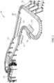
- an exemplary conveyor system 100 made in accordance with the present invention comprises a track 110, which includes a variety of turns and changes in elevation.
- the conveyor system 100 further includes multiple carts 400 that move along the track 110 and one or more feeder belts 120 that provide parcels onto the carts 400. The carts 400 then deposit these parcels into one or more sorter bins 130.
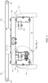
- an exemplary cart 400 includes a base 410 with a belt conveyor 440 connected to the top of the base 410.
- the belt conveyor including rollers 442 and a belt 444 which operate in a direction perpendicular to the direction of travel of the base 410 along the track 110.
- the conveyor 440 can readily accept parcels from the feeder belts 120 on either side of the cart 400 and deposit the parcels into the sorter bins 130 on either side of the cart 400.
- the cart 400 further includes vertical wheels 420 (shown only in FIG. 3 ) and horizontal wheels 430 which engage the track 110.
- the track 110 includes a first (or inner) rail 112 and a second (or outer) rail 114 which run parallel to one another.
- a first set of wheels 420, 430 engages the first rail 112 and a second set of wheels 420, 430 similarly engages the second rail 114.
- Each of the first and second rails 112, 114 is supported by a support frame 140, as discussed further below.
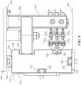
- the exemplary first rail 112 includes a top panel 210, a first (or inner) side panel 220, a second (or outer) side panel 230, and a bottom panel 240, such that the first rail 112 defines a substantially enclosed inner space.
- a vertical wheel 420 of the cart 400 is supported by the top panel 210 of the first rail 112, and a horizontal wheel 430 of the cart 400 engages the first side panel 220.
- the first side panel 220 defines a C-shaped first (or wheel) channel 224 within which the horizontal wheel 430 of the cart 400 is retained.
- the cart 400 is also electrically connected to the first rail 112.
- the cart 400 further includes an arm 450 that extends downward from the base 410 of the cart 400.
- At the end of the arm 450 are multiple (three) current collectors 452a, 452b, 452c which engage a respective connector rail 272a, 272b, 272c extending around the track 110.
- first side panel 220 of the first rail 112 further defines a second (or bolt) channel 222 that extends along the length of the first rail 112.
- a clamp 270 is secured to the first rail 112 by a bolt 260 within the bolt channel 222.
- Each of the multiple (three) connector rails 272a, 272b, 272c is thereby secured to the first rail 112 by the clamp 270.
- the connector rails 272a, 272b, 272c extend along substantially the entire length of the first rail 112 around the entirety of the track 110. Multiple clamps 270 are spaced along the length of the first rail 112 to adequately secure the connector rails 272a, 272b, 272c to the first rail 112.
- the clamps 270 are spaced about one meter (1 m) apart along the track 110.
- the particular spacing of the clamps 270 can be modified according to the particular configuration and requirements of the track 110. In this way, as the cart 400 moves around the track 110, the current collectors 452a, 452b, 452c of the cart 400 remain in contact with the connector rails 272a, 272b, 272c to thereby maintain electrical connection between electronic devices on the cart 400 and external electronic devices.
- the second side panel 230 and the bottom panel 240 each define a respective bolt channel 232, 242 that extends along the length of the first rail 112 (i.e., around the track 110).
- the bolt channels 232, 242 of the second side panel 230 and the bottom panel 240 are used to connect the first rail 112 to the support frame 140 of the conveyor system 100 with bolts 262, 264.
- the bolt channels 232, 242 of the second side panel 230 and the bottom panel 240 could also be used to attach other accessories (e.g., sensors or controllers) to the first rail 112.
- the bolt channels 232, 242 provide a connection point to the first rail 112 along the entire length of the track 110.
- the second rail 114 is substantially identical to the first rail 112, but a mirror image thereof.
- the first rail 112 includes the clamp 270 and plurality of connector rails 272a, 272b, 272c.
- the second rail 114 can also include a clamp and plurality of connector rails either instead of, or in addition to, the clamp 270 and plurality of connector rails 272a, 272b, 272c connected to the first rail 112.
- the exemplary rail 300 shown in FIG. 5 includes a first member 301a and a second member 301b.
- the first member 301a includes a first panel 302a, a second panel 304a opposite the first panel 302a, a third panel 306a that extends between the first panel 302a and the second panel 304a, and a fourth panel 308a that extends between the first panel 302a and the second panel 304a opposite from the third panel 306a.
- Each of the panels 302a, 304a, 306a, 308a is substantially flat, except the first panel 302a includes a projection 303a, and the fourth panel 308a defines a channel 309a, as discussed further below.
- the second member 301b similarly includes a first panel 302b with a projection 303b, a second panel 304b opposite the first panel 302b, a third panel 306b that extends between the first panel 302b and the second panel 304b, and a fourth panel 308b that extends between the first panel 302b and the second panel 304b opposite from the third panel 306b and which defines a channel 309b.
- the second member 301b is a mirror image of the first member 301a, and the first and second members 301a, 301b are connected to form the rail 300.
- the first panel 302b of the second member 301b is connected (e.g., welded) to the first panel 302a of the first member 301a to thereby form an intermediate panel 350 of the rail 300 that bifurcates the inner space of the rail 300.
- the projection 303a of the first panel 302a of the first member 301a and the projection 303b of the first panel 302b of the second member 301b facilitate in the welding of the first member 301a to the second member 301b.
- the second panel 304b of the second member 301b forms a top panel 310 of the rail 300 upon which a vertical wheel of the cart (not shown) is supported in substantially the same manner as the top panel 210 of the first rail 112 described above with respect to FIGS. 3 and 4 .
- the fourth panel 308a of the first member 301a and the fourth panel 308b of the second member 301b collectively form a first (or inner) side panel 320 of the rail 300 with the channel 309b of the fourth panel 308b of the second member 301b retaining a horizontal wheel of the cart (not shown) in substantially the same manner as the first side panel 220 of the first rail 112 described above with respect to FIGS. 3 and 4 .
- the rails 112, 114 shown in FIG. 3 are preferably used in straight sections of the track 110, whereas the rail 300 shown in FIG. 5 is preferably used in curved sections of the track 110.
- the overall shape of the rail 300 shown in FIG. 5 is designed to be substantially the same as the shape of the rails 112, 114 shown in FIG. 3 , such that a cart 400 can easily transition between those portions of the track 110 formed of the rails 112, 114 shown in FIG. 3 and those portions of the track 110 formed of the rail 300 shown in FIG. 5 .
- the intermediate panel 350 of the rail 300 shown in FIG. 5 increases the rigidity of the rail 300 as compared to the rails 112, 114 shown in FIG. 3 .
- This provides a greater bending radius for the rail 300 shown in FIG. 5 .
- the rail 300 shown in FIG. 5 has a bending diameter of about 4000 mm for horizontal turns in the track 110 and can provide an angle of inclination at elevation changes in the track 110 of about 12°.
- the rail 300 can therefore be used for any section of the track 110 including a horizontal curve, an elevation change, or where both a horizontal curve and elevation change occurs simultaneously on the track 110.
- the rails of the present invention are made of cold-rolled steel.
- the rails are made of stainless steel. This provides an improvement over aluminum rails which cause wear in the wheels of each cart at the point of contact between the wheels and the rail without also requiring any additional protection at this point of contact.
Landscapes
- Engineering & Computer Science (AREA)
- Mechanical Engineering (AREA)
- Handcart (AREA)
- Threshing Machine Elements (AREA)
- Platform Screen Doors And Railroad Systems (AREA)
- Framework For Endless Conveyors (AREA)
Claims (12)
- Fördersystem (100) mit einem Wagen (400), der sich entlang einer Schiene (112, 114) bewegt, wobei die Schiene aufweist:- eine obere Platte (210), auf der ein vertikales Rad (420) des Wagens (400) abgestützt wird;- eine erste Seitenplatte (220), die einen C-förmigen Kanal (224) bildet, in dem ein horizontales Rad (430) des Wagens (400) gehalten wird; und- eine oder mehrere Verbindungsschienen (272a, 272b, 272c), die sich entlang der Schiene (112, 114) erstrecken, wobei der Wagen elektrisch mit der einen oder den mehreren Verbindungsschienen verbunden ist.
- Fördersystem (100) nach Anspruch 1, wobei die erste Seitenplatte (220) ferner einen zweiten Kanal (222) bildet, und wobei mehrere Klemmen (270) innerhalb des zweiten Kanals positioniert sind, wobei die eine oder mehrere Verbindungsschienen (272a, 272b, 272c) durch mehrere Klemmen an der Schiene (112, 114) befestigt sind.
- Fördersystem (100) nach Anspruch 1, wobei die Schiene (112, 114) ferner eine Bodenplatte (240) gegenüber der oberen Platte (210) und eine zweite Seitenplatte (230) gegenüber der ersten Seitenplatte (220) umfasst, so dass die Schiene (112, 114) einen im Wesentlichen geschlossenen Innenraum bildet.
- Fördersystem (100) nach Anspruch 3, wobei die Bodenplatte (240) einen Bolzenkanal (242) bildet, der sich entlang der Länge der Schiene (112, 114) erstreckt, um die Schiene (112, 114) mit einem Tragrahmen (140) des Fördersystems mit Bolzen (262, 264) zu verbinden, die zweite Seitenplatte (230) einen Bolzenkanal (232) bildet, der sich entlang der Länge der Schiene (112, 114) erstreckt, um die Schiene (112, 114) mit einem Tragrahmen (140) des Fördersystems mit Bolzen (262, 264) zu verbinden, oder sowohl die Bodenplatte (240) als auch die zweite Seitenplatte (230) jeweils einen Bolzenkanal (242, 232) bilden, der sich entlang der Länge der Schiene (112, 114) erstreckt, um die Schiene (112, 114) mit einem Tragrahmen (140) des Fördersystems mit Bolzen (262, 264) zu verbinden.
- Fördersystem (100) nach Anspruch 3, das ferner eine Zwischenplatte (350) aufweist, die sich zwischen der ersten Seitenplatte (220) und der zweiten Seitenplatte (230) erstreckt, um den Innenraum gabelförmig zu teilen.
- Fördersystem (100) mit einem Wagen (400), der sich entlang einer Schiene (300) bewegt, wobei die Schiene (300) aufweist:- ein erstes Element (301a), umfassend:- eine erste Platte (302a),- eine zweite Platte (304a) gegenüber der ersten Platte (302a),- eine dritte Platte (306a), die sich zwischen der ersten Platte (302a) und der zweiten Platte (304a) erstreckt, und- eine vierte Platte (308a), die sich zwischen der ersten Platte (302a) und der zweiten Platte (304a) gegenüber der dritten Platte (306a) erstreckt, wobei die vierte Platte (308a) einen Kanal (309a) bildet; und- ein zweites Element (301b), umfassend:- eine erste Platte (302b),- eine zweite Platte (304b) gegenüber der ersten Platte (302b),- eine dritte Platte (306b), die sich zwischen der ersten Platte (302b) und der zweiten Platte (304b) erstreckt, und- eine vierte Platte (308b), die sich zwischen der ersten Platte (302b) und der zweiten Platte (304b) erstreckt, wobei die vierte Platte (308b) einen Kanal (309b) bildet;- wobei die erste Platte (302b) des zweiten Elements (301b) mit der ersten Platte (302a) des ersten Elements (301a) verbunden ist, so dass (a) die zweite Platte (304b) des zweiten Elements (301b) eine obere Platte (310) der Schiene (300) bildet, auf der ein vertikales Rad des Wagens (400) abgestützt wird, (b) die vierte Platte (308a) des ersten Elements (301a) und die vierte Platte (308b) des zweiten Elements (301b) zusammen eine erste Seitenplatte (320) der Schiene (300) bilden, und (c) ein horizontales Rad des Wagens (400) innerhalb des Kanals (309b) gehalten wird, der durch die vierte Platte (308b) des zweiten Elements (301b) gebildet wird.
- Fördersystem (100) nach Anspruch 6, wobei das zweite Element (301b) im Wesentlichen ein Spiegelbild des ersten Elements (301a) ist.
- Fördersystem (100) nach Anspruch 6, wobei die erste Platte (302a) des ersten Elements (301a) einen Vorsprung (303a) umfasst, die erste Platte (302b) des zweiten Elements (301b) einen Vorsprung (303b) umfasst und der Vorsprung (303a) des ersten Elements mit dem Vorsprung (303b) des zweiten Elements verbunden ist.
- Fördersystem (100) nach Anspruch 6, wobei die erste Platte (302b) des zweiten Elements (301b) mit der ersten Platte (302a) des ersten Elements (301a) verschweißt ist.
- Fördersystem (100) mit einem Wagen (400) und einer Schiene (110), die eine innere (112) und eine äußere Schiene (114) umfasst, wobei der Wagen (400) angepasst ist, um sich entlang der Schiene (110) zu bewegen, wobei sowohl die innere Schiene (12) als auch die äußere Schiene (114) aufweisen:- eine obere Platte (210);- eine untere Platte (240) gegenüber der oberen Platte (210);- eine innere Seitenplatte (220), die einen C-förmigen Kanal (224) bildet; und- eine äußere Seitenplatte (230), so dass sowohl die innere Schiene (112) als auch die äußere Schiene (114) einen im Wesentlichen geschlossenen Innenraum bilden;wobei die obere Platte (210) sowohl der inneren Schiene (112) als auch der äußeren Schiene (114) ein vertikales Rad (420) des Wagens (400) abstützt und der C-förmige Kanal (224) der inneren Seitenplatte (220) ein horizontales Rad (430) des Wagens (400) hält.
- Fördersystem (100) nach Anspruch 10, wobei die innere Seitenplatte (220) der inneren Schiene (112), die innere Seitenplatte (220) der äußeren Schiene (114) oder sowohl die innere Seitenplatte der inneren Schiene als auch die innere Seitenplatte der äußeren Schiene ferner einen zweiten Kanal (222) bilden; und wobei mehrere Klemmen (270) innerhalb des zweiten Kanals (222) positioniert sind, eine oder mehrere Verbindungsschienen (272a; 272b, 272c) durch mehrere Klemmen (270) an der Schiene (112, 114) befestigt sind und der Wagen (400) elektrisch mit der einen oder mehreren Verbindungsschienen verbunden ist.
- Fördersystem (100) nach Anspruch 10, wobei die innere Schiene (112), die äußere Schiene (114) oder sowohl die innere Schiene als auch die äußere Schiene ferner eine Zwischenplatte (350) aufweisen, die sich zwischen der inneren Seitenplatte und der äußeren Seitenplatte erstreckt, um den Innenraum gabelförmig zu teilen.
Applications Claiming Priority (2)
| Application Number | Priority Date | Filing Date | Title |
|---|---|---|---|
| IT102019000017438A IT201900017438A1 (it) | 2019-09-27 | 2019-09-27 | Sistema di trasporto |
| PCT/EP2020/077001 WO2021058799A1 (en) | 2019-09-27 | 2020-09-25 | Conveyor system |
Publications (3)
| Publication Number | Publication Date |
|---|---|
| EP4034484A1 EP4034484A1 (de) | 2022-08-03 |
| EP4034484C0 EP4034484C0 (de) | 2024-09-04 |
| EP4034484B1 true EP4034484B1 (de) | 2024-09-04 |
Family
ID=69173341
Family Applications (1)
| Application Number | Title | Priority Date | Filing Date |
|---|---|---|---|
| EP20775362.5A Active EP4034484B1 (de) | 2019-09-27 | 2020-09-25 | Fördersystem |
Country Status (8)
| Country | Link |
|---|---|
| US (1) | US11807474B2 (de) |
| EP (1) | EP4034484B1 (de) |
| CN (1) | CN114616194A (de) |
| CA (1) | CA3155145A1 (de) |
| ES (1) | ES2991035T3 (de) |
| IT (1) | IT201900017438A1 (de) |
| MX (1) | MX2022003674A (de) |
| WO (1) | WO2021058799A1 (de) |
Families Citing this family (1)
| Publication number | Priority date | Publication date | Assignee | Title |
|---|---|---|---|---|
| JP7770859B2 (ja) * | 2021-10-19 | 2025-11-17 | 株式会社東芝 | 物流ソータ用トレイ、及び、物品区分装置 |
Citations (1)
| Publication number | Priority date | Publication date | Assignee | Title |
|---|---|---|---|---|
| US7284654B2 (en) * | 2003-03-03 | 2007-10-23 | Dematic S.R.L. | Sorting conveyor provided with tilting bowls |
Family Cites Families (18)
| Publication number | Priority date | Publication date | Assignee | Title |
|---|---|---|---|---|
| US361340A (en) * | 1887-04-19 | Chaeles o | ||
| US3977513A (en) * | 1974-05-28 | 1976-08-31 | Sun Chemical Corporation | Cart conveyor system |
| IT8420722U1 (it) * | 1984-02-03 | 1985-08-03 | Canziani Francesco | Carrello in particolare per smistatrici con piattello ribaltabile ad azionamento autonomo |
| EP0361340B1 (de) * | 1988-09-26 | 1994-01-19 | FATA AUTOMATION S.p.A. | Fördersystem zum Bewegen von Material und Halbzeug |
| NL9100108A (nl) * | 1991-01-23 | 1992-08-17 | Promech Sorting Syst | Transport- en verdeelinstallatie. |
| US5297483A (en) * | 1992-10-28 | 1994-03-29 | Mitsubishi Jidosha Kogyo Kabushiki Kaisha | Work conveyor |
| IT237284Y1 (it) * | 1995-11-16 | 2000-09-05 | Cml Handling Technology S P A | Carrello per impianti di smisatmento,con piano di trasportoposizionabile su piu' livelli |
| US6206170B1 (en) * | 1996-04-15 | 2001-03-27 | Mantissa Corporation | Control system for a tilt tray sorter |
| US6571933B1 (en) * | 1998-10-20 | 2003-06-03 | Crisplant A/S | Inductive energy transfer system |
| DE202008009280U1 (de) * | 2008-07-10 | 2008-09-11 | Beumer Gmbh & Co. Kg | Fördervorrichtung mit entgegen der Verfahrrichtung antreibbarer Abschiebeeinrichtung |
| WO2013112561A1 (en) * | 2012-01-23 | 2013-08-01 | Cross Belt Ip, Llc | Monorail sortation system |
| CN102808948B (zh) * | 2012-08-15 | 2015-06-17 | 高彦 | 用于封闭运料小车横梁与车体凹槽间缝隙的密封装置 |
| US9409716B2 (en) * | 2014-06-13 | 2016-08-09 | Bastian Solutions, Llc | Cross belt slat sorter |
| US10207867B2 (en) * | 2015-07-01 | 2019-02-19 | Swisslog Logistics, Inc. | Automated pallet storage and retrieval system |
| WO2017162144A1 (zh) * | 2016-03-23 | 2017-09-28 | 刘忠臣 | 永磁悬浮列车轨道系统 |
| CA2937669C (en) * | 2016-07-29 | 2024-06-11 | Swisslog Logistics, Inc. | Automated pallet storage and retrieval system |
| JP6848373B2 (ja) * | 2016-11-14 | 2021-03-24 | 株式会社ダイフク | 物品搬送設備 |
| CN108311398A (zh) * | 2018-02-13 | 2018-07-24 | 威海新北洋正棋机器人股份有限公司 | 一种轨道环线及交叉带分拣机 |
-
2019
- 2019-09-27 IT IT102019000017438A patent/IT201900017438A1/it unknown
-
2020
- 2020-09-25 MX MX2022003674A patent/MX2022003674A/es unknown
- 2020-09-25 EP EP20775362.5A patent/EP4034484B1/de active Active
- 2020-09-25 ES ES20775362T patent/ES2991035T3/es active Active
- 2020-09-25 WO PCT/EP2020/077001 patent/WO2021058799A1/en not_active Ceased
- 2020-09-25 CA CA3155145A patent/CA3155145A1/en active Pending
- 2020-09-25 CN CN202080067595.6A patent/CN114616194A/zh active Pending
- 2020-09-25 US US17/760,918 patent/US11807474B2/en active Active
Patent Citations (1)
| Publication number | Priority date | Publication date | Assignee | Title |
|---|---|---|---|---|
| US7284654B2 (en) * | 2003-03-03 | 2007-10-23 | Dematic S.R.L. | Sorting conveyor provided with tilting bowls |
Also Published As
| Publication number | Publication date |
|---|---|
| WO2021058799A1 (en) | 2021-04-01 |
| US20220340378A1 (en) | 2022-10-27 |
| EP4034484A1 (de) | 2022-08-03 |
| CN114616194A (zh) | 2022-06-10 |
| IT201900017438A1 (it) | 2021-03-27 |
| MX2022003674A (es) | 2022-06-08 |
| ES2991035T3 (es) | 2024-12-02 |
| CA3155145A1 (en) | 2021-04-01 |
| US11807474B2 (en) | 2023-11-07 |
| EP4034484C0 (de) | 2024-09-04 |
Similar Documents
| Publication | Publication Date | Title |
|---|---|---|
| US7789019B2 (en) | Overhead traveling vehicle system and construction method of buffer in the system | |
| US10359234B2 (en) | Temperature control device for controlling the temperature of workpieces | |
| US6935490B2 (en) | Conveying installation for transporting goods | |
| EP4034484B1 (de) | Fördersystem | |
| JP5163866B2 (ja) | 天井バッファとその移設方法 | |
| EP3130552B1 (de) | Hybridtransportsystem für objekte | |
| CN103434808B (zh) | 一种钢管运输方法 | |
| US20150259159A1 (en) | Method and Device for Turning Large-Area Panels in Extreme Oversize | |
| EP3539903A1 (de) | Deckenfördersystem und relaisfördervorrichtung und förderverfahren dafür | |
| EP3581456A3 (de) | Kabeltransportsystem | |
| JP7147735B2 (ja) | 走行レール、及び、物品搬送設備 | |
| JP6693428B2 (ja) | 物品搬送車 | |
| US10202050B2 (en) | Power rail-support unit and guide-track transportation system | |
| CN210149642U (zh) | 一种简易高效的转向结构 | |
| SE541308C2 (en) | Adjustable antenna mounting system | |
| JP6590544B2 (ja) | 蓄電池車両の充電所用架線構造 | |
| CN107600942B (zh) | 线夹搬运装置 | |
| JPH04304110A (ja) | レール装置 | |
| CN208051265U (zh) | 空调蒸发器焊接工装 | |
| JPH04265302A (ja) | 搬送装置のレール取り付け構造 | |
| FR3068682B1 (fr) | Systeme d'acheminement de charges entre une pluralite d'unites de stockage et une pluralite de postes de preparation, via un reseau de drainage de charges reparti sur deux plans horizontaux | |
| RO201700033U1 (ro) | Canal pentru cabluri şi conducte | |
| NZ194822A (en) | Jaw for supporting trolley-bus overhead wires | |
| JP2012116255A (ja) | 絶縁トロリ及びその集電装置 | |
| JPH03164362A (ja) | 搬送装置のレール取付け構造 |
Legal Events
| Date | Code | Title | Description |
|---|---|---|---|
| STAA | Information on the status of an ep patent application or granted ep patent |
Free format text: STATUS: UNKNOWN |
|
| STAA | Information on the status of an ep patent application or granted ep patent |
Free format text: STATUS: THE INTERNATIONAL PUBLICATION HAS BEEN MADE |
|
| PUAI | Public reference made under article 153(3) epc to a published international application that has entered the european phase |
Free format text: ORIGINAL CODE: 0009012 |
|
| STAA | Information on the status of an ep patent application or granted ep patent |
Free format text: STATUS: REQUEST FOR EXAMINATION WAS MADE |
|
| 17P | Request for examination filed |
Effective date: 20220414 |
|
| AK | Designated contracting states |
Kind code of ref document: A1 Designated state(s): AL AT BE BG CH CY CZ DE DK EE ES FI FR GB GR HR HU IE IS IT LI LT LU LV MC MK MT NL NO PL PT RO RS SE SI SK SM TR |
|
| DAV | Request for validation of the european patent (deleted) | ||
| DAX | Request for extension of the european patent (deleted) | ||
| RAP1 | Party data changed (applicant data changed or rights of an application transferred) |
Owner name: MATERIAL HANDLING SYSTEMS, INC. |
|
| GRAP | Despatch of communication of intention to grant a patent |
Free format text: ORIGINAL CODE: EPIDOSNIGR1 |
|
| STAA | Information on the status of an ep patent application or granted ep patent |
Free format text: STATUS: GRANT OF PATENT IS INTENDED |
|
| INTG | Intention to grant announced |
Effective date: 20240408 |
|
| GRAS | Grant fee paid |
Free format text: ORIGINAL CODE: EPIDOSNIGR3 |
|
| GRAA | (expected) grant |
Free format text: ORIGINAL CODE: 0009210 |
|
| STAA | Information on the status of an ep patent application or granted ep patent |
Free format text: STATUS: THE PATENT HAS BEEN GRANTED |
|
| AK | Designated contracting states |
Kind code of ref document: B1 Designated state(s): AL AT BE BG CH CY CZ DE DK EE ES FI FR GB GR HR HU IE IS IT LI LT LU LV MC MK MT NL NO PL PT RO RS SE SI SK SM TR |
|
| REG | Reference to a national code |
Ref country code: GB Ref legal event code: FG4D |
|
| REG | Reference to a national code |
Ref country code: CH Ref legal event code: EP |
|
| REG | Reference to a national code |
Ref country code: IE Ref legal event code: FG4D |
|
| REG | Reference to a national code |
Ref country code: DE Ref legal event code: R096 Ref document number: 602020037156 Country of ref document: DE |
|
| U01 | Request for unitary effect filed |
Effective date: 20240925 |
|
| U07 | Unitary effect registered |
Designated state(s): AT BE BG DE DK EE FI FR IT LT LU LV MT NL PT RO SE SI Effective date: 20241018 |
|
| U20 | Renewal fee for the european patent with unitary effect paid |
Year of fee payment: 5 Effective date: 20241018 |
|
| REG | Reference to a national code |
Ref country code: ES Ref legal event code: FG2A Ref document number: 2991035 Country of ref document: ES Kind code of ref document: T3 Effective date: 20241202 |
|
| PG25 | Lapsed in a contracting state [announced via postgrant information from national office to epo] |
Ref country code: NO Free format text: LAPSE BECAUSE OF FAILURE TO SUBMIT A TRANSLATION OF THE DESCRIPTION OR TO PAY THE FEE WITHIN THE PRESCRIBED TIME-LIMIT Effective date: 20241204 |
|
| RAP4 | Party data changed (patent owner data changed or rights of a patent transferred) |
Owner name: FORTNA SYSTEMS, INC. |
|
| U1H | Name or address of the proprietor changed after the registration of the unitary effect |
Owner name: FORTNA SYSTEMS, INC.; US |
|
| PG25 | Lapsed in a contracting state [announced via postgrant information from national office to epo] |
Ref country code: PL Free format text: LAPSE BECAUSE OF FAILURE TO SUBMIT A TRANSLATION OF THE DESCRIPTION OR TO PAY THE FEE WITHIN THE PRESCRIBED TIME-LIMIT Effective date: 20240904 Ref country code: GR Free format text: LAPSE BECAUSE OF FAILURE TO SUBMIT A TRANSLATION OF THE DESCRIPTION OR TO PAY THE FEE WITHIN THE PRESCRIBED TIME-LIMIT Effective date: 20241205 |
|
| PG25 | Lapsed in a contracting state [announced via postgrant information from national office to epo] |
Ref country code: HR Free format text: LAPSE BECAUSE OF FAILURE TO SUBMIT A TRANSLATION OF THE DESCRIPTION OR TO PAY THE FEE WITHIN THE PRESCRIBED TIME-LIMIT Effective date: 20240904 |
|
| PG25 | Lapsed in a contracting state [announced via postgrant information from national office to epo] |
Ref country code: RS Free format text: LAPSE BECAUSE OF FAILURE TO SUBMIT A TRANSLATION OF THE DESCRIPTION OR TO PAY THE FEE WITHIN THE PRESCRIBED TIME-LIMIT Effective date: 20241204 |
|
| PGFP | Annual fee paid to national office [announced via postgrant information from national office to epo] |
Ref country code: ES Payment date: 20241028 Year of fee payment: 5 |
|
| PG25 | Lapsed in a contracting state [announced via postgrant information from national office to epo] |
Ref country code: RS Free format text: LAPSE BECAUSE OF FAILURE TO SUBMIT A TRANSLATION OF THE DESCRIPTION OR TO PAY THE FEE WITHIN THE PRESCRIBED TIME-LIMIT Effective date: 20241204 Ref country code: PL Free format text: LAPSE BECAUSE OF FAILURE TO SUBMIT A TRANSLATION OF THE DESCRIPTION OR TO PAY THE FEE WITHIN THE PRESCRIBED TIME-LIMIT Effective date: 20240904 Ref country code: NO Free format text: LAPSE BECAUSE OF FAILURE TO SUBMIT A TRANSLATION OF THE DESCRIPTION OR TO PAY THE FEE WITHIN THE PRESCRIBED TIME-LIMIT Effective date: 20241204 Ref country code: HR Free format text: LAPSE BECAUSE OF FAILURE TO SUBMIT A TRANSLATION OF THE DESCRIPTION OR TO PAY THE FEE WITHIN THE PRESCRIBED TIME-LIMIT Effective date: 20240904 Ref country code: GR Free format text: LAPSE BECAUSE OF FAILURE TO SUBMIT A TRANSLATION OF THE DESCRIPTION OR TO PAY THE FEE WITHIN THE PRESCRIBED TIME-LIMIT Effective date: 20241205 |
|
| PG25 | Lapsed in a contracting state [announced via postgrant information from national office to epo] |
Ref country code: IS Free format text: LAPSE BECAUSE OF FAILURE TO SUBMIT A TRANSLATION OF THE DESCRIPTION OR TO PAY THE FEE WITHIN THE PRESCRIBED TIME-LIMIT Effective date: 20250104 |
|
| PG25 | Lapsed in a contracting state [announced via postgrant information from national office to epo] |
Ref country code: SM Free format text: LAPSE BECAUSE OF FAILURE TO SUBMIT A TRANSLATION OF THE DESCRIPTION OR TO PAY THE FEE WITHIN THE PRESCRIBED TIME-LIMIT Effective date: 20240904 |
|
| PG25 | Lapsed in a contracting state [announced via postgrant information from national office to epo] |
Ref country code: CZ Free format text: LAPSE BECAUSE OF FAILURE TO SUBMIT A TRANSLATION OF THE DESCRIPTION OR TO PAY THE FEE WITHIN THE PRESCRIBED TIME-LIMIT Effective date: 20240904 |
|
| PG25 | Lapsed in a contracting state [announced via postgrant information from national office to epo] |
Ref country code: SK Free format text: LAPSE BECAUSE OF FAILURE TO SUBMIT A TRANSLATION OF THE DESCRIPTION OR TO PAY THE FEE WITHIN THE PRESCRIBED TIME-LIMIT Effective date: 20240904 |
|
| REG | Reference to a national code |
Ref country code: CH Ref legal event code: PL |
|
| PG25 | Lapsed in a contracting state [announced via postgrant information from national office to epo] |
Ref country code: MC Free format text: LAPSE BECAUSE OF FAILURE TO SUBMIT A TRANSLATION OF THE DESCRIPTION OR TO PAY THE FEE WITHIN THE PRESCRIBED TIME-LIMIT Effective date: 20240904 |
|
| PLBE | No opposition filed within time limit |
Free format text: ORIGINAL CODE: 0009261 |
|
| STAA | Information on the status of an ep patent application or granted ep patent |
Free format text: STATUS: NO OPPOSITION FILED WITHIN TIME LIMIT |
|
| PG25 | Lapsed in a contracting state [announced via postgrant information from national office to epo] |
Ref country code: CH Free format text: LAPSE BECAUSE OF NON-PAYMENT OF DUE FEES Effective date: 20240930 |
|
| PG25 | Lapsed in a contracting state [announced via postgrant information from national office to epo] |
Ref country code: IE Free format text: LAPSE BECAUSE OF NON-PAYMENT OF DUE FEES Effective date: 20240925 |
|
| 26N | No opposition filed |
Effective date: 20250605 |
|
| PGFP | Annual fee paid to national office [announced via postgrant information from national office to epo] |
Ref country code: GB Payment date: 20250929 Year of fee payment: 6 |
|
| U20 | Renewal fee for the european patent with unitary effect paid |
Year of fee payment: 6 Effective date: 20250929 |