EP4025443B1 - Profilleiste mit einem wasserableitenden element - Google Patents
Profilleiste mit einem wasserableitenden element Download PDFInfo
- Publication number
- EP4025443B1 EP4025443B1 EP21819335.7A EP21819335A EP4025443B1 EP 4025443 B1 EP4025443 B1 EP 4025443B1 EP 21819335 A EP21819335 A EP 21819335A EP 4025443 B1 EP4025443 B1 EP 4025443B1
- Authority
- EP
- European Patent Office
- Prior art keywords
- latching
- water
- region
- windscreen
- profile strip
- Prior art date
- Legal status (The legal status is an assumption and is not a legal conclusion. Google has not performed a legal analysis and makes no representation as to the accuracy of the status listed.)
- Active
Links
Images



Classifications
-
- B—PERFORMING OPERATIONS; TRANSPORTING
- B62—LAND VEHICLES FOR TRAVELLING OTHERWISE THAN ON RAILS
- B62D—MOTOR VEHICLES; TRAILERS
- B62D25/00—Superstructure or monocoque structure sub-units; Parts or details thereof not otherwise provided for
- B62D25/08—Front or rear portions
- B62D25/081—Cowls
-
- B—PERFORMING OPERATIONS; TRANSPORTING
- B60—VEHICLES IN GENERAL
- B60J—WINDOWS, WINDSCREENS, NON-FIXED ROOFS, DOORS, OR SIMILAR DEVICES FOR VEHICLES; REMOVABLE EXTERNAL PROTECTIVE COVERINGS SPECIALLY ADAPTED FOR VEHICLES
- B60J10/00—Sealing arrangements
- B60J10/20—Sealing arrangements characterised by the shape
- B60J10/25—Sealing arrangements characterised by the shape characterised by water drainage means
-
- B—PERFORMING OPERATIONS; TRANSPORTING
- B60—VEHICLES IN GENERAL
- B60J—WINDOWS, WINDSCREENS, NON-FIXED ROOFS, DOORS, OR SIMILAR DEVICES FOR VEHICLES; REMOVABLE EXTERNAL PROTECTIVE COVERINGS SPECIALLY ADAPTED FOR VEHICLES
- B60J10/00—Sealing arrangements
- B60J10/30—Sealing arrangements characterised by the fastening means
- B60J10/32—Sealing arrangements characterised by the fastening means using integral U-shaped retainers
-
- B—PERFORMING OPERATIONS; TRANSPORTING
- B60—VEHICLES IN GENERAL
- B60J—WINDOWS, WINDSCREENS, NON-FIXED ROOFS, DOORS, OR SIMILAR DEVICES FOR VEHICLES; REMOVABLE EXTERNAL PROTECTIVE COVERINGS SPECIALLY ADAPTED FOR VEHICLES
- B60J10/00—Sealing arrangements
- B60J10/70—Sealing arrangements specially adapted for windows or windscreens
Definitions
- the present invention relates to a profile strip with a water-draining element for guiding and for the controlled drainage of water that occurs on an outside of the profile strip or in a latching area of the profile strip.
- Such moldings are attached to a lower edge of a windshield, which is then installed in the vehicle body.
- water running off the A-pillar such as rainwater
- the font EP 3 256 339 B1 Provides a hole in the fastening area of a water box profile to drain off water penetrating between the pane and the profile strip. However, this does not prevent uncontrolled dripping of water from the outside of the profile.
- the font FR 3 094 282 A1 provides a drainage channel, which is also provided in the rest area in the direction of the water box cover.
- the font EP1 571 069 A1 discloses an adjustment and guiding device in the form of clips, which are provided on a profile strip in order to provide guidance for a rib of the water tank cover in the latching area of the profile strip during assembly of a water tank cover.
- the font U.S. 2010/0194150 A1 discloses a profile strip for sealing a movable pane of a motor vehicle.
- the known profile strips do not lead to controlled dripping of water present on the outside or in the latching area of a profile strip.
- the technical problem consists in providing a solution for the controlled directing or draining of water from the resting area or from the outside of a molding.
- a profile strip comprising a water-draining element according to the characterizing part of one of claims 1 to 3 or 5.
- the aim of the invention is therefore the guidance and/or drainage of water occurring in the resting area and on the outside of a profile strip.
- a profile strip for connecting a windshield of a motor vehicle to a water tank cover comprising a fastening area which can be connected to the windshield and has a fastening side facing the windshield and an underside facing away from the windshield, and comprising a latching region with a latching groove for latching Accommodating a rib of the water tank cover and having an outside facing away from the latching groove, the latching groove being delimited by an inner leg adjacent to the fastening area, an outer leg opposite the inner leg and a base section connecting the two legs, the profile strip having a water-draining element, which is arranged in a partial section along a longitudinal extent of the profile strip on the latching area.
- a longitudinal extension of the partial section measured parallel to a longitudinal direction of the profile strip can be smaller than the longitudinal extension of the profile strip.
- the water-draining element is designed as an additional part arranged in the area of the subsection at least on a part of the outside of the latching area.
- the additional part is designed in such a way that, viewed in cross section, it encloses at least part of the latching area. Viewed in cross section, it can optionally also extend over at least part of the underside of the fastening area.
- the additional part has an essentially uniform cross-sectional profile along its longitudinal extent measured parallel to a longitudinal direction of the profile strip.
- the additional part can also have a variable cross-sectional profile along its longitudinal extension measured parallel to the longitudinal direction of the profile strip.
- the additional part can be formed at least partially from a preferably water-repellent or waterproof foam material.
- the additional part at least partially covers an opening provided in the base section and/or in the outer leg of the profile strip.
- a sealing element effective between the additional part and at least one part of a border delimiting the opening can optionally be provided.
- the additional part is arranged on a front end of the latching area on the profile strip, and viewed in cross section it at least partially covers the latching groove.
- the additional part optionally has a drain opening which is connected to the latching groove in a fluid-conducting manner.
- the water-draining element is designed as a drainage opening provided in the region of the partial section in the bottom section and/or in the outer leg.
- At least a partial area of a boundary delimiting the drainage opening has a drip edge that projects outwards in relation to the locking groove.
- the water-draining element is arranged as a material thickening in the area of the partial section on the outside of the latching area on the base section and/or on the outer leg and protrudes outwards in relation to the latching groove, or as a thickened portion on the base section and/or formed on the outer leg arranged and in relation to the locking groove recessed indentation.
- the water-draining element according to the invention can either be attached as an additional part on the outside of the profile strip or be an integral part of the profile strip and be formed, for example, by a local opening in the latching area or by local contouring of the outside of the latching area.
- the water-draining element is arranged in a partial section along the longitudinal extent of the profile strip on the latching area, the partial section preferably having a smaller longitudinal extent measured parallel to the longitudinal direction of the profile strip than the profile strip. This enables water to be drained off in a controlled manner at a desired point along the length of the profile strip. It can be a section or several sections can be provided on the same profile strip, even if the term section is only used in the singular below.
- a profile strip according to the invention for connecting a windshield of a motor vehicle and a water tank cover comprises, in a known manner, a fastening area and a latching area.
- a windshield can be connected to the fastening area of the profile strip on its fastening side by means of a fastening means, for example double-sided adhesive tape. Other types of attachment are also possible.
- the latching area includes a latching groove which extends in the longitudinal direction of the profile strip.
- the locking groove serves to accommodate a locking rib of the water tank cover.
- the latching groove is delimited by an inner leg in the direction of the fastening area. Opposite the inner leg is an outer leg. Between these two legs there is a bottom section which connects the two legs to one another and forms the latching groove together with them. In the case of a V-shaped locking groove, the bottom section represents the area where the inner and outer legs meet.
- a latching element for preferably latching engagement with the rib of the water tank cover can be located in the latching groove.
- the rib can also be latched by one or more undercuts on one or both legs.
- the fastening area and the latching area of the profile strip are preferably connected to one another in one piece.
- the profile strip preferably consists of a plastic and can preferably be produced in an extrusion process.
- the profile strip can contain reinforcements, preferably made of a metal or a metal alloy.
- the profile strip according to the invention also includes the water-draining element arranged in the partial section of the profile strip on the latching area, which is an in particular local contouring in the area of the outside of the latching area, a contouring in the bottom section and/or in the outer leg provided discharge opening or an additional part arranged on the latching area.
- the longitudinal extent of the partial section measured parallel to the longitudinal direction of the profile strip is preferably smaller than the longitudinal extent of the profile strip.
- the longitudinal extent of the partial section is preferably 10%, 5%, 3%, 2% and particularly preferably 1% of the longitudinal extent of the profile strip.
- the water-draining element is an additional part which is arranged in the area of the section of the profile strip at least on a part of the outside of the latching area of the profile strip and is preferably connected to the profile strip in a non-positive and/or positive manner.
- a cohesive or adhesive attachment is also conceivable. This allows the profile strip and the water-diverting element to be manufactured easily and separately in methods that can be optimized separately.
- the additional part is manufactured separately from the profile bar. After its manufacture, it is arranged on the profile strip, for example by means of clipping.
- the material of the additional part is preferably made of plastic and can be identical to a material of the profile strip.
- the plastic can also be different and, for example, harder or softer (higher or lower Shore hardness) than the plastic of the profile strip or part of it.
- the additional part encompasses at least a part of the outside of the latching area.
- the additional part can also extend over at least a part of the underside of the fastening area when viewed in cross section.
- Such an additional part for example in the form of a clip, can have an essentially uniform cross-sectional profile along its length.
- the diameter or the material thickness of the additional part is therefore essentially the same in the longitudinal direction.
- the longitudinal extent of the additional part designates its extent in a direction parallel to the longitudinal direction of the profile strip. This allows the additional part to be manufactured easily, for example by extrusion and subsequent separation into sections of the desired length.
- the additional part can have a variable cross-sectional profile along its length.
- Such an additional part then has different material thicknesses along its length.
- the detachment of water droplets can be forced in a selected area of the additional part, in which the contour is designed in such a way that, for example, a drip edge or a drip point is formed.
- the additional part can consist partially or completely of a preferably water-repellent or waterproof foam material.
- it can also be attached to the outside of the profile strip in a material-to-material manner.
- the foam material encloses at least part of the outside of the latching area.
- the foam material may also extend along part or all of the underside of the attachment area.
- the additional part can be arranged in the area of a local opening of the outer leg and/or the base section, wherein it at least partially encompasses the outside of the latching area viewed in cross section and at least partially, preferably essentially, covers the opening.
- a sealing element effective between the additional part and at least one part of a boundary delimiting the opening can be provided.
- the opening can be created by punching, drilling, milling, cutting or the like. This enables water present in the locking groove to be drained off in a controlled manner.
- the additional part can also be arranged on a front end of the latching area, ie in the area of an end of the profile strip delimiting the longitudinal extent of the profile strip.
- two of these additional parts can also be arranged on both front ends of the latching area.
- the additional part can be pushed onto the end, for example from the outside. This additional part is dimensioned in such a way that, viewed in cross section, it covers the latching groove at least partially, preferably completely.
- an outflow opening for example in the form of a socket or a grommet, which is connected to the latching groove in a fluid-conducting manner, can optionally be provided.
- a profile strip according to the invention can also include more than one of the additional parts described above.
- several additional parts of different embodiments can also be arranged on a profile strip according to the invention, for example one or two additional parts on one or both front ends of the latching area combined with one or more additional parts along the longitudinal extent of the profile strip.
- the use of an additional part does not exclude the use of a further additional part, but is left to the discretion of the person skilled in the art.
- the water-diverting element can also be an integral part of the profile strip. This eliminates additional elements that must be manufactured separately and attached to the profile bar.
- the water-draining element is designed as a drainage opening provided in the area of the partial section in the locking area, which opens the locking groove locally in this area.
- the drainage opening can be formed in the outer leg and/or in the base section.
- the drainage opening can be produced by punching, drilling, milling, cutting or the like. The drainage opening can be used both for the controlled drainage of water from the locking groove and for the controlled dripping of water running along the outside of the profile strip.
- At least one part of a border delimiting the drainage opening has a drip edge which projects outwards in relation to the locking groove.
- the drainage opening can be produced together with the projecting drip edge in a combined punching and flanging process.
- Appropriate dripping edges are preferably provided on two edge regions of the drainage opening that lie opposite one another in the longitudinal direction of the profiled strip.
- the water-draining element is a local material indentation or local material thickening provided in the area of the partial section of the profile strip on the outside of the latching area.
- a material thickening pointing outwards in relation to the locking groove can be provided on the outer leg and/or on the bottom section of the locking area.
- an indentation that is inwardly recessed in relation to the locking groove can be present on the outer leg and/or on the bottom section of the locking area. Contour edges of the material thickening or the indentation cause water to drip off in a controlled manner from the outside of the profile.
- the indentation or the thickening of the material can preferably be located at a lowest point of the profile strip when viewed in cross-section when installed.
- the installed state is given when the profile strip is attached to a windshield mounted in a vehicle. In this installed state, the profile strip is inclined. a in figure 1
- the cross section of the profile strip shown on the left is then rotated clockwise by 30°, for example.
- the lowest point of the profile, viewed in cross section is then in the area of the outer leg and/or in the area of the base section and/or in the transition area between the outer leg and the base section.
- a given profile strip has a number of partial sections whose longitudinal extension is in each case smaller than the longitudinal extension of the profile strip.
- the profile strip according to the invention comprising a water-draining element, is used to direct and/or drain off water occurring on or in the profile strip.
- This can, for example, be water that occurs on the outside of a profile strip or is present in the profile strip.
- method step a) can include the steps of providing a profile strip, providing the water-draining element in the form of an additional part, and arranging the water-draining element in the section of the profile strip and at least part of the outside of the locking area of the profile strip .
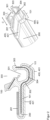
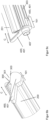
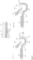
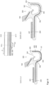
- the figures each show a profile strip (100) comprising a fastening area (200) with a fastening means (201) for connection to a windshield and a locking area (300) for locking connection to a water tank cover.
- the latching area (300) comprises a latching groove (301) extending in the longitudinal direction (C) of the profile strip (100) and into which a rib of the water tank cover can engage in a latching manner, the latching groove (301) being delimited by an inner leg (302), which is arranged adjacent to the fastening area (200), an outer leg (303) opposite the inner leg (302) and a bottom section (304) located between the two legs (302, 303).
- the profile strip (100) has a partial section (101) along its length.
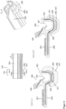
- the Figures 1 to 6b show water-draining elements (400) in the form of one arranged in the area of the partial section (101) on the profile strip (100). Additional part (401).
- the Figures 7 to 9 show water-draining elements (400) as an integral part of the profile strip (100) in the area of the respective section (101) of the profile strip (100).
- the figure 1 shows a water-draining element (400) arranged as an additional part (401) in the area of the section (101) of the profile strip (100) on the outside of the latching area (300) of the profile strip (100).
- the additional part (401) encompasses at least part of the outside of the latching area (300) and has a uniform cross-sectional profile along its length.
- the water-draining element (400) shown is also arranged as an additional part (401) in the area of the partial section (101) of the profile strip (100) on the outside of the profile strip (100).
- This additional part (401) has a uniform cross-sectional profile along its length and, viewed in cross section, extends along a part of the outside of the latching area (300) and additionally along the underside of the fastening area (200).
- the water-draining element (400) shown is arranged as an additional part (401) in the area of the partial section (101) on the outside of the locking area (300) of the profile strip (100) and, seen in cross section, encompasses at least part of the outside of the locking area (300).
- This additional part (401) has a variable cross-sectional profile along its length.
- the additional part (401) has in cross section according to figure 3 , Section AA, has a higher material thickness than in the cross-section according to figure 3 , cut BB.
- a water-diverting element (400) is shown in the form of an additional part (401), which is formed from a preferably water-repellent or waterproof foam material (402). Viewed in cross section, it extends both along part of the outside of the latching area (300) and along part of the underside of the fastening area (200).
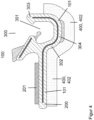
- a water-draining element (400) in the form of an additional part (401) covering a local opening (305) in the latching area (300) is shown.
- the additional part (401) also has a drain opening (407) which is fluid-conductingly connected to the locking groove. This serves to additionally drain off any liquid present in the locking groove (301).
- a seal can optionally be present, which essentially surrounds the opening (305) after the additional part (401) has been installed.
- the Figures 6a to 6c show a water-draining element (400) in the form of an additional part (401 ).
- the additional part (401) viewed in cross section, extends both along a part of the outside of the locking area (300) and along the underside of the fastening area (200) and thus prevents water from penetrating the locking groove (301).
- the additional part (401) can also have a drain opening (407) that is fluidly connected to the latching groove.
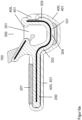
- the Figures 7a and 7b show a water-draining element (400) as an integral part of the profile strip (100) in the area of the section (101).
- the outer leg (303) has a water-draining element (400) in the form of a drainage opening (403) in the area of the section (101).
- This drainage opening (403) is formed in the outer leg (303) and a part of the bottom section (304).
- dripping edges (404) which are oriented transversely to the longitudinal direction (C) and which are opposite in the longitudinal direction (C) of the profile strip (100).
- the drip edges (404) project outwards in relation to the locking groove (301) and allow the water to drip off in a controlled manner at this point on the profile strip (100).
- a water-draining element (400) not according to the invention is shown in the area of the partial section (101) in the form of a material thickening (405) pointing outwards in relation to the locking groove (301) on the outside of the locking area (300).
- the thickening of the material concerns (405), as shown in section AA, the outer leg (303), the inner leg (302) and the bottom portion (304).
- This thickening (405) is only provided in an area of the latching area (300) of the profile strip (100) that forms the water-diverting element (400), while the profile strip (100) has a cross-sectional profile shown in section BB outside this area.
- FIG 9 shows a non-inventive water-draining element (400) in the area of the partial section (101) in the form of an inwardly recessed indentation (406) in relation to the locking groove (301) on the outside of the locking area (300).
- the indentation (406) relates to the outer leg (303), the inner leg (302) and the bottom section (304) and is only provided in an area of the latching area (300) of the profile strip (100) that forms the water-diverting element (400) ( cf. section AA), while the profile bar (100) outside of this area has a cross-sectional profile shown in section BB.
Landscapes
- Engineering & Computer Science (AREA)
- Mechanical Engineering (AREA)
- Chemical & Material Sciences (AREA)
- Combustion & Propulsion (AREA)
- Transportation (AREA)
- Seal Device For Vehicle (AREA)
- Body Structure For Vehicles (AREA)
- Structures Of Non-Positive Displacement Pumps (AREA)
- Connection Of Plates (AREA)
- Diaphragms For Electromechanical Transducers (AREA)
Applications Claiming Priority (2)
| Application Number | Priority Date | Filing Date | Title |
|---|---|---|---|
| DE102020131603.8A DE102020131603A1 (de) | 2020-11-30 | 2020-11-30 | Profilleiste mit einem wasserableitenden Element |
| PCT/DE2021/100925 WO2022111760A1 (de) | 2020-11-30 | 2021-11-23 | Profilleiste mit einem wasserableitenden element |
Publications (2)
| Publication Number | Publication Date |
|---|---|
| EP4025443A1 EP4025443A1 (de) | 2022-07-13 |
| EP4025443B1 true EP4025443B1 (de) | 2023-03-01 |
Family
ID=78821257
Family Applications (1)
| Application Number | Title | Priority Date | Filing Date |
|---|---|---|---|
| EP21819335.7A Active EP4025443B1 (de) | 2020-11-30 | 2021-11-23 | Profilleiste mit einem wasserableitenden element |
Country Status (10)
| Country | Link |
|---|---|
| US (1) | US12570361B2 (enExample) |
| EP (1) | EP4025443B1 (enExample) |
| JP (1) | JP7692470B2 (enExample) |
| CN (1) | CN116568540B (enExample) |
| DE (1) | DE102020131603A1 (enExample) |
| ES (1) | ES2945871T3 (enExample) |
| MA (1) | MA59653B1 (enExample) |
| MX (1) | MX2023006283A (enExample) |
| PL (1) | PL4025443T3 (enExample) |
| WO (1) | WO2022111760A1 (enExample) |
Families Citing this family (1)
| Publication number | Priority date | Publication date | Assignee | Title |
|---|---|---|---|---|
| DE102022113667B4 (de) | 2022-05-31 | 2025-08-07 | Elkamet Kunststofftechnik Gmbh | Profilleistenanordnung umfassend eine Profilleiste und ein Funktionselement |
Family Cites Families (16)
| Publication number | Priority date | Publication date | Assignee | Title |
|---|---|---|---|---|
| JPS5867518A (ja) * | 1981-10-20 | 1983-04-22 | Kinugawa Rubber Ind Co Ltd | ウインドウエザ−ストリツプ |
| US4892351A (en) * | 1987-03-13 | 1990-01-09 | Honda Giken Kogyo K.K. | Water drain trough for automotive sunroof |
| JP2001090979A (ja) * | 1999-09-22 | 2001-04-03 | Sanyo Electric Co Ltd | 空気調和機の室内ユニット用ドレンホース |
| DE20008555U1 (de) * | 2000-05-12 | 2000-08-17 | Elkamet Kunststofftechnik GmbH, 35216 Biedenkopf | Abdichtungs-Anordnung für Fahrzeugscheiben |
| FR2867144B1 (fr) * | 2004-03-03 | 2007-09-21 | Peugeot Citroen Automobiles Sa | Dispositif de fixation d'un element de carrosserie de vehicule automobile |
| JP4922672B2 (ja) * | 2006-06-19 | 2012-04-25 | ベバスト ジャパン株式会社 | 開閉ルーフの排水構造 |
| DE202008006986U1 (de) | 2008-05-23 | 2009-10-01 | Elkamet Kunststofftechnik Gmbh | Profilelement zum Verbinden einer Fahrzeugscheibe mit einem Wasserkasten |
| DE202008009712U1 (de) | 2008-07-18 | 2008-11-06 | Elkamet Kunststofftechnik Gmbh | Schutzeinrichtung für Fahrzeugscheiben mit einer Abdichtungsanordnung |
| US7861464B2 (en) | 2009-02-04 | 2011-01-04 | Gm Global Technology Operations, Inc. | Vehicle window glass drip management |
| CN201941554U (zh) * | 2010-12-06 | 2011-08-24 | 柳州五菱汽车有限责任公司 | 车门与车身的密封装置及其车门密封胶条 |
| DE102013003358A1 (de) | 2013-02-27 | 2014-08-28 | GM Global Technology Operations LLC (n. d. Ges. d. Staates Delaware) | Fahrzeugscheibenabdichtung und Verfahren zur Herstellung einer solchen Fahrzeugscheibenabdichtung |
| FR3032680B1 (fr) * | 2015-02-13 | 2017-02-17 | Saint Gobain | Vitrage comprenant un cordon profile de clippage avec trou |
| EP3103665B1 (de) * | 2015-06-09 | 2019-07-24 | Elkamet Kunststofftechnik GmbH | Profilleiste, system und verfahren zur herstellung einer profilleiste |
| DE102017118663B4 (de) | 2017-08-16 | 2026-03-19 | Elkamet Kunststofftechnik Gmbh | Profilleiste und Profilleistenanordnung |
| FR3094282B1 (fr) | 2019-03-29 | 2021-02-19 | Psa Automobiles Sa | Goulotte integree complementaire au joint-bas de pare-brise pour canaliser l’ecoulement |
| JP7499395B1 (ja) | 2023-10-13 | 2024-06-13 | 日本マタイ株式会社 | 積層シートの製造方法 |
-
2020
- 2020-11-30 DE DE102020131603.8A patent/DE102020131603A1/de not_active Withdrawn
-
2021
- 2021-11-23 WO PCT/DE2021/100925 patent/WO2022111760A1/de not_active Ceased
- 2021-11-23 MA MA59653A patent/MA59653B1/fr unknown
- 2021-11-23 MX MX2023006283A patent/MX2023006283A/es unknown
- 2021-11-23 EP EP21819335.7A patent/EP4025443B1/de active Active
- 2021-11-23 CN CN202180078352.7A patent/CN116568540B/zh active Active
- 2021-11-23 JP JP2023515637A patent/JP7692470B2/ja active Active
- 2021-11-23 ES ES21819335T patent/ES2945871T3/es active Active
- 2021-11-23 US US18/042,781 patent/US12570361B2/en active Active
- 2021-11-23 PL PL21819335.7T patent/PL4025443T3/pl unknown
Also Published As
| Publication number | Publication date |
|---|---|
| WO2022111760A1 (de) | 2022-06-02 |
| ES2945871T3 (es) | 2023-07-10 |
| JP7692470B2 (ja) | 2025-06-13 |
| CN116568540B (zh) | 2024-03-12 |
| EP4025443A1 (de) | 2022-07-13 |
| MX2023006283A (es) | 2023-06-13 |
| PL4025443T3 (pl) | 2023-06-19 |
| DE102020131603A1 (de) | 2022-06-02 |
| MA59653B1 (fr) | 2023-03-31 |
| CN116568540A (zh) | 2023-08-08 |
| US20240010060A1 (en) | 2024-01-11 |
| US12570361B2 (en) | 2026-03-10 |
| JP2023552033A (ja) | 2023-12-14 |
Similar Documents
| Publication | Publication Date | Title |
|---|---|---|
| EP3103665B1 (de) | Profilleiste, system und verfahren zur herstellung einer profilleiste | |
| EP2050600B1 (de) | Entlüftungsvorrichtung | |
| DE10158401B4 (de) | Moduldach für ein Kraftfahrzeug und Verfahren zu seiner Montage | |
| DE4309088C2 (de) | Ortsfest einbaubare Scheibe für Kraftfahrzeuge | |
| DE1680066B2 (de) | Schiebedachkonstruktion für Kraftfahrzeuge | |
| DE3426995C2 (enExample) | ||
| EP3924198A1 (de) | Metallband | |
| DE4422646C1 (de) | Rahmen für Fahrzeugdächer | |
| DE19540413C1 (de) | Rahmen eines öffnungsfähigen Fahrzeugdaches | |
| DE19911450B4 (de) | Konstruktion zur Installierung eines Armaturenbretts | |
| EP1247672B1 (de) | Dachmodul für ein Fahrzeug | |
| DE3629865C2 (enExample) | ||
| EP4025443A1 (de) | Profilleiste mit einem wasserableitenden element | |
| DE102019208772B4 (de) | Befestigungsanordnung für eine Fensterschachtleiste | |
| DE102005028738B3 (de) | Dichtungsanordnung zum Abdichten einer Fensterscheibe mit einem Formteil | |
| DE60311717T2 (de) | Schiebedachanordnung für ein Fahrzeug | |
| EP1818203A1 (de) | Dichtungselement für eine Sichtscheibe | |
| DE10066168B4 (de) | Dichtungsanordnung für ein Kraftfahrzeug und Verfahren zur Montage eines Führungs- und Dichtungsprofils an einem Rahmen | |
| DE4018744C2 (de) | Dichtleiste | |
| DE3317407C2 (de) | Blendleiste, insbesondere für Personenwagen | |
| DE4026205A1 (de) | Kraftfahrzeugkarosserie mit wenigstens einer fensterscheibe | |
| DE69401093T2 (de) | Dicht-, Trimm- und Profilleisten | |
| DE19832379A1 (de) | Schiebedach für ein Kraftfahrzeug | |
| DE69810866T2 (de) | Zubehör für elektrischen Verkabelungsrohrleiter | |
| DE2736850C2 (de) | Befestigungseinrichtung für Zier- oder Schutzleisten an einer Blechkarosserie |
Legal Events
| Date | Code | Title | Description |
|---|---|---|---|
| STAA | Information on the status of an ep patent application or granted ep patent |
Free format text: STATUS: UNKNOWN |
|
| STAA | Information on the status of an ep patent application or granted ep patent |
Free format text: STATUS: THE INTERNATIONAL PUBLICATION HAS BEEN MADE |
|
| PUAI | Public reference made under article 153(3) epc to a published international application that has entered the european phase |
Free format text: ORIGINAL CODE: 0009012 |
|
| STAA | Information on the status of an ep patent application or granted ep patent |
Free format text: STATUS: REQUEST FOR EXAMINATION WAS MADE |
|
| REG | Reference to a national code |
Ref country code: DE Ref legal event code: R079 Ref document number: 502021000469 Country of ref document: DE Free format text: PREVIOUS MAIN CLASS: H99Z9999999999 Ipc: B60J0010700000 |
|
| 17P | Request for examination filed |
Effective date: 20220329 |
|
| AK | Designated contracting states |
Kind code of ref document: A1 Designated state(s): AL AT BE BG CH CY CZ DE DK EE ES FI FR GB GR HR HU IE IS IT LI LT LU LV MC MK MT NL NO PL PT RO RS SE SI SK SM TR |
|
| RIC1 | Information provided on ipc code assigned before grant |
Ipc: B60J 10/25 20160101ALI20220616BHEP Ipc: B60J 10/70 20160101AFI20220616BHEP |
|
| RIN1 | Information on inventor provided before grant (corrected) |
Inventor name: SCHNEIDER, TIMO Inventor name: LANDECK, DAVID Inventor name: KUNKEL, DIRK Inventor name: VAUPEL, YANNIK |
|
| STAA | Information on the status of an ep patent application or granted ep patent |
Free format text: STATUS: EXAMINATION IS IN PROGRESS |
|
| 17Q | First examination report despatched |
Effective date: 20220720 |
|
| GRAP | Despatch of communication of intention to grant a patent |
Free format text: ORIGINAL CODE: EPIDOSNIGR1 |
|
| STAA | Information on the status of an ep patent application or granted ep patent |
Free format text: STATUS: GRANT OF PATENT IS INTENDED |
|
| INTG | Intention to grant announced |
Effective date: 20221104 |
|
| RAV | Requested validation state of the european patent: fee paid |
Extension state: MA Effective date: 20221101 |
|
| GRAS | Grant fee paid |
Free format text: ORIGINAL CODE: EPIDOSNIGR3 |
|
| GRAA | (expected) grant |
Free format text: ORIGINAL CODE: 0009210 |
|
| STAA | Information on the status of an ep patent application or granted ep patent |
Free format text: STATUS: THE PATENT HAS BEEN GRANTED |
|
| AK | Designated contracting states |
Kind code of ref document: B1 Designated state(s): AL AT BE BG CH CY CZ DE DK EE ES FI FR GB GR HR HU IE IS IT LI LT LU LV MC MK MT NL NO PL PT RO RS SE SI SK SM TR |
|
| DAX | Request for extension of the european patent (deleted) | ||
| RAV | Requested validation state of the european patent: fee paid |
Extension state: MA Effective date: 20221101 |
|
| REG | Reference to a national code |
Ref country code: GB Ref legal event code: FG4D Free format text: NOT ENGLISH |
|
| REG | Reference to a national code |
Ref country code: CH Ref legal event code: EP Ref country code: AT Ref legal event code: REF Ref document number: 1550738 Country of ref document: AT Kind code of ref document: T Effective date: 20230315 |
|
| REG | Reference to a national code |
Ref country code: DE Ref legal event code: R096 Ref document number: 502021000469 Country of ref document: DE |
|
| REG | Reference to a national code |
Ref country code: IE Ref legal event code: FG4D Free format text: LANGUAGE OF EP DOCUMENT: GERMAN |
|
| REG | Reference to a national code |
Ref country code: MA Ref legal event code: VAGR Ref document number: 59653 Country of ref document: MA Kind code of ref document: B1 |
|
| P01 | Opt-out of the competence of the unified patent court (upc) registered |
Effective date: 20230515 |
|
| REG | Reference to a national code |
Ref country code: LT Ref legal event code: MG9D |
|
| REG | Reference to a national code |
Ref country code: NL Ref legal event code: MP Effective date: 20230301 |
|
| REG | Reference to a national code |
Ref country code: ES Ref legal event code: FG2A Ref document number: 2945871 Country of ref document: ES Kind code of ref document: T3 Effective date: 20230710 |
|
| PG25 | Lapsed in a contracting state [announced via postgrant information from national office to epo] |
Ref country code: RS Free format text: LAPSE BECAUSE OF FAILURE TO SUBMIT A TRANSLATION OF THE DESCRIPTION OR TO PAY THE FEE WITHIN THE PRESCRIBED TIME-LIMIT Effective date: 20230301 Ref country code: NO Free format text: LAPSE BECAUSE OF FAILURE TO SUBMIT A TRANSLATION OF THE DESCRIPTION OR TO PAY THE FEE WITHIN THE PRESCRIBED TIME-LIMIT Effective date: 20230601 Ref country code: LV Free format text: LAPSE BECAUSE OF FAILURE TO SUBMIT A TRANSLATION OF THE DESCRIPTION OR TO PAY THE FEE WITHIN THE PRESCRIBED TIME-LIMIT Effective date: 20230301 Ref country code: LT Free format text: LAPSE BECAUSE OF FAILURE TO SUBMIT A TRANSLATION OF THE DESCRIPTION OR TO PAY THE FEE WITHIN THE PRESCRIBED TIME-LIMIT Effective date: 20230301 Ref country code: HR Free format text: LAPSE BECAUSE OF FAILURE TO SUBMIT A TRANSLATION OF THE DESCRIPTION OR TO PAY THE FEE WITHIN THE PRESCRIBED TIME-LIMIT Effective date: 20230301 |
|
| PG25 | Lapsed in a contracting state [announced via postgrant information from national office to epo] |
Ref country code: SE Free format text: LAPSE BECAUSE OF FAILURE TO SUBMIT A TRANSLATION OF THE DESCRIPTION OR TO PAY THE FEE WITHIN THE PRESCRIBED TIME-LIMIT Effective date: 20230301 Ref country code: NL Free format text: LAPSE BECAUSE OF FAILURE TO SUBMIT A TRANSLATION OF THE DESCRIPTION OR TO PAY THE FEE WITHIN THE PRESCRIBED TIME-LIMIT Effective date: 20230301 Ref country code: GR Free format text: LAPSE BECAUSE OF FAILURE TO SUBMIT A TRANSLATION OF THE DESCRIPTION OR TO PAY THE FEE WITHIN THE PRESCRIBED TIME-LIMIT Effective date: 20230602 Ref country code: FI Free format text: LAPSE BECAUSE OF FAILURE TO SUBMIT A TRANSLATION OF THE DESCRIPTION OR TO PAY THE FEE WITHIN THE PRESCRIBED TIME-LIMIT Effective date: 20230301 |
|
| PG25 | Lapsed in a contracting state [announced via postgrant information from national office to epo] |
Ref country code: SM Free format text: LAPSE BECAUSE OF FAILURE TO SUBMIT A TRANSLATION OF THE DESCRIPTION OR TO PAY THE FEE WITHIN THE PRESCRIBED TIME-LIMIT Effective date: 20230301 Ref country code: RO Free format text: LAPSE BECAUSE OF FAILURE TO SUBMIT A TRANSLATION OF THE DESCRIPTION OR TO PAY THE FEE WITHIN THE PRESCRIBED TIME-LIMIT Effective date: 20230301 Ref country code: PT Free format text: LAPSE BECAUSE OF FAILURE TO SUBMIT A TRANSLATION OF THE DESCRIPTION OR TO PAY THE FEE WITHIN THE PRESCRIBED TIME-LIMIT Effective date: 20230703 Ref country code: EE Free format text: LAPSE BECAUSE OF FAILURE TO SUBMIT A TRANSLATION OF THE DESCRIPTION OR TO PAY THE FEE WITHIN THE PRESCRIBED TIME-LIMIT Effective date: 20230301 |
|
| PG25 | Lapsed in a contracting state [announced via postgrant information from national office to epo] |
Ref country code: SK Free format text: LAPSE BECAUSE OF FAILURE TO SUBMIT A TRANSLATION OF THE DESCRIPTION OR TO PAY THE FEE WITHIN THE PRESCRIBED TIME-LIMIT Effective date: 20230301 Ref country code: IS Free format text: LAPSE BECAUSE OF FAILURE TO SUBMIT A TRANSLATION OF THE DESCRIPTION OR TO PAY THE FEE WITHIN THE PRESCRIBED TIME-LIMIT Effective date: 20230701 |
|
| REG | Reference to a national code |
Ref country code: DE Ref legal event code: R097 Ref document number: 502021000469 Country of ref document: DE |
|
| PLBE | No opposition filed within time limit |
Free format text: ORIGINAL CODE: 0009261 |
|
| STAA | Information on the status of an ep patent application or granted ep patent |
Free format text: STATUS: NO OPPOSITION FILED WITHIN TIME LIMIT |
|
| PG25 | Lapsed in a contracting state [announced via postgrant information from national office to epo] |
Ref country code: SI Free format text: LAPSE BECAUSE OF FAILURE TO SUBMIT A TRANSLATION OF THE DESCRIPTION OR TO PAY THE FEE WITHIN THE PRESCRIBED TIME-LIMIT Effective date: 20230301 Ref country code: DK Free format text: LAPSE BECAUSE OF FAILURE TO SUBMIT A TRANSLATION OF THE DESCRIPTION OR TO PAY THE FEE WITHIN THE PRESCRIBED TIME-LIMIT Effective date: 20230301 |
|
| 26N | No opposition filed |
Effective date: 20231204 |
|
| PG25 | Lapsed in a contracting state [announced via postgrant information from national office to epo] |
Ref country code: MC Free format text: LAPSE BECAUSE OF FAILURE TO SUBMIT A TRANSLATION OF THE DESCRIPTION OR TO PAY THE FEE WITHIN THE PRESCRIBED TIME-LIMIT Effective date: 20230301 |
|
| PG25 | Lapsed in a contracting state [announced via postgrant information from national office to epo] |
Ref country code: MC Free format text: LAPSE BECAUSE OF FAILURE TO SUBMIT A TRANSLATION OF THE DESCRIPTION OR TO PAY THE FEE WITHIN THE PRESCRIBED TIME-LIMIT Effective date: 20230301 |
|
| REG | Reference to a national code |
Ref country code: IE Ref legal event code: MM4A |
|
| PG25 | Lapsed in a contracting state [announced via postgrant information from national office to epo] |
Ref country code: IE Free format text: LAPSE BECAUSE OF NON-PAYMENT OF DUE FEES Effective date: 20231123 |
|
| PG25 | Lapsed in a contracting state [announced via postgrant information from national office to epo] |
Ref country code: IE Free format text: LAPSE BECAUSE OF NON-PAYMENT OF DUE FEES Effective date: 20231123 |
|
| PG25 | Lapsed in a contracting state [announced via postgrant information from national office to epo] |
Ref country code: BG Free format text: LAPSE BECAUSE OF FAILURE TO SUBMIT A TRANSLATION OF THE DESCRIPTION OR TO PAY THE FEE WITHIN THE PRESCRIBED TIME-LIMIT Effective date: 20230301 |
|
| PG25 | Lapsed in a contracting state [announced via postgrant information from national office to epo] |
Ref country code: BG Free format text: LAPSE BECAUSE OF FAILURE TO SUBMIT A TRANSLATION OF THE DESCRIPTION OR TO PAY THE FEE WITHIN THE PRESCRIBED TIME-LIMIT Effective date: 20230301 |
|
| REG | Reference to a national code |
Ref country code: CH Ref legal event code: PL |
|
| REG | Reference to a national code |
Ref country code: CH Ref legal event code: PL |
|
| PG25 | Lapsed in a contracting state [announced via postgrant information from national office to epo] |
Ref country code: CH Free format text: LAPSE BECAUSE OF NON-PAYMENT OF DUE FEES Effective date: 20241130 |
|
| PG25 | Lapsed in a contracting state [announced via postgrant information from national office to epo] |
Ref country code: CY Free format text: LAPSE BECAUSE OF FAILURE TO SUBMIT A TRANSLATION OF THE DESCRIPTION OR TO PAY THE FEE WITHIN THE PRESCRIBED TIME-LIMIT; INVALID AB INITIO Effective date: 20211123 |
|
| VSFP | Annual fee paid to validation state [announced via postgrant information from national office to epo] |
Ref country code: MA Payment date: 20231120 Year of fee payment: 3 |
|
| VSFP | Annual fee paid to validation state [announced via postgrant information from national office to epo] |
Ref country code: MA Payment date: 20241122 Year of fee payment: 4 |
|
| PGFP | Annual fee paid to national office [announced via postgrant information from national office to epo] |
Ref country code: LU Payment date: 20251118 Year of fee payment: 5 |
|
| PGFP | Annual fee paid to national office [announced via postgrant information from national office to epo] |
Ref country code: DE Payment date: 20251118 Year of fee payment: 5 |
|
| PGFP | Annual fee paid to national office [announced via postgrant information from national office to epo] |
Ref country code: GB Payment date: 20251120 Year of fee payment: 5 |
|
| PGFP | Annual fee paid to national office [announced via postgrant information from national office to epo] |
Ref country code: AT Payment date: 20260113 Year of fee payment: 5 |
|
| PGFP | Annual fee paid to national office [announced via postgrant information from national office to epo] |
Ref country code: IT Payment date: 20251128 Year of fee payment: 5 |
|
| PGFP | Annual fee paid to national office [announced via postgrant information from national office to epo] |
Ref country code: FR Payment date: 20251120 Year of fee payment: 5 |
|
| PGFP | Annual fee paid to national office [announced via postgrant information from national office to epo] |
Ref country code: TR Payment date: 20251117 Year of fee payment: 5 Ref country code: BE Payment date: 20251118 Year of fee payment: 5 |
|
| PGFP | Annual fee paid to national office [announced via postgrant information from national office to epo] |
Ref country code: CZ Payment date: 20251107 Year of fee payment: 5 |
|
| PGFP | Annual fee paid to national office [announced via postgrant information from national office to epo] |
Ref country code: PL Payment date: 20251114 Year of fee payment: 5 |
|
| PGFP | Annual fee paid to national office [announced via postgrant information from national office to epo] |
Ref country code: ES Payment date: 20251216 Year of fee payment: 5 |
|
| VSFP | Annual fee paid to validation state [announced via postgrant information from national office to epo] |
Ref country code: MA Payment date: 20251226 Year of fee payment: 5 |
|
| PG25 | Lapsed in a contracting state [announced via postgrant information from national office to epo] |
Ref country code: HU Free format text: LAPSE BECAUSE OF FAILURE TO SUBMIT A TRANSLATION OF THE DESCRIPTION OR TO PAY THE FEE WITHIN THE PRESCRIBED TIME-LIMIT; INVALID AB INITIO Effective date: 20211123 |