EP4022271B1 - Sensor - Google Patents
Sensor Download PDFInfo
- Publication number
- EP4022271B1 EP4022271B1 EP20761772.1A EP20761772A EP4022271B1 EP 4022271 B1 EP4022271 B1 EP 4022271B1 EP 20761772 A EP20761772 A EP 20761772A EP 4022271 B1 EP4022271 B1 EP 4022271B1
- Authority
- EP
- European Patent Office
- Prior art keywords
- housing
- sensor
- sensor element
- electrical leads
- epoxy resin
- Prior art date
- Legal status (The legal status is an assumption and is not a legal conclusion. Google has not performed a legal analysis and makes no representation as to the accuracy of the status listed.)
- Active
Links
Images

Classifications
-
- G—PHYSICS
- G01—MEASURING; TESTING
- G01D—MEASURING NOT SPECIALLY ADAPTED FOR A SPECIFIC VARIABLE; ARRANGEMENTS FOR MEASURING TWO OR MORE VARIABLES NOT COVERED IN A SINGLE OTHER SUBCLASS; TARIFF METERING APPARATUS; MEASURING OR TESTING NOT OTHERWISE PROVIDED FOR
- G01D11/00—Component parts of measuring arrangements not specially adapted for a specific variable
-
- G—PHYSICS
- G01—MEASURING; TESTING
- G01D—MEASURING NOT SPECIALLY ADAPTED FOR A SPECIFIC VARIABLE; ARRANGEMENTS FOR MEASURING TWO OR MORE VARIABLES NOT COVERED IN A SINGLE OTHER SUBCLASS; TARIFF METERING APPARATUS; MEASURING OR TESTING NOT OTHERWISE PROVIDED FOR
- G01D11/00—Component parts of measuring arrangements not specially adapted for a specific variable
- G01D11/24—Housings ; Casings for instruments
-
- G—PHYSICS
- G01—MEASURING; TESTING
- G01D—MEASURING NOT SPECIALLY ADAPTED FOR A SPECIFIC VARIABLE; ARRANGEMENTS FOR MEASURING TWO OR MORE VARIABLES NOT COVERED IN A SINGLE OTHER SUBCLASS; TARIFF METERING APPARATUS; MEASURING OR TESTING NOT OTHERWISE PROVIDED FOR
- G01D11/00—Component parts of measuring arrangements not specially adapted for a specific variable
- G01D11/24—Housings ; Casings for instruments
- G01D11/245—Housings for sensors
-
- G—PHYSICS
- G01—MEASURING; TESTING
- G01D—MEASURING NOT SPECIALLY ADAPTED FOR A SPECIFIC VARIABLE; ARRANGEMENTS FOR MEASURING TWO OR MORE VARIABLES NOT COVERED IN A SINGLE OTHER SUBCLASS; TARIFF METERING APPARATUS; MEASURING OR TESTING NOT OTHERWISE PROVIDED FOR
- G01D21/00—Measuring or testing not otherwise provided for
-
- G—PHYSICS
- G01—MEASURING; TESTING
- G01K—MEASURING TEMPERATURE; MEASURING QUANTITY OF HEAT; THERMALLY-SENSITIVE ELEMENTS NOT OTHERWISE PROVIDED FOR
- G01K1/00—Details of thermometers not specially adapted for particular types of thermometer
- G01K1/08—Protective devices, e.g. casings
-
- G—PHYSICS
- G01—MEASURING; TESTING
- G01K—MEASURING TEMPERATURE; MEASURING QUANTITY OF HEAT; THERMALLY-SENSITIVE ELEMENTS NOT OTHERWISE PROVIDED FOR
- G01K7/00—Measuring temperature based on the use of electric or magnetic elements directly sensitive to heat ; Power supply therefor, e.g. using thermoelectric elements
- G01K7/16—Measuring temperature based on the use of electric or magnetic elements directly sensitive to heat ; Power supply therefor, e.g. using thermoelectric elements using resistive elements
- G01K7/22—Measuring temperature based on the use of electric or magnetic elements directly sensitive to heat ; Power supply therefor, e.g. using thermoelectric elements using resistive elements the element being a non-linear resistance, e.g. thermistor
-
- H—ELECTRICITY
- H01—ELECTRIC ELEMENTS
- H01C—RESISTORS
- H01C7/00—Non-adjustable resistors formed as one or more layers or coatings; Non-adjustable resistors made from powdered conducting material or powdered semi-conducting material with or without insulating material
- H01C7/04—Non-adjustable resistors formed as one or more layers or coatings; Non-adjustable resistors made from powdered conducting material or powdered semi-conducting material with or without insulating material having negative temperature coefficient
Definitions
- the present invention concerns a sensor.
- the present invention relates to an arrangement employing the sensor.
- a modern smartphone by itself has often at least a proximity sensor, a brightness sensor, a tilt sensor a rotational sensor, an accelerometer, a GPS-sensor, a magnetic sensor and a thermometer build in.
- Each of US 2016 / 178 445 A1 , JP 2011 - 027 576 A , JP 2010 - 151 805 A and US 2016 / 265 979 A1 shows a sensor comprising a sensor element in a housing.
- the object of the present invention is to provide a sensor that is robust, protected and allows for reliable measurements.
- a sensor which comprises a sensor element and electrical leads, whereby the sensor element is connected to the electrical leads. Further, a housing is provided, whereby the housing has an opening and the sensor element is arranged in the housing such that the electrical leads protrude from the opening. The housing is filled with the epoxy resin and the epoxy resin fixes the sensor element and the electrical leads in the housing.
- Epoxy resin does not use a solvent and hence avoid voids and bubbles.
- the homogenous epoxy resin causes a homogenous heat transfer from the environment to the sensor element resulting in a fast thermal response and less variations in the response time of the sensor. As a consequence the reliability of the measurement of a sensor according to the present invention is improved.
- the sensor element can be a NTC sensor element.
- NTC sensors are used to measure the temperature of the surrounding, it is demanded to enable a direction-independent measurement. Especially in security systems which are triggered by a rise in temperature, it is necessary to allow for a reliable and direction-independent measurement.
- the sensor element can be a PTC sensor element or a sensor element using the temperature dependence of the electrical resistance of platinum.
- the housing can have two portions, a first portion which comprises the opening and a second portion opposing the side of the opening, whereby the second portion can have a smaller diameter than the first portion and the sensor element can be arranged in the second portion of the housing.
- a sensor element arranged in the second portion has less material surrounding it compared to the first portion. This allows a higher measurement accuracy as well as a shorter response time for the sensor.
- the first portion of the housing with a larger diameter, provides means for a better handling of the sensor and stabilizes the leads connected to the sensor element.
- Another advantage of the shape of the housing with two portions is that the sensor and the direction it is facing can be easily recognised by a machine, as a pick-and-place machine, and therefore can be easily processed.
- the housing's outer shape can be not radial symmetrical.
- the housing can have a longitudinal axis and the housing can be not radial symmetric with respect to rotations around its longitudinal axis by a rotational angle other than 180°.
- the direction the sensor element is facing in the housing as well as the direction of the housing in a device can be determined and fixed relatively to rotational asymmetry.
- the signal output of sensor elements often are not just dependent on the distance to an event measured but also on the angle the sensor element faces that event. For example, a NTC sensor element that faces a heat source directly will be exposed to more thermal energy than a NTC sensor that is orientated perpendicular to the heat source.
- the housing with a not radial symmetrical outer shape complies poka yoke. While assembling a device the sensor is used in, mistakes can be avoided by using a suitable connection to the housing.
- the contour of the housing can have at least two flattened segments which are opposite to each other.
- the sensor can securely be picked at the flattened segment as the flattened segment provide means for a stable grip.
- the sensor also can easily be mounted and installed in a device by a pick-and-place machine.
- the housing has two grooves on an inner surface of the housing which extend from the opening along a longitudinal axis into the housing. Inside the grooves the electrical leads connected to the sensor element can be arranged. In this way the orientation of the sensor element inside the housing is fixed relatively to the housing.
- the electrical leads are kinked in a portion of the electrical leads that are located inside of the housing.
- kinking the leads it can be ensured that both leads do not contact each other and do not short-circuit.
- kinking the leads may induce a lateral force to support the latching of the electrical leads in potential grooves on the inside of the housing.
- the spring tension of the electrical leads generated by kinking is helpful to handle the sensor element during the potting process wherein the sensor element is deposited into the housing as well as to handle the whole sensor if the sensor is mounted or installed into an application.
- a wall thickness of the housing can be less than 2 mm.
- the wall thickness of the housing should be thick enough to protect the sensor element inside the housing.
- the housing should not isolate the environment from the sensor element in order not to impair the sensitivity of the sensor.
- a wall thickness of less than 2 mm has proven to be advantageous.
- a wall thickness of less than 1 mm and more than 0.5 mm is particularly advantageous.
- the housing can be made out of metal.
- the housing exhibits good stability even with a small wall thickness, if it is made of metal. In addition, it is resistant to harmful external environmental influences. If an NTC sensor element or another temperature measuring sensor element is used, a metal housing material is particularly suitable as it has a high thermal conductivity. This allows a temperature sensor to be made more sensitive.
- Metal oxides also have the advantageous properties of a high stability and relatively high thermal conductivity. In addition, they are also good electrical insulators, so that a sensor with such a housing is also suitable for high-voltage applications. However, a few kV voltages can lead to short circuits, especially between the protruding leads and the housing, if the housing consists of an electrical conductor. As a metal oxide is used as housing material, the sensor can be operated with a voltage of up to 10 kV.
- the epoxy resin filled in the housing can be a two component epoxy resin.
- the two component epoxy resin consists of an epoxy resin and polyfunctional curative or a hardener as acids, acid anhydrides, phenols, alcohols, amines, and thiols. Variation of epoxy resin to hardener ratio can influence hardness, elasticity, humidity resistance, acid resistance and other properties.
- the sensor can be customized for the sensor element applied and the device the sensor is meant for.
- a material encapsulating the sensor element can be the same material which touches the inside of the housing and fixes the sensor element with the housing. By using the same material inside the housing a boundary surface, which would occur if two different materials were used and would be hindering, is omitted.
- the sensor can be suitable for being mounted by a pick-and-place machine. In this manner, the processing time to install the sensor in a device can be reduced due to the automatization. As the sensor according to the present invention measures more reliable than common sensor large numbers of improved applications and gadgets can be produced.
- An arrangement comprising a sensor according to the present invention and a printed circuit board (PCB), whereby the sensor can be arranged on the PCB and can be electrically connected to the PCB, can be beneficial.
- PCB are equipped with a high number of heat generating components, as resistors, coils or chips such as processors. Being able to monitor the properties of this components, as the temperature, improves the security as the device employing the PCB can be shut down after a temperature rise.
- the sensor according to the present invention is especially suitable, as it measures more reliable.
- a smart power meter comprising a sensor according to the present invention or an arrangement comprising a sensor according to the present invention
- a sensor that can reliably measure disturbances, as heat generation, can be used to warn or to shut down the power.
- One advantage of the described sensor is that the assembling thereof can be done with a secure method.
- the method comprises the following steps:
- the process minimizes the loss rates in the assembling process.
- the connection strength between the sensor element and the leads is improved.
- the curing can be done at 80 °C for 3 h, for example. Therefore, the connection between sensor element and the leads has a much lower risk to break when the sensor element is arranged in the housing in step d).
- the sensibility of the sensor is improved because the same material, epoxy resin, is used to encapsulate the sensor element with the electrical leads and to fill the housing. By using the same material a boundary surface, which would occur if two different materials were used and would be hindering, is omitted. As a consequence, the sensor element is more sensible and has a shorter response time to e.g. arising temperature differences.
- FIG 1 a simplified cross section of a sensor 1 according to a first embodiment of the present invention is shown.
- a sensor 1 comprises a sensor element 2 and electrical leads 3.
- the sensor element 2 is connected to the electrical leads 3 by e.g. soldering.
- Inside a housing 4, which has an opening, the sensor element 2 is arranged such that the electrical leads 3 protrude from the opening of the housing 4.
- the housing 4 is filled with an epoxy resin 5 and the epoxy resin 5 fixes the sensor element 2 and the electrical leads 3 in the housing 4.
- the sensor element 2 that is connected to the electrical leads 3 is first dipped into epoxy resin and cured which forms an epoxy resin encapsulation 5a. Afterwards, the encapsulated sensor element 2 is arranged in the housing 4 and the housing 4 is filled with an epoxy resin filling 5b. Together, the epoxy resin encapsulation 5a and the epoxy resin filling 5b form the epoxy resin 5 inside the housing 4. In this way, the material encapsulating the sensor element 2 is the same material which touches the inside of the housing 4 and fixes the sensor element 2 within the housing 4. By using the same material inside the housing a boundary surface, which would occur if two different materials were used and would be hindering, is omitted.
- sensors 1 which use epoxy resin 5 as a filling and fixing material in the housing 4 of the sensor 1, voids, vesicles and other inhomogeneities are avoided. As a consequence the reliability and reproducibility of the measurement of a sensor 1 according to the present invention is improved. In other respects epoxy resin 5, and thereby also the sensor 1 is less sensitive to humidity and can work more reliable in humid surrounding.
- the sensor element 2 in figure 1 is a NTC sensor element 2.
- NTC sensor elements 2 measure the temperature of the environment. Therefore, direction-independent measurements are desirable for NTC sensors. In particular security systems triggered by a temperature rise require reliable and direction-independent measurements to provide a reproducible behaviour in case of an emergency.
- the epoxy resin 5, the housing 4 is filled with, is a two component epoxy resin 5.
- the epoxy resin 5 consists of an epoxy resin component and a hardener.
- a hardener acids, acid anhydrides, phenols, alcohols, amines, and thiols can be used.
- the sensor 1 according to the present invention can be customized for the sensor element 2 applied and the application the sensor 1 is meant for by optimizing the ratio of the two component epoxy resin 5.
- FIG 2 a simplified cross section of a second embodiment of a sensor 1 according to the present invention is shown. Materials, dimensions and functionality are similar to the first embodiment shown in figure 1 .
- the inner diameter of the housing 4 in the second embodiment is the same for the first and the second portion as distinguished from the first embodiment.
- This allows to arrange two grooves 9 on an inner surface of the housing 4 which extend from the opening along a longitudinal axis till the bottom of the housing 4.
- the grooves may just be in a part of the housing as in the first portion forming the opening.
- the electrical leads 3 have each two kinks 10 in portions inside the housing 4.
- the electrical leads 3 form spring like elements forcing each other apart.
- both electrical leads 3 are spread apart and unlikely short-circuit.
- the lateral force caused by the kinks 10 of the electrical leads 3 presses the electrical leads 3 into the grooves 9 on the inside of the housing 4. In this manner the orientation of the sensor element 2 is fixed compared to the housing 4.
- the lateral force applying on the electrical leads 3 is convenient during the potting or mounting process as it facilitates to handle the sensor 1 or the sensor element 2.
- FIG 3 a cross section of the housing 4 for a sensor 1 according to the first embodiment of present invention is presented.
- the housing 4 has two portions, a first portion 6 which comprises the opening, on the upper side, and a second portion 7 opposing the side of the opening, whereby the second portion 7 has a smaller diameter than the first portion 6.
- the sensor element 2 is arranged in the second portion 7 of the housing 4 which has a smaller diameter. As the sensor element 2 has less material surrounding it, compared to the second portion 7, a higher measurement accuracy and faster response time for the sensor 1 are provided.
- the first portion 6 of the housing 4, which has a larger diameter stabilizes the electrical leads 3 connected to the sensor element 2. Additionally, the wall thickness of the second portion 7 of the housing 4 is smaller than the wall thickness of the first housing 4 to improve the thermal conductivity from the surrounding to the sensor element 2 and improve the response time of the sensor 1.
- the wall thickness of the housing 4, shown in figure 3 is 0.7 mm.
- the wall thickness of the housing 4 should be robust enough to withhold pressure applied to the sensor 1 while installing or mounting it to protect the sensor element 2. Apart from that the housing 4 is required to connect the environment thermally to the sensor element 2 to provide a high sensitivity. Wall thicknesses of less than 2 mm have shown to be advantageous, especially for temperature sensors. A wall thickness of less than 1 mm and more than 0.5 mm, as 0.7 mm in figure 3 , is particularly advantageous.
- Figure 4 shows a cross section of a housing 4 for a sensor 1 according to the second embodiment also shown in figure 2 .
- the housing 4 Compared to the cross section of the first embodiment shown in figure 3 , the housing 4 exhibits the same inner diameter in the first and the second portion of the housing 4.
- the two grooves 9 arranged on the inner surface of the housing 4 are stretched over the whole length of the housing 4 from the opening to the bottom.
- the grooves 10 may just be in a part of the housing 4 as in the first portion forming the opening, for example.
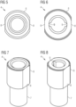
- FIG 5 a plain view of the housing 4 for a sensor 1 according to the first embodiment of the present invention is shown. It shows the first portion 6 of the housing 4 which forms a round opening in the middle.
- the outer shape and contour of the first portion 6 is not radial symmetrical.
- the contour of the housing 4 has two flattened segments 8 which are opposite to each other. In this way the sensor 1 can be securely picked at the flattened segment 8, as the flattened segment 8 provide means for a stable grip.
- the sensor 1 also can easily be mounted and installed in a device by a pick-and-place machine.
- the direction the sensor element 2 is facing in the housing 4 as well as the direction of the housing 4 in a device is determined and fixed. As a consequence the position and the direction of the sensor 1 is exactly the same in a device. Sensor elements 2 often are very dependent on the angle they face an event they are supposed to measure. As an example, a planar temperature sensor element 2 that faces a heat source with its large surface will absorb more thermal energy than a NTC sensor that is orientated perpendicular to the heat source. By determining the direction of the sensor element 2 in the housing 4 and the direction of the housing 4 in a device by its outer shape and contour it is ensured that the sensor element 2 and thereby the sensor 1 itself works and measures reliable and reproducible values.
- FIG 6 a plain view of a housing 4 for a sensor 1 according to the second embodiment, also shown in figures 2 and 4 , is presented.
- the main difference in contrast to the first embodiment shown in figure 5 are two grooves 9 that are arranged in the inner surface of the housing 4.
- the grooves 9 are located central relatively to the flattened segments 8 that are part of the outer contour of the housing 4.
- the orientation of the sensor element 2 in the housing 4 is predetermined relatively to the flattened segments 8. In this way it is ensured that the sensor 1 measures reproducible in a given environment where to orientation and location of the housing is specified.
- FIG 7 shows a perspective view of the housing 4 for a sensor 1 shown in figures 3 and 5 .
- the housing 4 has two portions, is not radial symmetrical and has two flattened segments 8 on the first portion 6. It is made out of alumina oxide, which is a metal oxide, with 96% alumina and 4% oxygen. Metal oxides offer a high stability and relatively high thermal conductivity. Moreover, metal oxides are electrical insulators. Therefore, the sensor 1 with a housing 4 made of a metal oxide is convenient for high-voltage applications. As a high voltage applied to the electrical can easily cause short circuits, especially between the protruding electrical leads 3 and the housing 4, a housing 4 made of an electrical insulator can be beneficial.
- the sensor 1 employing the housing 4 shown in figure 7 which is made out of a metal oxide, can be operated with a voltage of up to 10 kV.
- a similar housing as in figure 7 is shown in a second embodiment shown in figure 8 . Both embodiments differ in the two grooves 9 that are disposed in the inners surface of the housing 4. The electrical leads 3 can latch into this grooves 9 and fix thereby the orientation of the sensor element 2 in the housing 4.
- the housing 4 can be made out of metal.
- Metal is robust and provides a great thermal conductivity. In addition, it is resistant to harmful external environmental influences.
- a metal housing material can be suitable as such a sensor 1 is more sensitive.
Landscapes
- Physics & Mathematics (AREA)
- General Physics & Mathematics (AREA)
- Engineering & Computer Science (AREA)
- Microelectronics & Electronic Packaging (AREA)
- Nonlinear Science (AREA)
- Electromagnetism (AREA)
- Testing Or Calibration Of Command Recording Devices (AREA)
- Measuring Temperature Or Quantity Of Heat (AREA)
- Thermistors And Varistors (AREA)
- Measuring Instrument Details And Bridges, And Automatic Balancing Devices (AREA)
Claims (13)
- Sensor (1), umfassend:- ein Sensorelement (2);- elektrische Leitungen (3);
wobei das Sensorelement (2) mit den elektrischen Leitungen (3) verbunden ist;- ein Gehäuse (4);
wobei das Gehäuse (4) eine Öffnung aufweist und das Sensorelement (2) in dem Gehäuse (4) so angeordnet ist, dass die elektrischen Leitungen (3) aus der Öffnung herausragen; und wobei die elektrischen Leitungen (3) in einem Abschnitt, der sich innerhalb des Gehäuses (4) befindet, Knicke (10) aufweisen;- Epoxidharz (5);wobei das Gehäuse (4) mit dem Epoxidharz (5) gefüllt ist und das Epoxidharz (5) das Sensorelement (2) und die elektrischen Leitungen (3) in dem Gehäuse (4) fixiert, dadurch gekennzeichnet, dassdas Gehäuse (4) an einer Innenfläche des Gehäuses (4) zwei Nuten (9) aufweist, die sich von der Öffnung aus entlang einer Längsachse in das Gehäuse (4) erstrecken,
unddass die elektrischen Leitungen (3) in den Nuten (9) angeordnet sind und durch die Knicke (10) der elektrischen Leitungen (3) eine Querkraft erzeugt wird, die ein Einrasten der elektrischen Leitungen (3) in den Nuten (9) unterstützt. - Sensor (1) nach dem vorhergehenden Anspruch,
wobei es sich bei dem Sensorelement (2) um ein NTC-Sensorelement (2) handelt. - Sensor (1) nach einem der vorhergehenden Ansprüche, wobei das Gehäuse (4) zwei Abschnitte aufweist, einen ersten Abschnitt (6), der die Öffnung umfasst, und einen zweiten Abschnitt (7), der der Seite der Öffnung gegenüberliegt, und
wobei der zweite Abschnitt (7) einen kleineren Durchmesser als der erste Abschnitt (6) aufweist und das Sensorelement (2) in dem zweiten Abschnitt (7) des Gehäuses (4) angeordnet ist. - Sensor (1) nach einem der vorhergehenden Ansprüche, wobei die Außenform des Gehäuses (4) nicht radialsymmetrisch ist.
- Sensor (1) nach einem der vorhergehenden Ansprüche, wobei die Kontur des Gehäuses (4) mindestens zwei abgeflachte Segmente (8) aufweist, die einander gegenüberliegen.
- Sensor (1) nach einem der vorhergehenden Ansprüche, wobei eine Wanddicke des Gehäuses (4) weniger als 2 mm beträgt.
- Sensor (1) nach einem der vorhergehenden Ansprüche, wobei das Gehäuse (4) aus Metall hergestellt ist.
- Sensor (1) nach einem der Ansprüche 1 bis 6, wobei das Gehäuse (4) aus einem Metalloxid hergestellt ist.
- Sensor (1) nach einem der vorhergehenden Ansprüche, wobei es sich bei dem Epoxidharz (5) um ein Zweikomponenten-Epoxidharz (5) handelt.
- Sensor (1) nach einem der vorhergehenden Ansprüche, wobei es sich bei einem das Sensorelement (2) einkapselnden Material um dasselbe Material handelt, das die Innenseite des Gehäuses (4) berührt und das Sensorelement (2) am Gehäuse (4) fixiert.
- Sensor (1) nach einem der vorhergehenden Ansprüche, wobei der Sensor (1) geeignet ist, von einer Bestückungsmaschine montiert zu werden.
- Anordnung, umfassend:- einen Sensor (1) nach einem der vorhergehenden Ansprüche,- eine Leiterplatte (PCB),wobei der Sensor auf der Leiterplatte angeordnet und mit der Leiterplatte elektrisch verbunden ist.
- Intelligenter Leistungsmesser, der einen Sensor (1) nach einem der Ansprüche 1 bis 11 oder eine Anordnung nach Anspruch 12 umfasst.
Applications Claiming Priority (3)
| Application Number | Priority Date | Filing Date | Title |
|---|---|---|---|
| DE202019104670.8U DE202019104670U1 (de) | 2019-08-26 | 2019-08-26 | Sensor |
| DE102019129521.1A DE102019129521A1 (de) | 2019-08-26 | 2019-10-31 | Sensor |
| PCT/EP2020/073409 WO2021037689A1 (en) | 2019-08-26 | 2020-08-20 | Sensor |
Publications (2)
| Publication Number | Publication Date |
|---|---|
| EP4022271A1 EP4022271A1 (de) | 2022-07-06 |
| EP4022271B1 true EP4022271B1 (de) | 2024-09-25 |
Family
ID=69226748
Family Applications (1)
| Application Number | Title | Priority Date | Filing Date |
|---|---|---|---|
| EP20761772.1A Active EP4022271B1 (de) | 2019-08-26 | 2020-08-20 | Sensor |
Country Status (6)
| Country | Link |
|---|---|
| US (1) | US12313472B2 (de) |
| EP (1) | EP4022271B1 (de) |
| JP (1) | JP7326592B2 (de) |
| CN (2) | CN112432658B (de) |
| DE (2) | DE202019104670U1 (de) |
| WO (1) | WO2021037689A1 (de) |
Families Citing this family (4)
| Publication number | Priority date | Publication date | Assignee | Title |
|---|---|---|---|---|
| DE102020116018A1 (de) | 2020-06-17 | 2021-12-23 | Tdk Electronics Ag | Sensor |
| DE102020133985A1 (de) | 2020-12-17 | 2022-06-23 | Tdk Electronics Ag | Sensoranordnung und Verfahren zur Herstellung einer Sensoranordnung |
| DE102024114415B4 (de) * | 2024-05-23 | 2026-01-29 | Ust Umweltsensortechnik Gmbh | Sensor |
| CN119223370B (zh) * | 2024-12-03 | 2025-03-07 | 宁波九荣环保科技有限公司 | 一种压力-温度梯度耦合传感器及其应用 |
Family Cites Families (28)
| Publication number | Priority date | Publication date | Assignee | Title |
|---|---|---|---|---|
| JPH0430781Y2 (de) * | 1986-10-09 | 1992-07-24 | ||
| JPH0385714A (ja) | 1989-08-30 | 1991-04-10 | Nippon Chemicon Corp | 電解コンデンサ |
| JP3319990B2 (ja) | 1997-08-29 | 2002-09-03 | 三菱電機株式会社 | 圧力センサ装置 |
| JP3870917B2 (ja) | 2003-03-19 | 2007-01-24 | 株式会社デンソー | 温度センサ一体型圧力センサ装置及びその温度センサ固定方法 |
| JP4041018B2 (ja) | 2003-06-25 | 2008-01-30 | Tdk株式会社 | 温度センサ |
| JP4620400B2 (ja) * | 2004-07-16 | 2011-01-26 | 日本特殊陶業株式会社 | 温度センサ、温度センサの製造方法 |
| JP5262448B2 (ja) * | 2008-08-28 | 2013-08-14 | Tdk株式会社 | サーミスタ |
| JP5429476B2 (ja) * | 2008-11-20 | 2014-02-26 | Tdk株式会社 | 温度センサ |
| JP2011027576A (ja) * | 2009-07-27 | 2011-02-10 | Daikin Industries Ltd | 樹脂封止型センサ |
| JP5523982B2 (ja) * | 2010-08-16 | 2014-06-18 | 株式会社芝浦電子 | 温度センサ |
| US8635036B2 (en) | 2011-01-04 | 2014-01-21 | General Electric Company | Systems, methods, and apparatus for providing energy management utilizing a power meter |
| DE102011008179B4 (de) * | 2011-01-10 | 2012-11-29 | Paul Rüster & Co. GmbH | Temperaturfühler |
| US8830083B2 (en) * | 2011-05-25 | 2014-09-09 | General Electric Company | Utility meter with temperature based actuation of a remote disconnect switch |
| CN103620779B (zh) | 2011-07-19 | 2016-12-28 | 赫普塔冈微光有限公司 | 光电模块及其制造方法 |
| FR2988172B1 (fr) | 2012-03-19 | 2014-12-26 | Sc2N Sa | Capteur de temperature |
| US20130248777A1 (en) * | 2012-03-26 | 2013-09-26 | Heraeus Precious Metals North America Conshohocken Llc | Low silver content paste composition and method of making a conductive film therefrom |
| DE102012110858A1 (de) | 2012-11-12 | 2014-05-15 | Epcos Ag | Temperatursensorsystem und Verfahren zur Herstellung eines Temperatursensorsystems |
| DE102012110845A1 (de) * | 2012-11-12 | 2014-05-15 | Epcos Ag | Temperaturfühler und Verfahren zur Herstellung eines Temperaturfühlers |
| CN203551136U (zh) * | 2013-10-18 | 2014-04-16 | 孝感华工高理电子有限公司 | 一种防裂胶结构压缩机温度传感器 |
| US10317289B2 (en) * | 2014-09-10 | 2019-06-11 | Rockwell Automation Technologies, Inc. | Thermal well for transformer and methods |
| JP6228532B2 (ja) * | 2014-12-19 | 2017-11-08 | Tdk株式会社 | サーミスタ |
| CN205262633U (zh) * | 2015-10-06 | 2016-05-25 | 佛山市顺德区万诺传感技术有限公司 | 一种防漏电ntc温度传感器 |
| EP3431944B1 (de) * | 2017-01-16 | 2020-04-01 | Shibaura Electronics Co., Ltd. | Temperatursensor |
| JP6631583B2 (ja) | 2017-04-19 | 2020-01-15 | Tdk株式会社 | 温度センサ装置 |
| JP6966248B2 (ja) | 2017-07-18 | 2021-11-10 | アルプスアルパイン株式会社 | センサーユニット |
| CN107860480A (zh) * | 2017-12-26 | 2018-03-30 | 福州普贝斯智能科技有限公司 | 水质分析传感器中的温度测量装置 |
| CN109073480B (zh) * | 2018-02-13 | 2022-07-05 | 株式会社芝浦电子 | 温度传感器、传感器元件以及温度传感器的制造方法 |
| WO2021095244A1 (ja) * | 2019-11-15 | 2021-05-20 | 株式会社芝浦電子 | 温度センサ、温度センサ素子および温度センサの製造方法 |
-
2019
- 2019-08-26 DE DE202019104670.8U patent/DE202019104670U1/de not_active Expired - Lifetime
- 2019-10-31 CN CN201911054498.9A patent/CN112432658B/zh active Active
- 2019-10-31 CN CN201921857733.1U patent/CN211740245U8/zh active Active
- 2019-10-31 DE DE102019129521.1A patent/DE102019129521A1/de not_active Withdrawn
-
2020
- 2020-08-20 WO PCT/EP2020/073409 patent/WO2021037689A1/en not_active Ceased
- 2020-08-20 JP JP2022513344A patent/JP7326592B2/ja active Active
- 2020-08-20 EP EP20761772.1A patent/EP4022271B1/de active Active
- 2020-08-20 US US17/634,603 patent/US12313472B2/en active Active
Also Published As
| Publication number | Publication date |
|---|---|
| DE102019129521A1 (de) | 2021-03-04 |
| DE202019104670U1 (de) | 2019-12-10 |
| US20220326088A1 (en) | 2022-10-13 |
| WO2021037689A1 (en) | 2021-03-04 |
| CN112432658B (zh) | 2023-01-24 |
| JP2022546066A (ja) | 2022-11-02 |
| CN112432658A (zh) | 2021-03-02 |
| CN211740245U (zh) | 2020-10-23 |
| CN211740245U8 (zh) | 2020-11-20 |
| JP7326592B2 (ja) | 2023-08-15 |
| EP4022271A1 (de) | 2022-07-06 |
| US12313472B2 (en) | 2025-05-27 |
Similar Documents
| Publication | Publication Date | Title |
|---|---|---|
| EP4022271B1 (de) | Sensor | |
| US11422050B2 (en) | Temperature-pressure integrated sensor with improved assembly and processing | |
| CN109041578B (zh) | 温度传感器 | |
| US20090039880A1 (en) | Electric current detector having detector element holder coupled to magnetic core casing | |
| JP7175251B2 (ja) | 温度センサ及びそれを備える配電部品、配電部品を備えるモータ | |
| JP2013174555A (ja) | 電池状態検出装置 | |
| US20190066897A1 (en) | Coil part | |
| US11796574B2 (en) | Integration of current sensor with busbar | |
| EP3217153B1 (de) | Thermischer luftmassenmesser | |
| US11509013B2 (en) | Storage battery module | |
| KR101843249B1 (ko) | 전자 소자 모듈 및 전자 소자 모듈의 차폐 측정 방법 | |
| US20230366743A1 (en) | Measuring device | |
| EP4168746B1 (de) | Sensor mit gehäuse und silikonharzfüllung | |
| JP2020153696A (ja) | 温度センサ | |
| JP2017139425A (ja) | リアクトル | |
| JP2015190930A (ja) | 電流センサ | |
| CN209841227U (zh) | 三支型全铠装快速铂热电阻 | |
| Kim et al. | High withstand voltage pressure sensors based on silicon strain gauges-on-a-glass substrate | |
| KR102002324B1 (ko) | 방폭형 로드셀 장치 | |
| US20160109524A1 (en) | Arrangement for Determining Characteristic Variables of an Electrochemical Energy Store | |
| JP2021156730A (ja) | 温度検出装置及び配線部品 | |
| JP2026006612A (ja) | 温度検出体固定用溝付き絶縁キャップ、回転電機の温度検出体固定構造、温度検出体固定済み回転電機、回転電機の温度検出体固定方法、および回転電機製造装置 | |
| JPH04298002A (ja) | 樹脂封止形サーミスタ | |
| KR20070100474A (ko) | 자기장 차폐 기능을 가지는 온도센서 | |
| CZ281656B6 (cs) | Teplotní čidlo pro měření povrchové i objemové teploty |
Legal Events
| Date | Code | Title | Description |
|---|---|---|---|
| STAA | Information on the status of an ep patent application or granted ep patent |
Free format text: STATUS: UNKNOWN |
|
| STAA | Information on the status of an ep patent application or granted ep patent |
Free format text: STATUS: THE INTERNATIONAL PUBLICATION HAS BEEN MADE |
|
| PUAI | Public reference made under article 153(3) epc to a published international application that has entered the european phase |
Free format text: ORIGINAL CODE: 0009012 |
|
| STAA | Information on the status of an ep patent application or granted ep patent |
Free format text: STATUS: REQUEST FOR EXAMINATION WAS MADE |
|
| 17P | Request for examination filed |
Effective date: 20220203 |
|
| AK | Designated contracting states |
Kind code of ref document: A1 Designated state(s): AL AT BE BG CH CY CZ DE DK EE ES FI FR GB GR HR HU IE IS IT LI LT LU LV MC MK MT NL NO PL PT RO RS SE SI SK SM TR |
|
| DAV | Request for validation of the european patent (deleted) | ||
| DAX | Request for extension of the european patent (deleted) | ||
| GRAP | Despatch of communication of intention to grant a patent |
Free format text: ORIGINAL CODE: EPIDOSNIGR1 |
|
| STAA | Information on the status of an ep patent application or granted ep patent |
Free format text: STATUS: GRANT OF PATENT IS INTENDED |
|
| RIC1 | Information provided on ipc code assigned before grant |
Ipc: G01D 11/24 20060101ALI20240305BHEP Ipc: H01C 7/04 20060101ALI20240305BHEP Ipc: G01K 7/22 20060101ALI20240305BHEP Ipc: G01K 1/08 20210101AFI20240305BHEP |
|
| INTG | Intention to grant announced |
Effective date: 20240321 |
|
| P01 | Opt-out of the competence of the unified patent court (upc) registered |
Effective date: 20240525 |
|
| GRAS | Grant fee paid |
Free format text: ORIGINAL CODE: EPIDOSNIGR3 |
|
| GRAA | (expected) grant |
Free format text: ORIGINAL CODE: 0009210 |
|
| STAA | Information on the status of an ep patent application or granted ep patent |
Free format text: STATUS: THE PATENT HAS BEEN GRANTED |
|
| AK | Designated contracting states |
Kind code of ref document: B1 Designated state(s): AL AT BE BG CH CY CZ DE DK EE ES FI FR GB GR HR HU IE IS IT LI LT LU LV MC MK MT NL NO PL PT RO RS SE SI SK SM TR |
|
| REG | Reference to a national code |
Ref country code: GB Ref legal event code: FG4D |
|
| REG | Reference to a national code |
Ref country code: CH Ref legal event code: EP |
|
| REG | Reference to a national code |
Ref country code: DE Ref legal event code: R096 Ref document number: 602020038340 Country of ref document: DE |
|
| REG | Reference to a national code |
Ref country code: IE Ref legal event code: FG4D |
|
| REG | Reference to a national code |
Ref country code: LT Ref legal event code: MG9D |
|
| PG25 | Lapsed in a contracting state [announced via postgrant information from national office to epo] |
Ref country code: NO Free format text: LAPSE BECAUSE OF FAILURE TO SUBMIT A TRANSLATION OF THE DESCRIPTION OR TO PAY THE FEE WITHIN THE PRESCRIBED TIME-LIMIT Effective date: 20241225 |
|
| PG25 | Lapsed in a contracting state [announced via postgrant information from national office to epo] |
Ref country code: GR Free format text: LAPSE BECAUSE OF FAILURE TO SUBMIT A TRANSLATION OF THE DESCRIPTION OR TO PAY THE FEE WITHIN THE PRESCRIBED TIME-LIMIT Effective date: 20241226 Ref country code: FI Free format text: LAPSE BECAUSE OF FAILURE TO SUBMIT A TRANSLATION OF THE DESCRIPTION OR TO PAY THE FEE WITHIN THE PRESCRIBED TIME-LIMIT Effective date: 20240925 |
|
| PG25 | Lapsed in a contracting state [announced via postgrant information from national office to epo] |
Ref country code: BG Free format text: LAPSE BECAUSE OF FAILURE TO SUBMIT A TRANSLATION OF THE DESCRIPTION OR TO PAY THE FEE WITHIN THE PRESCRIBED TIME-LIMIT Effective date: 20240925 |
|
| PG25 | Lapsed in a contracting state [announced via postgrant information from national office to epo] |
Ref country code: LV Free format text: LAPSE BECAUSE OF FAILURE TO SUBMIT A TRANSLATION OF THE DESCRIPTION OR TO PAY THE FEE WITHIN THE PRESCRIBED TIME-LIMIT Effective date: 20240925 |
|
| PG25 | Lapsed in a contracting state [announced via postgrant information from national office to epo] |
Ref country code: RS Free format text: LAPSE BECAUSE OF FAILURE TO SUBMIT A TRANSLATION OF THE DESCRIPTION OR TO PAY THE FEE WITHIN THE PRESCRIBED TIME-LIMIT Effective date: 20241225 |
|
| REG | Reference to a national code |
Ref country code: NL Ref legal event code: MP Effective date: 20240925 |
|
| PG25 | Lapsed in a contracting state [announced via postgrant information from national office to epo] |
Ref country code: RS Free format text: LAPSE BECAUSE OF FAILURE TO SUBMIT A TRANSLATION OF THE DESCRIPTION OR TO PAY THE FEE WITHIN THE PRESCRIBED TIME-LIMIT Effective date: 20241225 Ref country code: NO Free format text: LAPSE BECAUSE OF FAILURE TO SUBMIT A TRANSLATION OF THE DESCRIPTION OR TO PAY THE FEE WITHIN THE PRESCRIBED TIME-LIMIT Effective date: 20241225 Ref country code: LV Free format text: LAPSE BECAUSE OF FAILURE TO SUBMIT A TRANSLATION OF THE DESCRIPTION OR TO PAY THE FEE WITHIN THE PRESCRIBED TIME-LIMIT Effective date: 20240925 Ref country code: GR Free format text: LAPSE BECAUSE OF FAILURE TO SUBMIT A TRANSLATION OF THE DESCRIPTION OR TO PAY THE FEE WITHIN THE PRESCRIBED TIME-LIMIT Effective date: 20241226 Ref country code: FI Free format text: LAPSE BECAUSE OF FAILURE TO SUBMIT A TRANSLATION OF THE DESCRIPTION OR TO PAY THE FEE WITHIN THE PRESCRIBED TIME-LIMIT Effective date: 20240925 Ref country code: BG Free format text: LAPSE BECAUSE OF FAILURE TO SUBMIT A TRANSLATION OF THE DESCRIPTION OR TO PAY THE FEE WITHIN THE PRESCRIBED TIME-LIMIT Effective date: 20240925 |
|
| REG | Reference to a national code |
Ref country code: AT Ref legal event code: MK05 Ref document number: 1726985 Country of ref document: AT Kind code of ref document: T Effective date: 20240925 |
|
| PG25 | Lapsed in a contracting state [announced via postgrant information from national office to epo] |
Ref country code: NL Free format text: LAPSE BECAUSE OF FAILURE TO SUBMIT A TRANSLATION OF THE DESCRIPTION OR TO PAY THE FEE WITHIN THE PRESCRIBED TIME-LIMIT Effective date: 20240925 |
|
| PG25 | Lapsed in a contracting state [announced via postgrant information from national office to epo] |
Ref country code: PT Free format text: LAPSE BECAUSE OF FAILURE TO SUBMIT A TRANSLATION OF THE DESCRIPTION OR TO PAY THE FEE WITHIN THE PRESCRIBED TIME-LIMIT Effective date: 20250127 Ref country code: IS Free format text: LAPSE BECAUSE OF FAILURE TO SUBMIT A TRANSLATION OF THE DESCRIPTION OR TO PAY THE FEE WITHIN THE PRESCRIBED TIME-LIMIT Effective date: 20250125 |
|
| PG25 | Lapsed in a contracting state [announced via postgrant information from national office to epo] |
Ref country code: RO Free format text: LAPSE BECAUSE OF FAILURE TO SUBMIT A TRANSLATION OF THE DESCRIPTION OR TO PAY THE FEE WITHIN THE PRESCRIBED TIME-LIMIT Effective date: 20240925 Ref country code: SM Free format text: LAPSE BECAUSE OF FAILURE TO SUBMIT A TRANSLATION OF THE DESCRIPTION OR TO PAY THE FEE WITHIN THE PRESCRIBED TIME-LIMIT Effective date: 20240925 |
|
| PG25 | Lapsed in a contracting state [announced via postgrant information from national office to epo] |
Ref country code: ES Free format text: LAPSE BECAUSE OF FAILURE TO SUBMIT A TRANSLATION OF THE DESCRIPTION OR TO PAY THE FEE WITHIN THE PRESCRIBED TIME-LIMIT Effective date: 20240925 |
|
| PG25 | Lapsed in a contracting state [announced via postgrant information from national office to epo] |
Ref country code: EE Free format text: LAPSE BECAUSE OF FAILURE TO SUBMIT A TRANSLATION OF THE DESCRIPTION OR TO PAY THE FEE WITHIN THE PRESCRIBED TIME-LIMIT Effective date: 20240925 Ref country code: AT Free format text: LAPSE BECAUSE OF FAILURE TO SUBMIT A TRANSLATION OF THE DESCRIPTION OR TO PAY THE FEE WITHIN THE PRESCRIBED TIME-LIMIT Effective date: 20240925 |
|
| PG25 | Lapsed in a contracting state [announced via postgrant information from national office to epo] |
Ref country code: PL Free format text: LAPSE BECAUSE OF FAILURE TO SUBMIT A TRANSLATION OF THE DESCRIPTION OR TO PAY THE FEE WITHIN THE PRESCRIBED TIME-LIMIT Effective date: 20240925 Ref country code: CZ Free format text: LAPSE BECAUSE OF FAILURE TO SUBMIT A TRANSLATION OF THE DESCRIPTION OR TO PAY THE FEE WITHIN THE PRESCRIBED TIME-LIMIT Effective date: 20240925 |
|
| PG25 | Lapsed in a contracting state [announced via postgrant information from national office to epo] |
Ref country code: SK Free format text: LAPSE BECAUSE OF FAILURE TO SUBMIT A TRANSLATION OF THE DESCRIPTION OR TO PAY THE FEE WITHIN THE PRESCRIBED TIME-LIMIT Effective date: 20240925 Ref country code: IT Free format text: LAPSE BECAUSE OF FAILURE TO SUBMIT A TRANSLATION OF THE DESCRIPTION OR TO PAY THE FEE WITHIN THE PRESCRIBED TIME-LIMIT Effective date: 20240925 |
|
| REG | Reference to a national code |
Ref country code: DE Ref legal event code: R097 Ref document number: 602020038340 Country of ref document: DE |
|
| PG25 | Lapsed in a contracting state [announced via postgrant information from national office to epo] |
Ref country code: DK Free format text: LAPSE BECAUSE OF FAILURE TO SUBMIT A TRANSLATION OF THE DESCRIPTION OR TO PAY THE FEE WITHIN THE PRESCRIBED TIME-LIMIT Effective date: 20240925 |
|
| PLBE | No opposition filed within time limit |
Free format text: ORIGINAL CODE: 0009261 |
|
| STAA | Information on the status of an ep patent application or granted ep patent |
Free format text: STATUS: NO OPPOSITION FILED WITHIN TIME LIMIT |
|
| 26N | No opposition filed |
Effective date: 20250626 |
|
| PG25 | Lapsed in a contracting state [announced via postgrant information from national office to epo] |
Ref country code: SE Free format text: LAPSE BECAUSE OF FAILURE TO SUBMIT A TRANSLATION OF THE DESCRIPTION OR TO PAY THE FEE WITHIN THE PRESCRIBED TIME-LIMIT Effective date: 20240925 |
|
| PGFP | Annual fee paid to national office [announced via postgrant information from national office to epo] |
Ref country code: DE Payment date: 20250825 Year of fee payment: 6 |
|
| PG25 | Lapsed in a contracting state [announced via postgrant information from national office to epo] |
Ref country code: HR Free format text: LAPSE BECAUSE OF FAILURE TO SUBMIT A TRANSLATION OF THE DESCRIPTION OR TO PAY THE FEE WITHIN THE PRESCRIBED TIME-LIMIT Effective date: 20240925 |
|
| REG | Reference to a national code |
Ref country code: CH Ref legal event code: H13 Free format text: ST27 STATUS EVENT CODE: U-0-0-H10-H13 (AS PROVIDED BY THE NATIONAL OFFICE) Effective date: 20260324 |
|
| PG25 | Lapsed in a contracting state [announced via postgrant information from national office to epo] |
Ref country code: MC Free format text: LAPSE BECAUSE OF FAILURE TO SUBMIT A TRANSLATION OF THE DESCRIPTION OR TO PAY THE FEE WITHIN THE PRESCRIBED TIME-LIMIT Effective date: 20240925 |
|
| PG25 | Lapsed in a contracting state [announced via postgrant information from national office to epo] |
Ref country code: LU Free format text: LAPSE BECAUSE OF NON-PAYMENT OF DUE FEES Effective date: 20250820 |
|
| PG25 | Lapsed in a contracting state [announced via postgrant information from national office to epo] |
Ref country code: CH Free format text: LAPSE BECAUSE OF NON-PAYMENT OF DUE FEES Effective date: 20250831 |