EP4021370B1 - Dichtungsstruktur für den fliessweg, beutelförmiger behälter und verfahren zur herstellung desselben - Google Patents
Dichtungsstruktur für den fliessweg, beutelförmiger behälter und verfahren zur herstellung desselben Download PDFInfo
- Publication number
- EP4021370B1 EP4021370B1 EP20781639.8A EP20781639A EP4021370B1 EP 4021370 B1 EP4021370 B1 EP 4021370B1 EP 20781639 A EP20781639 A EP 20781639A EP 4021370 B1 EP4021370 B1 EP 4021370B1
- Authority
- EP
- European Patent Office
- Prior art keywords
- flow path
- resin sheets
- bag
- fusion bonding
- widened
- Prior art date
- Legal status (The legal status is an assumption and is not a legal conclusion. Google has not performed a legal analysis and makes no representation as to the accuracy of the status listed.)
- Active
Links
Images




Classifications
-
- A—HUMAN NECESSITIES
- A61—MEDICAL OR VETERINARY SCIENCE; HYGIENE
- A61J—CONTAINERS SPECIALLY ADAPTED FOR MEDICAL OR PHARMACEUTICAL PURPOSES; DEVICES OR METHODS SPECIALLY ADAPTED FOR BRINGING PHARMACEUTICAL PRODUCTS INTO PARTICULAR PHYSICAL OR ADMINISTERING FORMS; DEVICES FOR ADMINISTERING FOOD OR MEDICINES ORALLY; BABY COMFORTERS; DEVICES FOR RECEIVING SPITTLE
- A61J1/00—Containers specially adapted for medical or pharmaceutical purposes
- A61J1/05—Containers specially adapted for medical or pharmaceutical purposes for collecting, storing or administering blood, plasma or medical fluids ; Infusion or perfusion containers
- A61J1/10—Bag-type containers
-
- A—HUMAN NECESSITIES
- A61—MEDICAL OR VETERINARY SCIENCE; HYGIENE
- A61J—CONTAINERS SPECIALLY ADAPTED FOR MEDICAL OR PHARMACEUTICAL PURPOSES; DEVICES OR METHODS SPECIALLY ADAPTED FOR BRINGING PHARMACEUTICAL PRODUCTS INTO PARTICULAR PHYSICAL OR ADMINISTERING FORMS; DEVICES FOR ADMINISTERING FOOD OR MEDICINES ORALLY; BABY COMFORTERS; DEVICES FOR RECEIVING SPITTLE
- A61J1/00—Containers specially adapted for medical or pharmaceutical purposes
- A61J1/05—Containers specially adapted for medical or pharmaceutical purposes for collecting, storing or administering blood, plasma or medical fluids ; Infusion or perfusion containers
- A61J1/10—Bag-type containers
- A61J1/12—Bag-type containers with means for holding samples of contents
-
- A—HUMAN NECESSITIES
- A61—MEDICAL OR VETERINARY SCIENCE; HYGIENE
- A61J—CONTAINERS SPECIALLY ADAPTED FOR MEDICAL OR PHARMACEUTICAL PURPOSES; DEVICES OR METHODS SPECIALLY ADAPTED FOR BRINGING PHARMACEUTICAL PRODUCTS INTO PARTICULAR PHYSICAL OR ADMINISTERING FORMS; DEVICES FOR ADMINISTERING FOOD OR MEDICINES ORALLY; BABY COMFORTERS; DEVICES FOR RECEIVING SPITTLE
- A61J1/00—Containers specially adapted for medical or pharmaceutical purposes
- A61J1/14—Details; Accessories therefor
- A61J1/1412—Containers with closing means, e.g. caps
-
- A—HUMAN NECESSITIES
- A61—MEDICAL OR VETERINARY SCIENCE; HYGIENE
- A61J—CONTAINERS SPECIALLY ADAPTED FOR MEDICAL OR PHARMACEUTICAL PURPOSES; DEVICES OR METHODS SPECIALLY ADAPTED FOR BRINGING PHARMACEUTICAL PRODUCTS INTO PARTICULAR PHYSICAL OR ADMINISTERING FORMS; DEVICES FOR ADMINISTERING FOOD OR MEDICINES ORALLY; BABY COMFORTERS; DEVICES FOR RECEIVING SPITTLE
- A61J1/00—Containers specially adapted for medical or pharmaceutical purposes
- A61J1/14—Details; Accessories therefor
- A61J1/20—Arrangements for transferring or mixing fluids, e.g. from vial to syringe
- A61J1/2003—Accessories used in combination with means for transfer or mixing of fluids, e.g. for activating fluid flow, separating fluids, filtering fluid or venting
- A61J1/202—Separating means
- A61J1/2024—Separating means having peelable seals
-
- B—PERFORMING OPERATIONS; TRANSPORTING
- B29—WORKING OF PLASTICS; WORKING OF SUBSTANCES IN A PLASTIC STATE IN GENERAL
- B29C—SHAPING OR JOINING OF PLASTICS; SHAPING OF MATERIAL IN A PLASTIC STATE, NOT OTHERWISE PROVIDED FOR; AFTER-TREATMENT OF THE SHAPED PRODUCTS, e.g. REPAIRING
- B29C65/00—Joining or sealing of preformed parts, e.g. welding of plastics materials; Apparatus therefor
- B29C65/02—Joining or sealing of preformed parts, e.g. welding of plastics materials; Apparatus therefor by heating, with or without pressure
-
- B—PERFORMING OPERATIONS; TRANSPORTING
- B29—WORKING OF PLASTICS; WORKING OF SUBSTANCES IN A PLASTIC STATE IN GENERAL
- B29C—SHAPING OR JOINING OF PLASTICS; SHAPING OF MATERIAL IN A PLASTIC STATE, NOT OTHERWISE PROVIDED FOR; AFTER-TREATMENT OF THE SHAPED PRODUCTS, e.g. REPAIRING
- B29C65/00—Joining or sealing of preformed parts, e.g. welding of plastics materials; Apparatus therefor
- B29C65/02—Joining or sealing of preformed parts, e.g. welding of plastics materials; Apparatus therefor by heating, with or without pressure
- B29C65/04—Dielectric heating, e.g. high-frequency welding, i.e. radio frequency welding of plastic materials having dielectric properties, e.g. PVC
-
- B—PERFORMING OPERATIONS; TRANSPORTING
- B29—WORKING OF PLASTICS; WORKING OF SUBSTANCES IN A PLASTIC STATE IN GENERAL
- B29C—SHAPING OR JOINING OF PLASTICS; SHAPING OF MATERIAL IN A PLASTIC STATE, NOT OTHERWISE PROVIDED FOR; AFTER-TREATMENT OF THE SHAPED PRODUCTS, e.g. REPAIRING
- B29C65/00—Joining or sealing of preformed parts, e.g. welding of plastics materials; Apparatus therefor
- B29C65/76—Making non-permanent or releasable joints
-
- B—PERFORMING OPERATIONS; TRANSPORTING
- B29—WORKING OF PLASTICS; WORKING OF SUBSTANCES IN A PLASTIC STATE IN GENERAL
- B29C—SHAPING OR JOINING OF PLASTICS; SHAPING OF MATERIAL IN A PLASTIC STATE, NOT OTHERWISE PROVIDED FOR; AFTER-TREATMENT OF THE SHAPED PRODUCTS, e.g. REPAIRING
- B29C65/00—Joining or sealing of preformed parts, e.g. welding of plastics materials; Apparatus therefor
- B29C65/82—Testing the joint
- B29C65/8207—Testing the joint by mechanical methods
- B29C65/8246—Pressure tests, e.g. hydrostatic pressure tests
-
- B—PERFORMING OPERATIONS; TRANSPORTING
- B29—WORKING OF PLASTICS; WORKING OF SUBSTANCES IN A PLASTIC STATE IN GENERAL
- B29C—SHAPING OR JOINING OF PLASTICS; SHAPING OF MATERIAL IN A PLASTIC STATE, NOT OTHERWISE PROVIDED FOR; AFTER-TREATMENT OF THE SHAPED PRODUCTS, e.g. REPAIRING
- B29C66/00—General aspects of processes or apparatus for joining preformed parts
- B29C66/01—General aspects dealing with the joint area or with the area to be joined
- B29C66/05—Particular design of joint configurations
- B29C66/10—Particular design of joint configurations particular design of the joint cross-sections
- B29C66/11—Joint cross-sections comprising a single joint-segment, i.e. one of the parts to be joined comprising a single joint-segment in the joint cross-section
- B29C66/112—Single lapped joints
- B29C66/1122—Single lap to lap joints, i.e. overlap joints
-
- B—PERFORMING OPERATIONS; TRANSPORTING
- B29—WORKING OF PLASTICS; WORKING OF SUBSTANCES IN A PLASTIC STATE IN GENERAL
- B29C—SHAPING OR JOINING OF PLASTICS; SHAPING OF MATERIAL IN A PLASTIC STATE, NOT OTHERWISE PROVIDED FOR; AFTER-TREATMENT OF THE SHAPED PRODUCTS, e.g. REPAIRING
- B29C66/00—General aspects of processes or apparatus for joining preformed parts
- B29C66/01—General aspects dealing with the joint area or with the area to be joined
- B29C66/05—Particular design of joint configurations
- B29C66/20—Particular design of joint configurations particular design of the joint lines, e.g. of the weld lines
- B29C66/24—Particular design of joint configurations particular design of the joint lines, e.g. of the weld lines said joint lines being closed or non-straight
- B29C66/244—Particular design of joint configurations particular design of the joint lines, e.g. of the weld lines said joint lines being closed or non-straight said joint lines being non-straight, e.g. forming non-closed contours
-
- B—PERFORMING OPERATIONS; TRANSPORTING
- B29—WORKING OF PLASTICS; WORKING OF SUBSTANCES IN A PLASTIC STATE IN GENERAL
- B29C—SHAPING OR JOINING OF PLASTICS; SHAPING OF MATERIAL IN A PLASTIC STATE, NOT OTHERWISE PROVIDED FOR; AFTER-TREATMENT OF THE SHAPED PRODUCTS, e.g. REPAIRING
- B29C66/00—General aspects of processes or apparatus for joining preformed parts
- B29C66/01—General aspects dealing with the joint area or with the area to be joined
- B29C66/345—Progressively making the joint, e.g. starting from the middle
- B29C66/3452—Making complete joints by combining partial joints
-
- B—PERFORMING OPERATIONS; TRANSPORTING
- B29—WORKING OF PLASTICS; WORKING OF SUBSTANCES IN A PLASTIC STATE IN GENERAL
- B29C—SHAPING OR JOINING OF PLASTICS; SHAPING OF MATERIAL IN A PLASTIC STATE, NOT OTHERWISE PROVIDED FOR; AFTER-TREATMENT OF THE SHAPED PRODUCTS, e.g. REPAIRING
- B29C66/00—General aspects of processes or apparatus for joining preformed parts
- B29C66/01—General aspects dealing with the joint area or with the area to be joined
- B29C66/347—General aspects dealing with the joint area or with the area to be joined using particular temperature distributions or gradients; using particular heat distributions or gradients
- B29C66/3472—General aspects dealing with the joint area or with the area to be joined using particular temperature distributions or gradients; using particular heat distributions or gradients in the plane of the joint, e.g. along the joint line in the plane of the joint or perpendicular to the joint line in the plane of the joint
-
- B—PERFORMING OPERATIONS; TRANSPORTING
- B29—WORKING OF PLASTICS; WORKING OF SUBSTANCES IN A PLASTIC STATE IN GENERAL
- B29C—SHAPING OR JOINING OF PLASTICS; SHAPING OF MATERIAL IN A PLASTIC STATE, NOT OTHERWISE PROVIDED FOR; AFTER-TREATMENT OF THE SHAPED PRODUCTS, e.g. REPAIRING
- B29C66/00—General aspects of processes or apparatus for joining preformed parts
- B29C66/40—General aspects of joining substantially flat articles, e.g. plates, sheets or web-like materials; Making flat seams in tubular or hollow articles; Joining single elements to substantially flat surfaces
- B29C66/41—Joining substantially flat articles ; Making flat seams in tubular or hollow articles
- B29C66/43—Joining a relatively small portion of the surface of said articles
-
- B—PERFORMING OPERATIONS; TRANSPORTING
- B29—WORKING OF PLASTICS; WORKING OF SUBSTANCES IN A PLASTIC STATE IN GENERAL
- B29C—SHAPING OR JOINING OF PLASTICS; SHAPING OF MATERIAL IN A PLASTIC STATE, NOT OTHERWISE PROVIDED FOR; AFTER-TREATMENT OF THE SHAPED PRODUCTS, e.g. REPAIRING
- B29C66/00—General aspects of processes or apparatus for joining preformed parts
- B29C66/40—General aspects of joining substantially flat articles, e.g. plates, sheets or web-like materials; Making flat seams in tubular or hollow articles; Joining single elements to substantially flat surfaces
- B29C66/41—Joining substantially flat articles ; Making flat seams in tubular or hollow articles
- B29C66/43—Joining a relatively small portion of the surface of said articles
- B29C66/431—Joining the articles to themselves
- B29C66/4312—Joining the articles to themselves for making flat seams in tubular or hollow articles, e.g. transversal seams
- B29C66/43121—Closing the ends of tubular or hollow single articles, e.g. closing the ends of bags
-
- B—PERFORMING OPERATIONS; TRANSPORTING
- B29—WORKING OF PLASTICS; WORKING OF SUBSTANCES IN A PLASTIC STATE IN GENERAL
- B29C—SHAPING OR JOINING OF PLASTICS; SHAPING OF MATERIAL IN A PLASTIC STATE, NOT OTHERWISE PROVIDED FOR; AFTER-TREATMENT OF THE SHAPED PRODUCTS, e.g. REPAIRING
- B29C66/00—General aspects of processes or apparatus for joining preformed parts
- B29C66/70—General aspects of processes or apparatus for joining preformed parts characterised by the composition, physical properties or the structure of the material of the parts to be joined; Joining with non-plastics material
- B29C66/71—General aspects of processes or apparatus for joining preformed parts characterised by the composition, physical properties or the structure of the material of the parts to be joined; Joining with non-plastics material characterised by the composition of the plastics material of the parts to be joined
-
- B—PERFORMING OPERATIONS; TRANSPORTING
- B29—WORKING OF PLASTICS; WORKING OF SUBSTANCES IN A PLASTIC STATE IN GENERAL
- B29C—SHAPING OR JOINING OF PLASTICS; SHAPING OF MATERIAL IN A PLASTIC STATE, NOT OTHERWISE PROVIDED FOR; AFTER-TREATMENT OF THE SHAPED PRODUCTS, e.g. REPAIRING
- B29C66/00—General aspects of processes or apparatus for joining preformed parts
- B29C66/70—General aspects of processes or apparatus for joining preformed parts characterised by the composition, physical properties or the structure of the material of the parts to be joined; Joining with non-plastics material
- B29C66/73—General aspects of processes or apparatus for joining preformed parts characterised by the composition, physical properties or the structure of the material of the parts to be joined; Joining with non-plastics material characterised by the intensive physical properties of the material of the parts to be joined, by the optical properties of the material of the parts to be joined, by the extensive physical properties of the parts to be joined, by the state of the material of the parts to be joined or by the material of the parts to be joined being a thermoplastic or a thermoset
- B29C66/739—General aspects of processes or apparatus for joining preformed parts characterised by the composition, physical properties or the structure of the material of the parts to be joined; Joining with non-plastics material characterised by the intensive physical properties of the material of the parts to be joined, by the optical properties of the material of the parts to be joined, by the extensive physical properties of the parts to be joined, by the state of the material of the parts to be joined or by the material of the parts to be joined being a thermoplastic or a thermoset characterised by the material of the parts to be joined being a thermoplastic or a thermoset
- B29C66/7392—General aspects of processes or apparatus for joining preformed parts characterised by the composition, physical properties or the structure of the material of the parts to be joined; Joining with non-plastics material characterised by the intensive physical properties of the material of the parts to be joined, by the optical properties of the material of the parts to be joined, by the extensive physical properties of the parts to be joined, by the state of the material of the parts to be joined or by the material of the parts to be joined being a thermoplastic or a thermoset characterised by the material of the parts to be joined being a thermoplastic or a thermoset characterised by the material of at least one of the parts being a thermoplastic
- B29C66/73921—General aspects of processes or apparatus for joining preformed parts characterised by the composition, physical properties or the structure of the material of the parts to be joined; Joining with non-plastics material characterised by the intensive physical properties of the material of the parts to be joined, by the optical properties of the material of the parts to be joined, by the extensive physical properties of the parts to be joined, by the state of the material of the parts to be joined or by the material of the parts to be joined being a thermoplastic or a thermoset characterised by the material of the parts to be joined being a thermoplastic or a thermoset characterised by the material of at least one of the parts being a thermoplastic characterised by the materials of both parts being thermoplastics
-
- B—PERFORMING OPERATIONS; TRANSPORTING
- B29—WORKING OF PLASTICS; WORKING OF SUBSTANCES IN A PLASTIC STATE IN GENERAL
- B29C—SHAPING OR JOINING OF PLASTICS; SHAPING OF MATERIAL IN A PLASTIC STATE, NOT OTHERWISE PROVIDED FOR; AFTER-TREATMENT OF THE SHAPED PRODUCTS, e.g. REPAIRING
- B29C66/00—General aspects of processes or apparatus for joining preformed parts
- B29C66/80—General aspects of machine operations or constructions and parts thereof
- B29C66/81—General aspects of the pressing elements, i.e. the elements applying pressure on the parts to be joined in the area to be joined, e.g. the welding jaws or clamps
- B29C66/814—General aspects of the pressing elements, i.e. the elements applying pressure on the parts to be joined in the area to be joined, e.g. the welding jaws or clamps characterised by the design of the pressing elements, e.g. of the welding jaws or clamps
- B29C66/8141—General aspects of the pressing elements, i.e. the elements applying pressure on the parts to be joined in the area to be joined, e.g. the welding jaws or clamps characterised by the design of the pressing elements, e.g. of the welding jaws or clamps characterised by the surface geometry of the part of the pressing elements, e.g. welding jaws or clamps, coming into contact with the parts to be joined
- B29C66/81427—General aspects of the pressing elements, i.e. the elements applying pressure on the parts to be joined in the area to be joined, e.g. the welding jaws or clamps characterised by the design of the pressing elements, e.g. of the welding jaws or clamps characterised by the surface geometry of the part of the pressing elements, e.g. welding jaws or clamps, coming into contact with the parts to be joined comprising a single ridge, e.g. for making a weakening line; comprising a single tooth
-
- B—PERFORMING OPERATIONS; TRANSPORTING
- B29—WORKING OF PLASTICS; WORKING OF SUBSTANCES IN A PLASTIC STATE IN GENERAL
- B29C—SHAPING OR JOINING OF PLASTICS; SHAPING OF MATERIAL IN A PLASTIC STATE, NOT OTHERWISE PROVIDED FOR; AFTER-TREATMENT OF THE SHAPED PRODUCTS, e.g. REPAIRING
- B29C66/00—General aspects of processes or apparatus for joining preformed parts
- B29C66/80—General aspects of machine operations or constructions and parts thereof
- B29C66/83—General aspects of machine operations or constructions and parts thereof characterised by the movement of the joining or pressing tools
- B29C66/832—Reciprocating joining or pressing tools
- B29C66/8322—Joining or pressing tools reciprocating along one axis
-
- B—PERFORMING OPERATIONS; TRANSPORTING
- B29—WORKING OF PLASTICS; WORKING OF SUBSTANCES IN A PLASTIC STATE IN GENERAL
- B29C—SHAPING OR JOINING OF PLASTICS; SHAPING OF MATERIAL IN A PLASTIC STATE, NOT OTHERWISE PROVIDED FOR; AFTER-TREATMENT OF THE SHAPED PRODUCTS, e.g. REPAIRING
- B29C66/00—General aspects of processes or apparatus for joining preformed parts
- B29C66/90—Measuring or controlling the joining process
- B29C66/91—Measuring or controlling the joining process by measuring or controlling the temperature, the heat or the thermal flux
- B29C66/914—Measuring or controlling the joining process by measuring or controlling the temperature, the heat or the thermal flux by controlling or regulating the temperature, the heat or the thermal flux
- B29C66/9141—Measuring or controlling the joining process by measuring or controlling the temperature, the heat or the thermal flux by controlling or regulating the temperature, the heat or the thermal flux by controlling or regulating the temperature
- B29C66/91421—Measuring or controlling the joining process by measuring or controlling the temperature, the heat or the thermal flux by controlling or regulating the temperature, the heat or the thermal flux by controlling or regulating the temperature of the joining tools
- B29C66/91423—Measuring or controlling the joining process by measuring or controlling the temperature, the heat or the thermal flux by controlling or regulating the temperature, the heat or the thermal flux by controlling or regulating the temperature of the joining tools using joining tools having different temperature zones or using several joining tools with different temperatures
-
- B—PERFORMING OPERATIONS; TRANSPORTING
- B29—WORKING OF PLASTICS; WORKING OF SUBSTANCES IN A PLASTIC STATE IN GENERAL
- B29C—SHAPING OR JOINING OF PLASTICS; SHAPING OF MATERIAL IN A PLASTIC STATE, NOT OTHERWISE PROVIDED FOR; AFTER-TREATMENT OF THE SHAPED PRODUCTS, e.g. REPAIRING
- B29C66/00—General aspects of processes or apparatus for joining preformed parts
- B29C66/90—Measuring or controlling the joining process
- B29C66/91—Measuring or controlling the joining process by measuring or controlling the temperature, the heat or the thermal flux
- B29C66/914—Measuring or controlling the joining process by measuring or controlling the temperature, the heat or the thermal flux by controlling or regulating the temperature, the heat or the thermal flux
- B29C66/9161—Measuring or controlling the joining process by measuring or controlling the temperature, the heat or the thermal flux by controlling or regulating the temperature, the heat or the thermal flux by controlling or regulating the heat or the thermal flux, i.e. the heat flux
-
- A—HUMAN NECESSITIES
- A61—MEDICAL OR VETERINARY SCIENCE; HYGIENE
- A61M—DEVICES FOR INTRODUCING MEDIA INTO, OR ONTO, THE BODY; DEVICES FOR TRANSDUCING BODY MEDIA OR FOR TAKING MEDIA FROM THE BODY; DEVICES FOR PRODUCING OR ENDING SLEEP OR STUPOR
- A61M5/00—Devices for bringing media into the body in a subcutaneous, intra-vascular or intramuscular way; Accessories therefor, e.g. filling or cleaning devices, arm-rests
- A61M5/14—Infusion devices, e.g. infusing by gravity; Blood infusion; Accessories therefor
- A61M5/1414—Hanging-up devices
-
- B—PERFORMING OPERATIONS; TRANSPORTING
- B29—WORKING OF PLASTICS; WORKING OF SUBSTANCES IN A PLASTIC STATE IN GENERAL
- B29L—INDEXING SCHEME ASSOCIATED WITH SUBCLASS B29C, RELATING TO PARTICULAR ARTICLES
- B29L2031/00—Other particular articles
- B29L2031/712—Containers; Packaging elements or accessories, Packages
- B29L2031/7148—Blood bags, medical bags
Definitions
- the present invention relates to a flow path sealing structure for sealing a flow path formed by fusion bonding resin sheets, a bag-shaped container, and a method of manufacturing the same.
- a blood collection bag in the form of a bag-shaped container is disclosed.
- a flow path for injection or removal of contents is connected to the bag-shaped container, and in such a flow path, a sealing member is provided in order to seal the bag-shaped container.
- a flow path sealing member in which a breakable closing member is provided in the interior of a tubular member that possesses flexibility.
- the flow path sealing member can be opened by a user bending the tubular member and causing the closing member to break.
- Document WO 2012/175436 A1 discloses a container with sub-chambers separated by peelable seal.
- a container comprising a first side wall and a second side wall that are permanently joined by at least one seam such that a chamber is formed between the side walls.
- a peelable seal separates the chamber into a first sub-chamber and a second subchamber that are capable of receiving liquid contents, which may be mixed if the peelable seal is opened.
- the seam comprises a protrusion that extends into the chamber, and the peelable seal extends over the protrusion.
- a packaging for at least two constituents has a tubular or bag-shaped packaging element and an applicator having a dispensing channel for the mixed constituents and being connectable to the packaging element, wherein the packaging element is designed for storing at least one constituent and for mixing the at least two constituents.
- the two constituents are accommodated jointly in a single flexible (tubular or bag-like) packaging, which also serves as a mixing chamber, whereas the applicator only fulfills its function as an application aid.
- Document US 2009 254 032 A1 relates to a multi-chamber medical bag, which is capable of obtaining a positive mixture of medicines, prior to the discharge thereof.
- a weak seal is provided for dividing the space inside the medical bag into left-handed and right-handed partitions.
- the weak seal has a first portion extending between the partitions and a bifurcated one adjacent to and faced with an outlet port.
- Additional strong seals are arranged on both sides of the second portion and extend at right angle to the first portion toward the strong seal at the outer periphery of the medical bag.
- the resultant inflated deformation of the medical bag is mainly directed to the first portion due to the existence of the additional strong seals, which allows the last portion to be separated, resulting in a mixing of the medicines in the partitions.
- the second portion is the opened one, which allows the mixed medicines to be introduced into the outlet port.
- Such a conventional flow path sealing member is composed of a plurality of component parts, a process of assembling the plurality of component parts is required. Further, a step of fusion bonding the flow path sealing structure to the bag-shaped container is required. Therefore, in the case that such a conventional flow path sealing member is provided in the flow path, a problem arises in that manufacturing costs are increased.
- the bag-shaped container and the flow path integrally by fusion bonding a pair of resin sheets, together with providing a weakly sealed portion on the flow path to thereby integrally form the flow path sealing member with the resin sheets.
- One aspect of the present invention has the object of providing a flow path sealing structure, a bag-shaped container, and a method of manufacturing the same, in which it is possible to reduce manufacturing costs, and to achieve stable product quality.
- the one aspect of the present invention is a flow path sealing structure, which is disposed on a way of a flow path formed by fusion bonding a pair of resin sheets that are superimposed on each other, the flow path sealing structure including a widened portion surrounded by a widened seal portion formed by fusion bonding the pair of resin sheets around a periphery thereof, and one end and another end of which are in communication with the flow path, the widened portion being formed to be wider than the flow path, and a weakly sealed portion formed to extend in a widthwise direction in the widened portion, and which partitions the widened portion in a liquid-tight and airtight manner into a first region on a side of the one end and a second region on a side of the other end, the weakly sealed portion configured to be opened by increasing an internal pressure of the widened portion.
- Another aspect of the present invention is a bag-shaped container which is provided with the flow path sealing structure according to the above-described aspect.
- a still further aspect of the present invention is a method of manufacturing a flow path sealing structure, including a step of superimposing a pair of resin sheets in a thickness direction, a first fusion bonding step of fusion bonding the pair of resin sheets to thereby form a flow path, and a widened portion disposed on a way of the flow path and which is formed to be wider than the flow path, and a second fusion bonding step of fusion bonding the resin sheets of the widened portion to thereby form a weakly sealed portion that crosses in a widthwise direction, wherein, in the second fusion bonding step, fusion bonding is carried out under a condition in which an amount of input heat per unit area is less than in the first fusion bonding step.
- a still further aspect of the present invention is a method of manufacturing a bag-shaped container, including a step of superimposing a pair of resin sheets in a thickness direction, a first fusion bonding step of fusion bonding the pair of resin sheets to thereby form an accommodating section, a flow path, and a widened portion disposed on a way of the flow path and which is formed to be wider than the flow path, and a second fusion bonding step of fusion bonding the resin sheets of the widened portion to thereby form a weakly sealed portion that crosses in a widthwise direction, wherein, in the second fusion bonding step, fusion bonding is carried out under a condition in which an amount of input heat per unit area is less than in the first fusion bonding step.
- a still further aspect of the present invention is a blood bag system, including a blood collection bag in which whole blood is collected, a parent bag in which centrifugal separation of the whole blood is carried out, a child bag in which a portion of a separated blood component is accommodated, a medicinal solution bag in which a storage solution for the blood component is accommodated, a first flow path configured to connect the blood collection bag and the parent bag, and a second flow path configured to connect the parent bag, the child bag, and the medicinal solution bag, wherein the blood collection bag, the parent bag, the child bag, the medicinal solution bag, the first flow path, and the second flow path are integrally formed by fusion bonding a pair of resin sheets, and there is provided a flow path sealing structure disposed in at least one of the paths of the first flow path and the second flow path, the flow path sealing structure including a widened portion surrounded by a widened seal portion formed by fusion bonding the pair of resin sheets around a periphery thereof, and one end and another end of which are in communication
- a still further aspect of the present invention is a sample collecting structure for a bag-shaped container, including a flow path connected to the bag-shaped container in which an accommodating section is formed in an interior thereof, and which is placed in communication with the accommodating section, a sample container connected to the bag-shaped container via the flow path, and a flow path sealing structure disposed on a way of the flow path and configured to seal the flow path, wherein the flow path, the sample container, and the flow path sealing structure are formed integrally with the bag-shaped container by fusion bonding a pair of resin sheets, the flow path sealing structure including a widened portion surrounded by a widened seal portion formed by fusion bonding the pair of resin sheets around a periphery thereof, and one end and another end of which are in communication with the flow path, the widened portion being formed to be wider than the flow path, and a weakly sealed portion formed to extend in a widthwise direction in the widened portion, and which partitions the widened portion in a liquid-tight and airtight manner into
- the flow path sealing structure, the bag-shaped container, and the method of manufacturing the same according to the above-described aspects are capable of reducing manufacturing cost and bringing about stable product quality.
- a direction along a center line of the flow path is referred to as a flow path direction, whereas a direction perpendicular to such a direction is referred to as a widthwise direction of such a portion.
- a flow path sealing structure 10 is disposed on the way of flow paths 16, which are obtained by superimposing a pair of resin sheets 12 and 14 on each other and subjecting them to fusion bonding, and is formed integrally with the flow paths 16 by the resin sheets 12 and 14.
- the flow path sealing structure 10 seals the flow paths 16 so that they are capable of being opened at a weakly sealed portion 24, and is maintained in a state in which the flow paths 16 are sealed in an initial state.
- the flow path sealing structure 10 can be opened by sending a pressurized fluid into the flow path sealing structure 10 via one or both of the flow paths 16.
- Such a flow path sealing structure 10 is used in connection with the flow paths, for example, of a medicinal solution bag, or a blood bag system or the like.
- the resin sheets 12 and 14 that constitute the flow paths 16 and the flow path sealing structure 10 are constituted by a thermoplastic resin that is soft and possesses flexibility, such as polyvinyl chloride resin, polyurethane resin, EVA (ethylene-vinyl acetate copolymer) resin, or the like.
- the resin sheets 12 and 14 are superimposed on each other in a thickness direction.
- the flow paths 16 include flow path sealed portions 16a and flow through portions 16b formed between the flow path sealed portions 16a.
- the flow path sealed portions 16a form both side portions of the flow paths 16 and extend along the flow paths 16.
- the flow path sealed portions 16a are constituted by a strong seal in which the resin sheets 12 and 14 are completely fusion bonded.
- the strong seal is a seal of a state in which an interface 25 between the two resin sheets 12 and 14 has completely disappeared.
- the dimension of the flow path sealed portions 16a in a widthwise direction perpendicular to a center line of the flow paths 16 is set, for example, on the order of 0.5 mm to 3 mm.
- Both sides of the flow through portions 16b of the flow paths 16 are sealed by the flow path sealed portions 16a, and are sealed by the resin sheets 12 and 14 in the thickness direction.
- the resin sheets 12 and 14 of the flow through portions 16b are shaped so as to bulge out apart from each other in the thickness direction.
- the width of the flow through portions 16b can be appropriately set according to the desired flow rate, and can be formed, for example, on the order of 1 mm to 10 mm.
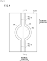
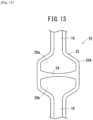
- the flow path sealing structure 10 is provided on the way of the flow path 16, and is equipped with a widened portion 20 that is wider than the flow paths 16 in the widthwise direction (a direction perpendicular to the flow path direction and the thickness direction of the resin sheets 12 and 14), and a weakly sealed portion 24 that is formed across the widened portion 20.
- the thickness of the widened portion 20 is substantially the same as the thickness of the flow paths 16, the thickness thereof is not limited to this feature.
- the widened portion 20 may be formed to be enlarged in the thickness direction of the flow paths 16 by locally changing the direction of the fusion bonded pattern in the vicinity of the widened portion 20.
- the widened portion 20 is formed in a circular shape as viewed in plan, and a widened seal portion 22 is formed along the peripheral edge part thereof.
- the widened seal portion 22 is constituted by a strong seal in which the resin sheets 12 and 14 are completely fusion bonded together.
- the widened seal portion 22 includes a semicircular arcuate portion 22a that constitutes one side portion, and a semicircular arcuate portion 22b that constitutes another side portion.
- the arcuate portion 22a is connected to one of the flow path sealed portions 16a of the flow paths 16.
- the arcuate portion 22b is connected to another one of the flow path sealed portions 16a of the flow paths 16.
- the width of the widened seal portion 22 itself may be approximately the same as the width of the flow path sealed portions 16a.
- a circular interior part 20c is formed at a portion surrounded by the widened seal portion 22.
- the interior part 20c is covered with the resin sheets 12 and 14 in the thickness direction.
- the resin sheets 12 and 14 bulge in a manner so as to separate away from each other in the thickness direction, and form a hollow portion or cavity.
- the interior part 20c communicates with the flow paths 16 at one end and another end thereof in the flow path direction.
- the interior part 20c is partitioned by the weakly sealed portion 24 in a liquid-tight and airtight manner into a first region 20a and a second region 20b.
- the first region 20a communicates with the flow path 16 on one end side in the flow path direction
- the second region 20b communicates with the flow path 16 on the other end side.
- the weakly sealed portion 24 is provided in close proximity to the center of the widened portion 20 in the flow path direction, and is formed across the widened portion 20 in the widthwise direction.
- the weakly sealed portion 24 is formed by fusion bonding the resin sheets 12 and 14, and as shown in FIG. 2B , the two resin sheets 12 and 14, which are superimposed on each other in the thickness direction, are fusion bonded in a state with an interface 25 left remaining therebetween.
- the weakly sealed portion 24 can be formed by being carried out under a condition in which the amount of input heat per unit area (sealing power) when the resin sheets 12 and 14 are fusion bonded is less than the amount of input heat per unit area when the strong seal is fusion bonded.
- the dimension of the weakly sealed portion 24 in the flow path direction (the vertical width in the drawing) is formed to be less than the width of the widened seal portion 22 or the flow path sealed portions 16a. More preferably, the weakly sealed portion 24 may have a concavely curved shape as viewed in plan, so that a dimension thereof in the flow path direction becomes smaller toward the center in the widthwise direction. Moreover, the weakly sealed portion 24 is not limited to being arranged in a direction perpendicular to the flow path direction, and may be inclined with respect to the flow path direction.
- the flow path sealing structure 10 according to the present embodiment is constituted in the manner described above. Next, operations thereof will be described below.
- the flow path sealing structure 10 is disposed on the way of the flow paths 16, and in an initial state, the weakly sealed portion 24 partitions one and another one of the flow paths 16 in a liquid-tight and airtight manner, whereby a fluid such as the medicinal solution and blood or the like is prevented from flowing.
- the flow path sealing structure 10 can be opened by supplying a pressurized fluid to the flow path sealing structure 10 through a bag-shaped container 40 or a pump that is connected to the flow paths 16. At that time, by the pressurized fluid flowing into the widened portion 20, the resin sheets 12 and 14 shown in FIG. 1B are pushed and spread apart in the thickness direction. As a result, at the weakly sealed portion 24, the interface 25 (see FIG. 2B ) between the resin sheets 12 and 14 is displaced in a manner so as to be peeled apart, and the flow path sealing structure 10 is opened.
- the flow path sealing structure 10 of the present embodiment is manufactured by a two-step fusion bonding process with differing amounts of input heat. More specifically, the flow path sealed portions 16a and the widened seal portion 22 are formed in the first fusion bonding step, and the weakly sealed portion 24 is formed in the second fusion bonding step. Prior to the first fusion bonding step, as shown in FIG. 3 , the resin sheet 12 and the resin sheet 14 are superimposed on each other in the thickness direction. In addition, the superimposed resin sheets 12 and 14 are transported inwardly between a lower mold 26 and an upper mold 28.
- the lower mold 26 includes pressing parts 26a that protrude from a main surface 26d, and cavities 26b and 26c formed between the pressing parts 26a.
- the pressing parts 26a are formed at a portion corresponding to the flow path sealed portions 16a of the flow paths 16, and the widened seal portion 22 of the widened portion 20.
- the cavity 26b is provided in a portion corresponding to the interior part 20c of the widened portion 20, and is formed in a recessed (concave) cylindrical shape.
- the cavity 26c is provided in a portion corresponding to the flow through portions 16b of the flow paths 16, and has a cross-section that is formed in a recessed (concave) arcuate shape.
- the upper mold 28 is formed vertically symmetrical with the lower mold 26, and includes pressing parts 28a that protrude from a main surface 28d, and cavities 28b and 28c formed between the pressing parts 28a.
- the pressing parts 28a are disposed in a portion of the lower mold 26 that faces toward the pressing parts 26a. Further, the cavities 28b and 28c are disposed in portions of the lower mold 26 that face respectively toward the cavities 26b and 26c.
- the lower mold 26 and the upper mold 28 press the pair of resin sheets 12 and 14. Consequently, portions of the resin sheets 12 and 14 that are sandwiched between the pressing parts 26a of the lower mold 26 and the pressing parts 28a of the upper mold 28 are placed in close contact with each other. Thereafter, pressurized air is injected between the resin sheets 12 and 14 and into the portion surrounded by the pressing parts 26a and 28a. Consequently, the resin sheet 12 bulges toward the cavities 28b, 28c of the upper mold 28. Further, the resin sheet 14 bulges toward the cavities 26b, 26c of the lower mold 26.
- high frequency electrical power is supplied between the upper mold 28 and the lower mold 26 to thereby perform the first fusion bonding step.
- the portions of the resin sheets 12 and 14 that are pressed from above and below by the pressing parts 26a of the lower mold 26 and the pressing parts 28a of the upper mold 28 are heated and fusion bonded together by the high frequency electrical power. Consequently, as shown in FIG. 4 , the flow paths 16, and the widened portion 20 where the pair of resin sheets 12 and 14 are fusion bonded together are formed. Further, the resin sheets 12 and 14 at the flow paths 16, and the widened portion 20 are shaped in a bulging shape by being fusion bonded while pressurized air is supplied thereto.
- the second fusion bonding step is performed.
- the second fusion bonding step is carried out using a lower mold 30 having a pressing part 30a at a portion corresponding to the weakly sealed portion 24, and an upper mold 32 having a pressing part 32a at a portion facing toward the pressing part 30a.
- the structure shown in FIG. 4 is arranged between the lower mold 30 and the upper mold 32.
- portions of the resin sheets 12 and 14 corresponding to the weakly sealed portion 24 are sandwiched between the pressing parts 30a and 32a.
- high frequency electrical power is supplied between the lower mold 30 and the upper mold 32 to thereby fusion bond the resin sheets 12 and 14 that are sandwiched between the pressing parts 30a and 32a.
- the second fusion bonding step is carried out under a condition in which the amount of input heat per unit area of the fusion bonded portion is less than in the first fusion bonding step. Consequently, the resin sheets 12 and 14 are fusion bonded in a state in which the interface 25 (see FIG. 2B ) is left remaining therebetween, and the weakly sealed portion 24 having an appropriate sealing strength is formed. In the manner described above, manufacturing of the flow path sealing structure 10 according to the present embodiment is completed.
- the diameter (width) of the widened portion 20 is variously changed, and an evaluation of the sealing strength of the weakly sealed portion 24 is performed when the electrical power (input heat) supplied in the second fusion bonding step is changed within a range of 20 to 70 W.
- the sealing strength of the weakly sealed portion 24 was evaluated by determining a pressure (opening pressure) when the weakly sealed portion 24 breaks upon supplying fluid from the one flow path 16.
- An appropriate opening pressure for the flow path sealing structure 10 of the present embodiment was evaluated as being appropriate when the lower limit thereof was within a range on the order of 0.1 MPa and an upper limit thereof was within a range on the order of 0.2 MPa.
- the opening pressure is less than a value in proximity to 0.1 MPa, since the sealing strength starts to become insufficient, a concern arises in that opening may easily occur in the case that an unintended load acts thereon during handling. Further, when the opening pressure exceeds a value in proximity to 0.2 MPa, it becomes difficult for opening to occur even if a pressure is applied thereto by the operator, and ease of handling tends to deteriorate.
- the diameter (width) of the widened portion 20 was set to 15.5 mm.
- the diameter (width) of the widened portion 20 was set to 13.5 mm.
- the diameter (width) of the widened portion 20 was set to 13.5 mm.
- the diameter (width) of the widened portion 20 was set to 9.5 mm.
- the width of the flow paths 16 was 2.8 mm, and the average dimension of the weakly sealed portion 24 in the flow path direction was 3 mm.
- FIG. 6 The results of Exemplary Embodiments 1 to 4 and the Comparative Example are shown in FIG. 6 .
- the sealing strength of the weakly sealed portion 24 gradually changes accompanying an increase in the electrical power supplied in the second fusion bonding step. Accordingly, in Exemplary Embodiments 1 to 4, due to the electrical power supplied in the second fusion bonding step, it was possible to confirm that the weakly sealed portions 24 of various sealing strengths can be formed, and the weakly sealed portion 24 having a desired sealing strength can be manufactured.
- the weakly sealed portion 24 may be controlled in a manner so that the sealing strength of the weakly sealed portion 24 becomes weaker than the sealing strength of the other portions. In this case, there is no need to perform fusion bonding twice with differing amounts of input heat, and the weakly sealed portion 24 can be formed by a single fusion bonding step.
- the flow path sealing structure 10 according to the present embodiment exhibits the following advantageous effects.
- the flow path sealing structure 10 of the present embodiment is characterized by the flow path sealing structure 10, which is disposed on the way of the flow path 16 formed by fusion bonding the pair of resin sheets 12 and 14 that are superimposed on each other, and includes the widened portion 20 surrounded by the widened seal portion 22 formed by fusion bonding the pair of resin sheets 12 and 14 around the periphery thereof, and the one end and the other end of which are in communication with the flow path 16, the widened portion 20 being formed to be wider than the flow path 16, and the weakly sealed portion 24 formed to extend in the widthwise direction in the widened portion 20, and which partitions the widened portion 20 in a liquid-tight and airtight manner into the first region 20a on the side of the one end and the second region 20b on the side of the other end, the weakly sealed portion 24 configured to be opened by increasing the internal pressure of the widened portion 20.
- the ability to control the sealing strength of the weakly sealed portion 24 can be improved, and it is possible to form the weakly sealed portion 24 with an appropriate sealing strength. Consequently, the flow path sealing structure 10, which is capable of reliably sealing the flow paths 16 and can be easily opened when necessary, can be integrally manufactured in the resin sheets 12 and 14 together with the flow paths 16.
- the weakly sealed portion 24 may be fusion bonded in a state in which the interface 25 is left remaining between the pair of resin sheets 12 and 14.
- the flow path sealing structure 10 can be easily opened.
- the dimension of the weakly sealed portion 24 in a direction (the flow path direction) perpendicular to the widthwise direction may be formed in a curving manner so as to become smaller toward the center in the widthwise direction.
- the resin sheets 12 and 14 adjacent to the weakly sealed portion 24 are likely to bulge in a manner so as to separate away from each other due to the pressure of the fluid, and the ability to control the sealing strength is further improved.
- the widened portion 20 may be formed in a circular shape as viewed in plan.
- the resin sheets 12 and 14 adjacent to the weakly sealed portion 24 become likely to bulge, and control of the sealing strength is facilitated.
- the pair of resin sheets 12 and 14 may bulge in a manner so as to separate away from each other in the thickness direction.
- the resin sheets 12 and 14 are likely to bulge when a pressure is applied thereto, control of the sealing strength is facilitated.
- the first region 20a and the second region 20b need not necessarily be made to bulge. In accordance with such constitution, if there is a bulge, stresses will continue to be applied to the weakly sealed portion 24, and there is a possibility that pealing apart may take place. By making the first region 20a and the second region 20b flat, application of stress to the sealed portion can be eliminated.
- the method of manufacturing a flow path sealing structure 10 includes the step of superimposing the pair of resin sheets 12 and 14 in the thickness direction, the first fusion bonding step of fusion bonding the pair of resin sheets 12 and 14 to thereby form the flow path 16, and the widened portion 20 disposed on the way of the flow path 16 and which is formed to be wider than the flow path 16, and the second fusion bonding step of fusion bonding the resin sheets 12 and 14 of the widened portion 20 to thereby form the weakly sealed portion 24 that crosses in the widthwise direction, wherein, in the second fusion bonding step, fusion bonding is carried out under a condition in which the amount of input heat per unit area is less than in the first fusion bonding step.
- the flow path sealing structure 10 since the method can be realized simply by adding the second fusion bonding step of forming the weakly sealed portion 24 to the first fusion bonding step of forming the flow paths 16, the flow path sealing structure 10 can be formed with a fewer number of process steps than in a conventional flow path sealing structure in which the assembly of separate members is required. Further, by providing the weakly sealed portion 24 in the widened portion 20, the weakly sealed portion 24 can be formed with an appropriate sealing strength.
- the resin sheets 12 and 14 may be in close contact with the interface 25 left remaining therebetween.
- the flow path sealing structure 10 which is capable of being reliably opened when needed is obtained.
- the constituent materials of the resin sheets 12 and 14 that constitute the weakly sealed portion 24 may be controlled.
- the weakly sealed portion 24 may be formed at the same time as the first fusion bonding step, and with the same amount of heat input per area as other seal portions. Further, in this case as well, in the second fusion bonding step, the weakly sealed portion 24 may be formed with a smaller amount of input heat.
- the bag-shaped container 40 includes a main body portion 41, the flow paths 16 that communicate with the main body portion 41, and the flow path sealing structure 10 disposed on the way of the flow paths 16.
- the bag-shaped container 40 for example, is a container for medical use in which a medicinal solution or the like is stored therein, and the flow paths 16 are used for introducing a liquid into the bag-shaped container 40, or for discharging the liquid from the bag-shaped container 40.
- the main body portion 41, the flow paths 16, and the flow path sealing structure 10 are integrally formed by the pair of resin sheets 12 and 14.
- structural features that are the same as those of the flow paths 16 and the flow path sealing structure 10 shown in FIG. 1A they are designated by the same reference numerals, and detailed description of such features is omitted.
- the main body portion 41 is formed in a substantially rectangular shape, and includes a peripheral edge sealed portion 44 formed by fusion bonding a peripheral edge part thereof, and an accommodating section 42 formed on an inner side of the peripheral edge sealed portion 44.
- the peripheral edge sealed portion 44 is constituted by a strong seal in which the resin sheets 12 and 14 are completely fusion bonded.
- the peripheral edge sealed portion 44 closes the peripheral edge part of the main body portion 41, together with being divided at a communicating section 46.
- the accommodating section 42 is formed between the pair of resin sheets 12 and 14, and in the portion that is sealed by the peripheral edge sealed portion 44.
- the accommodating section 42 communicates with the flow paths 16 at the communicating section 46. Liquid contents are accommodated in the accommodating section 42.
- a flow path formation unit 48 projects from one end of the main body portion 41.
- the flow path formation unit 48 is a portion in which the flow paths 16 and the flow path sealing structure 10 are formed, and is constituted by the resin sheets 12 and 14 which are integrally connected to the main body portion 41.
- the flow paths 16 communicate with the accommodating section 42, and the flow paths 16 are sealed by the flow path sealing structure 10.
- the flow path sealed portions 16a on both sides of the flow paths 16 are connected to the peripheral edge sealed portion 44 on both sides of the communicating section 46. In the flow path sealing structure 10, when the main body portion 41 is pressed, the weakly sealed portion 24 breaks and opens.
- an opening prevention member 50 is attached to the flow path formation unit 48.
- the opening prevention member 50 is disposed at a position overlapping the weakly sealed portion 24 of the flow path sealing structure 10, and by being placed in abutment from both sides in the thickness direction of the weakly sealed portion 24, the resin sheets 12 and 14 at a location in close proximity to the weakly sealed portion 24 are prevented from rising upward, and breakage of the weakly sealed portion 24 is prevented.
- the opening prevention member 50 is a clamp equipped with a pair of rod-shaped holding members 50a, and holds the resin sheets 12 and 14 by an elastic biasing force of the holding members 50a. In use, the opening prevention member 50 can be easily removed by pulling off the holding members 50a from the resin sheets 12 and 14. Moreover, it should be noted that the opening prevention member 50 is not limited to such an illustrated clamp, and may be constituted so as to press the weakly sealed portion 24 by being formed integrally with a packaging body in which the bag-shaped container 40 is accommodated.
- the pair of resin sheets 12 and 14 are prepared, and the resin sheets 12 and 14 are superimposed on each other in the thickness direction.
- the superimposed resin sheets 12 and 14 are sandwiched between a lower mold and an upper mold of a predetermined shape, and the portion shown in hatching in FIG. 8 is pressed.
- a first fusion bonding step is carried out in which high frequency electrical power is supplied between the lower mold and the upper mold to thereby fusion bond the portion shown in hatching, and thereby form the peripheral edge sealed portion 44, the flow path sealed portions 16a, and the widened seal portion 22.
- the first fusion bonding step is performed under a condition in which fusion takes place until the interface 25 between the resin sheets 12 and 14 disappears. Further, in the first fusion bonding step, as shown in the drawing, a nozzle 52 is inserted between the resin sheets 12 and 14, and by supplying high pressure air from the nozzle 52, fusion bonding is carried out while the portions surrounded by the peripheral edge sealed portion 44, the flow path sealed portions 16a, and the widened seal portion 22 are made to undergo bulging. The nozzle 52 is pulled out after fusion bonding of the other peripheral edge part is completed, and the portion where the nozzle 52 is inserted is fusion bonded to complete the first fusion bonding step.
- a trimming step of cutting off an excess portion of the resin sheets 12 and 14 is performed.
- the trimming step is performed by placing the structure shown in FIG. 8 inside a mold provided with a cutting blade, and cutting and removing the excess portion.
- cutting blades for cutting off the excess portion of the resin sheets 12 and 14 may be provided on the lower mold and the upper mold that were used in the first fusion bonding step, and simultaneously with the resin sheets 12 and 14 being pressed by the lower mold and the upper mold, the main body portion 41 and the flow path formation unit 48 may be formed into predetermined shapes.
- a medicinal solution injection step of injecting a medicinal solution into the accommodating section 42 via the flow paths 16 is performed.
- the medicinal solution injection step is not performed.
- a second fusion bonding step is performed in order to form the weakly sealed portion 24 in the widened portion 20.
- the second fusion bonding step can be performed by the same method that was described with reference to FIG. 5 . Consequently, as shown in FIG. 9 , the weakly sealed portion 24 is formed, and the flow path sealing structure 10 is completed.
- the accommodating section 42 is sealed by the flow path sealing structure 10. In accordance with the above procedure, the basic constitution of the bag-shaped container 40 is completed.
- an opening prevention member 50 is attached to a portion that overlaps the weakly sealed portion 24.
- the bag-shaped container 40 to which the opening prevention member 50 has been attached is inserted into an autoclave device, and autoclave sterilization is carried out.
- autoclave sterilization the internal pressure of the accommodating section 42 of the bag-shaped container 40 rises, however, the opening prevention member 50 prevents opening of the flow path sealing structure 10.
- the method of manufacturing the bag-shaped container 40 of the present embodiment is brought to an end.
- the bag-shaped container 40 of the present embodiment exhibits the following advantageous effects.
- the bag-shaped container 40 of the present embodiment is characterized by the bag-shaped container 40 including the peripheral edge sealed portion 44 obtained by fusion bonding the pair of resin sheets 12 and 14 that are superimposed on each other, the accommodating section 42 surrounded by the peripheral edge sealed portion 44, the flow path 16 formed by fusion bonding the pair of resin sheets 12 and 14 and which are placed in communication with the accommodating section 42, and the flow path sealing structure 10 disposed on the way of the flow path 16, the flow path sealing structure 10 including the widened portion 20 surrounded by the widened seal portion 22 formed by fusion bonding the pair of resin sheets 12 and 14 around the periphery thereof, and the one end and the other end of which are in communication with the flow path 16, the widened portion 20 being formed to be wider than the flow path 16, and the weakly sealed portion 24 formed to extend in the widthwise direction in the widened portion 20, and which partitions the widened portion 20 in a liquid-tight and airtight manner into the first region 20a on the side of the one end and the second region 20b on the
- the flow paths 16 and the flow path sealing structure 10 are formed integrally with the bag-shaped container 40, production efficiency is superior. Further, by being equipped with the flow path sealing structure 10 in which the weakly sealed portion 24 is provided in the widened portion 20, the ability to control the sealing strength is excellent.
- the weakly sealed portion 24 may be fusion bonded in a state in which the interface 25 (see FIG. 2B ) is left remaining between the pair of resin sheets 12 and 14.
- the flow path sealing structure 10 can be easily opened by pressing the bag-shaped container 40.
- the dimension of the weakly sealed portion 24 in a direction perpendicular to the widthwise direction may be formed in a curving manner so as to become smaller toward the center in the widthwise direction.
- the widened portion 20 may be formed in a circular shape as viewed in plan.
- the pair of resin sheets 12 and 14 may bulge so as to separate away from each other in the thickness direction.
- the resin sheets 12 and 14 at a location in close proximity to the weakly sealed portion 24 are likely to bulge, and the ability to control the sealing strength of the weakly sealed portion 24 is improved.
- the opening prevention member 50 that prevents the weakly sealed portion 24 from separating in the thickness direction. In accordance with this feature, even in the case that the internal pressure of the accommodating section 42 increases during autoclave sterilization, opening of the flow path sealing structure 10 can be prevented.
- the method of manufacturing the bag-shaped container 40 includes the step of superimposing the pair of resin sheets 12 and 14 in the thickness direction, the first fusion bonding step of fusion bonding the pair of resin sheets 12 and 14 to thereby form the accommodating section 42, the flow path 16, and the widened portion 20 disposed on the way of the flow path 16 and which is formed to be wider than the flow path 16, and the second fusion bonding step of fusion bonding the resin sheets 12 and 14 of the widened portion 20 to thereby form the weakly sealed portion 24 that crosses in the widthwise direction, wherein, in the second fusion bonding step, fusion bonding is carried out under a condition in which the amount of input heat per unit area is less than in the first fusion bonding step.
- the flow path sealing structure 10 can be added to the bag-shaped container 40 with a fewer number of process steps than in a conventional flow path sealing structure in which the assembly of separate members is required. Further, by providing the weakly sealed portion 24 in the widened portion 20, the weakly sealed portion 24 can be formed with an appropriate sealing strength.
- the resin sheets 12 and 14 may be fusion bonded with the interface 25 (see FIG. 2B ) left remaining therebetween.
- the flow path sealing structure 10 which is capable of being reliably opened when needed is obtained.
- the step of heat sterilizing (autoclave sterilizing) the accommodating section 42, the flow path 16, and the widened portion 20 after the second fusion bonding step may further be included the step of heat sterilizing (autoclave sterilizing) the accommodating section 42, the flow path 16, and the widened portion 20 after the second fusion bonding step, and the heat sterilization step may be performed by attaching to the weakly sealed portion 24 the opening prevention member 50 that prevents the weakly sealed portion 24 from separating in the thickness direction.
- the heat sterilization step may be performed by attaching to the weakly sealed portion 24 the opening prevention member 50 that prevents the weakly sealed portion 24 from separating in the thickness direction.
- the flow paths 16 and the flow path sealing structure 10 can be formed together with the bag-shaped container 40, simply by adding the second fusion bonding step of forming the weakly sealed portion 24 to the first fusion bonding step of forming the peripheral edge sealed portion 44 of the bag-shaped container 40. Consequently, the flow path sealing structure 10 can be formed in the bag-shaped container 40 with a fewer number of process steps than in a conventional flow path sealing structure in which the assembly of separate members is required. Further, by providing the weakly sealed portion 24 in the widened portion 20, the weakly sealed portion 24 can be formed with an appropriate sealing strength.
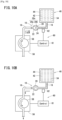
- the method of the present embodiment is performed using a transfer device 60 as shown in FIG. 10A .
- the transfer device 60 for example, is a device that constitutes a part of a blood sampling device or a centrifugal separation device, and by opening the flow path sealing structure 10 of the bag-shaped container 40 which has been set therein, is capable of transferring the fluid accommodated in the accommodating section 42.
- the transfer device 60 includes a pump 56, a control unit 61, and a sensor 62.
- the pump 56 for example, is a peristaltic pump, and is equipped with a rotor 58.
- the flow path 16 that extends from the bag-shaped container 40 is installed on the rotor 58 of the pump 56. By undergoing peristaltic motion, the rotor 58 is capable of transferring the fluid inside the flow paths 16.
- the sensor 62 for example, is an optical sensor, and detects a component of the fluid inside the flow paths 16.
- the sensor 62 may also be a pressure sensor that detects the internal pressure of the flow paths 16.
- the control unit 61 controls operation of the pump 56 based on the detection result of the sensor 62.
- Transferring of the fluid from the bag-shaped container 40 by the transfer device 60 is performed in the following manner. First, the flow paths 16 of the bag-shaped container 40 are set in the pump 56, and the opening prevention member 50 (see FIG. 7 ), which is attached to the flow path sealing structure 10, is removed.
- the pump 56 is operated to rotate the rotor 58 in the direction of the arrow. Consequently, a pressurized fluid (for example, air) is sent into the flow path sealing structure 10 via the flow paths 16.
- a pressurized fluid for example, air
- the resin sheets 12 and 14 in close proximity to the weakly sealed portion 24 bulge in a manner so as to be peeled apart, and the weakly sealed portion 24 is broken. Consequently, the flow path sealing structure 10 is opened.
- the sensor 62 detects a change in the fluid component, and based thereon, the control unit 61 detects the opening of the flow path sealing structure 10. When the opening of the flow path sealing structure 10 is detected, the control unit 61 reverses the direction in which the rotor 58 of the pump 56 rotates.
- the transfer device 60 of the present embodiment it is possible for opening of the flow path sealing structure 10 and transferring of the fluid in the bag-shaped container 40 to be carried out.
- the method of opening the flow path sealing structure 10 according to the present embodiment and the transfer method of transferring the fluid exhibit the following advantageous effects.
- the flow path sealing structure 10 is disposed on the way of the flow path 16 formed by fusion bonding the pair of resin sheets 12 and 14 that are superimposed on each other, and includes the widened portion 20 surrounded by the widened seal portion 22 formed by fusion bonding the pair of resin sheets 12 and 14 around the periphery thereof, and one end and another end of which are in communication with the flow path 16, the widened portion 20 being formed to be wider than the flow path 16, and the weakly sealed portion 24 formed to extend in the widthwise direction in the widened portion 20, and which partitions the widened portion 20 in a liquid-tight and airtight manner into the first region 20a on the side of the one end and the second region 20b on the side of the other end, the weakly sealed portion 24 configured to be opened by increasing the internal pressure of the widened portion 20, the method of opening the flow path sealing structure 10 including the step of connecting the pump 56 to the flow path 16, and the step of sending the pressurized fluid into
- the transfer method according to the present embodiment is a transfer method applied to the bag-shaped container 40, the bag-shaped container 40 including the peripheral edge sealed portion 44 obtained by fusion bonding the pair of resin sheets 12 and 14 that are superimposed on each other, the accommodating section 42 surrounded by the peripheral edge sealed portion 44, the flow path 16 formed by fusion bonding the pair of resin sheets 12 and 14 and which are placed in communication with the accommodating section 42, and the flow path sealing structure 10 disposed on the way of the flow path 16, the flow path sealing structure 10 including the widened portion 20 surrounded by the widened seal portion 22 formed by fusion bonding the pair of resin sheets 12 and 14 around the periphery thereof, and the one end and the other end of which are in communication with the flow path 16, the widened portion 20 being formed to be wider than the flow path 16, and the weakly sealed portion 24 formed to extend in the widthwise direction in the widened portion 20, and which partitions the widened portion 20 in a liquid-tight and airtight manner into the first region 20a on the side of the one end
- Such a transfer method includes the step of connecting the pump 56 to the flow path 16, the step of sending the pressurized fluid toward the flow path sealing structure 10 and into the accommodating section 42 through the pump 56, and causing the pair of resin sheets 12 and 14 that constitute the weakly sealed portion 24 of the flow path sealing structure 10 to separate, and the step of reversing the pump 56 and causing the fluid in the accommodating section 42 to flow out from the accommodating section 42.
- opening of the flow path sealing structure 10 of the bag-shaped container 40, and transferring of the fluid in the accommodating portion 42 can be performed without the need for human intervention.
- the blood bag system 70 serves as a system for centrifugally separating blood containing a plurality of components into a plurality of components having different specific gravities (for example, two components of a light specific gravity component and a heavy specific gravity component), and accommodating and storing the respective components in different bags.
- the blood bag system 70 according to the present embodiment is constituted so as to centrifugally separate the remaining blood components, in which white blood cells and blood platelets have been removed from whole blood, into two components of blood plasma and concentrated red blood cells, and to accommodate and store the plasma and the concentrated red blood cells by dividing them into different bags.
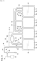
- the blood bag system 70 includes a blood collection unit 88 that collects blood from a donor, a blood collection bag 72 in which collected whole blood is accommodated, a preprocessing unit that removes predetermined blood components from the whole blood, a parent bag 74 and a child bag 76 in which remaining blood components from which predetermined components have been removed are centrifugally separated and divided into a plurality of blood components that are accommodated therein, and a medicinal solution bag 78 for supplying a red blood cell storage solution 92 to the parent bag 74.
- the blood collection unit 88 is equipped with tubes 102 and 104, a branch connector 100, a breakable member 94, a blood collection needle 96, and an initial flow blood bag 98.
- the branch connector 100 is equipped with first to third ports.
- the blood collection needle 96 is connected to the first port, the initial flow blood bag 98 is connected to the second port, and the third port is connected to the blood collection bag 72 via the breakable member 94 and the tube 104.
- the blood collection needle 96 has a needle tip that is punctured into the skin of the donor, and is a part into which blood from the donor flows when blood collection from the donor is carried out.
- the initial flow of blood when blood is collected flows through the second port of the branch connector 100, and is accommodated in the initial flow blood bag 98.
- the initial flow blood bag 98 accommodates a predetermined amount of the initial flow of blood.
- the tube 102 is connected to the third port of the branch connector 100, and the other end is connected to one end of the breakable member 94.
- the breakable member 94 is constituted in a manner so that the flow path is closed in an initial state, however, the flow path is opened by performing a breaking operation.
- the blood collection bag 72 is connected via the tube 104 to the other end of the breakable member 94.
- the breakable member 94 is subjected to the breaking operation after the initial flow of blood is collected in the initial flow blood bag 98.
- the whole blood collected from the donor flows into the blood collection bag 72 through the opened breakable member 94.
- the tube 104 is made from a thermoplastic resin or the like, and together with being fusion bonded and sealed by a tube sealer or the like, is constituted to be cut after the completion of blood collection.
- the tube 102 and a flow path 80a are connected to the blood collection bag 72.
- the flow path 80a communicates with an accommodating section 72b of the blood collection bag 72.
- the flow path sealing structure 10 is disposed on the way of the flow path 80a, and the flow path 80a is sealed by the flow path sealing structure 10 in an initial state.
- the preprocessing unit includes a filter 84 for removing predetermined cells, an inlet-side flow path 80a, and an outlet-side flow path 80b.
- the inlet-side flow path 80a and the outlet-side flow path 80b constitute a first flow path 80 connecting the blood collection bag 72 and a parent bag 74.
- the inlet-side flow path 80a is a flow path for transferring blood collected from the donor from the blood collection bag 72 to the filter 84.
- the outlet-side flow path 80b is a flow path for transferring the blood that has passed through the filter 84 to the parent bag 74.
- the outlet-side flow path 80b and the inlet-side flow path 80a are formed by fusion bonding the resin sheets 12 and 14, and are integrally connected to the blood collection bag 72.
- the filter 84 removes predetermined cells when the blood is transferred from the blood collection bag 72 to the parent bag 74.
- the filter 84 is a leukocyte removing filter.
- a filter medium made of a liquid-permeable porous body or a non-woven fabric can be used.
- the filter 84 may be constituted in a manner so as to also capture platelets.
- the filter 84 is disposed between the resin sheets 12 and 14, and is sealed on the inner side of a filter sealed portion 85 formed by being fusion bonded along a peripheral edge part thereof.
- the parent bag 74 serves both as a bag for accommodating the residual blood from which predetermined cells have been removed by the filter 84, and a bag for storing a sedimentation component (rich red blood cells) obtained by centrifugally separating blood.
- the parent bag 74 is provided with a peripheral edge sealed portion 74a where a peripheral edge part thereof is subjected to fusion bonding, and an accommodating section 74b is formed on the inner side thereof.
- the outlet-side flow path 80b and the second flow path 82 are connected to the upper end of the parent bag 74.
- the second flow path 82 is a flow path that is formed by fusion bonding the resin sheets 12 and 14, and is formed by being integrally connected to the parent bag 74 and the like.
- the second flow path 82 is connected to the parent bag 74, together with being connected to the child bag 76 and the medicinal solution bag 78 via a branching member 83.
- the flow path sealing structure 10 is provided respectively in the vicinity of the parent bag 74 and the medicinal solution bag 78.
- the child bag 76 serves as a bag for storing a supernatant component (blood plasma) obtained by subjecting the parent bag 74 to centrifugation.
- the second flow path 82 is connected to the upper end of the child bag 76.
- the child bag 76 is connected to the parent bag 74 via the second flow path 82.
- the medicinal solution bag 78 accommodates the red blood cell storage solution 92 that is supplied to the parent bag 74.
- the red blood cell storage solution 92 there may be used a MAP solution, a SAGM solution, an OPTISOL solution, or the like.
- the second flow path 82 and the tube 106 are connected to the upper end of the medicinal solution bag 78.
- the tube 106 is a tube for injecting the medicinal solution into the medicinal solution bag 78, and is subjected to fusion bonding and sealed by a sealer or the like.
- the blood collection bag 72, the parent bag 74, the child bag 76, and the medicinal solution bag 78 are separated from each other at cutting portions 86.
- the respective bags are integrally connected via the first flow path 80 and the second flow path 82.
- blood (whole blood) is accommodated in the blood collection bag 72 through the blood collection unit 88. Thereafter, the user cuts and seals the tube 104 with a sealer, and separates the blood collection unit 88. Next, an opening operation is carried out on the flow path sealing structure 10, and the blood components of the blood collection bag 72 are transferred to the parent bag 74. At this time, leukocytes and blood platelets are removed by the filter 84 from the blood that is transferred from the blood collection bag 72. Thereafter, by cutting and fusion bonding the outlet-side flow path 80b with a sealer, the user separates the blood collection bag 72 and the filter 84 from the parent bag 74.
- the parent bag 74, the child bag 76, and the medicinal solution bag 78 are set in the centrifugal separation device.
- a centrifugal force is applied to the parent bag 74 to thereby separate the blood inside the parent bag 74 into a supernatant component of blood plasma and a sedimentation component of red blood cells, together with transferring the supernatant component of the blood platelets through the second flow path 82 into the child bag 76.
- the centrifugal separation device automatically opens the flow path sealing structure 10 provided in the second flow path 82, and transfers the supernatant component. Thereafter, a part of the second flow path 82 that extends toward the child bag 76 via the branching member 83 is closed by a clamp.
- the red blood cell storage solution 92 in the medicinal solution bag 78 is transferred to the parent bag 74 through the second flow path 82, whereupon the centrifugation process for the blood components is completed.
- the pair of resin sheets 12 and 14 which are formed in a predetermined shape are prepared, and the resin sheets 12 and 14 are superimposed on each other in the thickness direction.
- the filter 84, the tubes 104 and 106, and the like be positioned and temporarily fixed at predetermined positions beforehand.
- a first fusion bonding step is performed, and the resin sheets 12 and 14 are subjected to fusion bonding with a strong seal. More specifically, fusion bonding is carried out on the peripheral edge sealed portions 72a, 74a, 76a, and 78a, the fusion bonded portion of the first flow path 80, the fusion bonded portion of the second flow path 82, and the widened seal portion 22 (see FIG. 1A ) of the flow path sealing structure 10.
- the first fusion bonding step as shown in FIG.
- the resin sheets 12 and 14 are sandwiched between the upper mold and the lower mold having a protruding portion at the fusion bonded portion, and while high pressure air is supplied to the region surrounded by the fusion bonded portion, fusion bonding is carried out by supplying high frequency electrical power to the lower mold and the upper mold.
- a second fusion bonding step is carried out in order to form the weakly sealed portion 24 of the flow path sealing structure 10.
- the second fusion bonding step can be performed by the method described with reference to FIG. 5 .
- the anticoagulant 90 is injected into the blood collection bag 72 via the tube 104.
- the breakable member 94 and the blood collection unit 88 are attached to the tube 104.
- the red blood cell storage solution 92 is injected into the medicinal solution bag 78 via the tube 106.
- the tube 106 is cut and sealed with a sealer.
- the basic constitution of the blood bag system 70 is completed. Thereafter, autoclave sterilization is carried out on the blood bag system 70.
- autoclave sterilization it is preferable to attach an opening prevention member 50 (see FIG. 7 ) in order to prevent opening of the flow path sealing structure 10.
- manufacturing of the blood bag system 70 is completed.
- the blood bag system 70 of the present embodiment exhibits the following advantageous effects.
- the blood bag system 70 is characterized by the blood bag system 70 including the blood collection bag 72 in which whole blood is collected, the parent bag 74 in which centrifugal separation of the whole blood is carried out, the child bag 76 in which a portion of the separated blood component is accommodated, the medicinal solution bag 78 in which the red blood cell storage solution 92 for the blood component is accommodated, the first flow path 80 configured to connect the blood collection bag 72 and the parent bag 74, and the second flow path 82 configured to connect the parent bag 74, the child bag 76, and the medicinal solution bag 78, wherein the blood collection bag 72, the parent bag 74, the child bag 76, the medicinal solution bag 78, the first flow path 80, and the second flow path 82 are integrally formed by fusion bonding the pair of resin sheets 12 and 14, and there is provided the flow path sealing structure 10 disposed in at least one of the paths of the first flow path 80 and the second flow path 82, the flow path sealing structure 10 including the widened portion 20 surrounded by the widened
- FIG. 12A a description will be given concerning an example in which the flow path sealing structure 10 is applied to a sample collecting structure 110 for a bag-shaped container 40A. Moreover, concerning constituent features that are the same as those of the flow path sealing structure 10 shown in FIG. 1A and the bag-shaped container 40 shown in FIG. 7 , they are designated by the same reference numerals, and detailed description of such features is omitted.
- the bag-shaped container 40A is equipped with the main body portion 41 to which a connection port 107, and the sample collecting structure 110 are connected to an upper end thereof, and is constituted to be capable of sampling with the sample collecting structure 110 a portion of the liquid accommodated in the accommodating section 42 of the main body portion 41.
- the bag-shaped container 40A is a container of a bag shape in which a pair of resin sheets 12 and 14 are superimposed on each other and fusion bonded at the peripheral edge sealed portion 44, and is capable of accommodating a liquid in the accommodating section 42 via the connection port 107 and a tube 108 that is connected to the connection port 107.
- the sample collecting structure 110 includes a sample container 114 in which a collected liquid is accommodated, and flow paths 116 that connect the sample container 114 and the bag-shaped container 40A.
- the sample container 114, the flow paths 116, and the flow path sealing structure 10 that constitute the sample collecting structure 110 are formed by the pair of resin sheets 12 and 14 that constitute the bag-shaped container 40A. More specifically, the sample collecting structure 110 is integrally connected to the bag-shaped container 40A.
- the sample container 114 is provided with a peripheral edge sealed portion 114a which is formed by fusion bonding the resin sheets 12 and 14 at a peripheral edge part thereof, and an accommodating section 114b is formed on the inner side of the peripheral edge sealed portion 114a.
- the tube 108 is sealed with a sealer and cut.
- the accommodating section 42 is pressed to apply a pressure to the flow path sealing structure 10 through the flow paths 116, thereby opening the flow path sealing structure 10.
- the accommodating section 42 is further pressed to thereby transfer the liquid accommodated in the accommodating section 42 to the sample container 114.
- the flow path 116 is cut while being sealed with a sealer, and as shown in FIG. 12B , the sample collecting structure 110 is separated from the main body portion 41. The sample collecting structure 110 is used for testing or analysis.
- the above described sample collecting structure 110 for the bag-shaped container 40A is manufactured by the following method.
- the pair of resin sheets 12 and 14 which are formed in a predetermined shape are prepared, and after the connection port 107 has been temporarily fixed thereto at a predetermined position, the resin sheets 12 and 14 are superimposed on each other. Thereafter, the first fusion bonding step is performed to thereby form the peripheral edge sealed portions 44 and 114a, the flow path sealed portions 116a, and the widened seal portion 22.
- the first fusion bonding step is performed under a condition in which a strong seal is formed.
- the second fusion bonding step is performed to thereby form the weakly sealed portion 24 in the flow path sealing structure 10.
- the second fusion bonding step can be performed by the same method that was described with reference to FIG. 5 .
- the tube 108 is connected to the connection port 107 of the bag-shaped container 40A, whereupon the bag-shaped container 40A is completed.
- the bag-shaped container 40A may be subjected to autoclave sterilization. In this case, it is preferable to attach the opening prevention member 50 (see FIG. 7 ) to the weakly sealed portion 24 of the flow path sealing structure 10.
- the weakly sealed portion 24 can be opened by the operator squeezing the bag to thereby raise the internal pressure.
- the sample collecting structure 110 for the bag-shaped container 40A according to the present embodiment exhibits the following advantageous effects.
- the sample collecting structure 110 for the bag-shaped container 40A includes the flow path 116 connected to the bag-shaped container 40A in which the accommodating section 42 is formed in the interior thereof, and which are placed in communication with the accommodating section 42, the sample container 114 connected to the bag-shaped container 40A via the flow path 116, and the flow path sealing structure 10 disposed on the way of the flow path 116 and configured to seal the flow path 116, wherein the flow path 116, the sample container 114, and the flow path sealing structure 110 are formed integrally with the bag-shaped container 40A by fusion bonding the pair of resin sheets 12 and 14.
- the flow path sealing structure 10 includes the widened portion 20 surrounded by the widened seal portion 22 formed by fusion bonding together the pair of resin sheets 12 and 14 around the periphery thereof, and the one end and the other end of which are in communication with the flow path 116, the widened seal portion 22 being formed to be wider than the flow path 116, and the weakly sealed portion 24 formed to extend in the widthwise direction in the widened portion 20, and which partitions the widened portion 20 in a liquid-tight and airtight manner into the first region 20a on the side of the one end and the second region 20b on the side of the other end, the weakly sealed portion 24 configured to be opened by increasing the internal pressure of the widened portion 20.
- sample collecting structure 110 of the bag-shaped container 40A since the sample collecting structure 110 which includes the flow path sealing structure 10 can be simultaneously formed integrally with the pair of resin sheets 12 and 14 that constitute the bag-shaped container 40A, manufacturing costs can be suppressed.
- an example of the widened portion 20 of the flow path sealing structure 10 was described as being formed in a circular shape as viewed in plan, however, the embodiments are not limited to this feature.
- a widened portion 20A that is formed in a rectangular shape as viewed in plan may also be provided.
- Such a widened portion 20A is formed in a rectangular shape in which the dimension thereof in the flow path direction extends longer than the dimension in the widthwise direction, and the weakly sealed portion 24 extends in the widthwise direction at a central part in the flow path direction. Even if the widened portion 20A of the present embodiment is applied to the flow path sealing structure 10, the same advantages and effects can be obtained.
Landscapes
- Mechanical Engineering (AREA)
- Engineering & Computer Science (AREA)
- Health & Medical Sciences (AREA)
- Pharmacology & Pharmacy (AREA)
- Life Sciences & Earth Sciences (AREA)
- Animal Behavior & Ethology (AREA)
- General Health & Medical Sciences (AREA)
- Public Health (AREA)
- Veterinary Medicine (AREA)
- Physics & Mathematics (AREA)
- Thermal Sciences (AREA)
- Hematology (AREA)
- Fluid Mechanics (AREA)
- Medical Preparation Storing Or Oral Administration Devices (AREA)
- External Artificial Organs (AREA)
Claims (15)
- Strömungspfad-Dichtungsstruktur (10), die auf einem Weg eines Strömungspfads (16) vorgesehen ist, der durch Schmelzverbinden eines Paars von übereinanderliegenden Harzlagen (12 und 14) ausgebildet ist, wobei die Strömungspfad-Dichtungsstruktur aufweist:einen aufgeweiteten Abschnitt (20), der von einem aufgeweiteten Dichtungsabschnitt (22) umgeben ist, der durch Schmelzverbinden des Paars von Harzlagen um einen Umfang davon herum ausgebildet ist, und dessen eines Ende und dessen anderes Ende mit dem Strömungspfad in Verbindung stehen, wobei der aufgeweitete Abschnitt (20) so ausgebildet ist, dass er weiter ist als der Strömungspfad; undeinem schwach abgedichteten Abschnitt (24), der so konfiguriert ist, dass er durch Erhöhen eines Innendrucks des aufgeweiteten Abschnitts geöffnet wird,dadurch gekennzeichnet, dassder schwach abgedichtete Abschnitt (24) so ausgebildet ist, dass er sich in einer Richtung der Breite nach in dem aufgeweiteten Abschnitt erstreckt, und den aufgeweiteten Abschnitt auf flüssigkeitsdichte und luftdichte Weise in einen ersten Bereich (20a) auf einer Seite des einen Endes und einen zweiten Bereich (20b) auf einer Seite des anderen Endes unterteilt.
- Strömungspfad-Dichtungsstruktur gemäß Anspruch 1, wobei der schwach abgedichtete Abschnitt (24) in einem Zustand schmelzverbunden ist, in dem eine Grenzfläche (25) zwischen dem Paar von Harzlagen verbleibt, und/oder wobei sich ein Material der Harzlagen, die den schwach abgedichteten Abschnitt (24) bilden, von einem Material der Harzlagen unterscheidet, die den aufgeweiteten Dichtungsabschnitt (22) bilden,und/oder wobei eine Abmessung des schwach abgedichteten Abschnitts (24) in einer Richtung senkrecht zur Breitenrichtung gekrümmt ausgebildet ist, so dass sie in Breitenrichtung zu einem Mittelpunkt hin kleiner wird,und/oder wobei der aufgeweitete Abschnitt in der Draufsicht kreisförmig ausgebildet ist, und/oder wobei sich das Paar aus Harzlagen an dem aufgeweiteten Abschnitt so wölbt, dass sie sich in Dickenrichtung voneinander trennen.
- Beutelförmiger Behälter (40) mit einem Abschnitt (44) mit abgedichteter Umfangskante, der durch Schmelzverbinden eines übereinanderliegenden Paars von Harzlagen erhalten wird,einem Aufnahmeabschnitt (42), der von dem Abschnitt mit abgedichteter Umfangskante umgeben ist,einem Strömungspfad, der durch Schmelzverbinden des Paars von Harzlagen ausgebildet wird und der in Verbindung mit dem Aufnahmeabschnitt steht, und einer Dichtungsstruktur für den Strömungspfad, die auf einem Weg des Strömungspfads vorgesehen ist;wobei die Dichtungsstruktur des Strömungspfads hat:einen aufgeweiteten Abschnitt, der von einem aufgeweiteten Dichtungsabschnitt (22) umgeben ist, der durch Schmelzverbinden des Paars von Harzlagen um einen Umfang davon herum ausgebildet ist, und dessen eines Ende und dessen anderes Ende mit dem Strömungspfad in Verbindung stehen, wobei der aufgeweitete Abschnitt breiter als der Strömungspfad ausgebildet ist; undeinen schwach abgedichteten Abschnitt (24), der so konfiguriert ist, dass er durch Erhöhen eines Innendrucks des aufgeweiteten Abschnitts geöffnet wird,dadurch gekennzeichnet, dassder schwach abgedichtete Abschnitt (24) so ausgebildet ist, dass er sich in einer Richtung der Breite nach in dem aufgeweiteten Abschnitt erstreckt, und den aufgeweiteten Abschnitt auf flüssigkeitsdichte und luftdichte Weise in einen ersten Bereich (20a) auf einer Seite des einen Endes und einen zweiten Bereich (20b) auf einer Seite des anderen Endes unterteilt.
- Beutelförmiger Behälter gemäß Anspruch 3, wobei der schwach versiegelte Abschnitt (24) in einem Zustand schmelzverbunden ist, in dem eine Grenzfläche zwischen dem Paar von Harzlagen verbleibt
oder wobei sich ein Material der Harzlagen, die den schwach versiegelten Abschnitt (24) bilden, von einem Material der Harzlagen unterscheidet, die den aufgeweiteten Versiegelungsabschnitt (22) bilden. - Beutelförmiger Behälter gemäß Anspruch 4, wobei eine Abmessung des schwach abgedichteten Abschnitts (24) in einer Richtung senkrecht zur Breitenrichtung gekrümmt ausgebildet ist, so dass sie in Breitenrichtung zu einem Mittelpunkt hin kleiner wird,und/oder wobei der aufgeweitete Abschnitt in Draufsicht kreisförmig ausgebildet ist und/oder wobei sich an dem aufgeweiteten Abschnitt das Paar von Harzlagen so wölbt, dass sie sich in einer Richtung der Dicke voneinander trennen,und/oder ferner mit einem Öffnungsverhinderungselement (50), das so konfiguriert ist, dass es verhindert, dass sich der schwach abgedichtete Abschnitt in einer Richtung der Dicke trennt.
- Verfahren zur Herstellung einer Strömungspfad-Abdichtungsstruktur, mit:einem Schritt des Übereinanderlegens eines Paars von Harzlagen in einer Richtung der Dicke nach;einem ersten Schmelzverbindungsschritt des Schmelzverbindens des Paars von Harzlagen, um dadurch einen Strömungspfad auszubilden, und einen aufgeweiteten Abschnitt, der auf einem Weg des Strömungspfads vorgesehen ist und breiter als der Strömungspfad ausgebildet ist; undeinem zweiten Schmelzverbindungsschritt des Schmelzverbindens der Harzlagen des aufgeweiteten Abschnitts, um dadurch einen schwach abgedichteten Abschnitt (24) auszubilden, der eine Richtung der Breite nach schneidet;wobei in dem zweiten Schmelzverbindungsschritt das Schmelzverbinden unter einer Bedingung durchgeführt wird, bei der eine Menge an zugeführter Wärme pro Flächeneinheit geringer ist als in dem ersten Schmelzverbindungsschritt,dadurch gekennzeichnet, dassder schwach abgedichtete Abschnitt (24) so ausgebildet ist, dass er sich in einer Richtung der Breite nach in dem aufgeweiteten Abschnitt erstreckt.
- Verfahren zur Herstellung einer Strömungspfad-Dichtungsstruktur gemäß Anspruch 6, wobei in dem schwach abgedichteten Abschnitt (24) die Harzlagen in enger Berührung mit einer dazwischen verbleibenden Grenzfläche stehen und/oder wobei sich ein Material der Harzlagen, die den schwach abgedichteten Abschnitt (24) bilden, von einem Material der Harzlagen unterscheidet, die den aufgeweiteten Dichtungsabschnitt (22) bilden.
- Verfahren zur Herstellung einer Strömungspfad-Dichtungsstruktur mit:einem Schritt des Übereinanderlegens in Richtung der Dicke eines Paars von Harzlagen, wobei ein Abschnitt, in dem ein schwach abgedichteter Abschnitt (24) ausgebildet werden soll, aus einem anderen Material besteht;einem Schmelzverbindungsschritt des Schmelzverbindens des Paars von Harzlagen, um dadurch einen Strömungspfad und einen aufgeweiteten Abschnitt auszubilden, der auf einem Weg des Strömungspfads vorgesehen ist und breiter als der Strömungspfad ausgebildet ist; undeinen Schmelzverbindungsschritt des Schmelzverbindens der Harzlagen des aufgeweiteten Abschnitts, um dadurch den schwach abgedichteten Abschnitt (24) auszubilden, der eine Richtung der Breite nach schneidet;wobei der Überlagerungsschritt und die Schmelzverbindungsschritte gleichzeitig durchgeführt werden,dadurch gekennzeichnet, dassder schwach abgedichtete Abschnitt (24) so ausgebildet ist, dass er sich in einer Richtung der Breite in dem aufgeweiteten Abschnitt erstreckt.
- Verfahren zur Herstellung eines beutelförmigen Behälters, mit:einem Schritt des Übereinanderlegens eines Paars von Harzlagen in Richtung der Dicke;einem ersten Schmelzverbindungsschritt des Schmelzverbindens des Paars von Harzlagen, um dadurch einen Aufnahmeabschnitt, einen Strömungspfad und einen aufgeweiteten Abschnitt auszubilden, der auf dem Weg des Strömungspfads vorgesehen ist und weiter als der Strömungspfad ausgebildet ist; undeinem zweiten Schmelzverbindungsschritt des Schmelzverbindens der Lagen des Harzes des aufgeweiteten Abschnitts, um dadurch einen schwach abgedichteten Abschnitt (24) auszubilden, der in einer Richtung der Breite nach schneidet;wobei in dem zweiten Schmelzverbindungsschritt das Schmelzverbinden unter einer Bedingung ausgeführt wird, bei der eine Menge an zugeführter Wärme pro Flächeneinheit geringer ist als in dem ersten Schmelzverbindungsschritt,dadurch gekennzeichnet, dassder schwach abgedichtete Abschnitt (24) so ausgebildet ist, dass er sich in einer Richtung der Breite nach in dem aufgeweiteten Abschnitt erstreckt.
- Verfahren zur Herstellung eines beutelförmigen Behälters gemäß Anspruch 9, wobei der schwach abgedichtete Abschnitt (24) mit einer verbleibenden Grenzfläche zwischen den Lagen aus Harz schmelzverbunden wird und/oder ferner einen Schritt der Hitzesterilisation des Aufnahmeabschnitts, des Strömungspfads und des aufgeweiteten Abschnitts nach dem zweiten Schmelzverbindungsschritt aufweist, wobei der Schritt des Hitzesterilisierens durchgeführt wird, indem an dem schwach abgedichteten Abschnitt ein Öffnungsverhinderungselement angebracht wird, das so konfiguriert ist, dass es verhindert, dass sich der schwach abgedichtete Abschnitt in Richtung der Dicke nach trennt.
- Verfahren zur Herstellung eines beutelförmigen Behälters, mit:einem Schritt des Übereinanderlegens in Richtung der Dicke nach einem Paar von Harzlagen, wobei ein Abschnitt, in dem ein schwach abgedichteter Abschnitt (24) ausgebildet werden soll, aus einem anderen Material hergestellt ist;einem ersten Schmelzverbindungsschritt des Schmelzverbindens des Paars von Harzlagen, um dadurch einen Aufnahmeabschnitt, einen Strömungspfad und einen aufgeweiteten Abschnitt auszubilden, der auf dem Weg des Strömungspfads vorgesehen ist und weiter als der Strömungspfad ausgebildet ist; undeinem zweiten Schmelzverbindungsschritt des Schmelzverbindens der Harzlagen des aufgeweiteten Abschnitts, um dadurch einen schwach abgedichteten Abschnitt (24) auszubilden, der eine Richtung der Breite nach schneidet;wobei der zweite Schmelzverbindungsschritt gleichzeitig mit dem ersten Schmelzverbindungsschritt durchgeführt wird,dadurch gekennzeichnet, dassder schwach abgedichtete Abschnitt (24) so ausgebildet ist, dass er sich in einer Richtung der Breite nach in dem aufgeweiteten Abschnitt erstreckt.
- Verfahren zum Öffnen einer Strömungspfad-Abdichtungsstruktur, wobei
die Strömungspfad-Abdichtungsstruktur auf einem Weg eines Strömungspfads vorgesehen ist, der durch Schmelzverbinden eines Paars von übereinanderliegenden Harzlagen ausgebildet ist, und mit einem aufgeweiteten Abschnitt, der von einem aufgeweiteten Dichtungsabschnitt (22) umgeben ist, der durch Schmelzverbinden des Paars von Harzlagen um einen Umfang davon herum ausgebildet ist, und dessen eines Ende und dessen anderes Ende mit dem Strömungspfad in Verbindung stehen, wobei der aufgeweitete Abschnitt breiter als der Strömungspfad ausgebildet ist, und mit einem schwach abgedichteten Abschnitt (24), der so konfiguriert ist, dass er durch Erhöhen eines Innendrucks des aufgeweiteten Abschnitts geöffnet wird, wobei das Verfahren zum Öffnen der Strömungspfad-Dichtungsstruktur umfasst:einen Schritt, bei dem eine Pumpe (56) mit dem Strömungspfad verbunden wird; undeinen Schritt, bei dem ein unter Druck stehendes Fluid durch die Pumpe in den aufgeweiteten Abschnitt geleitet wird und das Paar von Harzlagen, die den schwach abgedichteten Abschnitt bilden, getrennt werden,dadurch gekennzeichnet, dassder schwach abgedichtete Abschnitt (24) so ausgebildet ist, dass er sich in einer Richtung der Breite nach in dem aufgeweiteten Abschnitt erstreckt, und den aufgeweiteten Abschnitt auf flüssigkeitsdichte und luftdichte Weise in einen ersten Bereich (20a) auf einer Seite des einen Endes und einen zweiten Bereich (20b) auf einer Seite des anderen Endes unterteilt. - Übertragungsverfahren zum Übertragen eines Fluids aus einem beutelförmigen Behälter mit einem durch Schmelzverbinden eines Paars von übereinanderliegenden Harzlagen erhaltenen, umlaufend abgedichteten Abschnitt, einem von dem umlaufend abgedichteten Abschnitt (44) umgebenen Aufnahmeabschnitt, einem durch Schmelzverbinden des Paars von Harzlagen ausgebildeten Strömungspfad, der mit dem Aufnahmeabschnitt in Verbindung steht, und einer auf einem Weg des Strömungspfads vorgesehenen Strömungspfad-Dichtungsstruktur, die Dichtungsstruktur des Strömungspfads hat einen aufgeweiteten Abschnitt, der von einem aufgeweiteten Dichtungsabschnitt (22) umgeben ist, der durch Schmelzverbinden des Paars von Harzlagen um einen Umfang davon herum ausgebildet ist, und ein Ende und ein anderes Ende davon stehen in Verbindung mit dem Strömungspfad, wobei der aufgeweitete Abschnitt breiter als der Strömungspfad ausgebildet ist, und einen schwach abgedichteten Abschnitt (24), der so konfiguriert ist, dass er durch Erhöhen eines Innendrucks des aufgeweiteten Abschnitts geöffnet wird, wobei das Übertragungsverfahren umfasst:einen Schritt, bei dem eine Pumpe mit dem Strömungspfad verbunden wird;einen Schritt, bei dem ein unter Druck stehendes Fluid durch die Pumpe in Richtung der Dichtungsstruktur des Strömungspfads und in den Aufnahmeabschnitt geschickt wird und das Paar von Harzlagen, die den schwach abgedichteten Abschnitt der Dichtungsstruktur des Strömungspfads bilden, getrennt wird; undeinen Schritt, bei dem die Pumpe umgekehrt wird und das Fluid im Aufnahmeabschnitt aus dem Aufnahmeabschnitt fließt,dadurch gekennzeichnet, dassder schwach abgedichtete Abschnitt (24) so ausgebildet ist, dass er sich in einer Richtung der Breite nach in dem aufgeweiteten Abschnitt erstreckt, und den aufgeweiteten Abschnitt auf flüssigkeitsdichte und luftdichte Weise in einen ersten Bereich (20a) auf einer Seite des einen Endes und einen zweiten Bereich (20b) auf einer Seite des anderen Endes unterteilt.
- Blutbeutelsystem (70) mit:einem Blutentnahmebeutel (72), in dem Vollblut gesammelt wird;einem Hauptbeutel (74), in dem eine Zentrifugaltrennung des Vollbluts durchgeführt wird;einem Nebenbeutel (76), in dem ein Abschnitt eines abgetrennten Blutbestandteils untergebracht wird;einem Beutel (78) für medizinische Lösungen, in dem eine Aufbewahrungslösung für das Bauteil untergebracht ist;einem ersten Strömungspfad (80), der so konfiguriert ist, dass er den Blutentnahmebeutel (72) und den Hauptbeutel (74) verbindet; undeinem zweiten Strömungspfad (82), der so konfiguriert ist, dass er den Hauptbeutel (74), den Nebenbeutel und den Beutel (78) für medizinische Lösungen verbindet;wobei der Blutsammelbeutel (72), der Hauptbeutel (74), der Nebenbeutel (76), der Beutel für die medizinische Lösung (78), der erste Strömungspfad (80) und der zweite Strömungspfad (82) einstückig ausgebildet sind, indem ein Paar aus Harzlagen schmelzverbunden wird; undeine Strömungspfad-Dichtungsstruktur bereitgestellt ist, die in mindestens einem der Wege des ersten Strömungspfads und des zweiten Strömungspfads vorgesehen ist, wobei die Strömungspfad-Dichtungsstruktureinen aufgeweiteten Abschnitt hat, der von einem aufgeweiteten Dichtungsabschnitt (22) umgeben ist, der durch Schmelzverbinden des Paars aus Harzlagen um einen Umfang davon herum ausgebildet ist, und dessen eines Ende und dessen anderes Ende mit dem ersten Strömungspfad oder dem zweiten Strömungspfad in Verbindung stehen, wobei der aufgeweitete Abschnitt breiter als der Strömungspfad ausgebildet ist; undeinen schwach abgedichteten Abschnitt (24), der so konfiguriert ist, dass er durch Erhöhen eines Innendrucks des aufgeweiteten Abschnitts geöffnet wird,dadurch gekennzeichnet, dassder schwach abgedichtete Abschnitt (24) so ausgebildet ist, dass er sich in einer Richtung der Breite nach in dem aufgeweiteten Abschnitt erstreckt, und den aufgeweiteten Abschnitt auf flüssigkeitsdichte und luftdichte Weise in einen ersten Bereich (20a) auf einer Seite des einen Endes und einen zweiten Bereich (20b) auf einer Seite des anderen Endes unterteilt.
- Probensammelstruktur (110) für einen beutelförmigen Behälter miteinem Strömungspfad (116), der mit dem beutelförmigen Behälter (40A) verbunden ist, in dessen Innerem ein Aufnahmeabschnitt (42) ausgebildet ist, und der in Verbindung mit dem Aufnahmeabschnitt steht, einen Probenbehälter (114), der mit dem beutelförmigen Behälter über den Strömungspfad verbunden ist, und eine Strömungspfad-Dichtungsstruktur, die auf einem Weg des Strömungspfads vorgesehen und so konfiguriert ist, dass sie den Strömungspfad abdichtet, wobei der Strömungspfad, der Probenbehälter und die Strömungspfad-Dichtungsstruktur einstückig mit dem beutelförmigen Behälter durch Schmelzverbinden eines Paars von Lagen aus Harz ausgebildet sind;wobei die Strömungspfad-Dichtungsstruktur hat:einen aufgeweiteten Abschnitt, der von einem aufgeweiteten Dichtungsabschnitt (22) umgeben ist, der durch Schmelzverbinden des Paars aus Harzlagen um einen Umfang davon herum ausgebildet ist, und dessen eines Ende und dessen anderes Ende mit dem Strömungspfad in Verbindung stehen, wobei der aufgeweitete Abschnitt weiter als der Strömungspfad ausgebildet ist; undeinen schwach abgedichteten Abschnitt (24), der so konfiguriert ist, dass er durch Erhöhen eines Innendrucks des aufgeweiteten Abschnitts geöffnet wird,dadurch gekennzeichnet, dassder schwach abgedichtete Abschnitt (24) so ausgebildet ist, dass er sich in einer Richtung der Breite nach in dem aufgeweiteten Abschnitt erstreckt, und den aufgeweiteten Abschnitt auf flüssigkeitsdichte und luftdichte Weise in einen ersten Bereich (20a) auf einer Seite des einen Endes und einen zweiten Bereich (20b) auf einer Seite des anderen Endes unterteilt.
Applications Claiming Priority (2)
| Application Number | Priority Date | Filing Date | Title |
|---|---|---|---|
| JP2019170097 | 2019-09-19 | ||
| PCT/JP2020/034035 WO2021054212A1 (en) | 2019-09-19 | 2020-09-09 | Flow path sealing structure, bag-shaped container, and method of manufacturing the same |
Publications (2)
| Publication Number | Publication Date |
|---|---|
| EP4021370A1 EP4021370A1 (de) | 2022-07-06 |
| EP4021370B1 true EP4021370B1 (de) | 2025-04-23 |
Family
ID=72670780
Family Applications (1)
| Application Number | Title | Priority Date | Filing Date |
|---|---|---|---|
| EP20781639.8A Active EP4021370B1 (de) | 2019-09-19 | 2020-09-09 | Dichtungsstruktur für den fliessweg, beutelförmiger behälter und verfahren zur herstellung desselben |
Country Status (4)
| Country | Link |
|---|---|
| US (1) | US12319008B2 (de) |
| EP (1) | EP4021370B1 (de) |
| JP (1) | JP7367179B2 (de) |
| WO (1) | WO2021054212A1 (de) |
Families Citing this family (1)
| Publication number | Priority date | Publication date | Assignee | Title |
|---|---|---|---|---|
| EP4486660A4 (de) * | 2022-03-02 | 2026-03-04 | Becton Dickinson Co | Verpackung zur terminalen sterilisation |
Family Cites Families (7)
| Publication number | Priority date | Publication date | Assignee | Title |
|---|---|---|---|---|
| JPH06105890A (ja) | 1992-09-30 | 1994-04-19 | Terumo Corp | バッグ連結体 |
| JP2006043405A (ja) * | 2004-07-01 | 2006-02-16 | Otsuka Pharmaceut Factory Inc | 医療用バッグ |
| DE202005004135U1 (de) | 2005-03-11 | 2005-05-19 | Klocke Verpackungs-Service Gmbh | Mehrkomponentenverpackung mit Applikator |
| JP4905643B2 (ja) * | 2005-12-06 | 2012-03-28 | 味の素株式会社 | 複室容器 |
| ATE551986T1 (de) * | 2006-11-06 | 2012-04-15 | Ajinomoto Kk | Mehrkammer-behälter |
| WO2012175436A1 (en) * | 2011-06-22 | 2012-12-27 | Gambro Lundia Ab | Container with sub-chambers separated by peelable seal |
| JP6997022B2 (ja) | 2018-03-23 | 2022-01-17 | 東京瓦斯株式会社 | 水素製造制御システム |
-
2020
- 2020-09-09 EP EP20781639.8A patent/EP4021370B1/de active Active
- 2020-09-09 WO PCT/JP2020/034035 patent/WO2021054212A1/en not_active Ceased
- 2020-09-09 JP JP2022508768A patent/JP7367179B2/ja active Active
-
2022
- 2022-03-17 US US17/697,602 patent/US12319008B2/en active Active
Also Published As
| Publication number | Publication date |
|---|---|
| JP7367179B2 (ja) | 2023-10-23 |
| WO2021054212A1 (en) | 2021-03-25 |
| US20220203628A1 (en) | 2022-06-30 |
| JP2022548486A (ja) | 2022-11-21 |
| US12319008B2 (en) | 2025-06-03 |
| EP4021370A1 (de) | 2022-07-06 |
Similar Documents
| Publication | Publication Date | Title |
|---|---|---|
| KR101510084B1 (ko) | 복실 용기 | |
| JP4317592B2 (ja) | 無菌の医療溶液を収容する容器および無菌の医療溶液を形成するための混合方法 | |
| US3064647A (en) | Blood component separation method and apparatus | |
| EP0596497B1 (de) | Beutel für mindestens zwei getrennt aufzubewahrende und zu mischende Substanzen | |
| KR102375726B1 (ko) | 의료 액체용 앰플 및 앰플의 제조 방법 | |
| KR20090079220A (ko) | 복실 용기 | |
| TW201138754A (en) | Filling | |
| JPS63309263A (ja) | 輸液バッグ | |
| EP3687594B1 (de) | System zum sammeln von biologischen komponenten und verfahren zum betrieb eines systems zum sammeln von biologischen komponenten | |
| JP5057172B2 (ja) | 複室容器 | |
| US12319008B2 (en) | Flow path sealing structure, bag-shaped container, and method of manufacturing the same | |
| EP0077189B1 (de) | Infusionsvorrichtung | |
| JP6040307B2 (ja) | 赤血球保存液、保存液収納容器、赤血球保存液の製造方法および血液バッグシステム | |
| JPH07328099A (ja) | バッグ連結体および血液成分の分離・移送方法 | |
| US5564279A (en) | Freezing bags | |
| JP3220750B2 (ja) | 血液成分を分離する際に使用される血液袋 | |
| CN114929460A (zh) | 剥离密封管封闭结构 | |
| WO2024102230A1 (en) | Bag closure and container system for medical liquids incorporating same | |
| JP3221701B2 (ja) | 体液バッグ | |
| JPH07136243A (ja) | 血液処理方法 | |
| JP2555452B2 (ja) | 血液バッグ | |
| JPH06105890A (ja) | バッグ連結体 | |
| JP4365948B2 (ja) | 輸液バッグ | |
| JP3126448B2 (ja) | 血漿採取回路 | |
| EP3993848B1 (de) | Blutbeutelsystem und verfahren zu seiner herstellung |
Legal Events
| Date | Code | Title | Description |
|---|---|---|---|
| STAA | Information on the status of an ep patent application or granted ep patent |
Free format text: STATUS: UNKNOWN |
|
| STAA | Information on the status of an ep patent application or granted ep patent |
Free format text: STATUS: THE INTERNATIONAL PUBLICATION HAS BEEN MADE |
|
| PUAI | Public reference made under article 153(3) epc to a published international application that has entered the european phase |
Free format text: ORIGINAL CODE: 0009012 |
|
| STAA | Information on the status of an ep patent application or granted ep patent |
Free format text: STATUS: REQUEST FOR EXAMINATION WAS MADE |
|
| 17P | Request for examination filed |
Effective date: 20220331 |
|
| AK | Designated contracting states |
Kind code of ref document: A1 Designated state(s): AL AT BE BG CH CY CZ DE DK EE ES FI FR GB GR HR HU IE IS IT LI LT LU LV MC MK MT NL NO PL PT RO RS SE SI SK SM TR |
|
| DAV | Request for validation of the european patent (deleted) | ||
| DAX | Request for extension of the european patent (deleted) | ||
| REG | Reference to a national code |
Free format text: PREVIOUS MAIN CLASS: A61J0001140000 Ipc: A61J0001100000 Ref country code: DE Ref legal event code: R079 Ref document number: 602020050016 Country of ref document: DE |
|
| GRAP | Despatch of communication of intention to grant a patent |
Free format text: ORIGINAL CODE: EPIDOSNIGR1 |
|
| STAA | Information on the status of an ep patent application or granted ep patent |
Free format text: STATUS: GRANT OF PATENT IS INTENDED |
|
| RIC1 | Information provided on ipc code assigned before grant |
Ipc: A61M 5/14 20060101ALN20241216BHEP Ipc: B29C 65/82 20060101ALI20241216BHEP Ipc: B29C 65/76 20060101ALI20241216BHEP Ipc: B29C 65/04 20060101ALI20241216BHEP Ipc: B29C 65/02 20060101ALI20241216BHEP Ipc: A61J 1/20 20060101ALI20241216BHEP Ipc: A61J 1/14 20060101ALI20241216BHEP Ipc: A61J 1/12 20060101ALI20241216BHEP Ipc: A61J 1/10 20060101AFI20241216BHEP |
|
| INTG | Intention to grant announced |
Effective date: 20250107 |
|
| GRAS | Grant fee paid |
Free format text: ORIGINAL CODE: EPIDOSNIGR3 |
|
| GRAA | (expected) grant |
Free format text: ORIGINAL CODE: 0009210 |
|
| STAA | Information on the status of an ep patent application or granted ep patent |
Free format text: STATUS: THE PATENT HAS BEEN GRANTED |
|
| AK | Designated contracting states |
Kind code of ref document: B1 Designated state(s): AL AT BE BG CH CY CZ DE DK EE ES FI FR GB GR HR HU IE IS IT LI LT LU LV MC MK MT NL NO PL PT RO RS SE SI SK SM TR |
|
| REG | Reference to a national code |
Ref country code: GB Ref legal event code: FG4D |
|
| REG | Reference to a national code |
Ref country code: CH Ref legal event code: EP |
|
| REG | Reference to a national code |
Ref country code: DE Ref legal event code: R096 Ref document number: 602020050016 Country of ref document: DE |
|
| REG | Reference to a national code |
Ref country code: IE Ref legal event code: FG4D |
|
| REG | Reference to a national code |
Ref country code: NL Ref legal event code: MP Effective date: 20250423 |
|
| PG25 | Lapsed in a contracting state [announced via postgrant information from national office to epo] |
Ref country code: NL Free format text: LAPSE BECAUSE OF FAILURE TO SUBMIT A TRANSLATION OF THE DESCRIPTION OR TO PAY THE FEE WITHIN THE PRESCRIBED TIME-LIMIT Effective date: 20250423 |
|
| REG | Reference to a national code |
Ref country code: AT Ref legal event code: MK05 Ref document number: 1787119 Country of ref document: AT Kind code of ref document: T Effective date: 20250423 |
|
| PG25 | Lapsed in a contracting state [announced via postgrant information from national office to epo] |
Ref country code: FI Free format text: LAPSE BECAUSE OF FAILURE TO SUBMIT A TRANSLATION OF THE DESCRIPTION OR TO PAY THE FEE WITHIN THE PRESCRIBED TIME-LIMIT Effective date: 20250423 Ref country code: ES Free format text: LAPSE BECAUSE OF FAILURE TO SUBMIT A TRANSLATION OF THE DESCRIPTION OR TO PAY THE FEE WITHIN THE PRESCRIBED TIME-LIMIT Effective date: 20250423 Ref country code: PT Free format text: LAPSE BECAUSE OF FAILURE TO SUBMIT A TRANSLATION OF THE DESCRIPTION OR TO PAY THE FEE WITHIN THE PRESCRIBED TIME-LIMIT Effective date: 20250825 |
|
| PGFP | Annual fee paid to national office [announced via postgrant information from national office to epo] |
Ref country code: DE Payment date: 20250730 Year of fee payment: 6 |
|
| REG | Reference to a national code |
Ref country code: LT Ref legal event code: MG9D |
|
| PG25 | Lapsed in a contracting state [announced via postgrant information from national office to epo] |
Ref country code: NO Free format text: LAPSE BECAUSE OF FAILURE TO SUBMIT A TRANSLATION OF THE DESCRIPTION OR TO PAY THE FEE WITHIN THE PRESCRIBED TIME-LIMIT Effective date: 20250723 Ref country code: GR Free format text: LAPSE BECAUSE OF FAILURE TO SUBMIT A TRANSLATION OF THE DESCRIPTION OR TO PAY THE FEE WITHIN THE PRESCRIBED TIME-LIMIT Effective date: 20250724 |
|
| PG25 | Lapsed in a contracting state [announced via postgrant information from national office to epo] |
Ref country code: PL Free format text: LAPSE BECAUSE OF FAILURE TO SUBMIT A TRANSLATION OF THE DESCRIPTION OR TO PAY THE FEE WITHIN THE PRESCRIBED TIME-LIMIT Effective date: 20250423 |
|
| PG25 | Lapsed in a contracting state [announced via postgrant information from national office to epo] |
Ref country code: BG Free format text: LAPSE BECAUSE OF FAILURE TO SUBMIT A TRANSLATION OF THE DESCRIPTION OR TO PAY THE FEE WITHIN THE PRESCRIBED TIME-LIMIT Effective date: 20250423 |
|
| PG25 | Lapsed in a contracting state [announced via postgrant information from national office to epo] |
Ref country code: HR Free format text: LAPSE BECAUSE OF FAILURE TO SUBMIT A TRANSLATION OF THE DESCRIPTION OR TO PAY THE FEE WITHIN THE PRESCRIBED TIME-LIMIT Effective date: 20250423 |
|
| PG25 | Lapsed in a contracting state [announced via postgrant information from national office to epo] |
Ref country code: AT Free format text: LAPSE BECAUSE OF FAILURE TO SUBMIT A TRANSLATION OF THE DESCRIPTION OR TO PAY THE FEE WITHIN THE PRESCRIBED TIME-LIMIT Effective date: 20250423 |
|
| PG25 | Lapsed in a contracting state [announced via postgrant information from national office to epo] |
Ref country code: RS Free format text: LAPSE BECAUSE OF FAILURE TO SUBMIT A TRANSLATION OF THE DESCRIPTION OR TO PAY THE FEE WITHIN THE PRESCRIBED TIME-LIMIT Effective date: 20250723 |
|
| PG25 | Lapsed in a contracting state [announced via postgrant information from national office to epo] |
Ref country code: IS Free format text: LAPSE BECAUSE OF FAILURE TO SUBMIT A TRANSLATION OF THE DESCRIPTION OR TO PAY THE FEE WITHIN THE PRESCRIBED TIME-LIMIT Effective date: 20250823 |
|
| PG25 | Lapsed in a contracting state [announced via postgrant information from national office to epo] |
Ref country code: LV Free format text: LAPSE BECAUSE OF FAILURE TO SUBMIT A TRANSLATION OF THE DESCRIPTION OR TO PAY THE FEE WITHIN THE PRESCRIBED TIME-LIMIT Effective date: 20250423 |
|
| PG25 | Lapsed in a contracting state [announced via postgrant information from national office to epo] |
Ref country code: DK Free format text: LAPSE BECAUSE OF FAILURE TO SUBMIT A TRANSLATION OF THE DESCRIPTION OR TO PAY THE FEE WITHIN THE PRESCRIBED TIME-LIMIT Effective date: 20250423 Ref country code: SM Free format text: LAPSE BECAUSE OF FAILURE TO SUBMIT A TRANSLATION OF THE DESCRIPTION OR TO PAY THE FEE WITHIN THE PRESCRIBED TIME-LIMIT Effective date: 20250423 |
|
| PG25 | Lapsed in a contracting state [announced via postgrant information from national office to epo] |
Ref country code: CZ Free format text: LAPSE BECAUSE OF FAILURE TO SUBMIT A TRANSLATION OF THE DESCRIPTION OR TO PAY THE FEE WITHIN THE PRESCRIBED TIME-LIMIT Effective date: 20250423 |
|
| PG25 | Lapsed in a contracting state [announced via postgrant information from national office to epo] |
Ref country code: EE Free format text: LAPSE BECAUSE OF FAILURE TO SUBMIT A TRANSLATION OF THE DESCRIPTION OR TO PAY THE FEE WITHIN THE PRESCRIBED TIME-LIMIT Effective date: 20250423 |
|
| REG | Reference to a national code |
Ref country code: DE Ref legal event code: R097 Ref document number: 602020050016 Country of ref document: DE |
|
| PG25 | Lapsed in a contracting state [announced via postgrant information from national office to epo] |
Ref country code: SK Free format text: LAPSE BECAUSE OF FAILURE TO SUBMIT A TRANSLATION OF THE DESCRIPTION OR TO PAY THE FEE WITHIN THE PRESCRIBED TIME-LIMIT Effective date: 20250423 Ref country code: RO Free format text: LAPSE BECAUSE OF FAILURE TO SUBMIT A TRANSLATION OF THE DESCRIPTION OR TO PAY THE FEE WITHIN THE PRESCRIBED TIME-LIMIT Effective date: 20250423 |
|
| PG25 | Lapsed in a contracting state [announced via postgrant information from national office to epo] |
Ref country code: IT Free format text: LAPSE BECAUSE OF FAILURE TO SUBMIT A TRANSLATION OF THE DESCRIPTION OR TO PAY THE FEE WITHIN THE PRESCRIBED TIME-LIMIT Effective date: 20250423 |
|
| PLBE | No opposition filed within time limit |
Free format text: ORIGINAL CODE: 0009261 |
|
| STAA | Information on the status of an ep patent application or granted ep patent |
Free format text: STATUS: NO OPPOSITION FILED WITHIN TIME LIMIT |
|
| REG | Reference to a national code |
Ref country code: CH Ref legal event code: L10 Free format text: ST27 STATUS EVENT CODE: U-0-0-L10-L00 (AS PROVIDED BY THE NATIONAL OFFICE) Effective date: 20260304 |
|
| 26N | No opposition filed |
Effective date: 20260126 |
|
| REG | Reference to a national code |
Ref country code: CH Ref legal event code: H13 Free format text: ST27 STATUS EVENT CODE: U-0-0-H10-H13 (AS PROVIDED BY THE NATIONAL OFFICE) Effective date: 20260504 |