EP4021170B1 - Milchviehbetrieb mit einer einzigen oder mehreren vorderen erhöhten strassen - Google Patents
Milchviehbetrieb mit einer einzigen oder mehreren vorderen erhöhten strassen Download PDFInfo
- Publication number
- EP4021170B1 EP4021170B1 EP20857377.4A EP20857377A EP4021170B1 EP 4021170 B1 EP4021170 B1 EP 4021170B1 EP 20857377 A EP20857377 A EP 20857377A EP 4021170 B1 EP4021170 B1 EP 4021170B1
- Authority
- EP
- European Patent Office
- Prior art keywords
- unit
- animal
- dairy
- mobile
- milking
- Prior art date
- Legal status (The legal status is an assumption and is not a legal conclusion. Google has not performed a legal analysis and makes no representation as to the accuracy of the status listed.)
- Active
Links
Images


Classifications
-
- A—HUMAN NECESSITIES
- A01—AGRICULTURE; FORESTRY; ANIMAL HUSBANDRY; HUNTING; TRAPPING; FISHING
- A01J—MANUFACTURE OF DAIRY PRODUCTS
- A01J5/00—Milking machines or devices
- A01J5/017—Automatic attaching or detaching of clusters
- A01J5/0175—Attaching of clusters
-
- A—HUMAN NECESSITIES
- A01—AGRICULTURE; FORESTRY; ANIMAL HUSBANDRY; HUNTING; TRAPPING; FISHING
- A01J—MANUFACTURE OF DAIRY PRODUCTS
- A01J5/00—Milking machines or devices
- A01J5/003—Movable milking machines
-
- A—HUMAN NECESSITIES
- A01—AGRICULTURE; FORESTRY; ANIMAL HUSBANDRY; HUNTING; TRAPPING; FISHING
- A01K—ANIMAL HUSBANDRY; AVICULTURE; APICULTURE; PISCICULTURE; FISHING; REARING OR BREEDING ANIMALS, NOT OTHERWISE PROVIDED FOR; NEW BREEDS OF ANIMALS
- A01K1/00—Housing animals; Equipment therefor
- A01K1/0005—Stable partitions
-
- A—HUMAN NECESSITIES
- A01—AGRICULTURE; FORESTRY; ANIMAL HUSBANDRY; HUNTING; TRAPPING; FISHING
- A01K—ANIMAL HUSBANDRY; AVICULTURE; APICULTURE; PISCICULTURE; FISHING; REARING OR BREEDING ANIMALS, NOT OTHERWISE PROVIDED FOR; NEW BREEDS OF ANIMALS
- A01K1/00—Housing animals; Equipment therefor
- A01K1/0047—Air-conditioning, e.g. ventilation, of animal housings
-
- A—HUMAN NECESSITIES
- A01—AGRICULTURE; FORESTRY; ANIMAL HUSBANDRY; HUNTING; TRAPPING; FISHING
- A01K—ANIMAL HUSBANDRY; AVICULTURE; APICULTURE; PISCICULTURE; FISHING; REARING OR BREEDING ANIMALS, NOT OTHERWISE PROVIDED FOR; NEW BREEDS OF ANIMALS
- A01K1/00—Housing animals; Equipment therefor
- A01K1/06—Devices for fastening animals, e.g. halters, toggles, neck-bars or chain fastenings
-
- A—HUMAN NECESSITIES
- A01—AGRICULTURE; FORESTRY; ANIMAL HUSBANDRY; HUNTING; TRAPPING; FISHING
- A01K—ANIMAL HUSBANDRY; AVICULTURE; APICULTURE; PISCICULTURE; FISHING; REARING OR BREEDING ANIMALS, NOT OTHERWISE PROVIDED FOR; NEW BREEDS OF ANIMALS
- A01K1/00—Housing animals; Equipment therefor
- A01K1/12—Milking stations
-
- A—HUMAN NECESSITIES
- A01—AGRICULTURE; FORESTRY; ANIMAL HUSBANDRY; HUNTING; TRAPPING; FISHING
- A01K—ANIMAL HUSBANDRY; AVICULTURE; APICULTURE; PISCICULTURE; FISHING; REARING OR BREEDING ANIMALS, NOT OTHERWISE PROVIDED FOR; NEW BREEDS OF ANIMALS
- A01K11/00—Marking of animals
- A01K11/006—Automatic identification systems for animals, e.g. electronic devices, transponders for animals
-
- A—HUMAN NECESSITIES
- A01—AGRICULTURE; FORESTRY; ANIMAL HUSBANDRY; HUNTING; TRAPPING; FISHING
- A01K—ANIMAL HUSBANDRY; AVICULTURE; APICULTURE; PISCICULTURE; FISHING; REARING OR BREEDING ANIMALS, NOT OTHERWISE PROVIDED FOR; NEW BREEDS OF ANIMALS
- A01K29/00—Other apparatus for animal husbandry
-
- A—HUMAN NECESSITIES
- A01—AGRICULTURE; FORESTRY; ANIMAL HUSBANDRY; HUNTING; TRAPPING; FISHING
- A01K—ANIMAL HUSBANDRY; AVICULTURE; APICULTURE; PISCICULTURE; FISHING; REARING OR BREEDING ANIMALS, NOT OTHERWISE PROVIDED FOR; NEW BREEDS OF ANIMALS
- A01K5/00—Feeding devices for stock or game ; Feeding wagons; Feeding stacks
- A01K5/02—Automatic devices
- A01K5/0266—Automatic devices with stable trolleys, e.g. suspended
Definitions
- the present invention generally pertains to a dairy farm with an upper road surface for free transport of mobile units.
- a free dome range (FDR) where dairy animals have free access to their stall to concurrently eat and to be milked was initially presented by the current inventors ( WO2018008026 ).
- This FDR comprises, inter alia, mobile milking units (MMUs) configured to be transported on an elevated rail system to an animal, such as a cow, to its stall; and to milk the animal while it is eating.
- MMUs mobile milking units
- the elevated rail system with its associated MMUs passes along the front portion of the stall (front elevated rail system).
- the elevated rail system with its associated MMUs passes along the rear portion of the stall.
- An FDR comprising a front elevated rail system along which mobile units can be automatically moved is still a long-felt need.
- MMUs Mobile milking units
- US4047500 CN203226118U
- EP1882410 RU2226822C
- RU2233079C RU2466533C
- DE9305052U1 US4034711 , RU2538384C
- GB665753 GB665753 .
- the prior-art MMUs are movable in the dairy farm on the ground, at the level of the dairy animal's legs.
- Each dairy cow can produce about 29.48 kg (65 lb) of manure and 13.25 l (3.5 gallons) of urine every day.
- Manure-based zoonotic bacteria including Salmonella spp., Campylobacter spp., Listeria monocytogenes, Yersinia enterocolitica, Escherichia coli and protozoa viz. Cryptosporidium parvum and Giardia lamblia therefore contaminate the ground and equipment movable thereon.
- DE202017007021 U1 teaches a vaulted free range system (FRD) where dairy animals have free access to their barn to feed and be milked at the same time, comprising:
- DE202017007021 U1 neither teaches, suggests nor motivates either an upper roadway or a front elevated rail at a front portion of the cow stalls. Furthermore, DE202017007021 U1 does not teach or suggest an elevated road surface designed to transport mobile units in multiple directions, which would enable the simultaneous milking of several dairy animals.
- Japanese patent application published JPH10229766 indicates that the problem to be solved is to attain a remarkable reduction in cost and improvement in milking efficiency and to cancel trouble such as an error mounting the teat cup teat cup, its drop after mounting, unnecessary stress applied to a milk cow and unnecessary energy consumption.
- the solution is an automatic milking machine is constituted by providing milking units Ma and Mb for performing milking while automatically mounting teat cups T on a milk cow held in a stall Aa.
- this machine is provided with a mounting unit for supporting the milking units Ma and Mb so as to be mounted on the milk cow C while fixing its relative position horizontal to at least one milk cow C and a mounting unit supporting mechanism for supporting this mounting unit so as to freely displace it in at least a horizontal direction.
- JPH10229766 neither teaches, suggests nor motivates either an upper roadway or a front elevated rail at a front portion of the cow stalls.
- DE2818621 teaches a milking system with milking units of a milking machine, which can be connected to a stall line or a milk collection container.
- a suspension device for the milking units is adjustable in height and can be moved along the stall.
- the suspension device comprises a guide device spaced below the stable roof, a carrier device which is held by the guide device and moves along it, and a hanging device of variable length, which is carried by the carrier device.
- a milking unit (6) At its end away from the carrier device, a milking unit (6) can be suspended.
- the hanging device includes a cable with a weight compensating device such as a spring balancer.
- DE2818621 neither teaches, suggests nor motivates either an upper roadway or a front elevated rail at a front portion of the cow stalls.
- a dairy farm characterized by (a) an array of n stalls (n-1, n, n+1, n+2) side-by-side on a dairy animal level; each of said stalls is configured by means of size and shape to accommodate a dairy animal (1), and having a main longitudinal axis Y, a front side facing the animal's head (1h) and an opposite rear side facing the animal's tail (1t) along said Y axis; (b) a common elevated road surface (2) provided on a higher level, above said stalls; said road surface extends along an axis X which is substantially perpendicular to said axis Y, and (c) at least one mobile unit, including at least one mobile milking unit (MMU, 10) , configured to be freely passaged on said elevated road surface (2) along said X axis, along said Y axis, in a rotation about the X axis, in a rotation about the Y axis, and in
- said road surface (2) comprises one or more openings (3n) enabling free connection along the vertical Z axis between an upper surface of said road surface and said stall beneath.
- each of said n stalls (e.g., n-1, n, n+1, n+2 ), at its rear portion, comprises an opening 3(n-1), 3(n), 3(n+1), 3(n+2), respectively.
- said rear portion is located in an area selected from a group consisting of; behind said dairy animal teats (1t); beside said dairy animal teats (1t); in front of said dairy animal teats (1t) and any combination thereof.
- a mobile-unit docking station (6) is provided adjacent to at least one said opening; said docking station comprising means to service said at least one MMU, said service is selected from a group consisting of providing energy, providing steam, providing at least one fluid, removing at least one fluid, and removing milk.
- At least one vertical transport mechanism (VTM, 4a-c) is located adjacent each of said opening.
- said MMU comprises, is in connection with or is in communication with a milking module configured to advance towards the dairy animal's teats, in a movement provided in a manner selected from a group consisting of (a) moving, during at least one portion of the whole movement, below the dairy animal, at teat height, at a height of about the middle of the dairy animal, above the dairy animal and any combination thereof; (b), moving, during at least one portion of the whole movement, in a direction selected from a group consisting of toward the dairy animal, away from the dairy animal, along the dairy animal, in the dairy animal's rear portion, in the dairy animal's side portion, in the dairy animal's front portion and any combination and orientation thereof.
- said at least one mobile unit further comprises a member selected from a group consisting of a taxi; a mobile feeding unit (MFU); a mobile cooling unit (MCU); a mobile milk-transferring unit (MTU); a stall cleaning unit, an animal cleaning unit, an animal measuring unit, an animal identifying unit, a tag-free identification unit, an animal health-scoring unit, an animal documenting unit, an animal to stall matching unit, an animal-to-milking group matching unit, an animal feed analysis unit, a cow health unit, a feed intake unit, an estrus diagnosing unit, an alerting unit, a feed pushing unit, a feed remixing unit, a feed compressing unit, a feed compacting unit, a refreshing or spreading unit, a feed autoloading unit, a food preparation unit; and any combination thereof.
- a taxi a mobile feeding unit
- MCU mobile cooling unit
- MTU mobile milk-transferring unit
- stall cleaning unit an animal cleaning unit
- an animal measuring unit an animal identifying unit, a tag-free identification unit
- said dairy farm comprises a controller comprising artificial intelligence (AI), said controller configured to control movement of each of said at least one mobile unit; the controller is configured to position said at least one mobile unit at at least one predetermined location, and to control said movement of said at least one mobile unit either independently or as part of an interrelated system of operations.
- AI artificial intelligence
- road and “rail” interchangeably refer to one or more roads, rails, substantially horizontally-positioned elevated constructions, e.g., a metal-made (iron, steel) structure, configured so that a module is movable upon, routes, tracks, elevated surfaces on which modules are moveable, paths, pathways, footpaths, lanes, lines of traffic, bars or the like on which modules are moveable or trails.
- elevated constructions e.g., a metal-made (iron, steel) structure, configured so that a module is movable upon, routes, tracks, elevated surfaces on which modules are moveable, paths, pathways, footpaths, lanes, lines of traffic, bars or the like on which modules are moveable or trails.
- the present invention discloses a dairy farm with an elevated road for free transport of mobile units and methods thereof.
- the term 'feeding' refers to any combination of preparing or otherwise providing the animal either a single food or a mixture of two or more foods types; introducing special foods, such as a diet food, a tailor-made, animal-specific and/or condition (estrus, sickness, pre- or after-birth) foods; wet or dry food, or concentrate food; admixing additives (e.g., medicaments, special foods, minerals, vitamins, proteins, lipids, moisture etc.).
- special foods such as a diet food, a tailor-made, animal-specific and/or condition (estrus, sickness, pre- or after-birth) foods
- wet or dry food, or concentrate food admixing additives (e.g., medicaments, special foods, minerals, vitamins, proteins, lipids, moisture etc.).
- the mobile units include at least one mobile milking unit (MMU) and further mobile units selected in a non-limiting manner from a group consisting of, inter alia, a mobile feeding unit (MFU); a mobile cooling unit (MCU); a mobile milk-transferring unit (MTU); a stall cleaning unit (in some embodiments, this can also clean the animal), an animal cleaning unit ; a food arranging unit; one or more of the following: an animal measuring unit, an animal identifying unit that can include face recognition, biometric identification, authentication, authorization and verification; a tag-free identification, unit that can include face recognition, biometric identification, and authentication; one or more of the following: an animal health-scoring unit; an animal documenting unit, including visible and NIR camera photographing or videoing, voice recording, temperature sensing, breath chemical, biological and physical analysis etc.; an animal-to-stall matching unit and/or animal-to-milking group matching unit; animal feed analyzing, e.g., grazing time, feed intake volume and/or rate, chewing rate,
- the stall cleaning unit can provide at least one of predefined and well-focused airflow(s) and/or predefined and well-focused pulses of air, vacuum, floor cleansing material, water for floor cleansing, floor wiping, stall refreshing, application of steam, application of water, application of soap, brushing and drying of the stall and/or its surroundings, scrubbing of the stall, brushing of the stall, and disinfection for the stall and/or its surroundings.
- the stall cleaning unit and the animal cleaning unit can provide predefined and well-focused airflow(s) and/or predefined and well-focused pulses of air, vacuum, application of steam, application of water, application of soap, brushing and drying of the animal or a portion thereof (udder, teats area, back, head etc.), scrubbing of the animal, brushing of the animal, and disinfection for the animal.
- Disinfection can also comprise decontamination, such as removing or killing contaminants such as micro-organisms, causes of infectious diseases etc.
- a mobile unit can comprise at least one mobile milking unit (MMU) and, in a nonlimiting manner, a mobile feeding unit (MFU), a mobile cooling unit (MCU), a mobile milk-transferring unit (MTU) and any combination thereof.
- MMU mobile milking unit
- MFU mobile feeding unit
- MCU mobile cooling unit
- MTU mobile milk-transferring unit
- a mobile unit can be moved along the rail manually, semi-automatically, automatically, robotically, by means of an artificial intelligence (AI) -based computer system and any combination thereof.
- AI artificial intelligence
- the locomotion of the units can be provided by any suitable means, e.g., an electrically driven system, a mechanically driven system, a pneumatically driven system, etc.
- the mobile unit can be independently mobile, i.e., comprising the means by which it can be moved, it can be reversibly attachable to a taxi unit, and any combination thereof.
- a taxi unit is a module movable on at least one rail that comprises a suitable locomotion means and that is reversibly attachable to at least one mobile unit.
- a taxi unit can be moved along the rail manually, semi-automatically, automatically, robotically, by means of an Al-activated computer system and any combination thereof.
- Each of the mobile units can be operated independently, as an interrelated part of a cow-care system comprising movement of more than one mobile unit, and any combination thereof.
- the cow-care system can comprise an operation to prepare a cow for milking, milking a cow, providing for the cow's comfort before and during milking so as to keep the cow in an optimum condition for milking and thereby stimulate optimum milk production, an operation to treat a cow after completion of milking, stall cleaning, ensuring cow hygiene, ensuring milk hygiene, providing feed for the cow, food diagnostics, making the stall area attractive for milking and feeding for optimum cow comfort, cow welfare and cow health, and any combination thereof.
- An integrated and interrelated AI-based system can be configured to provide optimal results for each individual cow, for non-limiting example, providing more cooling for a larger cow than for a smaller cow, providing an optimized volume of feed, providing an optimized type of feed, providing an optimized texture of feed, changing any combination of feed volume, feed type and feed texture based on health status, and any combination thereof. It should be noted that, since a cow can be individually identified, the correct optimized treatment can be provided to a cow independent of the milking stall she enters.
- a taxi having delivered a mobile unit to one cow, can be detached from the mobile unit. Once detached, the taxi can be used for any other purpose, including, but not limited to, delivering a mobile unit to another cow, delivering milk to a collection point, collecting feed from a storage area, recharging a water tank, recharging cleaning material, refilling an air tank, refilling cow treatment storage compartments, and any combination thereof.
- Fig. 1 to Fig. 9 each of which illustrates in an out of scale manner an embodiment of a dairy farm with a road surface above the stalls for free transport of at least one mobile milking unit (MMU).
- MMU mobile milking unit
- the dairy farm is a free dome range (FDR) as defined in WO/2018/008026 and IL268978 , both are incorporated herein as references.
- FDR free dome range
- the embodiment pertains to other types of dairy farms, such as small, medium and large farms, free-stall dairies, drylot dairies, pasture-based dairies, housed dairy farms, experimental dairy farms, extensively grazed dairy farms, hand milking farms, vacuum bucket milking farms, milking pipeline farms, milking parlors (such as herringbone and parallel parlors and rotary parlors), automatic milker take-off, fully automated robotic milking farms, and any combination thereof. As shown in Figs.
- the farm comprises, inter alia and in a non-limiting manner, a side-by-side (namely, along the main X axis) array of four stalls, i.e., (n-1) , n , ( n+1 ) and ( n+2 ).
- a dairy animal here a cow
- a dairy animal is temporarily accommodated within an n th stall along the Y main axis, with its head facing the front side (100, F) towards a feeding path (7), and its tail facing the opposite direction, namely the rear side (99, R).
- the stalls' ceiling provides a substantially continuous second floor, configured in this invention as a road surface (2) above the stalls for the at least one MMU (e.g., 10, 11) and for other types of mobile unit, some of which are discussed below.
- Each of the stalls and the road surface above them are characterized by a front portion 100 (F) and a rear portion 99 (R).
- side portion refers to either, both or all of the following: (i) rear and at least a portion of a side, (ii) about the middle of a long side of the stall, including at least a portion of the side, (iii) at least a portion of a side, and (iv) front and at least a portion of a side; where the "side” is either or both of the right side or left side with respect to a dairy animal standing in a stall.
- Openings are configured by means of size, shape and location to allow the delivery of items along the vertical Z main axis, from the road surface (2, second floor) to the rear portion of the cow located at stall n , first floor, and vice versa.
- Each opening and the rails around it provide for an upper docking station.
- Power inlets, fluid inlets and outlets, communication interfaces and other interconnectable assemblies are not shown in these simplified drawings.
- dairy farms are typically one-species enterprises. In developed countries, dairy farms typically consist of high-producing dairy cows. Other species used in commercial dairy farming include goats, donkeys, sheep and camels.
- MMU mobile unit in the dairy farm
- the term MMU refers in the following to all types of movable machinery and module thereof in the dairy farm and not only for milking modules. It is further in the scope of the invention that at least one of the MMUs is movable on the upper road surface, and optionally at least one of the MMUs is movable on in upper rail; whereas the rail is either interconnected with the road or is being separated from the road. It is also in the scope of the invention that such a Feeding-MMU that is moving on the road surface or on an upper rail is capable, via a predefined mechanism, to download food to each cow.
- FIG. 3 showing the continuation of the concurrent independent movement of MMU 10 and MMU 11.
- MMU 10 now rotates around the Z axis (arrow 30RZ).
- MMU 10 moves Y -wards (arrow 41X) from the rear lane (2R) to the adjacent front lane (2F).
- Fig. 5 MMU 10 now rotates around the Z axis to face the X -axis (arrow 50RZ).
- MMU 10 docks above opening 3(n+2) .
- the opening itself is not shown in this view.
- MMU 10 comprises or is in connection with a vertical transport mechanism (VTM, see 4a-c in Fig. 10 .
- VTM vertical transport mechanism
- LMMU, 80 milking module
- LMMU milking module
- FIG 10 schematically illustrates a combination of an elevated rails system, here front rails 101F and rear rails 101R, where those rails may connect in one or more junctions 101J.
- an elevated rails system here front rails 101F and rear rails 101R, where those rails may connect in one or more junctions 101J.
- two types of movable platforms are concurrently advancing along any combination of the X and Y axes and any rotation thereof: car-like as depicted in MMU 10, and train/trem-like modules as schematically depicted in modules 11 and 12.
- Figure 10 also illustrates an optional milking system 4a-4c, comprising e.g., a vertical transport mechanism 4C movable, e.g., on a vertical rail 4a, and connected to a horizontal transfer module 4b, which is configured to reciprocate a milking module comprising a set of teat-suction cups towards the cow teats (1t).
- a vertical transport mechanism 4C movable, e.g., on a vertical rail 4a
- a horizontal transfer module 4b which is configured to reciprocate a milking module comprising a set of teat-suction cups towards the cow teats (1t).
- the movement of the milking unit is utilizable from a direction behind the cow, aside the cow, or from any other direction.
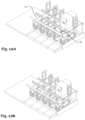
- FIG. 11A schematically illustrating an FDR comprising a plurality of stalls (10-14) and an MFU (20) movable along a front elevated rail system (31F) to feed a diary animal (1) when milked in its stall (10).
- a front rail system (FER, 30F)
- a rear elevated rail (RER) are provided in parallel, perpendicular to the stall lines.
- an autonomously actuated taxi module 42 is currently attached to an MMU (41) which is located above the rear portion of the stall (10).
- the MMU (41) introduces the cow (1) milking system to the rear portion of the cow within the stall (10), the MMU (41) or an interconnectable module, e.g., an autonomous movable taxi unit (42), is reversibly separable from the milking system and is ready for further tasks, e.g., to transfer other milking systems to other cows in neighboring stalls, to deliver a movable intermediate milk container (not shown here) to accept milk from other stalls in the line or unload the milk to a milk emptying facility along the line.
- an interconnectable module e.g., an autonomous movable taxi unit (42)
- the taxi that delivers a mobile unit in the exemplary case of Fig. 11A- B, an MMU, to a stall need not be the same as the taxi that transfers the mobile unit to another stall, and, similarly, a taxi that delivers a milking system to a cow need not be the taxi that collects the milking system from the cow and delivers it to another cow.
- the FER (30F) comprises here two parallel rails (31 and 32), and the RER (30R) comprises two parallel rails (33 and 34). It is well within the scope of invention where each of the elevated rail systems comprises, in at least a portion of the line, one rail, two rails, and even three, four or more rails. Some of the rails disclosed in the invention are configured to be concurrently used by FER, RER or both, see e.g., middle and mutual rail (32-33) having two sides: a front side (32) and rear side (33).
- the RER and the FER are provided in parallel, yet other arrangements are possible, for example, a standalone (namely only one type of rail) or in combination with other types of rail, including a mutual middle rail where an RER is provided on the rear side of one or more rails with an FER provided on the front side of those rails.
- an upper portion of the rail(s) serves mobile units of the front side (2) of the stalls and a lower portion of the rail(s) concurrently serves mobile units of the rear side (3) of same stalls, and vice versa.
- the MFU (20) comprises a top portion (21) adapted to accept either a metered-dose batch food portion or a continuous flow of the same, and, in some examples, to process it, e.g., by grinding or milling it to a smooth food serving, wetting it, admixing various feed ingredients, measure its quantity, etc.
- the food portion is then administered in front of the milked cow (1) e.g., by means of a hose (22).
- a cultivating unit, a food gathering unit, a measurement module such as a camera (thermal or optic), a sensor and any combination thereof can be affixed on, in, or in connection with the front hose (22).
- the front hose can direct the feed to a front eating zone (23).
- the hose member can be configured, according to various examples of the invention, still in a non-limiting manner, for being activated as a feed pusher, feed remixer, and feed compressor/spreader.
- FIG. 11B presenting the same, where an MFU (20) has been moved sideward (4) on an FER (30F) from one stall (10) to a second stall (12), e.g., to feed a neighboring cow.
- the MMU on the RER is independently movable; here its current location remains above the first stall (10), as the MMU is still robotically milking the first cow (1).
- an MTU is communicable with an MMU by means of a fluid connection tubing line.
- milk from the MMU flows via the tubing line.
- the connection between the two modules is ended and the MTU is free to move to other sites along an FER.
- the MTU has direct communication with an MMU.
- an MTU milk tubing line is indirectly connected to an MMU via a taxi. Can be connected for transferring the milk and disconnected thereafter.
- an MTU has a self-contained milk cooling system or otherwise is in connection with other cooling systems, e.g., a cooling system incorporated along an FER.
- An MTU can further comprise another supporting system, such as a heating capability (e.g., pasteurizing or decontaminating facilities), a milk-diagnosing and analyzing means, a container-cleansing system, etc. and any combination thereof.
- Fig. 12B presenting the same, where the MTU (50) is detached from a taxi/MMU, and has been moved from one stall (10) to another stall (12) along an FER (30F) in a direction (4), e.g., to be ready for inflow of new milk or to unload its milk into a terminal milk container (not shown).
- Dairy cows generate heat.
- a cow providing 54 kg of milk per day generates about 6646.8 KJ (6,300 BTU per hour) twice as much heat as a cow producing only 18 kg of milk per day (3481.6 KJ, i.e. 3,300 BTU/h) and 19 times the 348.17 KJ (330 BTU/h) a human produce at rest.
- cows are quite cold tolerant, they are heat stressed at a temperature that most humans find comfortable; their thermoneutral zone is in the range of about 4° C to about 21° C.
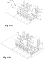
- Fig. 13A schematically illustrating an FDR comprising a plurality of stalls (10-14) and a mobile cooling unit (MCU, 60), movable along the front elevated rail system (31F) to cool the stall where the cow is milked during milking.
- Fig. 13B shows the same, except that the MCU (50) has been moved, either autonomously or by a taxi, to another stall after chilling the milked cow (1) in the first stall (10).
- the system will typically comprise fewer taxi units than MMUs, MCUs, MFUs, MTUs, MCCs, stall cleaning units, animal cleaning units and other units. However, in some embodiments, there are as many or more taxi units as MMUs, MCUs, MFUs, MTUs, MCCs, stall cleaning units, animal cleaning units and other units.
- a system can comprise any combination of MMUs, MCUs, MFUs, MTUs, MCCs, stall cleaning units, animal cleaning units and other units.
- a system can comprise mobile MMUs only, while another exemplary unit comprises only taxis and passive MMUs, with another comprising taxis, mobile MMUs, passive MMUs, as well as MFUs and MTUs.
- the integration of the modules (FER, RER, the mobile units, and the taxis, if present) with an intelligent and adaptive AI system to perform all operations (including feeding) before, during and after milking, can be configured to optimize the flow of cows into the system, both on the level of the treatment of an individual cow and on the level of the flow of cows through a cow stall area such as, for example, a milking parlor. All to achieve optimal visits of the cows to the stall and maximum utilized time of the cows staying in the stalls: for feeding and milking and maximum milking capacity of the system.
- the system is adaptive, being configured to learn, so that treatment of each cow can be adapted to the condition of the cow, if and when such condition changes.
- the system can prepare each cow that is supposed to be milked during its visit to a manger, while taking advantage of the order of appearance of the cows and the maximum time needed to prepare the cow for milking, milk her and provide after-milking care and treatment. In this way, the cow's convenience and her well-being can be maximized during her time in a milking stall (during feeding and milking), resulting in more milk, higher quality milk and greater cow health.
- a cow will want to enter a feeding/milking stall, where she will benefit from environmental conditions and services individually configurable for her comfort and convenience.
- one or more mobile milking units are mobilized along one or more RERs to milk cows, at time intervals correlated with the time when cows freely enter any of the stalls or standing within the stalls for feeding.
- one or more mobile feeding units are mobilized along one or more FERs towards these one or more stalls.
- same or other FER(s) are carrying one or more mobile feeding units, one or more mobile milk transfer units, one or more mobile cooling units and/or other mobile units with different services as listed above.
- one or more mobile feeding units are mobilized along FER to feed cows with an additional food, and thereby completing defined (e.g., personalized per cow) nutrition, in accordance with cows specific and condition-related feed scheme.
- defined e.g., personalized per cow
- Such a personalized feed mechanism synergistically shortening cows' preparation time, increasing the effectivity of attracting the cows to enter the stalls, and improved health of the entire herd by that each cow is milked upon its individual (personalized-) milking-interval.
- one or more mobile milking units are concurrently mobilized along FER for cooling cows in their stalls before and during milking.
- Such a personalized and accurately timed cooling in each of the stalls along time ensures a convenient and effective micro-climate in stall, and hence significantly increases both (a) yields of milking and (b) quality life of the cow.
- one or more mobile milk transfer units on one or more FERs are emptying one or more mobile milking units on one or more RERs at a timed procedure, namely immediately after cows are milked. Shortly after that, the mobile milk transfer units carry the milk, along the FERs, to one or more milk collecting points. Hence, the hereto emptied mobile milking units are allowed to continue milking other cows so that milking capacity of the farm increase.
- any given mobile service units running along FER in a timed manner provides a synergistic increase in both agrotechnical parameters (e.g., higher milk yield, better milk quality) and cow's wealth, when combined with the concurrent operation of other mobile service units running along RER.
- Another aspect of the invention is a dairy farm with an elevated road for free transport of mobile units and methods thereof.
- the milking module and/or sub-modules thereof actuate from the rear portion of the dairy animal (tail side, e.g., between the rear legs) towards the teats.
- the milking module and/or sub-modules thereof actuate from at least one side of the dairy animal (tail side, 6 o'clock, e.g., between the front and rear left/right legs) towards the teats.
- side of the dairy animal refers to a location being lateral to the dairy animal's main longitudinal axis, and includes one or more of the following: (i) rear-and-side (e.g., advancing angles being about 4 or about 8 o'clock, when the tail and head are about 6 and 12 o'clock, respectively); (ii) side, namely adjacent and to the side of the teats at a height lower than the teats, adjacent and to the side of the teats and about the height of the teats, adjacent and to the side of the teats and higher than the teats etc.; at about 3 and 9 o'clock; and side and front, namely at about 2 and about 10 o'clock.
- rear-and-side e.g., advancing angles being about 4 or about 8 o'clock, when the tail and head are about 6 and 12 o'clock, respectively
- side namely adjacent and to the side of the teats at a height lower than the teats, adjacent and to the side of the tea
- the milking module and/or sub-modules thereof actuate from a combination of at least one (lateral-) side of the dairy animal, from the rear side, front side, below, above and any combination and orientation thereof.
- the present invention relates to a milking station to be used for milking cows and the like, as is well known in the art.
- the present milking station may be used for milking various other types of animals.
- the present milking station is preferably of simple design and inexpensive to manufacture.
- the present milking station possesses several advantages when compared to conventional milking stations known in the art.
Landscapes
- Life Sciences & Earth Sciences (AREA)
- Environmental Sciences (AREA)
- Animal Husbandry (AREA)
- Biodiversity & Conservation Biology (AREA)
- Zoology (AREA)
- Birds (AREA)
- Feeding And Watering For Cattle Raising And Animal Husbandry (AREA)
- Housing For Livestock And Birds (AREA)
Claims (9)
- Milchviehbetrieb, der Folgendes umfasst: (a) eine Reihe von n auf einer Milchviehebene nebeneinanderliegenden Ständen (n-1, n, n+1, n+2), wobei jeder der Stände anhand seiner Größe und Form so konfiguriert ist, dass er ein Milchvieh (1) aufnehmen kann, und eine Hauptlängsachse Y aufweist, wobei entlang der Y-Achse eine Vorderseite dem Kopf (1h) des Tiers und eine gegenüberliegende Rückseite dem Schwanz (1t) des Tiers zugewandt ist, (b) eine auf einer höheren Ebene über den Ständen vorgesehene, gemeinsam genutzte, erhöhte Straßenfläche (2), wobei sich die Straßenfläche eine Achse X entlang erstreckt, die im Wesentlichen senkrecht zur Achse Y verläuft, und (c) mindestens eine mobile Einheit, die mindestens eine mobile Melkeinheit (MMU, 10) aufweist und so konfiguriert ist, dass sie sich auf der erhöhten Straßenfläche (2) entlang der X-Achse, entlang der Y-Achse, um die X-Achse herum, um die Y-Achse herum und um die Z-Achse herum frei bewegt oder bewegen lässt.
- Milchviehbetrieb nach Anspruch 1, wobei die Straßenfläche (2) eine oder mehrere Öffnungen (3n) umfasst, die entlang der vertikalen Z-Achse eine freie Verbindung zwischen einer Oberfläche der Straßenfläche und dem darunterliegenden Stand ermöglichen.
- Milchviehbetrieb nach Anspruch 2, wobei jeder der n Stände (z.B. n-1, n, n+1, n+2) an seinem hinteren Teil eine Öffnung 3(n-1), 3(n), 3(n+1) beziehungsweise 3(n+2) umfasst.
- Milchviehbetrieb nach Anspruch 3, wobei sich der hintere Teil in einem Bereich befindet, der aus einer Gruppe ausgewählt ist, die aus Folgendem besteht: hinter den Zitzen (1t) des Milchviehs, neben den Zitzen (1t) des Milchviehs, vor den Zitzen (1t) des Milchviehs und einer beliebigen Kombination davon.
- Milchviehbetrieb nach Anspruch 1, wobei die Mobileinheit-Andockstation (6) neben mindestens einer der Öffnungen vorgesehen ist, wobei die Andockstation Mittel zum Bedienen der mindestens einen MMU umfasst, wobei die Bedienung aus einer Gruppe ausgewählt wird, die aus dem Bereitstellen von Energie, dem Bereitstellen von Dampf, dem Bereitstellen von mindestens einem Fluid, dem Entnehmen von mindestens einem Fluid und dem Entnehmen von Milch besteht.
- Milchviehbetrieb nach Anspruch 2, wobei sich neben jeder der Öffnungen mindestens ein vertikaler Transportmechanismus (VTM, 4a-c) befindet.
- Milchviehbetrieb nach Anspruch 1, wobei die MMU ein Melkmodul umfasst, damit verbunden ist oder in Verbindung steht, das so konfiguriert ist, dass es sich in einer Bewegung zu den Zitzen des Milchviehs hin bewegt, die auf eine Weise erfolgt, welche aus einer Gruppe ausgewählt ist, die (a) im Verlauf zumindest eines Teils der Gesamtbewegung aus dem Bewegen unterhalb des Milchviehs, in Zitzenhöhe, in einer etwa in der Mitte des Milchviehs liegenden Höhe, oberhalb des Milchviehs und einer beliebigen Kombination davon, (b) im Verlauf zumindest eines Teils der Gesamtbewegung aus dem Bewegen in einer Richtung besteht, die aus einer Gruppe ausgewählt ist, welche aus zum Milchvieh hin, vom Milchvieh weg, am Milchvieh entlang, am hinteren Teil des Milchviehs, am seitlichen Teil des Milchviehs, am vorderen Teil des Milchviehs und einer beliebigen Kombination und Ausrichtung davon besteht.
- Milchviehbetrieb nach Anspruch 1, wobei die mindestens eine Mobileinheit ferner ein Element umfasst, das aus einer Gruppe ausgewählt ist, welche aus einem Taxi, einer mobilen Füttereinheit (MFU), einer mobilen Kühleinheit (MCU), einer mobilen Milchtransfereinheit (MTU), einer Standreinigungseinheit, einer Tierreinigungseinheit, einer Tiermesseinheit, einer Tieridentifiziereinheit, einer ohrmarkenunabhängigen Identifizierungseinheit, einer Tiergesundheitsbewertungseinheit, einer Tierdokumentationseinheit, einer Tier/Stand-Zuordnungseinheit, einer Tier/Melkgruppe-Zuordnungseinheit, einer Tierfutteranalyseeinheit, einer Kuhgesundheitseinheit, einer Futteraufnahmeeinheit, einer Östrusdiagnoseeinheit, einer Warneinheit, einer Futtervorschubeinheit, einer Futterneumischeinheit, einer Futterkompressionseinheit, einer Futterverdichtungseinheit, einer Auffrisch- oder Streueinheit, einer automatischen Futterladeeinheit, einer Futterzubereitungseinheit und einer beliebigen Kombination davon besteht.
- Milchviehbetrieb nach Anspruch 1, wobei der Milchviehbetrieb eine Steuerung mit künstlicher Intelligenz (KI) umfasst, wobei die Steuerung so konfiguriert ist, dass sie eine Bewegung jeder der mindestens einen mobilen Einheit steuert, wobei die Steuerung so konfiguriert ist, dass sie die mindestens eine mobile Einheit an mindestens einem vorgegebenen Standort positioniert und die Bewegung der mindestens einen mobilen Einheit entweder unabhängig von einem damit zusammenhängenden System von Operationen oder als Bestandteil davon steuert.
Priority Applications (1)
| Application Number | Priority Date | Filing Date | Title |
|---|---|---|---|
| EP23191692.5A EP4298899A1 (de) | 2019-08-28 | 2020-08-27 | Milchviehbetrieb mit einer einzigen oder mehreren vorderen erhöhten strassen |
Applications Claiming Priority (4)
| Application Number | Priority Date | Filing Date | Title |
|---|---|---|---|
| IL268978A IL268978B (en) | 2019-08-28 | 2019-08-28 | A dairy farm with a front elevated rail system |
| IL271314A IL271314B (en) | 2019-12-10 | 2019-12-10 | A dairy farm with an elevated road for free transport of mobile units and methods thereof |
| IL274851A IL274851B (en) | 2020-05-21 | 2020-05-21 | In a stall, a gate for limiting the access of a dairy animal to its feed and method thereof |
| PCT/IL2020/050934 WO2021038566A1 (en) | 2019-08-28 | 2020-08-27 | A dairy farm with a single or multiple frontal elevated roads |
Related Child Applications (2)
| Application Number | Title | Priority Date | Filing Date |
|---|---|---|---|
| EP23191692.5A Division-Into EP4298899A1 (de) | 2019-08-28 | 2020-08-27 | Milchviehbetrieb mit einer einzigen oder mehreren vorderen erhöhten strassen |
| EP23191692.5A Division EP4298899A1 (de) | 2019-08-28 | 2020-08-27 | Milchviehbetrieb mit einer einzigen oder mehreren vorderen erhöhten strassen |
Publications (4)
| Publication Number | Publication Date |
|---|---|
| EP4021170A1 EP4021170A1 (de) | 2022-07-06 |
| EP4021170A4 EP4021170A4 (de) | 2022-11-30 |
| EP4021170B1 true EP4021170B1 (de) | 2025-05-07 |
| EP4021170C0 EP4021170C0 (de) | 2025-05-07 |
Family
ID=74684968
Family Applications (2)
| Application Number | Title | Priority Date | Filing Date |
|---|---|---|---|
| EP23191692.5A Pending EP4298899A1 (de) | 2019-08-28 | 2020-08-27 | Milchviehbetrieb mit einer einzigen oder mehreren vorderen erhöhten strassen |
| EP20857377.4A Active EP4021170B1 (de) | 2019-08-28 | 2020-08-27 | Milchviehbetrieb mit einer einzigen oder mehreren vorderen erhöhten strassen |
Family Applications Before (1)
| Application Number | Title | Priority Date | Filing Date |
|---|---|---|---|
| EP23191692.5A Pending EP4298899A1 (de) | 2019-08-28 | 2020-08-27 | Milchviehbetrieb mit einer einzigen oder mehreren vorderen erhöhten strassen |
Country Status (7)
| Country | Link |
|---|---|
| US (1) | US11528884B2 (de) |
| EP (2) | EP4298899A1 (de) |
| CN (1) | CN114667061A (de) |
| AU (1) | AU2020335393B2 (de) |
| CA (2) | CA3150963C (de) |
| DE (1) | DE202020005554U1 (de) |
| WO (1) | WO2021038566A1 (de) |
Families Citing this family (1)
| Publication number | Priority date | Publication date | Assignee | Title |
|---|---|---|---|---|
| DE102021131077A1 (de) * | 2021-11-26 | 2023-06-01 | Gea Farm Technologies Gmbh | Fahrroboter für landwirtschaftliche Aufgaben |
Citations (1)
| Publication number | Priority date | Publication date | Assignee | Title |
|---|---|---|---|---|
| EP0332232A2 (de) * | 1985-01-16 | 1989-09-13 | C. van der Lely N.V. | Gerät zum Melken von Tieren, z.B. Kühen |
Family Cites Families (39)
| Publication number | Priority date | Publication date | Assignee | Title |
|---|---|---|---|---|
| US1009714A (en) | 1911-07-12 | 1911-11-28 | Matthew S Batchelder | Cow-stall. |
| GB665753A (en) | 1949-03-15 | 1952-01-30 | Gascoignes Reading Ltd | Improvements in milking machines |
| US2601845A (en) | 1949-03-25 | 1952-07-01 | John D Youngman | Stall with retaining gate |
| US3166044A (en) | 1963-03-28 | 1965-01-19 | Norman E Darling | Device for releasing cows |
| US3167053A (en) | 1963-07-08 | 1965-01-26 | John E Mcdaniel | Animal holding pen |
| US4034711A (en) | 1975-07-31 | 1977-07-12 | Bender Machine Works, Inc. | Mobile milk unit and system |
| US4047500A (en) | 1976-09-23 | 1977-09-13 | Bender Machine Works, Inc. | Milking apparatus and method for operating same |
| US4171684A (en) | 1977-03-18 | 1979-10-23 | The De Laval Separator Company | Stall design of feeding station |
| DE2818621A1 (de) * | 1978-04-27 | 1979-10-31 | Herbert Osthoff | Melkanlage |
| NL9002465A (nl) * | 1990-11-12 | 1992-06-01 | Nedap Nv | Voersysteem voor dieren. |
| DE4204475A1 (de) * | 1992-02-14 | 1993-08-19 | Franz Schindele | Verfahren und vorrichtung zum fuettern von tieren |
| DE69333988T2 (de) | 1992-11-02 | 2006-11-09 | Maasland N.V. | Vorrichtung zum Melken von Tieren |
| DE9305052U1 (de) | 1993-04-02 | 1993-06-03 | Hänel, Adolf, Dipl.-Ing., O-7904 Elsterwerda | Fahrbare Kannenmelkanlage |
| NL9301260A (nl) * | 1993-07-19 | 1995-02-16 | Texas Industries Inc | Inrichting voor het automatisch melken van dieren. |
| NL1001336C1 (nl) | 1995-02-24 | 1996-08-28 | Maasland Nv | Constructie met een inrichting voor het melken van dieren. |
| DK1084611T3 (da) * | 1996-07-05 | 2005-01-31 | Maasland Nv | Malkemaskine til automatisk malkning af dyr |
| JPH10229766A (ja) * | 1997-02-18 | 1998-09-02 | Seibutsukei Tokutei Sangyo Gijutsu Kenkyu Suishin Kiko | 自動搾乳機 |
| EP1078570A1 (de) * | 1999-08-20 | 2001-02-28 | N.V. Nederlandsche Apparatenfabriek NEDAP | Liegeverhinderungsvorrichtung für Tiere |
| NL1015671C2 (nl) | 2000-07-10 | 2002-01-11 | Lely Entpr Ag | Inrichting voor het automatisch melken van dieren. |
| RU2226822C2 (ru) | 2001-06-26 | 2004-04-20 | Институт Животноводства Украинской Академии Аграрных Наук | Передвижной доильный агрегат |
| RU2233079C2 (ru) | 2001-08-20 | 2004-07-27 | Азово-Черноморская государственная агроинженерная академия | Передвижная доильная установка |
| NL1020004C2 (nl) | 2002-02-19 | 2003-08-21 | Lely Entpr Ag | Samenstel voor het voederen en melken van dieren, en werkwijze voor het voederen en voor het melken van dieren. |
| NL1024518C2 (nl) * | 2003-10-13 | 2005-04-14 | Lely Entpr Ag | Samenstel en werkwijze voor het voederen en melken van dieren, voederplatform, melksysteem, voedersysteem, melkvoorbehandelingsinrichting, melknabehandelingsinrichting, reinigingsinrichting en separatie-inrichting, alle geschikt voor gebruik in een dergelijk samenstel. |
| NL1031575C2 (nl) * | 2006-04-12 | 2007-10-15 | Maasland Nv | Werkwijze en inrichting voor het voeren van een dier in een voerbox. |
| ITMI20061483A1 (it) | 2006-07-27 | 2008-01-28 | Interpuls Spa | Dispositivo per connettere un'unita' mobile di mungitura con il lattodotto,il tubo del latte e l'alimentazione elettrica |
| NL1032435C2 (nl) | 2006-09-05 | 2008-03-06 | Maasland Nv | Inrichting voor het automatisch melken van een melkdier. |
| NL2005889C2 (nl) * | 2010-12-21 | 2012-06-25 | Stichting Administratiekantoor Weelink Berendsen | Meng- en doseerinrichting voor veevoeder. |
| RU2466533C1 (ru) | 2011-04-05 | 2012-11-20 | Государственное научное учреждение Всероссийский научно-исследовательский институт механизации животноводства Российской академии сельскохозяйственных наук (ГНУ ВНИИМЖ Россельхозакадемии) | Передвижной доильный агрегат |
| US9215861B2 (en) * | 2011-04-28 | 2015-12-22 | Technologies Holdings Corp. | Milking box with robotic attacher and backplane for tracking movements of a dairy animal |
| US9675043B2 (en) * | 2011-12-16 | 2017-06-13 | Delaval Holding Ab | Rotary parlour arranged to house animals to be milked |
| CN203226118U (zh) | 2013-04-28 | 2013-10-09 | 上海永济牧业设备有限公司 | 带有改进的集乳器的移动式挤奶器 |
| RU2538384C1 (ru) | 2013-08-01 | 2015-01-10 | Государственное научное учреждение Всероссийский научно-исследовательский институт механизации животноводства Российской академии сельскохозяйственных наук, ГНУ ВНИИМЖ Россельхозакадемии | Передвижной доильный агрегат |
| WO2017051418A2 (en) | 2015-09-21 | 2017-03-30 | Afimilk Agricultural Cooperative Ltd. | Mobile milking robot with minimal footprint configured to operate in a parallel milking parlor |
| CA3020245C (en) * | 2016-04-01 | 2025-02-04 | Delaval Holding Ab | MILKING MODULE, MILKING ARRANGEMENT, AND GROUP MILKING METHOD |
| IL246617B2 (en) * | 2016-07-05 | 2023-10-01 | Eyal Brayer | Means and Methods for Free Dome Range |
| CR20210128A (es) | 2017-01-27 | 2021-04-26 | Immatics Biotechnologies Gmbh | Nuevos péptidos y nuevas combinaciones de péptidos para el uso en la inmunoterapia contra el cáncer de ovario y otros tipos de cancer (divisional exp. 2019-388) |
| DE202017007021U1 (de) * | 2017-07-05 | 2019-05-24 | Dairyionics Ltd. | Mittel für eine überwölbte Freilandhaltung |
| US10796142B2 (en) * | 2017-08-28 | 2020-10-06 | Nutech Ventures | Systems for tracking individual animals in a group-housed environment |
| IL271314B (en) | 2019-12-10 | 2021-07-29 | Dairyionics Ltd | A dairy farm with an elevated road for free transport of mobile units and methods thereof |
-
2020
- 2020-08-27 EP EP23191692.5A patent/EP4298899A1/de active Pending
- 2020-08-27 US US17/635,107 patent/US11528884B2/en active Active
- 2020-08-27 CA CA3150963A patent/CA3150963C/en active Active
- 2020-08-27 CA CA3185784A patent/CA3185784A1/en active Pending
- 2020-08-27 DE DE202020005554.9U patent/DE202020005554U1/de active Active
- 2020-08-27 AU AU2020335393A patent/AU2020335393B2/en active Active
- 2020-08-27 WO PCT/IL2020/050934 patent/WO2021038566A1/en not_active Ceased
- 2020-08-27 CN CN202080073461.5A patent/CN114667061A/zh active Pending
- 2020-08-27 EP EP20857377.4A patent/EP4021170B1/de active Active
Patent Citations (1)
| Publication number | Priority date | Publication date | Assignee | Title |
|---|---|---|---|---|
| EP0332232A2 (de) * | 1985-01-16 | 1989-09-13 | C. van der Lely N.V. | Gerät zum Melken von Tieren, z.B. Kühen |
Also Published As
| Publication number | Publication date |
|---|---|
| AU2020335393B2 (en) | 2023-04-06 |
| CA3150963A1 (en) | 2021-03-04 |
| EP4298899A1 (de) | 2024-01-03 |
| US11528884B2 (en) | 2022-12-20 |
| CN114667061A (zh) | 2022-06-24 |
| EP4021170A4 (de) | 2022-11-30 |
| CA3185784A1 (en) | 2021-03-04 |
| EP4021170A1 (de) | 2022-07-06 |
| CA3150963C (en) | 2023-01-03 |
| WO2021038566A1 (en) | 2021-03-04 |
| US20220264841A1 (en) | 2022-08-25 |
| DE202020005554U1 (de) | 2022-02-03 |
| EP4021170C0 (de) | 2025-05-07 |
| AU2020335393A1 (en) | 2022-03-24 |
Similar Documents
| Publication | Publication Date | Title |
|---|---|---|
| DE602004004969T2 (de) | Verfahren zum Melken eines Tieres | |
| CN109788739B (zh) | 用于散养家畜牧场的装置和方法 | |
| De Koning et al. | Automatic milking experience and development in Europe | |
| EP4021170B1 (de) | Milchviehbetrieb mit einer einzigen oder mehreren vorderen erhöhten strassen | |
| Oberschätzl-Kopp et al. | Studies on dairy cow behaviour with automatic feeding in a herd milked by an AMS | |
| US10813340B2 (en) | System and method for milking a group of milking animals | |
| US8281742B2 (en) | System for milking cows and method | |
| CA2994686C (en) | System and method for milking a group of milking animals | |
| CA2996262C (en) | System for milking a group of dairy animals | |
| US11439121B2 (en) | System and method for milking a group of milking animals | |
| Morita et al. | Eating and resting behavior of cows in bedded pack type loose housing with an automatic milking system |
Legal Events
| Date | Code | Title | Description |
|---|---|---|---|
| STAA | Information on the status of an ep patent application or granted ep patent |
Free format text: STATUS: THE INTERNATIONAL PUBLICATION HAS BEEN MADE |
|
| PUAI | Public reference made under article 153(3) epc to a published international application that has entered the european phase |
Free format text: ORIGINAL CODE: 0009012 |
|
| STAA | Information on the status of an ep patent application or granted ep patent |
Free format text: STATUS: REQUEST FOR EXAMINATION WAS MADE |
|
| 17P | Request for examination filed |
Effective date: 20220325 |
|
| AK | Designated contracting states |
Kind code of ref document: A1 Designated state(s): AL AT BE BG CH CY CZ DE DK EE ES FI FR GB GR HR HU IE IS IT LI LT LU LV MC MK MT NL NO PL PT RO RS SE SI SK SM TR |
|
| A4 | Supplementary search report drawn up and despatched |
Effective date: 20221028 |
|
| RIC1 | Information provided on ipc code assigned before grant |
Ipc: A01K 5/02 20060101ALI20221024BHEP Ipc: A01K 1/00 20060101ALI20221024BHEP Ipc: A01J 9/00 20060101ALI20221024BHEP Ipc: A01J 7/02 20060101ALI20221024BHEP Ipc: A01J 5/017 20060101ALI20221024BHEP Ipc: A01J 5/013 20060101ALI20221024BHEP Ipc: A01J 5/01 20060101ALI20221024BHEP Ipc: A01J 5/003 20060101ALI20221024BHEP Ipc: A01K 1/12 20060101AFI20221024BHEP |
|
| DAV | Request for validation of the european patent (deleted) | ||
| DAX | Request for extension of the european patent (deleted) | ||
| STAA | Information on the status of an ep patent application or granted ep patent |
Free format text: STATUS: EXAMINATION IS IN PROGRESS |
|
| 17Q | First examination report despatched |
Effective date: 20231108 |
|
| GRAP | Despatch of communication of intention to grant a patent |
Free format text: ORIGINAL CODE: EPIDOSNIGR1 |
|
| STAA | Information on the status of an ep patent application or granted ep patent |
Free format text: STATUS: GRANT OF PATENT IS INTENDED |
|
| INTG | Intention to grant announced |
Effective date: 20241114 |
|
| GRAS | Grant fee paid |
Free format text: ORIGINAL CODE: EPIDOSNIGR3 |
|
| GRAA | (expected) grant |
Free format text: ORIGINAL CODE: 0009210 |
|
| STAA | Information on the status of an ep patent application or granted ep patent |
Free format text: STATUS: THE PATENT HAS BEEN GRANTED |
|
| AK | Designated contracting states |
Kind code of ref document: B1 Designated state(s): AL AT BE BG CH CY CZ DE DK EE ES FI FR GB GR HR HU IE IS IT LI LT LU LV MC MK MT NL NO PL PT RO RS SE SI SK SM TR |
|
| REG | Reference to a national code |
Ref country code: GB Ref legal event code: FG4D |
|
| REG | Reference to a national code |
Ref country code: CH Ref legal event code: EP |
|
| REG | Reference to a national code |
Ref country code: DE Ref legal event code: R096 Ref document number: 602020051035 Country of ref document: DE |
|
| REG | Reference to a national code |
Ref country code: IE Ref legal event code: FG4D |
|
| U01 | Request for unitary effect filed |
Effective date: 20250609 |
|
| U07 | Unitary effect registered |
Designated state(s): AT BE BG DE DK EE FI FR IT LT LU LV MT NL PT RO SE SI Effective date: 20250708 |
|
| U20 | Renewal fee for the european patent with unitary effect paid |
Year of fee payment: 6 Effective date: 20250723 |
|
| PG25 | Lapsed in a contracting state [announced via postgrant information from national office to epo] |
Ref country code: ES Free format text: LAPSE BECAUSE OF FAILURE TO SUBMIT A TRANSLATION OF THE DESCRIPTION OR TO PAY THE FEE WITHIN THE PRESCRIBED TIME-LIMIT Effective date: 20250507 |
|
| PG25 | Lapsed in a contracting state [announced via postgrant information from national office to epo] |
Ref country code: NO Free format text: LAPSE BECAUSE OF FAILURE TO SUBMIT A TRANSLATION OF THE DESCRIPTION OR TO PAY THE FEE WITHIN THE PRESCRIBED TIME-LIMIT Effective date: 20250807 Ref country code: GR Free format text: LAPSE BECAUSE OF FAILURE TO SUBMIT A TRANSLATION OF THE DESCRIPTION OR TO PAY THE FEE WITHIN THE PRESCRIBED TIME-LIMIT Effective date: 20250808 |
|
| PG25 | Lapsed in a contracting state [announced via postgrant information from national office to epo] |
Ref country code: PL Free format text: LAPSE BECAUSE OF FAILURE TO SUBMIT A TRANSLATION OF THE DESCRIPTION OR TO PAY THE FEE WITHIN THE PRESCRIBED TIME-LIMIT Effective date: 20250507 |
|
| PGFP | Annual fee paid to national office [announced via postgrant information from national office to epo] |
Ref country code: GB Payment date: 20250723 Year of fee payment: 6 |
|
| PG25 | Lapsed in a contracting state [announced via postgrant information from national office to epo] |
Ref country code: HR Free format text: LAPSE BECAUSE OF FAILURE TO SUBMIT A TRANSLATION OF THE DESCRIPTION OR TO PAY THE FEE WITHIN THE PRESCRIBED TIME-LIMIT Effective date: 20250507 |
|
| PG25 | Lapsed in a contracting state [announced via postgrant information from national office to epo] |
Ref country code: RS Free format text: LAPSE BECAUSE OF FAILURE TO SUBMIT A TRANSLATION OF THE DESCRIPTION OR TO PAY THE FEE WITHIN THE PRESCRIBED TIME-LIMIT Effective date: 20250807 |
|
| PG25 | Lapsed in a contracting state [announced via postgrant information from national office to epo] |
Ref country code: IS Free format text: LAPSE BECAUSE OF FAILURE TO SUBMIT A TRANSLATION OF THE DESCRIPTION OR TO PAY THE FEE WITHIN THE PRESCRIBED TIME-LIMIT Effective date: 20250907 |