EP4018027B1 - Vorrichtung zum sammeln von geschnittenen schussfäden für webmaschinen - Google Patents
Vorrichtung zum sammeln von geschnittenen schussfäden für webmaschinen Download PDFInfo
- Publication number
- EP4018027B1 EP4018027B1 EP20767605.7A EP20767605A EP4018027B1 EP 4018027 B1 EP4018027 B1 EP 4018027B1 EP 20767605 A EP20767605 A EP 20767605A EP 4018027 B1 EP4018027 B1 EP 4018027B1
- Authority
- EP
- European Patent Office
- Prior art keywords
- fabric
- weft
- shuttle
- tails
- shear
- Prior art date
- Legal status (The legal status is an assumption and is not a legal conclusion. Google has not performed a legal analysis and makes no representation as to the accuracy of the status listed.)
- Active
Links
Images


Classifications
-
- D—TEXTILES; PAPER
- D03—WEAVING
- D03D—WOVEN FABRICS; METHODS OF WEAVING; LOOMS
- D03D45/00—Looms with automatic weft replenishment
- D03D45/50—Cutting, holding, manipulating, or disposing of, weft ends
-
- D—TEXTILES; PAPER
- D03—WEAVING
- D03D—WOVEN FABRICS; METHODS OF WEAVING; LOOMS
- D03D47/00—Looms in which bulk supply of weft does not pass through shed, e.g. shuttleless looms, gripper shuttle looms, dummy shuttle looms
- D03D47/12—Looms in which bulk supply of weft does not pass through shed, e.g. shuttleless looms, gripper shuttle looms, dummy shuttle looms wherein single picks of weft thread are inserted, i.e. with shedding between each pick
- D03D47/125—Weft holding devices
-
- D—TEXTILES; PAPER
- D03—WEAVING
- D03D—WOVEN FABRICS; METHODS OF WEAVING; LOOMS
- D03D47/00—Looms in which bulk supply of weft does not pass through shed, e.g. shuttleless looms, gripper shuttle looms, dummy shuttle looms
- D03D47/34—Handling the weft between bulk storage and weft-inserting means
- D03D47/36—Measuring and cutting the weft
-
- D—TEXTILES; PAPER
- D03—WEAVING
- D03D—WOVEN FABRICS; METHODS OF WEAVING; LOOMS
- D03D47/00—Looms in which bulk supply of weft does not pass through shed, e.g. shuttleless looms, gripper shuttle looms, dummy shuttle looms
- D03D47/34—Handling the weft between bulk storage and weft-inserting means
- D03D47/38—Weft pattern mechanisms
-
- D—TEXTILES; PAPER
- D03—WEAVING
- D03D—WOVEN FABRICS; METHODS OF WEAVING; LOOMS
- D03D49/00—Details or constructional features not specially adapted for looms of a particular type
- D03D49/70—Devices for cutting weft threads
Definitions
- the present invention relates to a shuttle-less weaving machine comprising a fabric weft saving device; the aforesaid device allows to eliminate split selvages through specific controls and interventions on the side edges of the fabric.
- the present invention is placed in the field of devices adapted to the production of fabrics with shuttle-less weaving machines or looms, in particular rapier machines.
- the weaving machine technology can be divided into shuttle looms and shuttle-less weaving machines.
- the binding generally used for the selvages of shuttle-less looms is of the two-thread leno type, which is universally combined with the use of split selvages, which subsequently cut and eliminated, with the respective discarding of yarn.
- split selvages continue to be used because they ensure uniformity of the weft/warp interlacing structure between the center and sides of the fabric.
- the problem underlying the present invention is that of optimizing the weaving process in a shuttle-less loom, eliminating the split selvages which for various and different reasons described above increase the waste of yarn, but continue to ensure optimal finishing of the fabric.
- the known solutions were mainly aimed at the problems of the weft entry side into the warp.
- the entry side is characterized by the presence of a color selector for the presentation of the wefts coming from the reels to the rapiers, which lead to a vertex located at the beginning of the fabric formation line.
- sets of rapiers have generally been studied, in number equal to the number of wefts at work, each of which is responsible for managing the assigned thread, to withhold it, present it for insertion into the warp and then pick it back up at the end of the insertion cycle.
- the problems mainly concern the tension that the weft must maintain after the comb beat to ensure the stabilization of a uniform weft/weft interlacing between the center and sides of the fabric and to avoid random weft tails re-entering the fabric.
- the present device is based on the control of the weft thread tension at the ends of the fabric edges and the control of the arrangement of the weft portions protruding from the fabric.
- the aforesaid device prepares the weft tails for cutting with the use of mechanical and pneumatic elements and with specific side bindings which are more effective than the aforesaid leno bindings, and characterized by simple and intuitive management, which is part of the weaver's usual know-how.
- the first element of this process is a weft cut at the entry into the warp with three-dimensional adjustment of the cutting position, to optimize the length of the wefts protruding from the fabric.
- the side bindings of the edges of the fabric can be made with four threads crossing with each other or, alternatively, when allowed by the fabric, with two helical interlaced threads and variable timing of the pitch crossing with respect to the warp.
- the present invention relates to a device for shuttle-less weaving machines which allows weft saving with the elimination of split selvages, through the use and coordination of the component elements, indicated above, related to a weft cut such as to optimize the portions protruding from the fabric and a specific side binding of the edges of the fabric.
- On the sides of the fabric there are devices which are arranged at the exit from the temple to ensure the preparation of the wefts, on a guiding path which consists of a fixed plane which continues, in the final part, on a fixed blade parallel to the path of the fabric consisting of the blade of a shear.
- the aforesaid shear cuts the weft tails which are sucked by a nozzle and then recovered.
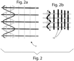
- the device ensures regularity of the weft/warp interlacing and uniformity between the center and selvages of the fabric similar to what would be obtained with split selvages. This is also achieved by bindings at the ends of the fabric made using dedicated warp threads and specific interlacing as shown in the figures below, to form a stable edge of the finished fabric.
- the weft saving device for weaving machines of the present invention is a structure placed between a comb 2 and a temple 3 for the formation of the fabric, placed on one side, and a fabric winding cylinder 8, placed on the other side, downstream from the comb 2 and temple 3.
- the edge of the fabric slides on a fixed guiding plane 6 placed at the exit of the temple 3 in the direction of the cylinder 8 and on a subsequent guiding section consisting of the lower blade 4, in a fixed position parallel to the fabric, of a shear 17.
- the second movable blade 5, e.g. of the oscillating type, of the shear 17 cuts the weft protrusions to the desired length.
- the suction system is in position under the blades 4 and 5 and is connected to the fixed guiding table 6 and the fixed blade 4 of the shear 17.
- FIG. 1 shows the edge of fabric 1 with specific warp and weft interlacing after each beat of the comb 2.
- Figure 2a shows the interlacing 9 with four crossed threads which the side binding of the inserted wefts ensures the necessary tension for the regularity of the weft/weft interlacing between the center and the sides of the fabric; such interlacing 9 may be provided with the use of the device according to the invention and allows to eliminate the draw of the split selvages. Alternatively, if allowed by the fabric, a similar function may be provided by a two-thread helical interlacing 10, as shown in figure 2b .
- the cutting method of the weft tails is illustrated in figures from 3 to 6 in alternative versions, e.g. such as mechanical, pneumatic, and/or mixed versions.
- Figure 3 shows a first embodiment of the present invention with a solution for controlling the weft tails comprising two opposing strips 11, 12, e.g. metallic and elastic, which are placed in contact on both sides of the fabric 1 and with the front part P near the temple 3.
- a solution for controlling the weft tails comprising two opposing strips 11, 12, e.g. metallic and elastic, which are placed in contact on both sides of the fabric 1 and with the front part P near the temple 3.
- the distance between the strips 11, 12 increases progressively along the cutting direction of the shear 17 and the profile of the aforesaid strips 11, 12, between which the edge of fabric 1 slides, pushes the weft tails outwards, which are first grouped towards a guiding edge MG, while the fabric 1 slides towards the cylinder 8.
- the weft tails are sucked by the suction system 7 and brought close to the guiding plane 6 under and the fixed blade 4 until they are cut by the movable blade 5 of the shear 17.
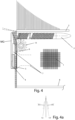
- Figure 4 shows a further embodiment of the invention, in which the device comprises a very thin and flexible metal disk 13, which is carved in a radial pattern, placed in contact with fabric 1 on an arc of its contour; the disk 13 is set in rotation by the feeding of the fabric 1 and by the radial shape and inclination ⁇ of its rotation axis ( figure 4a ).
- the metal disk 13 is elastically opposed to a second disk 13', under the fabric 1 with a specular arrangement to that of the disk above.
- the two disks 13, 13' by rotating pushed by the feeding of the fabric 1, arrange the weft tails which slide on the guiding table 6 and on the fixed blade 4 of the shear 17 as a fringe towards the outside of the fabric edge, in a position under the fabric 1, to be prepared for the cutting of the shear 17.
- Figure 5 shows a further embodiment of the device according to the present invention, comprising a suction nozzle 15 with flaps wound and overlapped as indicated in section A-A in figure 5a , with the edge of the fabric 1 which slides longitudinally in contact between the upper flap 14a and the lower flap 14b, while the compartment underneath has the function of sucking the weft tails for cutting with the shear 17 and preparing them on the guiding plane 6 and the fixed blade 4.
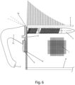
- Figure 6 shows another embodiment of the device according to the invention, wherein a suction nozzle 15 is used suitably arranged to keep the weft tails parallel to each other and in a position perpendicular to the edge of the fabric 1 until the exit from temple 3; the functional criteria are the same as described in the previous cases.
- the tails released by an exit rapier are recovered, with a part of the suction nozzle 15, which, placed beyond the temple 3 and with a suitable shape, forms the continuous guiding plane 6 with the fixed blade 4 of the shear 17; the movable blade 5 of the shear 17 then cuts the weft tails sucked by the nozzle 15.
- the suction nozzle 15 can have an airflow direction close to the weft direction.
- the weft tails advance with the fabric keeps the air direction trim until cutting and suction.
- the device in figure 6 also makes advantageous use of an elastic gripping element 16 on the guiding plane 6 of the weft tails advancing with the fabric 1.
- the gripping element 16 can be used when an additional thread tension is required before cutting with the shear 17.
Landscapes
- Engineering & Computer Science (AREA)
- Textile Engineering (AREA)
- Looms (AREA)
Claims (11)
- Schützenlose Webmaschine, welche dazu geeignet ist, einen Stoff (1) herzustellen, umfassend eine Stoffschuss-Speichervorrichtung, wobei die Vorrichtung zwischen einem Stoffbildebereich (1) angeordnet und betrieben ist, welche einen Kamm (2), welcher dazu eingerichtet ist, die Schussenden des Stoffs (1) zu schlagen, und einen Breithalter (3) umfasst, welcher dazu eingerichtet ist, den Stoff (1) transversal zu strecken, wobei der Kamm (2) und der Breithalter (3) auf einer entgegengesetzten Seite mit Bezug auf einen Zylinder (8) positioniert sind, welcher dazu eingerichtet ist, den Stoff (1) zu wickeln, wobei die Stoffschuss-Speichervorrichtung eine Führungsebene (6) für ein Führen des Stoffs (1), welche stromabwärts des Kamms (2) und des Breithalters (3) angeordnet ist, und eine Schere (17) umfasst, welche ein fixiertes Messer (4), welches unter dem Stoff (1) und stromabwärts der Führungsebene (6) angeordnet ist, und ein bewegliches Messer (5) aufweist, welches mit dem fixierten Messer (4) kooperiert, wobei die Stoffschuss-Speichervorrichtung ebenso umfasst:- eine pneumatisch und/oder mechanische Vorrichtung, welche für ein Gleiten der Schussenden des Stoffs (1) auf die Führungsebene (6) und zu dem fixierten Messer (4) und dem beweglichen Messer (6) der Schere (17) konfiguriert ist, wodurch die Schussenden des Stoffs (1) vorstehend und sich erstreckend gehalten werden;- ein Saugsystem (7), welches unter der Führungsebene (6) und unter dem fixierten Messer (4) der Schere (17) positioniert ist, welches dazu eingerichtet ist, überschüssige Schussenden des Stoffs (1) zurückzugewinnen,dadurch gekennzeichnet, dass das Saugsystem (7) eine Saugdüse (15) umfasst, welche aus einer Gruppe von gewickelten und übereinanderliegenden Schichten mit einem spiralförmigen Abschnitt hergestellt ist, aus welchen wenigstens zwei Schichten derart konfiguriert sind, dass der Stoff (1) längs gleitet, und wenigstens eine dritte Schicht konfiguriert ist, die Schussenden anzusaugen und zu einem Schneiden vorzubereiten, mit Hilfe von wenigstens einem aus den fixierten und bewegbaren Messern (4, 5) der Schere (17).
- Schützenlose Webmaschine nach Anspruch 1, welche dadurch gekennzeichnet ist, dass die Speichervorrichtung wenigstens zwei entgegengesetzte Streifen (11, 12) umfasst, welche in Kontakt mit den Seiten des Stoffs (1) platziert sind, wobei die Streifen (11, 12) ein vorderes Teil (P) aufweisen, welches neben dem Breithalter (3) platziert ist.
- Schützenlose Webmaschine nach Anspruch 2, welche dadurch gekennzeichnet ist, dass der Abstand zwischen den wenigstens zwei Streifen (11, 12) entlang der Schneiderichtung der fixierten und bewegbaren Messer (4, 5) der Schere (17) progressiv vergrößert ist.
- Schützenlose Webmaschine nach einem der vorhergehenden Ansprüche, welche dadurch gekennzeichnet ist, dass die wenigstens zwei Streifen (11, 12), zwischen welchen die Seiten des Stoffs (1) verlaufen, dazu eingerichtet sind, eine Mehrzahl der Schussenden des Stoffs (1) zwischen die Streifen (11, 12) und eine Führungskante (MG) zu drücken, welche zu den Streifen (11, 12) gerichtet ist.
- Schützenlose Webmaschine nach einem der vorhergehenden Ansprüche in Kombination mit Anspruch 2, welche dadurch gekennzeichnet ist, dass, in einem beabstandeten Abschnitt der wenigstens zwei Streifen (11, 12), die Schussenden durch das Ansaugsystem (7) angesaugt und nahe zu der Führungsebene (6) gebracht werden, sodass die Schussenden in der Lage sind, die fixierten und bewegbaren Messer (4, 5) der Schere (17) zu erreichen.
- Schützenlose Webmaschine nach einem der vorhergehenden Ansprüche in Kombination mit Anspruch 2, welche dadurch gekennzeichnet ist, dass die Speichervorrichtung eine erste Scheibe (13) umfasst, welche in einem radialen Muster eingeschnitten ist und mit Bezug auf eine vertikale Rotationsachse geneigt ist, wobei die erste Scheibe (13) sich gegen wenigstens einen Abschnitt des Stoffs (1) lehnt.
- Schützenlose Webmaschine nach Anspruch 6, welche dadurch gekennzeichnet ist, dass die erste Scheibe (13) mit einer zweiten Scheibe (13') elastisch verbunden und entgegengesetzt platziert ist.
- Schützenlose Webmaschine nach Anspruch 7, welche dadurch gekennzeichnet ist, dass die erste und zweite Scheibe (13, 13') rotieren, welche die Schussenden als eine Mehrzahl von Fransen anordnen, wobei die Schussenden entlang der Führungsebene (6) und an dem fixierten Messer (4) der Schere (17) verlaufen, sodass die fixierten und bewegbaren Messer (4, 5) der Schere (17) in der Lage sind, die überschüssigen Schussenden des Stoffs (1) zu schneiden.
- Schützenlose Webmaschine nach einem der Ansprüche 1 bis 8, welche dadurch gekennzeichnet ist, dass die Saugdüse (15) dazu eingerichtet ist, die Schussenden in einer wechselseitig parallelen Position und in einer Position senkrecht zu der Kante des Stoffs (1) zu halten, bis der Stoff (1) aus dem Breithalter (3) austritt.
- Schützenlose Webmaschine nach einem der Ansprüche 1 bis 9, welche dadurch gekennzeichnet ist, dass die Saugdüse (15) die Führungsebene (6) als eine Hilfsebene für ein elastisches Greifelement (16) verwendet, welches dazu eingerichtet ist, die Schussenden des Stoffs (1) zu greifen, wobei die Schussenden auf die fixierten und bewegbaren Messer (4, 5) der Schere (17) zu gleiten.
- Schützenlose Webmaschine nach Anspruch 10, welche dadurch gekennzeichnet ist, dass die Saugdüse (15), welche stromabwärts des Breithalters (3) angeordnet ist, dazu eingerichtet ist, die Schussenden des Stoffs (1) anzusaugen, welche zuvor durch die fixierten und bewegbaren Messer (4, 5) der Schere (17) geschnitten werden, sodass die Schussenden an einer Austrittsseite des Stoffs (1) zurückerhalten werden, mit Hilfe des elastischen Greifelements (16).
Applications Claiming Priority (2)
| Application Number | Priority Date | Filing Date | Title |
|---|---|---|---|
| IT102019000014982A IT201900014982A1 (it) | 2019-08-23 | 2019-08-23 | Dispositivo per il risparmio della trama in macchine per tessere |
| PCT/IB2020/057468 WO2021038344A1 (en) | 2019-08-23 | 2020-08-07 | Device for collecting cut weft threads for weaving machines |
Publications (2)
| Publication Number | Publication Date |
|---|---|
| EP4018027A1 EP4018027A1 (de) | 2022-06-29 |
| EP4018027B1 true EP4018027B1 (de) | 2024-09-11 |
Family
ID=69191104
Family Applications (1)
| Application Number | Title | Priority Date | Filing Date |
|---|---|---|---|
| EP20767605.7A Active EP4018027B1 (de) | 2019-08-23 | 2020-08-07 | Vorrichtung zum sammeln von geschnittenen schussfäden für webmaschinen |
Country Status (7)
| Country | Link |
|---|---|
| US (1) | US11987911B2 (de) |
| EP (1) | EP4018027B1 (de) |
| CN (1) | CN114222836B (de) |
| ES (1) | ES2998558T3 (de) |
| IT (1) | IT201900014982A1 (de) |
| PT (1) | PT4018027T (de) |
| WO (1) | WO2021038344A1 (de) |
Families Citing this family (2)
| Publication number | Priority date | Publication date | Assignee | Title |
|---|---|---|---|---|
| EP3722471A1 (de) * | 2019-04-10 | 2020-10-14 | Textilma AG | Verfahren zum herstellen von kaltgeschnittenen gewebebahnen |
| IT201900014982A1 (it) * | 2019-08-23 | 2021-02-23 | Santex Rimar Group S R L | Dispositivo per il risparmio della trama in macchine per tessere |
Family Cites Families (57)
| Publication number | Priority date | Publication date | Assignee | Title |
|---|---|---|---|---|
| US972118A (en) * | 1909-05-10 | 1910-10-04 | Johann Martinek | Thread-cutting device for automatic weft-replenishing looms. |
| US1291059A (en) * | 1917-03-12 | 1919-01-14 | Draper Corp | Thread-parter for automatic weft-replenishing looms. |
| US1440981A (en) * | 1918-02-23 | 1923-01-02 | Howard R Whitehead | Weft-replenishing loom |
| US1609183A (en) * | 1923-09-28 | 1926-11-30 | Firm Blondel Fils & Company | Machine for cleaning fabrics and cutting the loose ends of weft threads at the selvages |
| US1647731A (en) * | 1925-06-18 | 1927-11-01 | Crompton & Knowles Loom Works | Thread cutter for weft-replenishing looms |
| GB258992A (en) | 1925-08-19 | 1926-10-07 | John Whittaker | Improvements in weft-cutting mechanism for automatic weft-replenishing looms |
| US1733191A (en) * | 1926-10-12 | 1929-10-29 | Crompton & Knowles Loom Works | Thread-cutting mechanism for looms |
| US1835324A (en) * | 1930-12-09 | 1931-12-08 | Crompton & Knowles Loom Works | Thread cutter for looms |
| US1830271A (en) * | 1931-01-23 | 1931-11-03 | Crompton & Knowles Loom Works | Thread cutting mechanism |
| US1881920A (en) * | 1931-02-21 | 1932-10-11 | Crompton & Knowles Loom Works | Thread parter for weft replenishing looms |
| US2080784A (en) * | 1934-01-18 | 1937-05-18 | Celanese Corp | Loom having stationary weft supplies |
| US2173987A (en) * | 1937-03-10 | 1939-09-26 | Crompton & Knowles Loom Works | Thread cutter for bobbin changing looms |
| US2199353A (en) * | 1937-09-30 | 1940-04-30 | Crompton & Knowles Loom Works | Pneumatic thread holder |
| US2199296A (en) * | 1938-02-10 | 1940-04-30 | Crompton & Knowles Loom Works | Pneumatic thread extractor for looms |
| US2207089A (en) * | 1939-06-09 | 1940-07-09 | Crompton & Knowles Loom Works | Thread control for pneumatic thread extractors |
| US2226267A (en) * | 1939-10-09 | 1940-12-24 | Crompton & Knowles Loom Works | Thread positioner for weft replenishing looms |
| US2224594A (en) * | 1940-03-25 | 1940-12-10 | Crompton & Knowles Loom Works | Thread controller for weft replenishing looms |
| US2219768A (en) * | 1940-04-19 | 1940-10-29 | Crompton & Knowles Loom Works | Pneumatic thread extractor for looms |
| US2326863A (en) * | 1942-07-29 | 1943-08-17 | Crompton & Knowles Loom Works | Thread cutter for looms |
| US2336255A (en) * | 1942-11-16 | 1943-12-07 | Crompton & Knowles Loom Works | Thread remover for weft replenishing looms |
| US2387289A (en) * | 1944-04-01 | 1945-10-23 | Crompton & Knowles Loom Works | Thread separating thread holder |
| US2365844A (en) * | 1944-04-15 | 1944-12-26 | Crompton & Knowles Loom Works | Thread holder and remover for weft replenishing looms |
| US2445129A (en) * | 1945-05-21 | 1948-07-13 | Crompton & Knowles Loom Works | Thread control for weft replenishing looms |
| US2457952A (en) * | 1946-05-04 | 1949-01-04 | Crompton & Knowies Loom Works | Pneumatic thread control for looms |
| US2448161A (en) * | 1947-02-04 | 1948-08-31 | Crompton & Knowles Loom Works | Thread control for automatic looms |
| US2696224A (en) * | 1952-08-19 | 1954-12-07 | Holcombe Homer Henry | Thread cutting mechanism |
| US2868235A (en) * | 1958-01-17 | 1959-01-13 | Crompton & Knowles Corp | Thread cutting temple for weft replenishing looms |
| US2897847A (en) * | 1958-06-19 | 1959-08-04 | Crompton & Knowles Corp | Thread extracting means for weft replenishing looms |
| US3083738A (en) * | 1958-06-27 | 1963-04-02 | Sulzer Ag | Forming a selvage on a fabric by bending projecting weft thread ends into the shed while the fabric is woven |
| US3127914A (en) * | 1960-05-04 | 1964-04-07 | Lupton Brothers Ltd | Loom temple with a weft thread cutting device |
| FR1361887A (fr) * | 1963-01-12 | 1964-05-29 | Alsacienne Constr Meca | Perfectionnement aux métiers à tisser sans navettes |
| US3461920A (en) * | 1966-08-29 | 1969-08-19 | Toemon Sakamoto | Apparatus for cutting weft yarn ends under tension on a shuttleless loom |
| US4054159A (en) * | 1973-10-04 | 1977-10-18 | Societe Alsacienne De Constructions Mecaniques De Mulhouse | Picking method for a shuttleless weaving machine |
| US4160468A (en) * | 1974-10-11 | 1979-07-10 | Incotex S.A. | Weft selector mechanism |
| IT1132844B (it) * | 1980-09-15 | 1986-07-09 | Nuovo Pignone Spa | Perfezionamenti nelle pinze passatrama per telai tessili |
| US4498504A (en) | 1982-09-23 | 1985-02-12 | Burlington Industries, Inc. | Filling fringe waste reduction |
| FR2538008A1 (fr) * | 1982-12-17 | 1984-06-22 | Alsacienne Constr Mat Tex | Dispositif pour l'insertion d'un fil de trame dans la foule d'un metier a tisser |
| IT1153886B (it) * | 1982-12-23 | 1987-01-21 | Nuovo Pignone Spa | Procedimento e relativo dispositivo per la formazione di una comossa rientrata, particolarmente adatto ai telai per spugna |
| US4505304A (en) * | 1983-03-03 | 1985-03-19 | Zust John E | Weft cutting device for a loom |
| JPS6253444A (ja) * | 1985-08-27 | 1987-03-09 | 株式会社豊田自動織機製作所 | ジェットルームにおける緯糸処理装置 |
| IT1232962B (it) * | 1987-11-20 | 1992-03-11 | Nuovo Pignone Spa | Sistema di rilevamento istantaneo della rottura di un filo di trama nella bocca di ordito di un telaio multifase. |
| IT1244762B (it) * | 1991-03-08 | 1994-08-08 | Nuovo Pignone Spa | Meccanismo perfezionato di selezione della movimentazione degli organi mobili del dispositivo di formazione di una cimossa rientrata, particolarmente adatto ai telai per spugna |
| EP0767262A1 (de) | 1995-10-06 | 1997-04-09 | Sulzer Rüti Ag | Vorrichtung zum Schneiden von Schussfäden und Webmaschine mit einer derartigen Vorrichtung |
| DE19720634C1 (de) * | 1997-05-16 | 1998-10-01 | Dornier Gmbh Lindauer | Verfahren zum Bilden einer Gewebe- und Fangleiste bei der Herstellung eines Gewebes auf Webmaschinen und Vorrichtung zur Durchführung des Verfahrens |
| IT1293506B1 (it) * | 1997-07-30 | 1999-03-01 | Nuovo Pignone Spa | Dispositivo modulare per la presentazione dei fili di trama nei telai tessili senza navetta |
| IT1293507B1 (it) * | 1997-07-30 | 1999-03-01 | Nuovo Pignone Spa | Dispositivo selettore per la presentazione dei fili di trama nei telai tessili senza navetta |
| EP0898001A3 (de) * | 1997-08-04 | 1999-12-08 | GIVIDI-Italia S.p.A. | Kantenschneideverfahren |
| ES2176866T3 (es) * | 1997-09-11 | 2002-12-01 | Dornier Gmbh Lindauer | Dispositivo controlable de aportacion y de sujecion del hilo de trama y sistema para reducir al minimo los desechos de hilos de trama en la fabricacion de tejidos sobre telares, ante todo sobre los telares de garras. |
| US6039086A (en) * | 1997-10-02 | 2000-03-21 | Lindauer Dornier Gesellschaft Mbh | Separating weft thread waste of a single uncontaminated material from untwisted leno binding threads in trimmed catch selvages |
| IT1303764B1 (it) * | 1998-11-17 | 2001-02-23 | S M I T S R L Societa Macchine | Pinza di condotti per telai senza navetta particolarmente adatta perl'introduzione contemporanea di piu' trame nella bocca di ordito |
| JP3435379B2 (ja) | 2000-01-20 | 2003-08-11 | 津田駒工業株式会社 | 無杼織機における緯糸端処理装置 |
| DE10213639C1 (de) * | 2002-03-27 | 2003-12-18 | Dornier Gmbh Lindauer | Verfahren und Vorrichtung zum Zubringen eines geklemmten Schussfadens zu einem Bringergreifer einer Webmaschine |
| US8847642B1 (en) * | 2013-04-17 | 2014-09-30 | Mstar Semiconductor, Inc. | Charge pump phase-locked loop circuits |
| MX2016003361A (es) * | 2013-09-17 | 2016-06-24 | Toray Industries | Dispositivo de sujecion de la parte de orillo para telar, telar, y metodo para fabricacion de tela tejida. |
| DE102015217356B3 (de) * | 2015-09-10 | 2016-10-20 | Lindauer Dornier Gesellschaft Mit Beschränkter Haftung | Webmaschine mit einer Vorrichtung sowie Verfahren zum Halten, Zubringen und Eintragen von Schussfäden in ein Webfach |
| TWI732251B (zh) * | 2018-09-27 | 2021-07-01 | 義大利商桑德森力瑪集團有限公司 | 用於無梭子紡織機的緯紗切割裝置 |
| IT201900014982A1 (it) * | 2019-08-23 | 2021-02-23 | Santex Rimar Group S R L | Dispositivo per il risparmio della trama in macchine per tessere |
-
2019
- 2019-08-23 IT IT102019000014982A patent/IT201900014982A1/it unknown
-
2020
- 2020-08-07 CN CN202080045302.4A patent/CN114222836B/zh active Active
- 2020-08-07 WO PCT/IB2020/057468 patent/WO2021038344A1/en not_active Ceased
- 2020-08-07 PT PT207676057T patent/PT4018027T/pt unknown
- 2020-08-07 EP EP20767605.7A patent/EP4018027B1/de active Active
- 2020-08-07 ES ES20767605T patent/ES2998558T3/es active Active
- 2020-08-07 US US17/619,690 patent/US11987911B2/en active Active
Also Published As
| Publication number | Publication date |
|---|---|
| CN114222836A (zh) | 2022-03-22 |
| US11987911B2 (en) | 2024-05-21 |
| CN114222836B (zh) | 2023-08-01 |
| ES2998558T3 (en) | 2025-02-20 |
| IT201900014982A1 (it) | 2021-02-23 |
| US20220307165A1 (en) | 2022-09-29 |
| EP4018027A1 (de) | 2022-06-29 |
| WO2021038344A1 (en) | 2021-03-04 |
| PT4018027T (pt) | 2024-11-08 |
Similar Documents
| Publication | Publication Date | Title |
|---|---|---|
| CN1049028C (zh) | 生产提花经编织物的方法及经编机 | |
| EP4018027B1 (de) | Vorrichtung zum sammeln von geschnittenen schussfäden für webmaschinen | |
| US8800606B2 (en) | Weaving finishing device | |
| US20130118633A1 (en) | Loom for producing woven goods or material with an incorporated cover thread | |
| Gandhi et al. | Technical fabric structures–1. Woven fabrics | |
| CZ200452A3 (cs) | Název neuveden | |
| Sondhelm | Technical fabric structures–1. Woven fabrics | |
| US2389809A (en) | Method and device for cutting weft thread ends projecting from the fabric | |
| US2005951A (en) | Manufacture of fabrics | |
| EP0919651B1 (de) | Gewebtes Band und Verfahren zum Nähen des Randes | |
| US3174515A (en) | Fabric control and severing means for a loom | |
| JP3221882U (ja) | 偽耳を形成しないグリッパ織機の緯糸用切断装置 | |
| US2673577A (en) | Method and apparatus for forming apertured fabric | |
| KR102306897B1 (ko) | 날개사 제조 장치와 방법 | |
| JPH10506688A (ja) | ファイバーおよび/またはフィラメントから繊維製品を製造するための方法および装置および得られた製品 | |
| KR102839349B1 (ko) | 경사의 풀림 방지를 위한 직물의 레노조직부 절단장치 | |
| US6336476B1 (en) | Method for a tuck-in selvedge setting in a tuck-in device of a shuttleless loom for towels | |
| US4059133A (en) | Weft insert apparatus for ribbon looms | |
| US1734513A (en) | A cobpoeation of massachu | |
| US20060053997A1 (en) | Cutting device for warp-knitted fabrics | |
| US3310071A (en) | Rectilinear loom of the "pick-pick" type | |
| RU2227184C1 (ru) | Способ формирования ткани | |
| EP0922804A2 (de) | Vorrichtung zur Herstellung von Chenillen an einer Häkelgalonmaschine | |
| EP2881504B1 (de) | Gewebe mit einer grosgrainstruktur | |
| US1783994A (en) | Needle loom |
Legal Events
| Date | Code | Title | Description |
|---|---|---|---|
| STAA | Information on the status of an ep patent application or granted ep patent |
Free format text: STATUS: UNKNOWN |
|
| STAA | Information on the status of an ep patent application or granted ep patent |
Free format text: STATUS: THE INTERNATIONAL PUBLICATION HAS BEEN MADE |
|
| PUAI | Public reference made under article 153(3) epc to a published international application that has entered the european phase |
Free format text: ORIGINAL CODE: 0009012 |
|
| STAA | Information on the status of an ep patent application or granted ep patent |
Free format text: STATUS: REQUEST FOR EXAMINATION WAS MADE |
|
| 17P | Request for examination filed |
Effective date: 20211210 |
|
| AK | Designated contracting states |
Kind code of ref document: A1 Designated state(s): AL AT BE BG CH CY CZ DE DK EE ES FI FR GB GR HR HU IE IS IT LI LT LU LV MC MK MT NL NO PL PT RO RS SE SI SK SM TR |
|
| DAV | Request for validation of the european patent (deleted) | ||
| DAX | Request for extension of the european patent (deleted) | ||
| P01 | Opt-out of the competence of the unified patent court (upc) registered |
Effective date: 20230517 |
|
| GRAP | Despatch of communication of intention to grant a patent |
Free format text: ORIGINAL CODE: EPIDOSNIGR1 |
|
| STAA | Information on the status of an ep patent application or granted ep patent |
Free format text: STATUS: GRANT OF PATENT IS INTENDED |
|
| INTG | Intention to grant announced |
Effective date: 20240604 |
|
| GRAS | Grant fee paid |
Free format text: ORIGINAL CODE: EPIDOSNIGR3 |
|
| GRAA | (expected) grant |
Free format text: ORIGINAL CODE: 0009210 |
|
| STAA | Information on the status of an ep patent application or granted ep patent |
Free format text: STATUS: THE PATENT HAS BEEN GRANTED |
|
| AK | Designated contracting states |
Kind code of ref document: B1 Designated state(s): AL AT BE BG CH CY CZ DE DK EE ES FI FR GB GR HR HU IE IS IT LI LT LU LV MC MK MT NL NO PL PT RO RS SE SI SK SM TR |
|
| REG | Reference to a national code |
Ref country code: GB Ref legal event code: FG4D |
|
| REG | Reference to a national code |
Ref country code: CH Ref legal event code: EP |
|
| REG | Reference to a national code |
Ref country code: DE Ref legal event code: R096 Ref document number: 602020037601 Country of ref document: DE |
|
| REG | Reference to a national code |
Ref country code: IE Ref legal event code: FG4D |
|
| REG | Reference to a national code |
Ref country code: PT Ref legal event code: SC4A Ref document number: 4018027 Country of ref document: PT Date of ref document: 20241108 Kind code of ref document: T Free format text: AVAILABILITY OF NATIONAL TRANSLATION Effective date: 20241105 |
|
| REG | Reference to a national code |
Ref country code: LT Ref legal event code: MG9D |
|
| PG25 | Lapsed in a contracting state [announced via postgrant information from national office to epo] |
Ref country code: NO Free format text: LAPSE BECAUSE OF FAILURE TO SUBMIT A TRANSLATION OF THE DESCRIPTION OR TO PAY THE FEE WITHIN THE PRESCRIBED TIME-LIMIT Effective date: 20241211 |
|
| REG | Reference to a national code |
Ref country code: NL Ref legal event code: MP Effective date: 20240911 |
|
| PG25 | Lapsed in a contracting state [announced via postgrant information from national office to epo] |
Ref country code: GR Free format text: LAPSE BECAUSE OF FAILURE TO SUBMIT A TRANSLATION OF THE DESCRIPTION OR TO PAY THE FEE WITHIN THE PRESCRIBED TIME-LIMIT Effective date: 20241212 Ref country code: FI Free format text: LAPSE BECAUSE OF FAILURE TO SUBMIT A TRANSLATION OF THE DESCRIPTION OR TO PAY THE FEE WITHIN THE PRESCRIBED TIME-LIMIT Effective date: 20240911 |
|
| PG25 | Lapsed in a contracting state [announced via postgrant information from national office to epo] |
Ref country code: BG Free format text: LAPSE BECAUSE OF FAILURE TO SUBMIT A TRANSLATION OF THE DESCRIPTION OR TO PAY THE FEE WITHIN THE PRESCRIBED TIME-LIMIT Effective date: 20240911 |
|
| PG25 | Lapsed in a contracting state [announced via postgrant information from national office to epo] |
Ref country code: LV Free format text: LAPSE BECAUSE OF FAILURE TO SUBMIT A TRANSLATION OF THE DESCRIPTION OR TO PAY THE FEE WITHIN THE PRESCRIBED TIME-LIMIT Effective date: 20240911 |
|
| PG25 | Lapsed in a contracting state [announced via postgrant information from national office to epo] |
Ref country code: HR Free format text: LAPSE BECAUSE OF FAILURE TO SUBMIT A TRANSLATION OF THE DESCRIPTION OR TO PAY THE FEE WITHIN THE PRESCRIBED TIME-LIMIT Effective date: 20240911 |
|
| PG25 | Lapsed in a contracting state [announced via postgrant information from national office to epo] |
Ref country code: RS Free format text: LAPSE BECAUSE OF FAILURE TO SUBMIT A TRANSLATION OF THE DESCRIPTION OR TO PAY THE FEE WITHIN THE PRESCRIBED TIME-LIMIT Effective date: 20241211 |
|
| PG25 | Lapsed in a contracting state [announced via postgrant information from national office to epo] |
Ref country code: RS Free format text: LAPSE BECAUSE OF FAILURE TO SUBMIT A TRANSLATION OF THE DESCRIPTION OR TO PAY THE FEE WITHIN THE PRESCRIBED TIME-LIMIT Effective date: 20241211 Ref country code: NO Free format text: LAPSE BECAUSE OF FAILURE TO SUBMIT A TRANSLATION OF THE DESCRIPTION OR TO PAY THE FEE WITHIN THE PRESCRIBED TIME-LIMIT Effective date: 20241211 Ref country code: LV Free format text: LAPSE BECAUSE OF FAILURE TO SUBMIT A TRANSLATION OF THE DESCRIPTION OR TO PAY THE FEE WITHIN THE PRESCRIBED TIME-LIMIT Effective date: 20240911 Ref country code: HR Free format text: LAPSE BECAUSE OF FAILURE TO SUBMIT A TRANSLATION OF THE DESCRIPTION OR TO PAY THE FEE WITHIN THE PRESCRIBED TIME-LIMIT Effective date: 20240911 Ref country code: GR Free format text: LAPSE BECAUSE OF FAILURE TO SUBMIT A TRANSLATION OF THE DESCRIPTION OR TO PAY THE FEE WITHIN THE PRESCRIBED TIME-LIMIT Effective date: 20241212 Ref country code: FI Free format text: LAPSE BECAUSE OF FAILURE TO SUBMIT A TRANSLATION OF THE DESCRIPTION OR TO PAY THE FEE WITHIN THE PRESCRIBED TIME-LIMIT Effective date: 20240911 Ref country code: BG Free format text: LAPSE BECAUSE OF FAILURE TO SUBMIT A TRANSLATION OF THE DESCRIPTION OR TO PAY THE FEE WITHIN THE PRESCRIBED TIME-LIMIT Effective date: 20240911 |
|
| REG | Reference to a national code |
Ref country code: AT Ref legal event code: MK05 Ref document number: 1722746 Country of ref document: AT Kind code of ref document: T Effective date: 20240911 |
|
| PG25 | Lapsed in a contracting state [announced via postgrant information from national office to epo] |
Ref country code: NL Free format text: LAPSE BECAUSE OF FAILURE TO SUBMIT A TRANSLATION OF THE DESCRIPTION OR TO PAY THE FEE WITHIN THE PRESCRIBED TIME-LIMIT Effective date: 20240911 |
|
| REG | Reference to a national code |
Ref country code: ES Ref legal event code: FG2A Ref document number: 2998558 Country of ref document: ES Kind code of ref document: T3 Effective date: 20250220 |
|
| PG25 | Lapsed in a contracting state [announced via postgrant information from national office to epo] |
Ref country code: IS Free format text: LAPSE BECAUSE OF FAILURE TO SUBMIT A TRANSLATION OF THE DESCRIPTION OR TO PAY THE FEE WITHIN THE PRESCRIBED TIME-LIMIT Effective date: 20250111 |
|
| PG25 | Lapsed in a contracting state [announced via postgrant information from national office to epo] |
Ref country code: SM Free format text: LAPSE BECAUSE OF FAILURE TO SUBMIT A TRANSLATION OF THE DESCRIPTION OR TO PAY THE FEE WITHIN THE PRESCRIBED TIME-LIMIT Effective date: 20240911 Ref country code: RO Free format text: LAPSE BECAUSE OF FAILURE TO SUBMIT A TRANSLATION OF THE DESCRIPTION OR TO PAY THE FEE WITHIN THE PRESCRIBED TIME-LIMIT Effective date: 20240911 |
|
| PG25 | Lapsed in a contracting state [announced via postgrant information from national office to epo] |
Ref country code: EE Free format text: LAPSE BECAUSE OF FAILURE TO SUBMIT A TRANSLATION OF THE DESCRIPTION OR TO PAY THE FEE WITHIN THE PRESCRIBED TIME-LIMIT Effective date: 20240911 Ref country code: AT Free format text: LAPSE BECAUSE OF FAILURE TO SUBMIT A TRANSLATION OF THE DESCRIPTION OR TO PAY THE FEE WITHIN THE PRESCRIBED TIME-LIMIT Effective date: 20240911 |
|
| PG25 | Lapsed in a contracting state [announced via postgrant information from national office to epo] |
Ref country code: PL Free format text: LAPSE BECAUSE OF FAILURE TO SUBMIT A TRANSLATION OF THE DESCRIPTION OR TO PAY THE FEE WITHIN THE PRESCRIBED TIME-LIMIT Effective date: 20240911 Ref country code: CZ Free format text: LAPSE BECAUSE OF FAILURE TO SUBMIT A TRANSLATION OF THE DESCRIPTION OR TO PAY THE FEE WITHIN THE PRESCRIBED TIME-LIMIT Effective date: 20240911 |
|
| PG25 | Lapsed in a contracting state [announced via postgrant information from national office to epo] |
Ref country code: SK Free format text: LAPSE BECAUSE OF FAILURE TO SUBMIT A TRANSLATION OF THE DESCRIPTION OR TO PAY THE FEE WITHIN THE PRESCRIBED TIME-LIMIT Effective date: 20240911 |
|
| REG | Reference to a national code |
Ref country code: DE Ref legal event code: R097 Ref document number: 602020037601 Country of ref document: DE |
|
| PG25 | Lapsed in a contracting state [announced via postgrant information from national office to epo] |
Ref country code: DK Free format text: LAPSE BECAUSE OF FAILURE TO SUBMIT A TRANSLATION OF THE DESCRIPTION OR TO PAY THE FEE WITHIN THE PRESCRIBED TIME-LIMIT Effective date: 20240911 |
|
| PLBE | No opposition filed within time limit |
Free format text: ORIGINAL CODE: 0009261 |
|
| STAA | Information on the status of an ep patent application or granted ep patent |
Free format text: STATUS: NO OPPOSITION FILED WITHIN TIME LIMIT |
|
| 26N | No opposition filed |
Effective date: 20250612 |
|
| PG25 | Lapsed in a contracting state [announced via postgrant information from national office to epo] |
Ref country code: SE Free format text: LAPSE BECAUSE OF FAILURE TO SUBMIT A TRANSLATION OF THE DESCRIPTION OR TO PAY THE FEE WITHIN THE PRESCRIBED TIME-LIMIT Effective date: 20240911 |
|
| PGFP | Annual fee paid to national office [announced via postgrant information from national office to epo] |
Ref country code: ES Payment date: 20250901 Year of fee payment: 6 Ref country code: PT Payment date: 20250724 Year of fee payment: 6 |
|
| PGFP | Annual fee paid to national office [announced via postgrant information from national office to epo] |
Ref country code: DE Payment date: 20250822 Year of fee payment: 6 |
|
| PGFP | Annual fee paid to national office [announced via postgrant information from national office to epo] |
Ref country code: TR Payment date: 20250803 Year of fee payment: 6 Ref country code: IT Payment date: 20250725 Year of fee payment: 6 |
|
| PGFP | Annual fee paid to national office [announced via postgrant information from national office to epo] |
Ref country code: BE Payment date: 20250820 Year of fee payment: 6 Ref country code: GB Payment date: 20250820 Year of fee payment: 6 |
|
| PGFP | Annual fee paid to national office [announced via postgrant information from national office to epo] |
Ref country code: FR Payment date: 20250730 Year of fee payment: 6 |
|
| PGFP | Annual fee paid to national office [announced via postgrant information from national office to epo] |
Ref country code: CH Payment date: 20250901 Year of fee payment: 6 |
|
| PG25 | Lapsed in a contracting state [announced via postgrant information from national office to epo] |
Ref country code: MC Free format text: LAPSE BECAUSE OF FAILURE TO SUBMIT A TRANSLATION OF THE DESCRIPTION OR TO PAY THE FEE WITHIN THE PRESCRIBED TIME-LIMIT Effective date: 20240911 |
|
| PG25 | Lapsed in a contracting state [announced via postgrant information from national office to epo] |
Ref country code: LU Free format text: LAPSE BECAUSE OF NON-PAYMENT OF DUE FEES Effective date: 20250807 |