EP4017658B1 - Cellule de pliage de toles entierement automatisee - Google Patents
Cellule de pliage de toles entierement automatisee Download PDFInfo
- Publication number
- EP4017658B1 EP4017658B1 EP21799050.6A EP21799050A EP4017658B1 EP 4017658 B1 EP4017658 B1 EP 4017658B1 EP 21799050 A EP21799050 A EP 21799050A EP 4017658 B1 EP4017658 B1 EP 4017658B1
- Authority
- EP
- European Patent Office
- Prior art keywords
- cell
- automated
- parts
- robot
- bending
- Prior art date
- Legal status (The legal status is an assumption and is not a legal conclusion. Google has not performed a legal analysis and makes no representation as to the accuracy of the status listed.)
- Active
Links
Images


Classifications
-
- B—PERFORMING OPERATIONS; TRANSPORTING
- B21—MECHANICAL METAL-WORKING WITHOUT ESSENTIALLY REMOVING MATERIAL; PUNCHING METAL
- B21D—WORKING OR PROCESSING OF SHEET METAL OR METAL TUBES, RODS OR PROFILES WITHOUT ESSENTIALLY REMOVING MATERIAL; PUNCHING METAL
- B21D5/00—Bending sheet metal along straight lines, e.g. to form simple curves
- B21D5/004—Bending sheet metal along straight lines, e.g. to form simple curves with program control
-
- B—PERFORMING OPERATIONS; TRANSPORTING
- B21—MECHANICAL METAL-WORKING WITHOUT ESSENTIALLY REMOVING MATERIAL; PUNCHING METAL
- B21D—WORKING OR PROCESSING OF SHEET METAL OR METAL TUBES, RODS OR PROFILES WITHOUT ESSENTIALLY REMOVING MATERIAL; PUNCHING METAL
- B21D37/00—Tools as parts of machines covered by this subclass
- B21D37/14—Particular arrangements for handling and holding in place complete dies
- B21D37/145—Die storage magazines
-
- B—PERFORMING OPERATIONS; TRANSPORTING
- B21—MECHANICAL METAL-WORKING WITHOUT ESSENTIALLY REMOVING MATERIAL; PUNCHING METAL
- B21D—WORKING OR PROCESSING OF SHEET METAL OR METAL TUBES, RODS OR PROFILES WITHOUT ESSENTIALLY REMOVING MATERIAL; PUNCHING METAL
- B21D43/00—Feeding, positioning or storing devices combined with, or arranged in, or specially adapted for use in connection with, apparatus for working or processing sheet metal, metal tubes or metal profiles; Associations therewith of cutting devices
- B21D43/02—Advancing work in relation to the stroke of the die or tool
- B21D43/026—Combination of two or more feeding devices provided for in B21D43/04 - B21D43/18
-
- B—PERFORMING OPERATIONS; TRANSPORTING
- B21—MECHANICAL METAL-WORKING WITHOUT ESSENTIALLY REMOVING MATERIAL; PUNCHING METAL
- B21D—WORKING OR PROCESSING OF SHEET METAL OR METAL TUBES, RODS OR PROFILES WITHOUT ESSENTIALLY REMOVING MATERIAL; PUNCHING METAL
- B21D43/00—Feeding, positioning or storing devices combined with, or arranged in, or specially adapted for use in connection with, apparatus for working or processing sheet metal, metal tubes or metal profiles; Associations therewith of cutting devices
- B21D43/02—Advancing work in relation to the stroke of the die or tool
- B21D43/027—Combined feeding and ejecting devices
-
- B—PERFORMING OPERATIONS; TRANSPORTING
- B21—MECHANICAL METAL-WORKING WITHOUT ESSENTIALLY REMOVING MATERIAL; PUNCHING METAL
- B21D—WORKING OR PROCESSING OF SHEET METAL OR METAL TUBES, RODS OR PROFILES WITHOUT ESSENTIALLY REMOVING MATERIAL; PUNCHING METAL
- B21D43/00—Feeding, positioning or storing devices combined with, or arranged in, or specially adapted for use in connection with, apparatus for working or processing sheet metal, metal tubes or metal profiles; Associations therewith of cutting devices
- B21D43/02—Advancing work in relation to the stroke of the die or tool
- B21D43/04—Advancing work in relation to the stroke of the die or tool by means in mechanical engagement with the work
- B21D43/10—Advancing work in relation to the stroke of the die or tool by means in mechanical engagement with the work by grippers
- B21D43/105—Manipulators, i.e. mechanical arms carrying a gripper element having several degrees of freedom
-
- B—PERFORMING OPERATIONS; TRANSPORTING
- B21—MECHANICAL METAL-WORKING WITHOUT ESSENTIALLY REMOVING MATERIAL; PUNCHING METAL
- B21D—WORKING OR PROCESSING OF SHEET METAL OR METAL TUBES, RODS OR PROFILES WITHOUT ESSENTIALLY REMOVING MATERIAL; PUNCHING METAL
- B21D43/00—Feeding, positioning or storing devices combined with, or arranged in, or specially adapted for use in connection with, apparatus for working or processing sheet metal, metal tubes or metal profiles; Associations therewith of cutting devices
- B21D43/02—Advancing work in relation to the stroke of the die or tool
- B21D43/04—Advancing work in relation to the stroke of the die or tool by means in mechanical engagement with the work
- B21D43/10—Advancing work in relation to the stroke of the die or tool by means in mechanical engagement with the work by grippers
- B21D43/11—Advancing work in relation to the stroke of the die or tool by means in mechanical engagement with the work by grippers for feeding sheet or strip material
-
- B—PERFORMING OPERATIONS; TRANSPORTING
- B21—MECHANICAL METAL-WORKING WITHOUT ESSENTIALLY REMOVING MATERIAL; PUNCHING METAL
- B21D—WORKING OR PROCESSING OF SHEET METAL OR METAL TUBES, RODS OR PROFILES WITHOUT ESSENTIALLY REMOVING MATERIAL; PUNCHING METAL
- B21D5/00—Bending sheet metal along straight lines, e.g. to form simple curves
- B21D5/02—Bending sheet metal along straight lines, e.g. to form simple curves on press brakes without making use of clamping means
- B21D5/0209—Tools therefor
- B21D5/0254—Tool exchanging
-
- G—PHYSICS
- G05—CONTROLLING; REGULATING
- G05B—CONTROL OR REGULATING SYSTEMS IN GENERAL; FUNCTIONAL ELEMENTS OF SUCH SYSTEMS; MONITORING OR TESTING ARRANGEMENTS FOR SUCH SYSTEMS OR ELEMENTS
- G05B19/00—Program-control systems
- G05B19/02—Program-control systems electric
- G05B19/418—Total factory control, i.e. centrally controlling a plurality of machines, e.g. direct or distributed numerical control [DNC], flexible manufacturing systems [FMS], integrated manufacturing systems [IMS] or computer integrated manufacturing [CIM]
- G05B19/41815—Total factory control, i.e. centrally controlling a plurality of machines, e.g. direct or distributed numerical control [DNC], flexible manufacturing systems [FMS], integrated manufacturing systems [IMS] or computer integrated manufacturing [CIM] characterised by the cooperation between machine tools, manipulators and conveyor or other workpiece supply system, workcell
- G05B19/41825—Total factory control, i.e. centrally controlling a plurality of machines, e.g. direct or distributed numerical control [DNC], flexible manufacturing systems [FMS], integrated manufacturing systems [IMS] or computer integrated manufacturing [CIM] characterised by the cooperation between machine tools, manipulators and conveyor or other workpiece supply system, workcell machine tools and manipulators only, machining centre
-
- G—PHYSICS
- G05—CONTROLLING; REGULATING
- G05B—CONTROL OR REGULATING SYSTEMS IN GENERAL; FUNCTIONAL ELEMENTS OF SUCH SYSTEMS; MONITORING OR TESTING ARRANGEMENTS FOR SUCH SYSTEMS OR ELEMENTS
- G05B2219/00—Program-control systems
- G05B2219/30—Nc systems
- G05B2219/45—Nc applications
- G05B2219/45142—Press-line
-
- Y—GENERAL TAGGING OF NEW TECHNOLOGICAL DEVELOPMENTS; GENERAL TAGGING OF CROSS-SECTIONAL TECHNOLOGIES SPANNING OVER SEVERAL SECTIONS OF THE IPC; TECHNICAL SUBJECTS COVERED BY FORMER USPC CROSS-REFERENCE ART COLLECTIONS [XRACs] AND DIGESTS
- Y02—TECHNOLOGIES OR APPLICATIONS FOR MITIGATION OR ADAPTATION AGAINST CLIMATE CHANGE
- Y02P—CLIMATE CHANGE MITIGATION TECHNOLOGIES IN THE PRODUCTION OR PROCESSING OF GOODS
- Y02P90/00—Enabling technologies with a potential contribution to greenhouse gas [GHG] emissions mitigation
- Y02P90/02—Total factory control, e.g. smart factories, flexible manufacturing systems [FMS] or integrated manufacturing systems [IMS]
Definitions
- the present invention relates to a coherent set of solutions or technical functions intended to very significantly increase the autonomy of operation without human assistance, the flexibility as well as the productivity of one or more automated bending cells.
- the aim is to obtain “long-term” operating autonomy, that is to say automated operation without assistance other than the programming system, over a long period of time, typically at least 24 to 48 hours. (i.e. 3 to 6 consecutive work breaks).
- the automation of the sheet metal cutting and forming machines is therefore inseparable from the automated warehouse to which they are connected, in every sense of the word, and which in a way constitutes the backbone of the workshop.
- panel benders are unquestionably the technology closest to the 4.0 concept in terms of automation, they are also the most limiting in terms of implementation possibilities.
- the specific activity of the inventors less than 5% of the parts are compatible with the constraints of the paneling. Aware of these limits, manufacturers of panel benders now offer to couple them to a press brake, robotized or manual, but it is obviously impossible to balance the load of this tandem of machines, which compromises their profitability.
- Apron folding machines have now reached an excellent level of automation and offer more extensive forming possibilities than the paneling machines while being much slower however.
- the presence of an operator is essential and the possibilities of implementation remain too limited, in particular when the parts have folds on their backs or when they come from a punching machine where they have been object of deformation operations (punctures, small stampings, ribbing, etc.).
- tandem CNC press brake (numerically controlled machine tool) served by an operator is still most often the most flexible and profitable investment, all the more so if production is located in a country whose main labor is low cost.
- Automated bending cells are, even today, tools reserved above all for the production of large series and/or parts that are too large or too heavy to handle for a single operator.
- a robotic bending cell represents a heavy investment whose operating rate is still strongly limited by a low level of autonomy and by dependence on the human factor. This is the reason why the vast majority of workshops continue to favor the solution of a digital machine served by an operator.
- the document US 2018/056357 A1 discloses a press brake system, with a manipulator having free movements on the ground (even in the absence of a fixed rail) allowing it to move from one machine to another or to a tool magazine, a coupling allowing attaching the manipulator to a given machine when the machine is operational.
- the objective is to improve the movement flexibility of the manipulator compared to the press brake.
- this solution which is similar to the use of AGVs, is likely to greatly increase the footprint of the cell and to greatly complicate flow management.
- the fully automated means for transporting parts or pallets into or removing them from the cell may include, for example, stacker cranes, horizontal or vertical chain or toothed belt conveyors, or even robots of the AGV.
- the invention also relates to embodiments whose scope is limited by one of the characteristics described in the secondary claims 2-19 or by an appropriate combination of several of these characteristics.
- Another aspect of the invention relates to a method for implementing an industrial installation comprising an automated sheet metal bending cell as well as an automated store, intended to increase the operating autonomy of the cell without human assistance. , as well as its flexibility and its productivity, according to the terms of claim 20.
- the combination of automatic transport and automatic evacuation, in conjunction with a linear automated warehouse, constitutes one of the essential conditions, but not the only one, allowing to increase over a very long period, the autonomy of operation without assistance, of a robotic bending cell.
- a 3m press brake is potentially capable of bending parts up to 3m in length, but this implies that, in order to be able to ensure automatic evacuation of parts of this length, the system can handle very long pallets both to transport the parts inside the cell only to evacuate them from it.
- a 1m press brake will necessarily be dedicated to the production of smaller parts.
- the position of the additional equipment introduced into the cell can be parameterized in order to allow the programming of the movements of the robot.
- the proposed solutions also solve the delicate problem of effectively making available to the cell all the bending tools (punches and dies) or gripping tools necessary to guarantee a very long autonomy. operation without assistance.
- the grippers used for handling large parts or the grippers with low frequency of use could advantageously be stored in the towers of the automated warehouse.
- the raw in, raw out and sharing functions will be either separated and each associated with a connection of the cell with the store, or grouped together on a one and the same connection from the cell to the store.
- a complete automation of incoming and outgoing flows of the cell would in particular solve the delicate problem of night breaks as well as the even more delicate problem of weekend breaks (Saturday and Sunday).
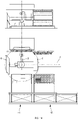
- the preferred embodiments of the invention are based on the improvement of a current standard solution and its functions, such as for example the robotic bending cell proposed by the firm Bystronic (4922 Thunstetten, Switzerland) but in no way limiting or binding, insofar as most manufacturers offer the same functions for this type of cell.
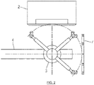
- This cell will be referred to hereafter as the “standard cell”. It is this type of cell which is represented on the FIG. 1 .
- press brakes for Automatic Guided Vehicles, these robots which move autonomously without human intervention, thanks to any guiding technique
- AGVs Automatic Guided Vehicles, these robots which move autonomously without human intervention, thanks to any guiding technique
- optical or mechanical recognition systems systems for turning over or picking up parts during the process ( regrip )
- bending tool magazines automated or not
- gripping systems for parts handled by the robot, thickness control systems, etc.
- a first technical objective is to ensure the availability of the tools necessary to guarantee a very long autonomy of the cell (see “conceptual objectives” above ).
- the press brake 2 is offset from the track 4 (or moved from the current configuration of the standard cell) and the tool shelf 7 is positioned perpendicular to the track.
- This layout allows the robot to position itself so that its vertical axis of rotation is equidistant from the tool shelf and the press brake.
- a simple 90° rotation allows the robot to be alternately facing the shelf or facing the press brake.
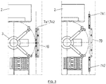
- the shelf located in the foreground 7A with respect to track 4 is divided into two elements 7A1 and 7A2. These two elements are mounted on a rolling rail 70 placed on the ground and are guided by a guide rail in their upper part (not shown).
- the two elements 7A1 and 7A2 are mobile and can move inwards or outwards on the rail by any mechanical means (motorized or not) in order to allow the robot to access the tools of the shelf located at the bottom. 'background.
- a solution comprising more than two shelving planes is also possible.
- the tool shelf 7 is positioned in a plane parallel to the plane of the front face of the press brake 2.
- the tool shelf 7 is mounted on a rolling rail 70 placed on the ground and is guided by a guide rail 71 in its upper part.
- the shelf 7 is mobile and can be moved by any mechanical means (with or without motorization) in order to position itself opposite the press brake 2, parallel to the aprons of the machine.
- the shelf 7 is provided with a window 72 allowing access to the grooves for fixing the punches and dies (not shown) on the press brake 2.
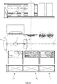
- FIG. 5 there is a duplication of the shelves 7A, 7B and a positioning thereof to the left and right of the machine respectively.
- the shelves 7A, 7B are both movable as indicated above to allow their displacement vis-à-vis the press brake 2.
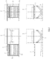
- the system differs from proposal N°3 in that it includes several shelves 7C juxtaposed parallel to each other and whose height is less than that of the bottom apron 25 of the press brake 2.
- the shelves 7C are surrounded by a supporting structure provided with a device making it possible to position each of them opposite a raceway 70 parallel to the lower deck 25 of the press brake 2.
- the system is composed of two juxtaposed shelves 7.
- Each shelf is equipped with tools on its two faces 7A, 7B.
- the shelves are placed on a base allowing their rotation at 180°.
- the tools on both sides of the shelf are thus made accessible to the robot.
- the rotation of the shelves is motorized and controlled by the cell software according to the tools called by the bending program.
- Each shelf has for example a storage capacity of 40 m.
- the angle of inclination of the shelves makes it possible to optimize the movements of the robot.
- N 3, 4, 5, 6, etc.
- the capacity in number of tools increases by 50%.
- the advantage of these compact configurations is to provide a lot of possibilities in a small space.
- the advantage of this eighth solution is in particular the possibility of coupling different functions on the same shelf, such as bending tools on one side, grippers on the other or a "regrip" system on one side and a thickness control on the other, etc.
- a second technical objective is to maximize the number of grippers available in the cell.
- all the above considerations concerning bending tool magazines are of course valid for the storage of grippers.
- Automated (linear) warehouse means an automated storage system comprising storage spaces arranged along aisles on the ground and/or at height.
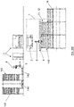
- the automated warehouse is actually made up of storage towers (see for example FIG. 16 , reference 143) juxtaposed and arranged in line over a variable length in relation to the dimensions of the workshop and the number of machines connected to the store.
- the magazine can generally comprise two rows of parallel towers. Each tower can accommodate a number of 141 pallets, the total number of these pallets depending on the height of the towers.
- the standardized pallets of the automated warehouse can be used as support for other forms of palletization, such as euro-pallets.
- the pallets are equipped with hooks allowing their extraction by various devices located either on the side of the internal face of the towers, or on the side of their external face.
- a device generally referred to as a stacker crane 144 moves longitudinally along the towers along the entire length of the store.
- the stacker crane is equipped with a chain conveyor system that can move vertically over the entire height of the towers and allows the pallets to be extracted with a view to moving them to another location in the store.
- the combination of vertical and horizontal movements allows the stacker crane to access all of the pallet housings in the store and to distribute the pallets from one housing to another, at any location in the store.
- Other standard functions of automated stores can be installed on the periphery of the external face of the towers of the store in order to allow the introduction of pallets into the store or, conversely, to extract pallets in order to feed the machines. and workstations located on the outskirts of the store.
- the entries and exits of material from the automated store are carried out by any machine whose movement coordination and guidance are carried out by management software.
- These machines can be for example not only stacker cranes, but also conveyors, gantries, carousels, etc. that can move parts, pallets, trays, crates, etc.
- the stocked material may consist of lengths of flat sheets, bent parts, pallets including grippers, bending tools or inserts, storage boxes for finished parts with small dimensions, etc.
- the solution consists in automatically supplying the cell with parts to be bent (in a specific area 11 called raw in ).
- the supply is carried out from the towers 141 of the automated warehouse 14, generally on pallets for depositing incoming parts 15.
- the solution consists, next to the aforementioned supply of sheets from the automated store 14 in the raw in area 11, in an automatic evacuation of the folded parts to the automated store 14, from pallets 16 located in the area removal of bent parts (known as raw out ) 12, with a view to storing them or dispatching them to another station in the workshop.
- the solution consists in coupling to the automated store 14 a tool and gripper sharing system 17 which also interfaces with the cell, just like the raw in and the raw out ( Tools & Grippers Sharing System).
- the direct connection of the folding cell 1 to the automated store 14 could find a particularly interesting technical advantage in the fact of allowing a sharing between several cells 1, connected to the store 14 of the folding tools and grippers.
- the solution consists of a combination of raw in and raw out on a single pallet 15, 16. This solution is particularly advantageous for mini-cells where the press brake is small (1 - 1.5 m) .
- the present proposal consists in grouping together on a single and same pallet 15, 16 the various elements to be introduced into the cell and to be evacuated from the cell.
- a chain conveyor provides the cell with everything it needs to perform a given task: the parts to be bent 20, a deposit "surface” for the bent parts 21 or containers of the "drop box” type 19, the specific tools 17 required for folding or gripping the parts, dividers 18 for stacking the folded parts in layers, etc.
- the grippers will be arranged flat in the automated store and vertically on the shelves of the cell.
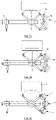
- the "regrip system” 5 is positioned to the far left of the cell. All the current operations are accessible to the perimeter of rotation of the robot 3. For example, it slides the tool shelf (in this case there are two sliding shelves 7A, 7B), takes the sheet metal to be bent coming from the automated store and returns the piece once folded to the latter.
- the store has two entrances 11, 12. We also see on the far right two double rotating shelves 7A, 7B with grippers 9 on both sides.
- the automated store has three entries 11, 12, 17, respectively one for the flat parts, another for the bent parts and finally a third for specific tools or grippers and the inserts intended for the stacking of bent parts.
- Track 4 is longer than in the first case.
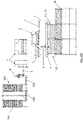
- the grippers are located on a horizontal or vertical wall, where they are housed by the robot, from the magazine.
- the grippers 9 can advantageously be fixed to the sheet metal of the wall using four-finger intermediate fixing plates (not shown). To do this, the sheet has regular perforations on the abscissa and ordinate (eg every 5cm), which will promote optimized nesting of the grippers.
- the fingers of these plates are terminated by tapered turned parts (or shouldered pins).
- a repositioning frame is placed at the extreme left of the track.
- the robot carriage which moves along the rack is extended compared to the previous solutions and supports at its rightmost end the "regrip" system 5. Again all the functions are accessible within the robot's rotation perimeter (e.g. workpiece thickness measurement).
- FIG. 15 there is a variant of the third embodiment where the store comprises three entrances 11, 12, 17 instead of two entrances 11, 12.
- the nature of the tool/gripper shelves 7, 7A, 7B (sliding, rotating) as well as their arrangement in the cell are similar to the situation in the first two embodiments.
- the supply can be done via a connection to the automated warehouse by a small automated kart that can support a pallet for example by means of a pantograph and moving by means of a GPS (or any other guidance system) under the shelves of the automated store.
- the track in this case is miniaturized and the robot has much faster movements, and is very close to all functions/areas (fetch parts to bend, retrieve bent parts, etc.).
- FIGS. 16A to 16D further show a preferably compact variant for a folding cell associated with an automated magazine (respectively called “small”, “medium” and “large” cell according to an arbitrary/relative classification).
- the palletization system is mixed (a single input/output).
- a conveyor/chain pallet extractor 142 ensures the transfer of the parts (to bend, bent) and of the tools or other accessories from the automated store 14 to the cell 1 and vice versa.
- an intermediate raw in / raw out zone 11, 12 can be advantageously used for the transfer between the magazine and the cell (and vice versa).
- the automated store 14 consists of two parallel rows of towers 141 for the storage of pallets 143 in height, the storage positions being accessible by means of an elevator 144 (and/or an AGV) which can also move longitudinally along the store.
- the robot 3 moves on a track 4 with an axis parallel both to the apron of the press brake 2 and to the external face (cell side) of the automated store, so that the robot 3 is always brought to face the press brake 2 and the automated store 14.
- the axis of the track 4 is approximately equidistant from the press brake 2 and the automated store 14. This configuration allows a compactness of the cell.
- the track 4 is advantageously suspended, so that a conflict is avoided between the space of the robot and that of the pallet puller 142.
- the amplitude of the movement of the robot is greatly reduced.
- the outer face of the latter can advantageously be provided with supports for grippers or bending tools (not shown).
- This configuration is particularly suitable for cells equipped with 1-1.5 m press brakes, but it is not excluded in the case of cells equipped with larger press brakes.
- the figure 16D shows a layout where, in the case of a cell where space permits, the press brake is approximately centered across the width of the cell rather than being aligned with one of the magazine towers.
- the press brake is approximately centered across the width of the cell rather than being aligned with one of the magazine towers.
- tool shelves 7 sliding, rotating, etc.
Landscapes
- Engineering & Computer Science (AREA)
- Mechanical Engineering (AREA)
- General Engineering & Computer Science (AREA)
- Manufacturing & Machinery (AREA)
- Quality & Reliability (AREA)
- Physics & Mathematics (AREA)
- General Physics & Mathematics (AREA)
- Automation & Control Theory (AREA)
- Bending Of Plates, Rods, And Pipes (AREA)
- Warehouses Or Storage Devices (AREA)
- Manipulator (AREA)
- Mounting, Exchange, And Manufacturing Of Dies (AREA)
Priority Applications (1)
| Application Number | Priority Date | Filing Date | Title |
|---|---|---|---|
| EP22212978.5A EP4186606A3 (fr) | 2020-10-28 | 2021-10-26 | Cellule de pliage de toles entierement automatisee |
Applications Claiming Priority (4)
| Application Number | Priority Date | Filing Date | Title |
|---|---|---|---|
| EP20204355 | 2020-10-28 | ||
| EP21156189 | 2021-02-10 | ||
| EP21160343 | 2021-03-02 | ||
| PCT/EP2021/079727 WO2022090258A1 (fr) | 2020-10-28 | 2021-10-26 | Cellule de pliage de toles entierement automatisee |
Related Child Applications (1)
| Application Number | Title | Priority Date | Filing Date |
|---|---|---|---|
| EP22212978.5A Division EP4186606A3 (fr) | 2020-10-28 | 2021-10-26 | Cellule de pliage de toles entierement automatisee |
Publications (2)
| Publication Number | Publication Date |
|---|---|
| EP4017658A1 EP4017658A1 (fr) | 2022-06-29 |
| EP4017658B1 true EP4017658B1 (fr) | 2022-12-14 |
Family
ID=78414038
Family Applications (3)
| Application Number | Title | Priority Date | Filing Date |
|---|---|---|---|
| EP21799050.6A Active EP4017658B1 (fr) | 2020-10-28 | 2021-10-26 | Cellule de pliage de toles entierement automatisee |
| EP22212978.5A Withdrawn EP4186606A3 (fr) | 2020-10-28 | 2021-10-26 | Cellule de pliage de toles entierement automatisee |
| EP21801493.4A Active EP4017659B1 (fr) | 2020-10-28 | 2021-10-27 | Ensemble de moyens de rangement et stockage pour cellule de pliage de toles entierement automatisee |
Family Applications After (2)
| Application Number | Title | Priority Date | Filing Date |
|---|---|---|---|
| EP22212978.5A Withdrawn EP4186606A3 (fr) | 2020-10-28 | 2021-10-26 | Cellule de pliage de toles entierement automatisee |
| EP21801493.4A Active EP4017659B1 (fr) | 2020-10-28 | 2021-10-27 | Ensemble de moyens de rangement et stockage pour cellule de pliage de toles entierement automatisee |
Country Status (5)
| Country | Link |
|---|---|
| US (1) | US20230405659A1 (enExample) |
| EP (3) | EP4017658B1 (enExample) |
| JP (1) | JP2023547546A (enExample) |
| CA (1) | CA3200279A1 (enExample) |
| WO (2) | WO2022090258A1 (enExample) |
Cited By (1)
| Publication number | Priority date | Publication date | Assignee | Title |
|---|---|---|---|---|
| AT528047A1 (de) * | 2024-02-26 | 2025-09-15 | Trumpf Maschinen Austria Gmbh & Co Kg | Biegemaschine mit Handhabungsroboter |
Families Citing this family (3)
| Publication number | Priority date | Publication date | Assignee | Title |
|---|---|---|---|---|
| CN115382951B (zh) * | 2022-09-22 | 2023-04-07 | 东莞新永腾自动化设备有限公司 | 一种多功能铜铝排加工机 |
| US20240353815A1 (en) * | 2023-04-21 | 2024-10-24 | GM Global Technology Operations LLC | System and method for locally re-shaping a workpiece |
| EP4696429A1 (en) * | 2024-08-16 | 2026-02-18 | Nivora IP B.V. | Combination of a press brake and a serial manipulator |
Citations (36)
| Publication number | Priority date | Publication date | Assignee | Title |
|---|---|---|---|---|
| US4007140A (en) | 1972-11-01 | 1977-02-08 | Imperial Chemical Industries Limited | Tertiary amines as catalysts in polyurethane manufacture |
| JPS5973021U (ja) | 1982-11-09 | 1984-05-17 | 株式会社アマダ | 金型交換装置 |
| JPS6024229A (ja) | 1983-07-19 | 1985-02-06 | Amada Co Ltd | 金型ラツク |
| US5062535A (en) | 1991-02-15 | 1991-11-05 | Frank Potter | Side-sliding storage rack for 3480 cartridges |
| EP0515798A1 (de) | 1991-05-17 | 1992-12-02 | HIRSCHMANN GmbH | Magazin für Werkzeuge und/oder Werkstücke mit Wechselvorrichtung |
| US5226549A (en) | 1992-02-05 | 1993-07-13 | Engineered Data Products, Inc. | Cartridge protector for sliding rack storage systems and method therefore |
| JPH06234018A (ja) | 1993-02-09 | 1994-08-23 | Komatsu Ltd | プレスブレーキの自動金型交換装置 |
| DE19510498A1 (de) | 1995-03-23 | 1996-09-26 | Heckert Chemn Werkzeugmasch | Werkzeugwechseleinrichtung |
| DE202005008202U1 (de) | 2005-05-25 | 2005-08-04 | hb Collection Möbelvertriebs GmbH | Schiebetürenschrank |
| EP1733840A1 (de) | 2005-06-18 | 2006-12-20 | Alfing Kessler Sondermaschinen GmbH | Bearbeitungsmaschinenanordnung mit Roboter und Werkzeugmagazin |
| EP1930119A1 (de) | 2006-12-08 | 2008-06-11 | Trumpf Sachsen GmbH | Maschinelle Anlage zum Bearbeiten von Werkstücken |
| EP2138247A2 (de) | 2008-06-23 | 2009-12-30 | Trumpf Maschinen Austria GmbH & CO. KG. | Fertigungsanlage mit Biegepresse |
| EP2177326A2 (en) | 2008-10-14 | 2010-04-21 | Safan B.V. | Method for aligning a workpiece to a robot |
| JP2011150571A (ja) | 2010-01-22 | 2011-08-04 | Amada Co Ltd | 曲げ加工システム及びその方法 |
| DE102010001665A1 (de) | 2010-02-08 | 2011-08-11 | Osram Gesellschaft mit beschränkter Haftung, 81543 | Reduktion der durch Rückreflektion in die Elektrode einer Entladungslampe eingetragenen Leistung |
| WO2012037592A1 (de) | 2010-09-21 | 2012-03-29 | Trumpf Maschinen Austria Gmbh & Co.Kg. | Fertigungszelle mit einer werkteil-transfereinrichtung und transporteinrichtung für werkteile und teileträger |
| WO2012063710A1 (ja) | 2010-11-10 | 2012-05-18 | 株式会社 アマダ | 長尺材曲げ加工用ロボットハンド、及び、長尺材曲げ加工システム |
| DE102011054395A1 (de) | 2011-10-11 | 2013-04-11 | Würmseher Möbelfabrik-GmbH | Schieberegal |
| BG111452A (bg) | 2013-04-22 | 2014-10-31 | "Арп" Оод | Автоматична линия за производство на детайли за изработване на стоманени врати |
| EP2865458A1 (en) | 2012-06-25 | 2015-04-29 | AMADA Company, Ltd. | Stocker for mounting molds, mold storage device, method for replacing molds by means of mold/hand storage device and robot, and control device for method |
| JP2015120182A (ja) | 2013-12-24 | 2015-07-02 | 株式会社アマダホールディングス | 金型収納ラック |
| EP2992995A1 (en) | 2014-09-08 | 2016-03-09 | DMG Mori Co., Ltd. | Automatic tool changer and machine tool |
| WO2016055906A1 (de) | 2014-10-06 | 2016-04-14 | Bystronic Laser Ag | Biegepresse |
| WO2017212386A1 (en) | 2016-06-06 | 2017-12-14 | Dalma S.R.L. | Tool-loader storage unit for a tool machine |
| US20180056357A1 (en) | 2014-12-15 | 2018-03-01 | Trumpf Maschinen Austria Gmbh & Co. Kg. | Production system with a manipulation device |
| WO2018073312A1 (de) | 2016-10-21 | 2018-04-26 | Bystronic Laser Ag | Positionierbare roboterzelle, fertigungseinrichtung mit einer fertigungsvorrichtung und mit positionierbare roboterzelle sowie verfahren zum betrieb einer solchen positionierbaren roboterzelle |
| EP3444685A1 (de) | 2017-08-17 | 2019-02-20 | CLAAS Selbstfahrende Erntemaschinen GmbH | Fertigungszelle und verfahren zum rüsten einer fertigungszelle |
| DE102018128953A1 (de) | 2017-11-28 | 2019-05-29 | Fanuc Corporation | Bearbeitungssystem |
| CN110076256A (zh) | 2019-05-24 | 2019-08-02 | 广义智能智造(深圳)有限公司 | 一种折弯机自动上下料装置 |
| CN110153314A (zh) | 2019-05-30 | 2019-08-23 | 无锡金红鹰工业自动化有限公司 | 钣金折弯工艺以及用于该工艺的折弯装置 |
| CN110252859A (zh) | 2019-08-07 | 2019-09-20 | 河南万华畜牧设备有限公司 | 全数控机器人折弯单元 |
| DE102018110955A1 (de) | 2018-05-08 | 2019-11-14 | Bystronic Laser Ag | Werkzeugaufbewahrungsvorrichtung für eine Werkzeugmaschine und Werkzeugmaschine |
| CN210146830U (zh) | 2019-05-24 | 2020-03-17 | 广义智能智造(深圳)有限公司 | 一种机器人自动折弯设备 |
| CN210231085U (zh) | 2019-08-07 | 2020-04-03 | 河南万华畜牧设备有限公司 | 全数控机器人折弯单元 |
| CN111151602A (zh) | 2020-01-21 | 2020-05-15 | 上海新时达机器人有限公司 | 一种具有容错功能的机器人折弯系统及方法 |
| EP3715047A2 (de) | 2019-03-25 | 2020-09-30 | Erowa AG | Anordnung zur bearbeitung von werkstücken |
Family Cites Families (7)
| Publication number | Priority date | Publication date | Assignee | Title |
|---|---|---|---|---|
| JP3131269B2 (ja) * | 1991-03-22 | 2001-01-31 | 株式会社アマダ | 板材加工装置 |
| JP3145211B2 (ja) * | 1992-11-12 | 2001-03-12 | 株式会社アマダ | 板金加工システム |
| JP3839134B2 (ja) * | 1997-06-11 | 2006-11-01 | 株式会社アマダ | プレスブレーキ |
| DE202013004648U1 (de) * | 2013-05-17 | 2013-08-23 | V2 Vorentwicklung & Vertrieb Gmbh | Wagen mit einem senkrecht angeordneten Maschengitter zum Anbringen von unterschiedlichen Elementen |
| US10293478B2 (en) | 2017-06-06 | 2019-05-21 | Larry Mitchell Grela | Storage hutch assembly |
| SE541391C2 (en) | 2017-12-22 | 2019-09-10 | Hedin Lagan Ab | Sheet metal press system and method used in connection therewith |
| US10576526B2 (en) * | 2018-07-03 | 2020-03-03 | Komatsu Industries Corporation | Workpiece conveying system, and workpiece conveying method |
-
2021
- 2021-10-26 EP EP21799050.6A patent/EP4017658B1/fr active Active
- 2021-10-26 US US18/250,375 patent/US20230405659A1/en active Pending
- 2021-10-26 CA CA3200279A patent/CA3200279A1/en active Pending
- 2021-10-26 JP JP2023527255A patent/JP2023547546A/ja active Pending
- 2021-10-26 EP EP22212978.5A patent/EP4186606A3/fr not_active Withdrawn
- 2021-10-26 WO PCT/EP2021/079727 patent/WO2022090258A1/fr not_active Ceased
- 2021-10-27 EP EP21801493.4A patent/EP4017659B1/fr active Active
- 2021-10-27 WO PCT/EP2021/079776 patent/WO2022090287A1/fr not_active Ceased
Patent Citations (37)
| Publication number | Priority date | Publication date | Assignee | Title |
|---|---|---|---|---|
| US4007140A (en) | 1972-11-01 | 1977-02-08 | Imperial Chemical Industries Limited | Tertiary amines as catalysts in polyurethane manufacture |
| JPS5973021U (ja) | 1982-11-09 | 1984-05-17 | 株式会社アマダ | 金型交換装置 |
| JPS6024229A (ja) | 1983-07-19 | 1985-02-06 | Amada Co Ltd | 金型ラツク |
| US5062535A (en) | 1991-02-15 | 1991-11-05 | Frank Potter | Side-sliding storage rack for 3480 cartridges |
| EP0515798A1 (de) | 1991-05-17 | 1992-12-02 | HIRSCHMANN GmbH | Magazin für Werkzeuge und/oder Werkstücke mit Wechselvorrichtung |
| US5226549A (en) | 1992-02-05 | 1993-07-13 | Engineered Data Products, Inc. | Cartridge protector for sliding rack storage systems and method therefore |
| JPH06234018A (ja) | 1993-02-09 | 1994-08-23 | Komatsu Ltd | プレスブレーキの自動金型交換装置 |
| DE19510498A1 (de) | 1995-03-23 | 1996-09-26 | Heckert Chemn Werkzeugmasch | Werkzeugwechseleinrichtung |
| DE202005008202U1 (de) | 2005-05-25 | 2005-08-04 | hb Collection Möbelvertriebs GmbH | Schiebetürenschrank |
| EP1733840A1 (de) | 2005-06-18 | 2006-12-20 | Alfing Kessler Sondermaschinen GmbH | Bearbeitungsmaschinenanordnung mit Roboter und Werkzeugmagazin |
| EP1930119A1 (de) | 2006-12-08 | 2008-06-11 | Trumpf Sachsen GmbH | Maschinelle Anlage zum Bearbeiten von Werkstücken |
| EP2138247A2 (de) | 2008-06-23 | 2009-12-30 | Trumpf Maschinen Austria GmbH & CO. KG. | Fertigungsanlage mit Biegepresse |
| EP2177326A2 (en) | 2008-10-14 | 2010-04-21 | Safan B.V. | Method for aligning a workpiece to a robot |
| JP2011150571A (ja) | 2010-01-22 | 2011-08-04 | Amada Co Ltd | 曲げ加工システム及びその方法 |
| DE102010001665A1 (de) | 2010-02-08 | 2011-08-11 | Osram Gesellschaft mit beschränkter Haftung, 81543 | Reduktion der durch Rückreflektion in die Elektrode einer Entladungslampe eingetragenen Leistung |
| WO2012037592A1 (de) | 2010-09-21 | 2012-03-29 | Trumpf Maschinen Austria Gmbh & Co.Kg. | Fertigungszelle mit einer werkteil-transfereinrichtung und transporteinrichtung für werkteile und teileträger |
| WO2012063710A1 (ja) | 2010-11-10 | 2012-05-18 | 株式会社 アマダ | 長尺材曲げ加工用ロボットハンド、及び、長尺材曲げ加工システム |
| DE102011054395A1 (de) | 2011-10-11 | 2013-04-11 | Würmseher Möbelfabrik-GmbH | Schieberegal |
| EP2865458A1 (en) | 2012-06-25 | 2015-04-29 | AMADA Company, Ltd. | Stocker for mounting molds, mold storage device, method for replacing molds by means of mold/hand storage device and robot, and control device for method |
| BG111452A (bg) | 2013-04-22 | 2014-10-31 | "Арп" Оод | Автоматична линия за производство на детайли за изработване на стоманени врати |
| JP2015120182A (ja) | 2013-12-24 | 2015-07-02 | 株式会社アマダホールディングス | 金型収納ラック |
| EP2992995A1 (en) | 2014-09-08 | 2016-03-09 | DMG Mori Co., Ltd. | Automatic tool changer and machine tool |
| WO2016055906A1 (de) | 2014-10-06 | 2016-04-14 | Bystronic Laser Ag | Biegepresse |
| US20180056357A1 (en) | 2014-12-15 | 2018-03-01 | Trumpf Maschinen Austria Gmbh & Co. Kg. | Production system with a manipulation device |
| WO2017212386A1 (en) | 2016-06-06 | 2017-12-14 | Dalma S.R.L. | Tool-loader storage unit for a tool machine |
| WO2018073312A1 (de) | 2016-10-21 | 2018-04-26 | Bystronic Laser Ag | Positionierbare roboterzelle, fertigungseinrichtung mit einer fertigungsvorrichtung und mit positionierbare roboterzelle sowie verfahren zum betrieb einer solchen positionierbaren roboterzelle |
| EP3444685A1 (de) | 2017-08-17 | 2019-02-20 | CLAAS Selbstfahrende Erntemaschinen GmbH | Fertigungszelle und verfahren zum rüsten einer fertigungszelle |
| DE102018128953A1 (de) | 2017-11-28 | 2019-05-29 | Fanuc Corporation | Bearbeitungssystem |
| WO2019214843A1 (de) | 2018-05-08 | 2019-11-14 | Bystronic Laser Ag | Werkzeugaufbewahrungsvorrichtung für eine werkzeugmaschine und werkzeugmaschine |
| DE102018110955A1 (de) | 2018-05-08 | 2019-11-14 | Bystronic Laser Ag | Werkzeugaufbewahrungsvorrichtung für eine Werkzeugmaschine und Werkzeugmaschine |
| EP3715047A2 (de) | 2019-03-25 | 2020-09-30 | Erowa AG | Anordnung zur bearbeitung von werkstücken |
| CN110076256A (zh) | 2019-05-24 | 2019-08-02 | 广义智能智造(深圳)有限公司 | 一种折弯机自动上下料装置 |
| CN210146830U (zh) | 2019-05-24 | 2020-03-17 | 广义智能智造(深圳)有限公司 | 一种机器人自动折弯设备 |
| CN110153314A (zh) | 2019-05-30 | 2019-08-23 | 无锡金红鹰工业自动化有限公司 | 钣金折弯工艺以及用于该工艺的折弯装置 |
| CN110252859A (zh) | 2019-08-07 | 2019-09-20 | 河南万华畜牧设备有限公司 | 全数控机器人折弯单元 |
| CN210231085U (zh) | 2019-08-07 | 2020-04-03 | 河南万华畜牧设备有限公司 | 全数控机器人折弯单元 |
| CN111151602A (zh) | 2020-01-21 | 2020-05-15 | 上海新时达机器人有限公司 | 一种具有容错功能的机器人折弯系统及方法 |
Non-Patent Citations (6)
| Title |
|---|
| ANONYMOUS: "Hand in hand wie cobots sich nutzlich machen", BYSTRONIC WORLD DAS MAGAZINE UBER SCHEIDEN BIEGEN AND AUTOMATION, 1 March 2020 (2020-03-01), pages 1 - 32, XP093131336 |
| BYSTRONIC: "Bystronic Automation Bending: Bending Cell (English)", YOUTUBE, 1 May 2020 (2020-05-01), XP093112937, Retrieved from the Internet <URL:https://www.youtube.com/watch?v=KudESdfUSAg> [retrieved on 20231218] |
| BYSTRONIC: "Bystronic: Smart Factory (English)", 8 November 2018 (2018-11-08), pages 1 - 2, XP093131340, Retrieved from the Internet <URL:https://www.youtube.com/watch?v=7chg5KWVoRA> [retrieved on 20240214] |
| TRUMPF: "Broschüre zu Biegemaschinen der Fa. Trumpf", TRUMPF MASCHINEN AUSTRIA GMBH & CO. KG., 1 March 2020 (2020-03-01), pages 1 - 56, XP093112936, [retrieved on 20231218] |
| TRUMPF: "Video zum "STOPA-Großlagersystem"", TRUMPF MASCHINEN AUSTRIA GMBH & CO. KG., 19 July 2020 (2020-07-19), XP093112933, [retrieved on 20231218] |
| TRUMPF: "Video zur Universalbiegezelle "TruBend Cell 5000" der Fa. Trumpf", TRUMPF MASCHINEN AUSTRIA GMBH & CO. KG., 1 October 2020 (2020-10-01), XP093112935, [retrieved on 20231218] |
Cited By (1)
| Publication number | Priority date | Publication date | Assignee | Title |
|---|---|---|---|---|
| AT528047A1 (de) * | 2024-02-26 | 2025-09-15 | Trumpf Maschinen Austria Gmbh & Co Kg | Biegemaschine mit Handhabungsroboter |
Also Published As
| Publication number | Publication date |
|---|---|
| EP4186606A2 (fr) | 2023-05-31 |
| WO2022090287A1 (fr) | 2022-05-05 |
| US20230405659A1 (en) | 2023-12-21 |
| EP4017658A1 (fr) | 2022-06-29 |
| WO2022090258A1 (fr) | 2022-05-05 |
| EP4017659B1 (fr) | 2023-03-29 |
| EP4017659A1 (fr) | 2022-06-29 |
| CA3200279A1 (en) | 2022-05-05 |
| EP4186606A3 (fr) | 2023-08-30 |
| JP2023547546A (ja) | 2023-11-10 |
Similar Documents
| Publication | Publication Date | Title |
|---|---|---|
| EP4017658B1 (fr) | Cellule de pliage de toles entierement automatisee | |
| EP0572650B1 (fr) | Magasin de stockage automatise et nouveau type de chariot permettant la mise en place ou l'extraction des produits a l'interieur des zones de stockage | |
| EP3245147B1 (fr) | Système et procédé de séquencement pour au moins un poste de préparation | |
| FR2787771A1 (fr) | Procede de stockage et entrepot automatise | |
| EP4179481A1 (fr) | Systeme et procede de gestion d'une pluralite de robots mobiles pour la preparation de commandes de produits stockes dans un entrepot | |
| FR3007310A1 (fr) | Unite de production de produits manufactures comprenant un magasin automotique apte a etre associe a l execution de taches d un processus de fabrication | |
| EP0761578A1 (fr) | Dispositif d'empilage des couches sur une palette et dispositif de palettisation | |
| WO2022187557A2 (en) | Automated decant system | |
| WO2024175312A1 (fr) | Système et convoyeur permuteur de palettes | |
| EP1086910A1 (fr) | Magasin de stockage compact automatisé | |
| EP3389921B1 (fr) | Poste d'assemblage d'une ligne de fabrication industrielle | |
| EP2899146B1 (fr) | Procédé et installation de gestion d'un flux d'articles au niveau d'une zone tampon | |
| WO2021176184A9 (fr) | Système et procédé de transfert de contenants dans un entrepôt de stockage | |
| WO2024033206A1 (fr) | Systeme de preparation de commandes de produits stockes dans un entrepot multi-niveaux et preleves par une pluralite de robots mobiles autonomes | |
| GB2638776A (en) | An order processing system and a method of order processing | |
| EP0408638B1 (fr) | Procede et dispositif d'accumulation et de convoyage d'articles pour presenter ces articles a un poste fixe dans un ordre arbitraire determine | |
| FR2976199A1 (fr) | Agencement de presses disposees les unes a la suite des autres pour le travail de pieces en tole et presse implantee dans un tel agencement | |
| EP4140919A1 (fr) | Convoyeur permutateur de palettes | |
| EP4651049A1 (fr) | Système pour la constitution automatique de palettes supportant un ensemble de colis par détermination préalable d'un plan de palette optimisé | |
| TW202525670A (zh) | 物品分類設備 | |
| JPH02139160A (ja) | ロボットの作業設備 |
Legal Events
| Date | Code | Title | Description |
|---|---|---|---|
| STAA | Information on the status of an ep patent application or granted ep patent |
Free format text: STATUS: UNKNOWN |
|
| STAA | Information on the status of an ep patent application or granted ep patent |
Free format text: STATUS: THE INTERNATIONAL PUBLICATION HAS BEEN MADE |
|
| PUAI | Public reference made under article 153(3) epc to a published international application that has entered the european phase |
Free format text: ORIGINAL CODE: 0009012 |
|
| STAA | Information on the status of an ep patent application or granted ep patent |
Free format text: STATUS: REQUEST FOR EXAMINATION WAS MADE |
|
| GRAJ | Information related to disapproval of communication of intention to grant by the applicant or resumption of examination proceedings by the epo deleted |
Free format text: ORIGINAL CODE: EPIDOSDIGR1 |
|
| GRAP | Despatch of communication of intention to grant a patent |
Free format text: ORIGINAL CODE: EPIDOSNIGR1 |
|
| GRAP | Despatch of communication of intention to grant a patent |
Free format text: ORIGINAL CODE: EPIDOSNIGR1 |
|
| STAA | Information on the status of an ep patent application or granted ep patent |
Free format text: STATUS: GRANT OF PATENT IS INTENDED |
|
| 17P | Request for examination filed |
Effective date: 20220228 |
|
| AK | Designated contracting states |
Kind code of ref document: A1 Designated state(s): AL AT BE BG CH CY CZ DE DK EE ES FI FR GB GR HR HU IE IS IT LI LT LU LV MC MK MT NL NO PL PT RO RS SE SI SK SM TR |
|
| INTC | Intention to grant announced (deleted) | ||
| RIN1 | Information on inventor provided before grant (corrected) |
Inventor name: PITANCE, GERARD |
|
| INTG | Intention to grant announced |
Effective date: 20220628 |
|
| GRAS | Grant fee paid |
Free format text: ORIGINAL CODE: EPIDOSNIGR3 |
|
| GRAA | (expected) grant |
Free format text: ORIGINAL CODE: 0009210 |
|
| STAA | Information on the status of an ep patent application or granted ep patent |
Free format text: STATUS: THE PATENT HAS BEEN GRANTED |
|
| AK | Designated contracting states |
Kind code of ref document: B1 Designated state(s): AL AT BE BG CH CY CZ DE DK EE ES FI FR GB GR HR HU IE IS IT LI LT LU LV MC MK MT NL NO PL PT RO RS SE SI SK SM TR |
|
| DAV | Request for validation of the european patent (deleted) | ||
| DAX | Request for extension of the european patent (deleted) | ||
| REG | Reference to a national code |
Ref country code: GB Ref legal event code: FG4D Free format text: NOT ENGLISH |
|
| REG | Reference to a national code |
Ref country code: CH Ref legal event code: EP |
|
| REG | Reference to a national code |
Ref country code: DE Ref legal event code: R096 Ref document number: 602021000993 Country of ref document: DE |
|
| REG | Reference to a national code |
Ref country code: IE Ref legal event code: FG4D Free format text: LANGUAGE OF EP DOCUMENT: FRENCH |
|
| REG | Reference to a national code |
Ref country code: AT Ref legal event code: REF Ref document number: 1537373 Country of ref document: AT Kind code of ref document: T Effective date: 20230115 |
|
| REG | Reference to a national code |
Ref country code: LT Ref legal event code: MG9D |
|
| REG | Reference to a national code |
Ref country code: NL Ref legal event code: MP Effective date: 20221214 |
|
| PG25 | Lapsed in a contracting state [announced via postgrant information from national office to epo] |
Ref country code: SE Free format text: LAPSE BECAUSE OF FAILURE TO SUBMIT A TRANSLATION OF THE DESCRIPTION OR TO PAY THE FEE WITHIN THE PRESCRIBED TIME-LIMIT Effective date: 20221214 Ref country code: NO Free format text: LAPSE BECAUSE OF FAILURE TO SUBMIT A TRANSLATION OF THE DESCRIPTION OR TO PAY THE FEE WITHIN THE PRESCRIBED TIME-LIMIT Effective date: 20230314 Ref country code: LT Free format text: LAPSE BECAUSE OF FAILURE TO SUBMIT A TRANSLATION OF THE DESCRIPTION OR TO PAY THE FEE WITHIN THE PRESCRIBED TIME-LIMIT Effective date: 20221214 Ref country code: FI Free format text: LAPSE BECAUSE OF FAILURE TO SUBMIT A TRANSLATION OF THE DESCRIPTION OR TO PAY THE FEE WITHIN THE PRESCRIBED TIME-LIMIT Effective date: 20221214 |
|
| REG | Reference to a national code |
Ref country code: AT Ref legal event code: MK05 Ref document number: 1537373 Country of ref document: AT Kind code of ref document: T Effective date: 20221214 |
|
| PG25 | Lapsed in a contracting state [announced via postgrant information from national office to epo] |
Ref country code: RS Free format text: LAPSE BECAUSE OF FAILURE TO SUBMIT A TRANSLATION OF THE DESCRIPTION OR TO PAY THE FEE WITHIN THE PRESCRIBED TIME-LIMIT Effective date: 20221214 Ref country code: LV Free format text: LAPSE BECAUSE OF FAILURE TO SUBMIT A TRANSLATION OF THE DESCRIPTION OR TO PAY THE FEE WITHIN THE PRESCRIBED TIME-LIMIT Effective date: 20221214 Ref country code: HR Free format text: LAPSE BECAUSE OF FAILURE TO SUBMIT A TRANSLATION OF THE DESCRIPTION OR TO PAY THE FEE WITHIN THE PRESCRIBED TIME-LIMIT Effective date: 20221214 Ref country code: GR Free format text: LAPSE BECAUSE OF FAILURE TO SUBMIT A TRANSLATION OF THE DESCRIPTION OR TO PAY THE FEE WITHIN THE PRESCRIBED TIME-LIMIT Effective date: 20230315 |
|
| P01 | Opt-out of the competence of the unified patent court (upc) registered |
Effective date: 20230324 |
|
| PG25 | Lapsed in a contracting state [announced via postgrant information from national office to epo] |
Ref country code: NL Free format text: LAPSE BECAUSE OF FAILURE TO SUBMIT A TRANSLATION OF THE DESCRIPTION OR TO PAY THE FEE WITHIN THE PRESCRIBED TIME-LIMIT Effective date: 20221214 |
|
| PG25 | Lapsed in a contracting state [announced via postgrant information from national office to epo] |
Ref country code: SM Free format text: LAPSE BECAUSE OF FAILURE TO SUBMIT A TRANSLATION OF THE DESCRIPTION OR TO PAY THE FEE WITHIN THE PRESCRIBED TIME-LIMIT Effective date: 20221214 Ref country code: RO Free format text: LAPSE BECAUSE OF FAILURE TO SUBMIT A TRANSLATION OF THE DESCRIPTION OR TO PAY THE FEE WITHIN THE PRESCRIBED TIME-LIMIT Effective date: 20221214 Ref country code: PT Free format text: LAPSE BECAUSE OF FAILURE TO SUBMIT A TRANSLATION OF THE DESCRIPTION OR TO PAY THE FEE WITHIN THE PRESCRIBED TIME-LIMIT Effective date: 20230414 Ref country code: ES Free format text: LAPSE BECAUSE OF FAILURE TO SUBMIT A TRANSLATION OF THE DESCRIPTION OR TO PAY THE FEE WITHIN THE PRESCRIBED TIME-LIMIT Effective date: 20221214 Ref country code: EE Free format text: LAPSE BECAUSE OF FAILURE TO SUBMIT A TRANSLATION OF THE DESCRIPTION OR TO PAY THE FEE WITHIN THE PRESCRIBED TIME-LIMIT Effective date: 20221214 Ref country code: CZ Free format text: LAPSE BECAUSE OF FAILURE TO SUBMIT A TRANSLATION OF THE DESCRIPTION OR TO PAY THE FEE WITHIN THE PRESCRIBED TIME-LIMIT Effective date: 20221214 Ref country code: AT Free format text: LAPSE BECAUSE OF FAILURE TO SUBMIT A TRANSLATION OF THE DESCRIPTION OR TO PAY THE FEE WITHIN THE PRESCRIBED TIME-LIMIT Effective date: 20221214 |
|
| PG25 | Lapsed in a contracting state [announced via postgrant information from national office to epo] |
Ref country code: SK Free format text: LAPSE BECAUSE OF FAILURE TO SUBMIT A TRANSLATION OF THE DESCRIPTION OR TO PAY THE FEE WITHIN THE PRESCRIBED TIME-LIMIT Effective date: 20221214 Ref country code: PL Free format text: LAPSE BECAUSE OF FAILURE TO SUBMIT A TRANSLATION OF THE DESCRIPTION OR TO PAY THE FEE WITHIN THE PRESCRIBED TIME-LIMIT Effective date: 20221214 Ref country code: IS Free format text: LAPSE BECAUSE OF FAILURE TO SUBMIT A TRANSLATION OF THE DESCRIPTION OR TO PAY THE FEE WITHIN THE PRESCRIBED TIME-LIMIT Effective date: 20230414 Ref country code: AL Free format text: LAPSE BECAUSE OF FAILURE TO SUBMIT A TRANSLATION OF THE DESCRIPTION OR TO PAY THE FEE WITHIN THE PRESCRIBED TIME-LIMIT Effective date: 20221214 |
|
| REG | Reference to a national code |
Ref country code: DE Ref legal event code: R026 Ref document number: 602021000993 Country of ref document: DE |
|
| PLBI | Opposition filed |
Free format text: ORIGINAL CODE: 0009260 |
|
| PLAX | Notice of opposition and request to file observation + time limit sent |
Free format text: ORIGINAL CODE: EPIDOSNOBS2 |
|
| 26 | Opposition filed |
Opponent name: TRUMPF MASCHINEN AUSTRIA GMBH & CO. KG. Effective date: 20230914 Opponent name: BYSTRONIC LASER AG Effective date: 20230913 |
|
| PG25 | Lapsed in a contracting state [announced via postgrant information from national office to epo] |
Ref country code: DK Free format text: LAPSE BECAUSE OF FAILURE TO SUBMIT A TRANSLATION OF THE DESCRIPTION OR TO PAY THE FEE WITHIN THE PRESCRIBED TIME-LIMIT Effective date: 20221214 |
|
| PG25 | Lapsed in a contracting state [announced via postgrant information from national office to epo] |
Ref country code: SI Free format text: LAPSE BECAUSE OF FAILURE TO SUBMIT A TRANSLATION OF THE DESCRIPTION OR TO PAY THE FEE WITHIN THE PRESCRIBED TIME-LIMIT Effective date: 20221214 |
|
| PLBB | Reply of patent proprietor to notice(s) of opposition received |
Free format text: ORIGINAL CODE: EPIDOSNOBS3 |
|
| PG25 | Lapsed in a contracting state [announced via postgrant information from national office to epo] |
Ref country code: MC Free format text: LAPSE BECAUSE OF FAILURE TO SUBMIT A TRANSLATION OF THE DESCRIPTION OR TO PAY THE FEE WITHIN THE PRESCRIBED TIME-LIMIT Effective date: 20221214 |
|
| PG25 | Lapsed in a contracting state [announced via postgrant information from national office to epo] |
Ref country code: LU Free format text: LAPSE BECAUSE OF NON-PAYMENT OF DUE FEES Effective date: 20231026 |
|
| PG25 | Lapsed in a contracting state [announced via postgrant information from national office to epo] |
Ref country code: LU Free format text: LAPSE BECAUSE OF NON-PAYMENT OF DUE FEES Effective date: 20231026 |
|
| PG25 | Lapsed in a contracting state [announced via postgrant information from national office to epo] |
Ref country code: IE Free format text: LAPSE BECAUSE OF NON-PAYMENT OF DUE FEES Effective date: 20231026 |
|
| PG25 | Lapsed in a contracting state [announced via postgrant information from national office to epo] |
Ref country code: IE Free format text: LAPSE BECAUSE OF NON-PAYMENT OF DUE FEES Effective date: 20231026 |
|
| PG25 | Lapsed in a contracting state [announced via postgrant information from national office to epo] |
Ref country code: BG Free format text: LAPSE BECAUSE OF FAILURE TO SUBMIT A TRANSLATION OF THE DESCRIPTION OR TO PAY THE FEE WITHIN THE PRESCRIBED TIME-LIMIT Effective date: 20221214 |
|
| PLBP | Opposition withdrawn |
Free format text: ORIGINAL CODE: 0009264 |
|
| PG25 | Lapsed in a contracting state [announced via postgrant information from national office to epo] |
Ref country code: BG Free format text: LAPSE BECAUSE OF FAILURE TO SUBMIT A TRANSLATION OF THE DESCRIPTION OR TO PAY THE FEE WITHIN THE PRESCRIBED TIME-LIMIT Effective date: 20221214 |
|
| APBP | Date of receipt of notice of appeal recorded |
Free format text: ORIGINAL CODE: EPIDOSNNOA2O |
|
| APAH | Appeal reference modified |
Free format text: ORIGINAL CODE: EPIDOSCREFNO |
|
| APAW | Appeal reference deleted |
Free format text: ORIGINAL CODE: EPIDOSDREFNO |
|
| PG25 | Lapsed in a contracting state [announced via postgrant information from national office to epo] |
Ref country code: CY Free format text: LAPSE BECAUSE OF FAILURE TO SUBMIT A TRANSLATION OF THE DESCRIPTION OR TO PAY THE FEE WITHIN THE PRESCRIBED TIME-LIMIT; INVALID AB INITIO Effective date: 20211026 |
|
| PGFP | Annual fee paid to national office [announced via postgrant information from national office to epo] |
Ref country code: IT Payment date: 20250923 Year of fee payment: 5 |
|
| PGFP | Annual fee paid to national office [announced via postgrant information from national office to epo] |
Ref country code: BE Payment date: 20250923 Year of fee payment: 5 Ref country code: GB Payment date: 20250923 Year of fee payment: 5 |
|
| PGFP | Annual fee paid to national office [announced via postgrant information from national office to epo] |
Ref country code: FR Payment date: 20250923 Year of fee payment: 5 |
|
| REG | Reference to a national code |
Ref country code: CH Ref legal event code: U11 Free format text: ST27 STATUS EVENT CODE: U-0-0-U10-U11 (AS PROVIDED BY THE NATIONAL OFFICE) Effective date: 20251101 |
|
| PG25 | Lapsed in a contracting state [announced via postgrant information from national office to epo] |
Ref country code: TR Free format text: LAPSE BECAUSE OF FAILURE TO SUBMIT A TRANSLATION OF THE DESCRIPTION OR TO PAY THE FEE WITHIN THE PRESCRIBED TIME-LIMIT Effective date: 20221214 |
|
| PGFP | Annual fee paid to national office [announced via postgrant information from national office to epo] |
Ref country code: DE Payment date: 20250923 Year of fee payment: 5 |
|
| PGFP | Annual fee paid to national office [announced via postgrant information from national office to epo] |
Ref country code: CH Payment date: 20251101 Year of fee payment: 5 |
|
| PG25 | Lapsed in a contracting state [announced via postgrant information from national office to epo] |
Ref country code: HU Free format text: LAPSE BECAUSE OF FAILURE TO SUBMIT A TRANSLATION OF THE DESCRIPTION OR TO PAY THE FEE WITHIN THE PRESCRIBED TIME-LIMIT; INVALID AB INITIO Effective date: 20211026 |