EP4016085B1 - Iterative flüssigkeitsabsaugung - Google Patents
Iterative flüssigkeitsabsaugung Download PDFInfo
- Publication number
- EP4016085B1 EP4016085B1 EP20216046.1A EP20216046A EP4016085B1 EP 4016085 B1 EP4016085 B1 EP 4016085B1 EP 20216046 A EP20216046 A EP 20216046A EP 4016085 B1 EP4016085 B1 EP 4016085B1
- Authority
- EP
- European Patent Office
- Prior art keywords
- pipette
- liquid medium
- sample container
- interface
- liquid
- Prior art date
- Legal status (The legal status is an assumption and is not a legal conclusion. Google has not performed a legal analysis and makes no representation as to the accuracy of the status listed.)
- Active
Links
Images

Classifications
-
- G—PHYSICS
- G01—MEASURING; TESTING
- G01N—INVESTIGATING OR ANALYSING MATERIALS BY DETERMINING THEIR CHEMICAL OR PHYSICAL PROPERTIES
- G01N1/00—Sampling; Preparing specimens for investigation
- G01N1/02—Devices for withdrawing samples
- G01N1/10—Devices for withdrawing samples in the liquid or fluent state
- G01N1/14—Suction devices, e.g. pumps; Ejector devices
-
- G—PHYSICS
- G01—MEASURING; TESTING
- G01N—INVESTIGATING OR ANALYSING MATERIALS BY DETERMINING THEIR CHEMICAL OR PHYSICAL PROPERTIES
- G01N35/00—Automatic analysis not limited to methods or materials provided for in any single one of groups G01N1/00 - G01N33/00; Handling materials therefor
- G01N35/10—Devices for transferring samples or any liquids to, in, or from, the analysis apparatus, e.g. suction devices, injection devices
- G01N35/1065—Multiple transfer devices
- G01N35/1074—Multiple transfer devices arranged in a two-dimensional array
-
- G—PHYSICS
- G01—MEASURING; TESTING
- G01N—INVESTIGATING OR ANALYSING MATERIALS BY DETERMINING THEIR CHEMICAL OR PHYSICAL PROPERTIES
- G01N35/00—Automatic analysis not limited to methods or materials provided for in any single one of groups G01N1/00 - G01N33/00; Handling materials therefor
- G01N35/10—Devices for transferring samples or any liquids to, in, or from, the analysis apparatus, e.g. suction devices, injection devices
- G01N35/1009—Characterised by arrangements for controlling the aspiration or dispense of liquids
- G01N35/1011—Control of the position or alignment of the transfer device
-
- G—PHYSICS
- G01—MEASURING; TESTING
- G01N—INVESTIGATING OR ANALYSING MATERIALS BY DETERMINING THEIR CHEMICAL OR PHYSICAL PROPERTIES
- G01N35/00—Automatic analysis not limited to methods or materials provided for in any single one of groups G01N1/00 - G01N33/00; Handling materials therefor
- G01N35/10—Devices for transferring samples or any liquids to, in, or from, the analysis apparatus, e.g. suction devices, injection devices
- G01N35/1009—Characterised by arrangements for controlling the aspiration or dispense of liquids
- G01N35/1016—Control of the volume dispensed or introduced
-
- B—PERFORMING OPERATIONS; TRANSPORTING
- B01—PHYSICAL OR CHEMICAL PROCESSES OR APPARATUS IN GENERAL
- B01L—CHEMICAL OR PHYSICAL LABORATORY APPARATUS FOR GENERAL USE
- B01L3/00—Containers or dishes for laboratory use, e.g. laboratory glassware; Droppers
- B01L3/02—Burettes; Pipettes
- B01L3/021—Pipettes, i.e. with only one conduit for withdrawing and redistributing liquids
- B01L3/0217—Pipettes, i.e. with only one conduit for withdrawing and redistributing liquids of the plunger pump type
-
- G—PHYSICS
- G01—MEASURING; TESTING
- G01N—INVESTIGATING OR ANALYSING MATERIALS BY DETERMINING THEIR CHEMICAL OR PHYSICAL PROPERTIES
- G01N35/00—Automatic analysis not limited to methods or materials provided for in any single one of groups G01N1/00 - G01N33/00; Handling materials therefor
- G01N35/10—Devices for transferring samples or any liquids to, in, or from, the analysis apparatus, e.g. suction devices, injection devices
- G01N35/1009—Characterised by arrangements for controlling the aspiration or dispense of liquids
- G01N2035/1025—Fluid level sensing
-
- G—PHYSICS
- G01—MEASURING; TESTING
- G01N—INVESTIGATING OR ANALYSING MATERIALS BY DETERMINING THEIR CHEMICAL OR PHYSICAL PROPERTIES
- G01N35/00—Automatic analysis not limited to methods or materials provided for in any single one of groups G01N1/00 - G01N33/00; Handling materials therefor
- G01N35/10—Devices for transferring samples or any liquids to, in, or from, the analysis apparatus, e.g. suction devices, injection devices
- G01N2035/1027—General features of the devices
- G01N2035/1048—General features of the devices using the transfer device for another function
- G01N2035/1053—General features of the devices using the transfer device for another function for separating part of the liquid, e.g. filters, extraction phase
Definitions
- the invention relates to a method, a computer program and a computer-readable medium for aspirating a first liquid medium of two liquid media of different density from a sample container. Furthermore, the method relates to a laboratory automation device.
- Laboratory automation devices are used for automating tasks of a laboratory assistant, which, for example, tests a patient for specific diseases.
- a sample of the patient's blood, urine, stool, etc. is taken and analyzed by means of a biochemical procedure.
- Such a procedure consists in various operations like adding substances, incubating, separating, etc. and a measurement process which quantitatively or qualitatively measures the amount or presence of a substance indicating the specific disease.
- liquid media usually separate themselves, for example due to gravity or a centrifuge, in different layers in a sample container.
- the interface between the two liquid media has to be detected and the laboratory automation devices then can aspirate one of the liquid media with a pipette.
- diagnostic methods aim to extract circulating tumor cells and cell-free DNA from blood plasma/serum of centrifuged blood samples.
- the extracted serum should not be contaminated with red blood cells (i.e. erythrocytes) and white blood cells.
- US 3 897 343 A relates to a blood collection and separator assembly of the type suitable for centrifuging to separate the plasma from the cellular phase of blood is disclosed.
- a piston that has a density which is in-between plasma and erythrocytes is used for separating plasma and erythrocytes.
- US 4 696 748 A uses a porous filter to separate the blood.
- CN 207 751 770 U and CN 107 917 835 A describe a method for separation of blood plasma with a separating device.
- US 2012/003731 A1 describes a method for determining an interface between blood plasma and blood cells.
- a pipette is lowered in a sample container and the interface is detected based on pressure changes in the pipette.
- CH 682 847 A5 , US 5 463 895 , US 5 512 247 and US 5 529 754 all relate to pipetting devices and pipetting methods performed therewith. They all describe that a pipette tip should only immersed for a very short distance into the liquid medium to be aspirated, since the amount of sample entrained at the outer surface of the pipette tip should be as small as possible.
- WO 2019/060716 A1 describes methods and devices for sample extraction.
- the device is adapted for monitoring a flow rate of a first sample into a pipette and, when this flow rate rapidly decreases, the extraction of a second sample below the first sample is assumed.
- EP 2 485 049 A2 relates to the identification of separated components in centrifuged blood using measured pressure. A selected layer of a bllod component is detected by measuring pressure changes.
- the method may be adapted to more than two different liquid media.
- a first aspect of the invention relates to a method for aspirating a first liquid medium of the two liquid media of different density from the sample container.
- the method may be performed automatically by a laboratory automation device and in particular a controller of the laboratory automation device.
- a controller of a laboratory automation device adapted for performing the method also is a further aspect of the invention.
- a liquid medium may be a fluid which is nearly uncompressible.
- a liquid medium may be a liquid and/or paste-like substance.
- a liquid medium is adapted for being aspirated by a pipette of the laboratory automation device.
- liquid media are aqueous solutions, organic solvents, oil solutions, blood plasma, separated blood cells, precipitated proteins, gels, slurries of particles, etc.
- the method may be used for separating blood plasma from centrifuged blood cells and for liquid-liquid extraction.
- the method comprises: lowering a pipette of the laboratory automation device into the sample container until a pipette tip of the pipette has passed a lowering distance from the surface of the first liquid medium in the sample container, wherein the lowering distance is chosen, such that the pipette tip passes at least an aspiration volume in the sample container; aspirating liquid from the sample container during the lowering of the pipette by generating an underpressure in the pipette.
- the first liquid medium is aspirated before the interface and the pipette tip pass each other.
- the second liquid media is aspirated, after the interface and the pipette tip pass each other.
- the sample container may be a sample tube or a well of a microplate, for example according to ANSI (American National Standards Institute)/SLAS Microplate Standards 1 to 4 - 2004.
- the interface between the two liquid media may be a phase border and/or a layer between the two liquid media. Geometrically seen, the interface may be a substantially planar area between the two volumes of the two liquid media.
- Aspirating is performed by applying an underpressure to the interior of the pipette.
- a pump such as a plunger or in general negative pressure source, may be used, which is connected to the pipette.
- the aspiration volume may be a maximal volume that can be aspirated by the pipette, i.e. until the pipette is completely filled.
- the aspiration volume of the pipette may be the volume up to which the pipette is designed to be filled.
- the aspiration volume also may be a volume smaller than the maximal volume of the pipette. For example, when, as described below, the first liquid media is iteratively removed from the sample container, the amount of first liquid media, which has to be discarded, since it may be decontaminated with the second liquid media due to the interface detection, may be reduced by reducing the aspiration volume.
- the lowering distance from the surface of the first liquid medium, which corresponds to at least the aspiration volume may be calculated from a known horizontal area of the sample container.
- the lowering distance may be the aspiration volume divided by the horizontal area, wherein after that an offset may be added to the lowering distance, such that a volume of first liquid medium may stay above the pipette tip, when the aspiration volume has been aspirated from the sample container.
- the method further comprises: measuring a pressure in the pipette during the lowering of the pipette and detecting a position of the interface, when a slope of the pressure changes.
- the type of liquid media changes and therefore also the viscosity.
- the pressure has a constant slope, when the viscosity of the aspirated liquid media is the same.
- the pressure slope also changes, which can be measured with a pressure sensor connected to a volume to which the pipette and the pressure device are connected. This is also the case, when a liquid from the pipette tip is dispensed into two liquids of different viscosity. Also in this case, the pressure slope in the pipette changes.
- the slope of the pressure signal over time can be determined and therefrom a point of a slope change can be determined.
- the position of the interface then can be determined as the position of the pipette tip, where the slope change has happened.
- the method further comprises: when the lowering distance has been passed and no interface is detected, aspirating the aspiration volume from the first liquid medium and dispensing the aspiration volume of the first liquid medium into a further sample container.
- the pipette tip may be stopped, when the lowering distance has been passed.
- the pipette tip is moved to a level and/or position in the sample container, where the aspiration volume can be aspirated from the sample container, without the necessity of lowering the pipette further into the sample container.
- the measurement of the interface is done by aspirating the first liquid media during the lowering of the pipette, it may be that solely a rest of the aspiration volume is aspirated, when the lowering distance has been passed and/or when the movement of the pipette is stopped.
- the amount of first liquid media, which is aspirated during the lowering may be taken into account.
- the aspiration volume may be aspirated during the lowering of the pipette tip for the lowering distance, where a first part of the aspiration volume is aspirated, and when the lowering distance has been passed, where a second, remaining part of the aspiration volume is aspirated.
- the method further comprises: when the aspiration volume of the first liquid medium has been disposed into the further sample container, repeating of: optionally returning to the source container, lowering of the pipette for the lowering distance corresponding to the aspiration volume, detection of the interface and, when no interface is detected, aspirating the aspiration volume (and in particular the remaining part of the aspiration volume).
- the process of aspirating the aspiration volume and dispensing it into the further sample container, when it has not been possibly contaminated due to the interface detection, may be repeated until the interface is detected.
- the method may be used for separating the first liquid medium from the second one, this may be repeated and/or iterated several times and most of the first liquid medium may be transported from the first sample container to the second sample container. It may be that the method steps of filling the pipette up to the aspiration volume, dispensing the first liquid medium and returning with the pipette tip into the sample container may be repeated several times, if the interface is not detected during the filling.
- the aspiration volume for each repetition need not be constant. For example, it may be constant for a fixed number of repetitions (such as three repetitions) and then reduced to one half.
- the content of the pipette may be discarded. This may be the complete content of the pipette, or only a fraction of it.
- the method further comprises: when the lowering distance has been passed and no interface is detected, withdrawing the pipette for a safety distance before aspirating the remaining aspiration volume. It may be that the pipette tip is retreated for a safety distance to ensure that no second liquid media is aspirated, when aspiration is done without interface detection. During the aforementioned step of pipette tip retraction, the aspiration may be stopped or continued.
- the method further comprises: when the lowering distance has been passed and no interface is detected, stopping the pipette before the remaining aspiration volume is aspirated.
- the remaining part of the aspiration volume may be aspirated without moving the pipette.
- a first aspiration rate during the lowering of the pipette for the lowering distance is lower than a second aspiration rate, after the lowering distance has been passed.
- the first aspiration rate may be adjusted for interface detection. This may be done with a lower aspiration rate as during pure aspiration without pipette movement and/or interface detection.
- the amount of liquid media, which is aspirated during the measurement process may be (in particular much) smaller than the amount, which is aspirated, when the lowering distance has been passed and/or when the pipette tip is stopped.
- the pipette tip is lowered in the sample container along a path intersecting the interface.
- the pipette may be moved with a pipetting arm of the laboratory automation device, which may comprise one or more motors for moving the pipette and in particular its tip in several dimensions.
- the pipette may be moved in a z-direction, i.e. a vertical direction and optionally in x- and y-direction.
- a path intersecting the interface may be defined by moving the pipette tip along a, for example straight, line through the sample container, where the interface is expected.
- the path may start at the top of the sample container and/or an air/liquid interface in the container and may extend towards the bottom of the container.
- the pipette tip is moved along a vertical direction.
- the vertical direction may be defined as a direction orthogonal to a plane of the interface. This plane may adjust itself orthogonal to a direction of gravity. It may be that the movement of the pipette tip has components different from the vertical direction. For example, the pipette tip may be moved along a path inclined with respect to the vertical direction.
- the movement may be from top to bottom of the sample container.
- Aspiration and/or the lowering distance may start, when an air-liquid-interface is detected. This may be done with the measurement of the change in capacitance between air and the liquid measurement, for example.
- the pipette tip is moved and that the container rests at the same position. It also may be that the container is moved, while the pipette tip stays at the same position. When the container is moved towards the pipette, this also may be seen as lowering the pipette.
- an aspiration rate of the aspirated liquid medium is adjusted, such that a movement speed of a liquid level in the sample container is slower than a movement speed of the pipette tip. This may prevent that more liquid media is aspirated as is present in the sample container above the pipette tip.
- the aspiration rate can be adjusted by adjusting the volume rate of the pressure device.
- the movement speed of the pipette tip may be the movement speed of the pipette tip along the vertical direction.
- the movement speed of the pipette is at least 10% faster, in particular 2 to 5 times faster (or more) than the movement speed of the liquid level.
- the pipette tip is solely moved, when a pressure device generating the underpressure or the overpressure operates at a constant volume rate.
- a pressure device generating the underpressure or the overpressure operates at a constant volume rate.
- this results in a constant pressure slope, when the viscosity of the aspirated liquid medium is the same.
- the pressure device may be started and after a time interval, for example when the system has stabilized, the movement of the pipette is started.
- the movement of the pipette may be stopped and after a time interval, the pressure device may be stopped.
- the pressure device comprises a plunger and the pipette is solely moved, when the plunger is moved with constant speed.
- a constant volume rate may be achieved in a rather simple way.
- the liquid medium is aspirated by opening a valve between the hose and a vacuum and/or pressure reservoir for a predetermined opening time.
- the pressure device may comprise a valve and a reservoir containing overpressure and/or underpressure.
- the method further comprises: after detection of the interface, withdrawing the pipette from the sample container and discarding an amount of liquid from the pipette such that an aspirated amount of second liquid medium is discarded. It also may be that additionally a small quantity of the first liquid medium is discarded afterwards. Since the interface is detected after the second liquid medium has entered the pipette, it may be necessary to remove the second liquid medium from the pipette.
- the aspirated amount of second liquid medium may be dispensed in a waste container or the whole aspirated volume comprising the first and the second liquid may be discharged in a waste container. Dispensing in general may be performed by generating an overpressure in the pipette. The first liquid medium remaining in the pipette may be dispensed into the further sample container.
- the method further comprises: after detection of the interface, stopping the pipette tip at the detected position and generating overpressure to dispense an amount of second aspirated liquid medium and optionally an amount of the first aspirated liquid medium from the pipette.
- the amount of second aspirated liquid medium may be returned into the volume of the second liquid medium inside the sample container.
- an amount of the first aspirated liquid medium is dispensed it is unsecured that surly solely the first aspirated liquid medium is contained in the pipette.
- the pipette may be removed from the sample container containing solely the first liquid medium. The first liquid medium remaining in the pipette may be dispensed into the further sample container.
- the pipette tip is moved up for a specific (in particular small) distance and that then a (in particular small) quantity of the liquid medium there is aspirated, to be sure that nothing of the other, second liquid medium leaks when the pipette is retreated from the sample container.
- the method further comprises: lowering the pipette tip in the sample container to a level in the container at which the pipette was at an end of a previous detection movement, in which interface detection has been performed, and continuing detecting the position of the interface.
- the pipette tip may be returned to a level in the container, where the first liquid medium really is.
- the term "level” may refer to a position in the sample container on the same height as the pipette on the path through the sample container.
- an air-liquid interface may be detected, when the pipette is lowered into the sample container, for example with a capacitive method. Detecting the air-liquid interface in every cycle may result in lower tolerances for finding the level in the container at which the pipette was at an end of a previous detection movement of a pervious cycle.
- the method further comprises: after the aspiration volume of the first liquid medium has been dispensed into the further sample container, lowering the pipette tip in the sample container to a level at which the pipette tip was at an end of a previous detection movement, in which interface detection has been performed, and from this level continuing lowering the pipette into the sample container until the pipette tip has passed the distance from the surface of the first liquid medium corresponding to the aspiration volume detecting the position of the interface.
- interface detection need not be performed in regions, where it already has been performed.
- the level at which the pipette tip was at an end of a previous detection movement may be stored in a controller and/or device performing the method automatically.
- the pipette tip is lowered to a level, which is a safety distance away from the level at which the detection movement was stopped.
- the safety distance may be chosen, such that the pipette tip is in a volume where the first liquid medium is.
- the pipette tip may return to a point above the level at which the interface detection was stopped.
- the safety distance is chosen, such that the pressure during aspiration in the pipette stabilizes to a pressure with constant slope until the level, at which the previous detection movement was stopped, has been reached. In such a way it is ensured that an accurate slope detection can be performed, even if the liquid level in the sample container almost has reached the interface.
- a pressure with constant slope may be a pressure with a pressure curve over time, which does not substantially deviate from a straight line. For example, noise may be disregarded.
- the pipette has an elongated nozzle, which has a diameter along the extension of the nozzle, which varies at least 10% from a mean diameter of the nozzle.
- the nozzle may be formed like a tube.
- the diameter of the nozzle may substantially be constant or the nozzle may have a constant diameter. It also may be that the diameter of the nozzle increases from the pipette tip along the nozzle.
- the viscous friction between the pipette and the liquid medium may be adjusted to values suitable for performing the method and in particular the interface detection.
- the discarding of the second liquid medium may be simplified, since a laminar flow is created in the substantially tube-like nozzle.
- a further aspect of the invention relates to a computer program for aspirating a first liquid medium from two liquid media, which computer program, when being executed by a processor, is adapted to carry out the steps of the method as described above and below.
- the computer program may be executed in a computing device, such as a controller of the laboratory automation device and/or a PC, which may be communicatively interconnected with the laboratory automation device. It also is possible that the method is performed by an embedded microcontroller of the laboratory automation device.
- a further aspect of the invention relates to a computer-readable medium, in which such a computer program is stored.
- a computer-readable medium may be a floppy disk, a hard disk, an USB (Universal Serial Bus) storage device, a RAM (Random Access Memory), a ROM (Read Only Memory), an EPROM (Erasable Programmable Read Only Memory) or a FLASH memory.
- a computer-readable medium may also be a data communication network, e.g. the Internet and/or a cloud storage, which allows downloading a program code.
- the computer-readable medium may be a non-transitory or transitory medium.
- a further aspect of the invention relates to a laboratory automation device.
- the laboratory automation device comprises a pipetting arm for carrying a pipette; a device for changing a pressure in a volume connected to the pipette for aspirating and dispensing a liquid medium in the pipette; a pressure sensor for pressure measurements in the volume connected to the pipette and a control device for controlling the device and the pipetting arm and for receiving a pressure signal from the pressure sensor, wherein the control device is adapted for performing the method as described above and below.
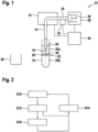
- Fig. 1 schematically shows a laboratory automation device 10, which comprises an automatically movable pipetting arm 12 to which a pipette 14 is attached.
- the pipette tip 16 of the pipette 14 may be lowered into a sample container 18 via the movable pipetting arm 12.
- the container 18 may be a test tube with a centrifuged blood sample.
- the pipetting arm 12 may move the pipette 14 and the pipette tip 16 in three dimensions, may lower the pipette tip 16 into the sample container 18 and may retract the pipette tip 16 therefrom.
- liquid media 20a, 20b are contained, which have a different density and which separate themselves in a vertical direction, for example under gravity or centrifugal forces.
- the two liquid media 20a, 20b are separated by an interface 22.
- the interface 22 may be seen as a layer or plane between the liquid media 20a, 20b. It has to be noted that there is a second interface 24, which is present between the liquid media 20a and the air of the environment.
- the first liquid media 20a may be blood plasma and the second liquid media 20b may contain blood cells, such as red and white blood cells.
- the red and white blood cells also may be separated from each other and the white blood cells may form a small layer 26 between the plasma and the red blood cells. This layer 26 may be seen as a part of the interface 22.
- the two liquid media 20a, 20b may be two unmixable liquids, which are used for liquid-liquid extraction.
- the laboratory automation system 10 furthermore comprises a pump 28, which is connected via a hose 30 with the pipette 14. With the pump 28, a pressure may be applied to the hose 30 and to the pipette 14, which causes the pipette 14 to aspirate or dispense a liquid medium 20a, 20b or any other fluid.
- the pump 28 comprises a plunger 29, which is moved for generating underpressure and overpressure in the hose 30 and the pipette 14.
- a pressure sensor 32 which may be attached to the hose 30 and/or the pipette 14, is adapted for measuring a pressure in the hose 30 and/or the pipette 14.
- a control device 34 of the laboratory automation device10 which may be a part of the laboratory automation device 10 or connected thereto, may control the pipetting arm 12, the pump 28 and may receive a pressure signal from the pressure sensor 32.
- liquid may be aspirated from the sample container 18 with the pipette 14 by generating an underpressure in the pipette 14, wherein the first liquid medium 20a of the two liquid media is aspirated and after the interface 22 and the pipette tip 16 pass each other, the second liquid medium 20b of the two liquid media is aspirated.
- a pressure in the pipette 14 is measured with the pressure sensor 32, while the pipette tip 16 and the interface 22 move with respect to each other and the position of the interface 22 is detected, when a slope of the pressure changes.
- Fig. 1 also shows a further sample container 36 into which the first liquid medium 20a will be dispensed as described below.
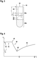
- Fig. 2 shows a flow diagram for aspirating the first liquid medium 20a and for transporting the first liquid medium 20a into the further sample container 36.
- the method may be performed by the laboratory automation device 10 controlled by the control device 34.
- step S10 the pipette tip 16 is moved into the container 18 and lowered into the container 18, until the liquid level 24 being the boundary between the first liquid medium 20a and air is reached.
- the liquid level 24 may be detected with a capacitive method.
- the pipette tip 16 is moved in the sample container 18 along at least a part of a path 38 intersecting the interface 22 between the first liquid medium 20a and the second liquid medium 20b.
- the pipette tip 16 may be moved along a vertical direction, however, more complicated paths 38 are possible, which may have components in a horizontal direction and/or inclined sections.
- step S12 when the pipette tip is immersed in the first liquid 20a, liquid is aspirated from the sample container 18 with the pipette 14 by generating an underpressure in the pipette 14 with the pump 28.
- the first liquid medium 20a is then aspirated, when the pipette tip 16 is above the interface 22, and after passing the interface 22, when the pipette tip 16 is below the interface 22, the second liquid medium 20b is aspirated by the pipette tip 16.
- step S12 the amount of first liquid medium 20a in the pipette 14 is estimated, which may be determined from the volume rate of the pump 28.
- step S14 the method continues in step S14, where the content of the pipette is dispensed into the second sample container 36.
- step S12 the pressure sensor 32 measures a pressure signal 40 (see Fig. 4 ) in the pipette 14, while the pipette tip 16 is moved.
- a pressure signal 40 see Fig. 4
- the method continues in step S16.
- step S14 where the pipette 14 is withdrawn from the sample container 18 and the first liquid medium 20a in the pipette 14 is dispensed into the further sample container 36.
- step S12 where again the pipette tip 16 is lowered into the sample container 18.
- blood samples usually have a volume of 9mL or 6mL, where the plasma content is 53-59%, a usual pipette 14 will be full before reaching the interface 22.
- the air-liquid interface i.e. the level 24, may be detected, for example with a capacitive method.
- the plasma is dispensed into the container 36 and the pipette 14 can aspirate more plasma. This may be repeated until the interface 22 to the red blood cells is reached.
- a post-detection procedure may be performed, when the interface 22 has been detected.
- the pipette 14 may be withdrawn from the sample container 18 and/or an amount of liquid from the pipette 14 may be dispensed such that an aspirated amount of second liquid medium 20b and if desired a fraction of the first liquid medium 20a is discarded.
- the method may continue with dispensing the first liquid medium 20a in the pipette 14 into the further sample container 36 and may stop afterwards. It also may be that the pipette 14 moves back to the first liquid container 18 and aspirates the remaining amount of the first liquid medium 20a with interface detection. This is possible since the position 22 of the interface position is now known.
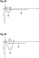
- Fig. 3 the movement path 38 of the pipette tip 16 during step S12 is shown, when liquid is aspirated.
- the pipette tip 16 In a first pass, the pipette tip 16 is moved from a level z 0 , where the liquid level is at the starting time, for a lowering distance I to the level z 2 , where the pipette 14 has been filled up or is filled to its aspiration volume.
- the movement from z 0 to z 2 may be done rather fast and/or with a speed, such that the aspirated liquid medium 20a, 20b is enough for interface detection.
- the movement At z 2 , when no interface 22 has been detected, the movement may be stopped and first liquid medium 20a may be aspirated until the pipette 14 is filled up to the aspiration volume.
- the pipette tip is retracted for a safety distance d from the level z 2 to the level z 1 and that there, the pipette 14 is filled up to the aspiration volume.
- the pipette tip 16 in the sample container 18 may be lowered to a level at which the pipette tip 16 was at an end of a previous detection movement.
- the pipette tip 16 also may be lowered to a level z 1 , which is a safety distance d above the level z 2 at which the previous detection movement was stopped.
- the benefit of the safety distance d will be described with respect to the following figures.
- the retraction safety distance after the distance I is reached may be different from the lowering safety distance, which is used during again lowering the pipette into the container.
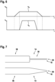
- Fig. 4 shows a diagram with a pressure signal or pressure curve 40, which has been recorded during a movement of the pipette tip 16 through the interface 22.
- the pressure 40 shown in Fig. 4 may be the one as the last detection movement performed in step S12, when in the end, the interface 22 is detected.
- Fig. 4 is an example of a pressure signal 40, which was recorded during aspiration of blood plasma, when entering from the plasma into the erythrocytes.
- the slope of the pressure 40 changes.
- the diagram shows the time t on the horizontal axis and pressure p on the vertical axis.
- the underpressure is generated and in a first time interval 42, the first liquid medium 20a starts to enter the pipette tip 16.
- the pressure 40 varies, since the flow in the pipette tip 16 has not yet stabilized.
- the slope of the pressure 40 is constant.
- the volume rate of the pump 28 has been adjusted to the amount of first liquid medium 20a flowing into the pipette 14.
- the pipette tip 16 enters the second liquid medium 20b, which is more viscous as the first liquid medium 20a and in the following time interval 46, the slope of the pressure 40 changes (it deceases). This slope change is detected by the controller 34, which then stops the pump 28 and the movement of the pipette tip 16. After the stop of the pump 28, the pressure starts to increase again.
- the first time interval 42 it may be beneficial to introduce a waiting time t w after starting the pump 28, before the interface detection 22 becomes active, to ignore the pressure change when the first liquid medium 20 starts to enter into the empty pipette tip 16. Furthermore, it may be beneficial to stop the z-movement of the pipette tip 16 and the pump 28 upon interface detection to avoid aspiration of a large amount of the second liquid medium 20b and to minimize a contamination risk.
- v z is the z-axis speed of the pipette tip 16.
- speed v l of the liquid level should be smaller than the speed v z of the pipette tip 16. It has to be noted that v z may only be the z-component of the speed of the pipette tip 16 and that speed of the pipette tip 16 also may have components in another direction.
- Fig. 5A to 5D show diagrams indicating the z-coordinate respectively the level 50 of the pipette tip 16 and the liquid level 52 in the sample container 18 during lowering and retreating the pipette 14 in the sample container 18 in different scenarios.
- the diagrams all start at time t 0 , where it has been detected that the pipette tip 16 has touched the liquid level 24 in the sample container 18 and the pump 28 is started.
- Fig. 5A and 5B the pipette 16 is lowered into the sample container 18 with a constant speed for the distance I until a time t 1 is reached. During this movement interface detection is performed. In Fig. 5A and 5B no interface is detected.
- the pipette 16 is withdrawn by a safety distance d and stopped there. Then the rest of the aspiration volume is aspirated until a time t 3 . Afterwards, the pipette is completely removed from the sample container 18 and dispensed in the further sample container 36.
- the liquid medium 20a is aspirated with a constant aspiration rate between the times t 0 and t 3 .
- the liquid level 52 drops with a constant rate between these two time points.
- the liquid medium 20a is aspirated with a first aspiration rate during the lowering of the pipette 14 between t 0 and tz.
- This first aspiration rate is lower than a second aspiration rate between t 2 and t 3 , where the rest of the aspiration volume of the liquid medium 20a is aspirated.
- Fig. 5C and 5D show scenarios, where the interface 22 is detected at a time t ⁇ 1 , before the pipette 14 has been moved for the distance I.
- the pipette 14 is then stopped and withdrawn from the sample container 18. After that the aspirated amount of the second liquid medium 20b may be discarded by dispensing a small content of the pipette 14. The remaining content may be dispensed in the further sample container 36. It also may be that then the complete content of the pipette 14 is discarded.
- Fig. 5D after the interface detection at time t ⁇ 1 an amount of the content of the pipette 14 is dispensed until time t ⁇ 2 . This dispensing is done at the level, where the interface has been detected. After that the pipette 14 is withdrawn from the sample container 18 and, for example, may be dispensed into the further sample container 36.
- an aspiration rate of the aspirated liquid medium 20a has been adjusted, such that a movement speed of the liquid level 52 in the sample container 18 is slower than a movement speed of the pipette tip 16.
- aspirationFig 6 shows a diagram with a speed/volume rate v p of the pump 28, which may be proportional to the speed of the plunger 29 and a speed v z of the pipette tip. Both quantities are depicted over time t.
- the pipette tip 16 solely moves when the pump 28 has a constant speed and/or volume rate v p . If the pump 28 is in an acceleration or deceleration phase, then the interface detection may be more difficult and/or not so accurate. It may be that the pipette tip 16 is solely moved, when a pump 28 generating the underpressure operates at a constant volume rate v p . When the pump 28 comprises a plunger 29, the pipette 14 may be solely moved, when the plunger 29 is moved with constant speed v p .
- Fig. 7 schematically shows two tip designs for pipettes 14, which may be used in the laboratory automation device 10, when the method is performed.
- the upper pipette 14 has an elongated nozzle 54 with a diameter along the extension of the nozzle, which varies at least 10% from a mean diameter of the nozzle 54.
- the mean diameter of the nozzle 54 may be smaller than the mean diameter of the rest of the pipette, i.e. the pipette body 56, for example more than 3 times.
- An elongated nozzle 54 may be beneficial in washing dispensing (see description of step S16) the undesired second liquid medium 20b from the pipette tip 16.
- the lower pipette 14 has a conical pipette tip with a small orifice 58, which, for example, may have a diameter of less than 10% of a diameter of the pipette body 56.
- a smaller orifice 58 may allow to have a higher sensitivity and trigger a faster stop when the pipette tip 16 enters into the second liquid medium 20b.
- the upper pipette 14 with the nozzle 54 may have such a small orifice 58.
- second liquid medium 20b there usually is an amount of second liquid medium 20b in the pipette tip 16.
- the amount of second liquid medium 20b may be calculated from the pressure-time curve with the knowledge of the aspiration speed. For better washing of the second liquid medium 20b, for example in a nozzle 54, an additional amount of first liquid medium 20a may be dispensed.
Landscapes
- Life Sciences & Earth Sciences (AREA)
- Physics & Mathematics (AREA)
- Health & Medical Sciences (AREA)
- Chemical & Material Sciences (AREA)
- Analytical Chemistry (AREA)
- Biochemistry (AREA)
- General Health & Medical Sciences (AREA)
- General Physics & Mathematics (AREA)
- Immunology (AREA)
- Pathology (AREA)
- Hydrology & Water Resources (AREA)
- Automatic Analysis And Handling Materials Therefor (AREA)
Claims (15)
- Verfahren zum Ansaugen eines ersten flüssigen Mediums (20a) von zwei flüssigen Medien (20a, 20b) unterschiedlicher Dichte aus einem Probenbehälter (18), wobei das Verfahren umfasst:Absenken einer Pipette (14) der Laborautomatisierungsvorrichtung (10) in den Probenbehälter (18), bis eine Pipettenspitze (16) der Pipette (14) eine Absenkdistanz (L) von der Oberfläche des ersten flüssigen Mediums (20a) in dem Probenbehälter (18) zurückgelegt hat, wobei die Absenkdistanz (1) so gewählt wird, dass die Pipettenspitze (16) mindestens ein Ansaugvolumen in dem Probenbehälter (18) entspricht;Ansaugen von Flüssigkeit aus dem Probenbehälter (18) während des Absenkens der Pipette (14) durch Generieren eines Unterdrucks in der Pipette (14), wobei das erste flüssige Medium (20a) angesaugt wird, und nachdem die Grenzfläche (22) und die Pipettenspitze (16) einander passieren, das zweite flüssige Medium (20b) der zwei flüssigen Medien angesaugt wird;Messen eines Drucks (40) in der Pipette (14) während des Absenkens der Pipette (14) und Detektieren einer Position der Grenzfläche (22), wenn sich eine Steigung (44) des Drucks (40) ändert;dadurch gekennzeichnet, dass:
wenn die Absenkdistanz (1) zurückgelegt wurde und keine Grenzfläche (22) detektiert wird, Ansaugen des Ansaugvolumens aus dem ersten flüssigen Medium (20a) und Abgeben des Ansaugvolumens des ersten flüssigen Mediums (20a) in einen weiteren Probenbehälter (36). - Verfahren nach Anspruch 1,
wenn das Ansaugvolumen des ersten flüssigen Mediums (20a) in den weiteren Probenbehälter (36) abgegeben wurde, Wiederholen von:
Absenken der Pipette (14) um die dem Ansaugvolumen entsprechende Absenkdistanz (1), Detektieren der Grenzfläche (22) und, wenn keine Grenzfläche (22) detektiert wird, Ansaugen des Ansaugvolumens. - Verfahren nach Anspruch 1 oder 2,
wobei, wenn die Absenkdistanz (1) zurückgelegt wurde und keine Grenzfläche (22) detektiert wird, Zurückziehen der Pipette (14) um eine Sicherheitsdistanz (d) vor dem Ansaugen des Ansaugvolumens. - Verfahren nach einem der vorangehenden Ansprüche,
wobei, wenn die Absenkdistanz (1) zurückgelegt wurde und keine Grenzfläche (22) detektiert wird, Stoppen der Pipette (14), bevor das Ansaugvolumen angesaugt wird. - Verfahren nach einem der vorangehenden Ansprüche,
wobei eine erste Ansaugrate während des Absenkens der Pipette (14) um die Absenkdistanz (1) geringer ist als eine zweite Ansaugrate, nachdem die Absenkdistanz (1) zurückgelegt wurde. - Verfahren nach einem der vorangehenden Ansprüche,wobei eine Ansaugrate des angesaugten flüssigen Mediums (20a) so eingestellt wird, dass eine Bewegungsgeschwindigkeit eines Flüssigkeitsniveaus (52) in dem Probenbehälter (18) langsamer ist als eine Bewegungsgeschwindigkeit (vz) der Pipettenspitze (16);wobei eine Bewegungsgeschwindigkeit (vz) der Pipettenspitze (16) mindestens 10 % schneller, insbesondere 2- bis 5-mal schneller als die Bewegungsgeschwindigkeit des Flüssigkeitsniveaus (52) ist.
- Verfahren nach einem der vorangehenden Ansprüche,
wobei die Pipettenspitze (16) nur dann bewegt wird, wenn eine Vorrichtung (28), die den Unterdruck oder den Überdruck generiert, mit einer konstanten Volumenrate arbeitet. - Verfahren nach Anspruch 7,
wobei die Vorrichtung (20) einen Stößel (29) aufweist und die Pipette (14) nur dann bewegt wird, wenn der Stößel (29) mit konstanter Geschwindigkeit bewegt wird. - Verfahren nach einem der vorangehenden Ansprüche,
nach Detektion der Grenzfläche (22), Zurückziehen der Pipette (14) aus dem Probenbehälter (18) und Verwerfen einer Menge an Flüssigkeit aus der Pipette (14), dergestalt, dass eine angesaugte Menge des zweiten flüssigen Mediums (20b) verworfen wird. - Verfahren nach einem der vorangehenden Ansprüche,
nach Detektion der Grenzfläche (22), Stoppen der Pipettenspitze (16) an der detektierten Position und Generieren eines Überdrucks, um eine Menge des zweiten angesaugten flüssigen Mediums (20b) und/oder eine Menge des ersten angesaugten flüssigen Mediums (20a) aus der Pipette (14) abzugeben. - Verfahren nach einem der vorangehenden Ansprüche, umfassend des Weiteren:
nachdem das Ansaugvolumen des ersten flüssigen Mediums (20a) in den weiteren Probenbehälter (36) abgegeben wurde, Absenken der Pipettenspitze (16) in den Probenbehälter (18) auf ein Niveau, auf dem sich die Pipettenspitze (16) an einem Ende einer vorherigen Bewegung befand, bei der eine Grenzflächendetektion durchgeführt wurde, und von diesem Niveau aus, Fortsetzen des Absenkens der Pipette (14) in den Probenbehälter (18), bis die Pipettenspitze (16) die dem Ansaugvolumen entsprechenden Absenkdistanz (1) von der Oberfläche des ersten flüssigen Mediums (20a) aus zurückgelegt hat. - Verfahren nach Anspruch 11,
wobei die Pipettenspitze (16) auf ein Niveau (z1) abgesenkt wird, das eine Sicherheitsdistanz (d) von dem Niveau (z2) entfernt ist, bei dem die vorherige Detektionsbewegung gestoppt wurde. - Computerprogramm zum Ansaugen eines ersten flüssigen Mediums (20a) von zwei flüssigen Medien (20a, 20b) unterschiedlicher Dichte aus einem Probenbehälter (18), wobei das Computerprogramm, wenn es durch einen Prozessor einer Steuervorrichtung (34) einer Laborautomatisierungsvorrichtung (10) ausgeführt wird, dafür ausgelegt ist, die Vorrichtung nach Anspruch 15 zu veranlassen, die Schritte des Verfahrens nach einem der vorangehenden Ansprüche auszuführen.
- Computerlesbares Medium, auf dem ein Computerprogramm nach Anspruch 13 gespeichert ist.
- Laborautomatisierungsvorrichtung (10), umfassend:einen Pipettierarm (12) zum Tragen einer Pipette (14);eine Druckvorrichtung (28) zum Ändern eines Drucks in einem mit der Pipette (14) verbundenen Volumen (30) zum Ansaugen und Abgeben eines flüssigen Mediums (20a, 20b) in der Pipette (14);einen Drucksensor (32) für Druckmessungen in dem mit der Pipette (14) verbundenen Volumen (30);eine Steuervorrichtung (34) zum Steuern der Druckvorrichtung (28) und des Pipettierarms (12) und zum Empfangen eines Drucksignals (40) von dem Drucksensor (32);wobei die Steuervorrichtung (34) dafür ausgelegt ist, das Verfahren nach einem der Ansprüche 1 bis 12 auszuführen.
Priority Applications (4)
| Application Number | Priority Date | Filing Date | Title |
|---|---|---|---|
| EP25154369.0A EP4521120A1 (de) | 2020-12-21 | 2020-12-21 | Iterative flüssigkeitsabsaugung |
| EP20216046.1A EP4016085B1 (de) | 2020-12-21 | 2020-12-21 | Iterative flüssigkeitsabsaugung |
| US17/554,221 US12455293B2 (en) | 2020-12-21 | 2021-12-17 | Iterative liquid aspiration |
| CN202111561539.0A CN114646500A (zh) | 2020-12-21 | 2021-12-20 | 反复液体吸取 |
Applications Claiming Priority (1)
| Application Number | Priority Date | Filing Date | Title |
|---|---|---|---|
| EP20216046.1A EP4016085B1 (de) | 2020-12-21 | 2020-12-21 | Iterative flüssigkeitsabsaugung |
Related Child Applications (1)
| Application Number | Title | Priority Date | Filing Date |
|---|---|---|---|
| EP25154369.0A Division EP4521120A1 (de) | 2020-12-21 | 2020-12-21 | Iterative flüssigkeitsabsaugung |
Publications (2)
| Publication Number | Publication Date |
|---|---|
| EP4016085A1 EP4016085A1 (de) | 2022-06-22 |
| EP4016085B1 true EP4016085B1 (de) | 2025-02-12 |
Family
ID=73856166
Family Applications (2)
| Application Number | Title | Priority Date | Filing Date |
|---|---|---|---|
| EP20216046.1A Active EP4016085B1 (de) | 2020-12-21 | 2020-12-21 | Iterative flüssigkeitsabsaugung |
| EP25154369.0A Pending EP4521120A1 (de) | 2020-12-21 | 2020-12-21 | Iterative flüssigkeitsabsaugung |
Family Applications After (1)
| Application Number | Title | Priority Date | Filing Date |
|---|---|---|---|
| EP25154369.0A Pending EP4521120A1 (de) | 2020-12-21 | 2020-12-21 | Iterative flüssigkeitsabsaugung |
Country Status (3)
| Country | Link |
|---|---|
| US (1) | US12455293B2 (de) |
| EP (2) | EP4016085B1 (de) |
| CN (1) | CN114646500A (de) |
Families Citing this family (5)
| Publication number | Priority date | Publication date | Assignee | Title |
|---|---|---|---|---|
| CN115469108A (zh) * | 2022-06-30 | 2022-12-13 | 深圳市瑞图生物技术有限公司 | 液基样本处理装置及控制方法 |
| EP4386389A1 (de) * | 2022-12-14 | 2024-06-19 | Tecan Trading AG | Bestimmung physikalischer parameter einer flüssigkeit |
| EP4386354A1 (de) * | 2022-12-14 | 2024-06-19 | Tecan Trading AG | Bestimmung physikalischer parameter einer flüssigkeit mit simulation |
| CN116147731B (zh) * | 2023-04-23 | 2023-07-21 | 成都开图医疗系统科技有限公司 | 一种分层液体界面的液位检测方法 |
| CN116183603B (zh) * | 2023-04-24 | 2024-04-12 | 深圳市帝迈生物技术有限公司 | 一种动物排泄物分析仪 |
Family Cites Families (41)
| Publication number | Priority date | Publication date | Assignee | Title |
|---|---|---|---|---|
| US3897343A (en) | 1974-02-27 | 1975-07-29 | Becton Dickinson Co | Plasma separator-hydrostatic pressure type |
| US4696748A (en) | 1984-10-16 | 1987-09-29 | Asahi Medical Co., Ltd. | Plasma separator and a process for preparing the same |
| US5463895A (en) | 1990-11-09 | 1995-11-07 | Abbott Laboratories | Sample pipetting method |
| CH682847A5 (de) | 1991-12-12 | 1993-11-30 | Hamilton Bonaduz Ag | Verfahren und Vorrichtung zum Verdrängen einer heterogenen Mischung. |
| JP3351615B2 (ja) | 1994-03-17 | 2002-12-03 | ソニー株式会社 | 液の境界検出方法と液分離方法 |
| US5529754A (en) | 1994-05-02 | 1996-06-25 | Hoffmann-La Roche Inc. | Apparatus for capacitatively determining the position of a pipetting needle within an automated analyzer |
| US5512247A (en) | 1994-05-02 | 1996-04-30 | Hoffmann-La Roche Inc. | Apparatus for testing pipetting needle linearity in an automated analyzer |
| US6158269A (en) * | 1995-07-13 | 2000-12-12 | Bayer Corporation | Method and apparatus for aspirating and dispensing sample fluids |
| US5750881A (en) * | 1995-07-13 | 1998-05-12 | Chiron Diagnostics Corporation | Method and apparatus for aspirating and dispensing sample fluids |
| US5665601A (en) * | 1996-01-22 | 1997-09-09 | Johnson & Johnson Clinical Diagnostics, Inc. | Avoiding bubble formation while sensing air-liquid interface using pressurized air flow |
| US5753512A (en) * | 1996-11-13 | 1998-05-19 | Johnson & Johnson Clinical Diagnostics, Inc | Determining liquid volumes in cup-like vessels on a rotor having vertical deviations |
| DE10052819B4 (de) * | 2000-10-24 | 2004-02-19 | Fraunhofer-Gesellschaft zur Förderung der angewandten Forschung e.V. | Pipettensystem und Pipettenarray sowie Verfahren zum Befüllen eines Pipettensystems |
| ES2250644T3 (es) | 2001-03-09 | 2006-04-16 | Hamilton Bonaduz Ag | Procedimiento y dispositivo para evaluar un proceso de dosificacion de liquido. |
| DE10148608A1 (de) | 2001-03-09 | 2002-09-12 | Hamilton Bonaduz Ag Bonaduz | Verfahren und Vorrichtung zur Beurteilung eines Flüssigkeitsdosierungsvorgangs |
| WO2006123771A1 (ja) * | 2005-05-19 | 2006-11-23 | Universal Bio Research Co., Ltd. | 分注量検出方法および吸液モニタ型分注装置 |
| EP1745851B1 (de) * | 2005-07-22 | 2015-02-25 | Tecan Trading AG | Verfahren, Vorrichtung und Computerprogrammprodukt zum Klassifizieren einer Flüssigkeit |
| US8012766B2 (en) * | 2005-08-01 | 2011-09-06 | Ortho-Clinical Diagnostics, Inc. | Prediction of aspirated volume of a liquid |
| WO2007126908A2 (en) * | 2006-03-31 | 2007-11-08 | Artel, Inc. | Air displacement liquid delivery system and related method |
| JP4538478B2 (ja) * | 2007-08-31 | 2010-09-08 | 株式会社日立ハイテクノロジーズ | 自動分析装置 |
| JP5199785B2 (ja) | 2008-08-20 | 2013-05-15 | ベックマン コールター, インコーポレイテッド | 血液サンプル検出方法、血液サンプル分注方法、血液サンプル分析方法、分注装置および血液サンプル種類検出方法 |
| JP5575410B2 (ja) * | 2009-02-16 | 2014-08-20 | 株式会社東芝 | 自動分析装置 |
| JP2010216876A (ja) | 2009-03-13 | 2010-09-30 | Beckman Coulter Inc | 分析装置および分注プローブ洗浄方法 |
| WO2011027851A1 (ja) * | 2009-09-07 | 2011-03-10 | コニカミノルタホールディングス株式会社 | マイクロチップ送液システム、検体検出装置、及びマイクロチップ送液システムの送液方法 |
| WO2011107472A1 (en) * | 2010-03-01 | 2011-09-09 | Novozymes A/S | Viscosity pressure assay |
| CN103282781B (zh) * | 2010-11-23 | 2015-10-14 | 安德鲁联合有限公司 | 用于移液管的可编程操纵的设备和方法 |
| CA2766735C (en) * | 2011-02-07 | 2020-06-02 | Ortho-Clinical Diagnostics, Inc. | Determining conditions in centrifuged blood using measured pressure |
| US10105697B2 (en) * | 2014-08-15 | 2018-10-23 | Biomerieux, Inc. | Methods, systems, and computer program products for detecting a surface using a pipette and/or positioning a pipette |
| EP3081942A1 (de) * | 2015-04-17 | 2016-10-19 | Roche Diagniostics GmbH | Druckübertragungsflüssigkeit für zellanalysator, zellanalysator und verfahren zur analyse einer flüssigen zellprobe |
| WO2016181466A1 (ja) * | 2015-05-11 | 2016-11-17 | 株式会社安川電機 | 分注システム、コントローラ及び制御方法 |
| US10502752B2 (en) * | 2015-11-13 | 2019-12-10 | Konica Minolta, Inc. | Reaction method including pipette height detection and correction |
| US10379131B2 (en) * | 2015-11-18 | 2019-08-13 | Elbit Systems Of America/Kmc Systems, Inc. | Systems and methods for detecting a liquid level |
| TWI604182B (zh) * | 2016-04-26 | 2017-11-01 | 諾貝爾生物有限公司 | 取樣組件及其方法 |
| DE102016005077A1 (de) * | 2016-04-27 | 2017-11-02 | Fraunhofer-Gesellschaft zur Förderung der angewandten Forschung e.V. | Probenbehälter für eine kryokonservierte biologische Probe, Verfahren zur Herstellung des Probenbehälters, Verfahren zur Temperaturüberwachung einer kryokonservierten Probe |
| CH712764A2 (de) * | 2016-07-22 | 2018-01-31 | Tecan Trading Ag | Pipettenspitze aufweisend eine Volumenmesselektrode sowie Verfahren zu deren Herstellung und Pipettiervorrichtung. |
| WO2019060716A1 (en) * | 2017-09-25 | 2019-03-28 | Freenome Holdings, Inc. | SAMPLE EXTRACTION METHODS AND SYSTEMS |
| US20250170568A1 (en) * | 2017-12-28 | 2025-05-29 | Formulatrix International Holding Ltd. | Pipette tip for and method of automatically maintaining pipette tip depth in a fluid during a fluid transfer operation |
| JP7339260B2 (ja) * | 2017-12-28 | 2023-09-05 | フォーミュラトリクス・インターナショナル・ホールディング・リミテッド | 液体内のピペットチップの深さを自動的に保つためのピペットチップ及び方法 |
| CN207751770U (zh) | 2017-12-30 | 2018-08-21 | 广州阳普医疗科技股份有限公司 | 一种筛选循环肿瘤细胞的采血装置 |
| CN107917835A (zh) | 2017-12-30 | 2018-04-17 | 广州阳普医疗科技股份有限公司 | 一种筛选循环肿瘤细胞的采血装置 |
| JP7177596B2 (ja) * | 2018-02-27 | 2022-11-24 | シスメックス株式会社 | 検体測定装置及び検体測定方法 |
| EP3765197B1 (de) * | 2018-04-06 | 2025-08-06 | Muscle Lab Canada Inc. | Integrierte pipettiervorrichtung |
-
2020
- 2020-12-21 EP EP20216046.1A patent/EP4016085B1/de active Active
- 2020-12-21 EP EP25154369.0A patent/EP4521120A1/de active Pending
-
2021
- 2021-12-17 US US17/554,221 patent/US12455293B2/en active Active
- 2021-12-20 CN CN202111561539.0A patent/CN114646500A/zh active Pending
Also Published As
| Publication number | Publication date |
|---|---|
| EP4521120A1 (de) | 2025-03-12 |
| US20220196696A1 (en) | 2022-06-23 |
| CN114646500A (zh) | 2022-06-21 |
| US12455293B2 (en) | 2025-10-28 |
| EP4016085A1 (de) | 2022-06-22 |
Similar Documents
| Publication | Publication Date | Title |
|---|---|---|
| EP4016085B1 (de) | Iterative flüssigkeitsabsaugung | |
| JP7611967B2 (ja) | 自動顕微鏡血球分析 | |
| EP1210575B1 (de) | Verbessertes verfahren und vorrichtung zum ansaugen und verteilen von flüssigkeiten | |
| JP6647288B2 (ja) | 自動分析装置及び方法 | |
| JP4938082B2 (ja) | 洗浄装置、吸引ノズルの詰り検知方法及び自動分析装置 | |
| JP5123390B2 (ja) | 臨床サンプリング・ピペットにおける詰まりの検出 | |
| EP3065797B1 (de) | Verfahren und vorrichtung zur bestimmung der aspirations- und/oder ausgabemenge und/oder pipettenpositionierung | |
| US9052300B2 (en) | Methods, systems, and apparatus to determine a clot carryout condition upon probe retraction during sample aspiration and dispensing | |
| JP2003533701A (ja) | 流体移動の完全性を確かめる方法 | |
| US7661326B2 (en) | Apparatus for aspirating and dispensing liquids in an automated analyzer | |
| EP3058352B1 (de) | Verfahren und vorrichtung zur messung eines saugdrucks | |
| JP2018096915A (ja) | 自動分析装置 | |
| JP7200357B2 (ja) | 実験器具の動作方法 | |
| US20230408541A1 (en) | Liquid interface estimation for liquid aspiration | |
| EP4190451A1 (de) | Pipettenspitze und pipettensystem zur kapillarblutentnahme | |
| CN112881739B (zh) | 加样方法及其装置、计算机存储介质、样本分析方法及其装置 | |
| JPS61254833A (ja) | 液定量取出し装置 | |
| JP2015031586A (ja) | 分析装置及び液体吸引装置 | |
| WO2021215068A1 (ja) | 分注装置、自動分析装置、分注方法 | |
| JP2008298494A (ja) | 分注装置 | |
| JPH02243960A (ja) | 分析装置の分注器操作方式 | |
| JP2012021892A (ja) | 自動分析装置及び分注方法 | |
| JP3317530B2 (ja) | 分注方法と分注装置 | |
| EP3842768A1 (de) | Vorrichtung zur feststellung des flüssigkeitsstandes | |
| WO2009061748A1 (en) | Waterspout aspiration system |
Legal Events
| Date | Code | Title | Description |
|---|---|---|---|
| PUAI | Public reference made under article 153(3) epc to a published international application that has entered the european phase |
Free format text: ORIGINAL CODE: 0009012 |
|
| STAA | Information on the status of an ep patent application or granted ep patent |
Free format text: STATUS: THE APPLICATION HAS BEEN PUBLISHED |
|
| AK | Designated contracting states |
Kind code of ref document: A1 Designated state(s): AL AT BE BG CH CY CZ DE DK EE ES FI FR GB GR HR HU IE IS IT LI LT LU LV MC MK MT NL NO PL PT RO RS SE SI SK SM TR |
|
| STAA | Information on the status of an ep patent application or granted ep patent |
Free format text: STATUS: REQUEST FOR EXAMINATION WAS MADE |
|
| 17P | Request for examination filed |
Effective date: 20221208 |
|
| RBV | Designated contracting states (corrected) |
Designated state(s): AL AT BE BG CH CY CZ DE DK EE ES FI FR GB GR HR HU IE IS IT LI LT LU LV MC MK MT NL NO PL PT RO RS SE SI SK SM TR |
|
| GRAP | Despatch of communication of intention to grant a patent |
Free format text: ORIGINAL CODE: EPIDOSNIGR1 |
|
| STAA | Information on the status of an ep patent application or granted ep patent |
Free format text: STATUS: GRANT OF PATENT IS INTENDED |
|
| RIC1 | Information provided on ipc code assigned before grant |
Ipc: B01L 3/02 20060101ALI20240905BHEP Ipc: G01N 35/10 20060101AFI20240905BHEP |
|
| INTG | Intention to grant announced |
Effective date: 20240913 |
|
| GRAS | Grant fee paid |
Free format text: ORIGINAL CODE: EPIDOSNIGR3 |
|
| GRAA | (expected) grant |
Free format text: ORIGINAL CODE: 0009210 |
|
| STAA | Information on the status of an ep patent application or granted ep patent |
Free format text: STATUS: THE PATENT HAS BEEN GRANTED |
|
| AK | Designated contracting states |
Kind code of ref document: B1 Designated state(s): AL AT BE BG CH CY CZ DE DK EE ES FI FR GB GR HR HU IE IS IT LI LT LU LV MC MK MT NL NO PL PT RO RS SE SI SK SM TR |
|
| REG | Reference to a national code |
Ref country code: GB Ref legal event code: FG4D |
|
| REG | Reference to a national code |
Ref country code: CH Ref legal event code: EP |
|
| REG | Reference to a national code |
Ref country code: DE Ref legal event code: R096 Ref document number: 602020045863 Country of ref document: DE |
|
| REG | Reference to a national code |
Ref country code: IE Ref legal event code: FG4D |
|
| P01 | Opt-out of the competence of the unified patent court (upc) registered |
Free format text: CASE NUMBER: APP_7380/2025 Effective date: 20250213 |
|
| REG | Reference to a national code |
Ref country code: NL Ref legal event code: MP Effective date: 20250212 |
|
| PG25 | Lapsed in a contracting state [announced via postgrant information from national office to epo] |
Ref country code: RS Free format text: LAPSE BECAUSE OF FAILURE TO SUBMIT A TRANSLATION OF THE DESCRIPTION OR TO PAY THE FEE WITHIN THE PRESCRIBED TIME-LIMIT Effective date: 20250512 |
|
| PG25 | Lapsed in a contracting state [announced via postgrant information from national office to epo] |
Ref country code: FI Free format text: LAPSE BECAUSE OF FAILURE TO SUBMIT A TRANSLATION OF THE DESCRIPTION OR TO PAY THE FEE WITHIN THE PRESCRIBED TIME-LIMIT Effective date: 20250212 |
|
| PG25 | Lapsed in a contracting state [announced via postgrant information from national office to epo] |
Ref country code: PL Free format text: LAPSE BECAUSE OF FAILURE TO SUBMIT A TRANSLATION OF THE DESCRIPTION OR TO PAY THE FEE WITHIN THE PRESCRIBED TIME-LIMIT Effective date: 20250212 |
|
| PG25 | Lapsed in a contracting state [announced via postgrant information from national office to epo] |
Ref country code: ES Free format text: LAPSE BECAUSE OF FAILURE TO SUBMIT A TRANSLATION OF THE DESCRIPTION OR TO PAY THE FEE WITHIN THE PRESCRIBED TIME-LIMIT Effective date: 20250212 |
|
| REG | Reference to a national code |
Ref country code: LT Ref legal event code: MG9D |
|
| PG25 | Lapsed in a contracting state [announced via postgrant information from national office to epo] |
Ref country code: NO Free format text: LAPSE BECAUSE OF FAILURE TO SUBMIT A TRANSLATION OF THE DESCRIPTION OR TO PAY THE FEE WITHIN THE PRESCRIBED TIME-LIMIT Effective date: 20250512 Ref country code: IS Free format text: LAPSE BECAUSE OF FAILURE TO SUBMIT A TRANSLATION OF THE DESCRIPTION OR TO PAY THE FEE WITHIN THE PRESCRIBED TIME-LIMIT Effective date: 20250612 |
|
| PG25 | Lapsed in a contracting state [announced via postgrant information from national office to epo] |
Ref country code: NL Free format text: LAPSE BECAUSE OF FAILURE TO SUBMIT A TRANSLATION OF THE DESCRIPTION OR TO PAY THE FEE WITHIN THE PRESCRIBED TIME-LIMIT Effective date: 20250212 |
|
| PG25 | Lapsed in a contracting state [announced via postgrant information from national office to epo] |
Ref country code: HR Free format text: LAPSE BECAUSE OF FAILURE TO SUBMIT A TRANSLATION OF THE DESCRIPTION OR TO PAY THE FEE WITHIN THE PRESCRIBED TIME-LIMIT Effective date: 20250212 |
|
| PG25 | Lapsed in a contracting state [announced via postgrant information from national office to epo] |
Ref country code: PT Free format text: LAPSE BECAUSE OF FAILURE TO SUBMIT A TRANSLATION OF THE DESCRIPTION OR TO PAY THE FEE WITHIN THE PRESCRIBED TIME-LIMIT Effective date: 20250612 Ref country code: LV Free format text: LAPSE BECAUSE OF FAILURE TO SUBMIT A TRANSLATION OF THE DESCRIPTION OR TO PAY THE FEE WITHIN THE PRESCRIBED TIME-LIMIT Effective date: 20250212 |
|
| PG25 | Lapsed in a contracting state [announced via postgrant information from national office to epo] |
Ref country code: GR Free format text: LAPSE BECAUSE OF FAILURE TO SUBMIT A TRANSLATION OF THE DESCRIPTION OR TO PAY THE FEE WITHIN THE PRESCRIBED TIME-LIMIT Effective date: 20250513 Ref country code: BG Free format text: LAPSE BECAUSE OF FAILURE TO SUBMIT A TRANSLATION OF THE DESCRIPTION OR TO PAY THE FEE WITHIN THE PRESCRIBED TIME-LIMIT Effective date: 20250212 |
|
| REG | Reference to a national code |
Ref country code: AT Ref legal event code: MK05 Ref document number: 1766490 Country of ref document: AT Kind code of ref document: T Effective date: 20250212 |
|
| PG25 | Lapsed in a contracting state [announced via postgrant information from national office to epo] |
Ref country code: SE Free format text: LAPSE BECAUSE OF FAILURE TO SUBMIT A TRANSLATION OF THE DESCRIPTION OR TO PAY THE FEE WITHIN THE PRESCRIBED TIME-LIMIT Effective date: 20250212 |
|
| PG25 | Lapsed in a contracting state [announced via postgrant information from national office to epo] |
Ref country code: SM Free format text: LAPSE BECAUSE OF FAILURE TO SUBMIT A TRANSLATION OF THE DESCRIPTION OR TO PAY THE FEE WITHIN THE PRESCRIBED TIME-LIMIT Effective date: 20250212 |
|
| PG25 | Lapsed in a contracting state [announced via postgrant information from national office to epo] |
Ref country code: DK Free format text: LAPSE BECAUSE OF FAILURE TO SUBMIT A TRANSLATION OF THE DESCRIPTION OR TO PAY THE FEE WITHIN THE PRESCRIBED TIME-LIMIT Effective date: 20250212 |
|
| PG25 | Lapsed in a contracting state [announced via postgrant information from national office to epo] |
Ref country code: IT Free format text: LAPSE BECAUSE OF FAILURE TO SUBMIT A TRANSLATION OF THE DESCRIPTION OR TO PAY THE FEE WITHIN THE PRESCRIBED TIME-LIMIT Effective date: 20250212 |
|
| PG25 | Lapsed in a contracting state [announced via postgrant information from national office to epo] |
Ref country code: AT Free format text: LAPSE BECAUSE OF FAILURE TO SUBMIT A TRANSLATION OF THE DESCRIPTION OR TO PAY THE FEE WITHIN THE PRESCRIBED TIME-LIMIT Effective date: 20250212 |
|
| PG25 | Lapsed in a contracting state [announced via postgrant information from national office to epo] |
Ref country code: CZ Free format text: LAPSE BECAUSE OF FAILURE TO SUBMIT A TRANSLATION OF THE DESCRIPTION OR TO PAY THE FEE WITHIN THE PRESCRIBED TIME-LIMIT Effective date: 20250212 Ref country code: EE Free format text: LAPSE BECAUSE OF FAILURE TO SUBMIT A TRANSLATION OF THE DESCRIPTION OR TO PAY THE FEE WITHIN THE PRESCRIBED TIME-LIMIT Effective date: 20250212 |
|
| PG25 | Lapsed in a contracting state [announced via postgrant information from national office to epo] |
Ref country code: RO Free format text: LAPSE BECAUSE OF FAILURE TO SUBMIT A TRANSLATION OF THE DESCRIPTION OR TO PAY THE FEE WITHIN THE PRESCRIBED TIME-LIMIT Effective date: 20250212 |
|
| PG25 | Lapsed in a contracting state [announced via postgrant information from national office to epo] |
Ref country code: SK Free format text: LAPSE BECAUSE OF FAILURE TO SUBMIT A TRANSLATION OF THE DESCRIPTION OR TO PAY THE FEE WITHIN THE PRESCRIBED TIME-LIMIT Effective date: 20250212 |