EP3065797B1 - Verfahren und vorrichtung zur bestimmung der aspirations- und/oder ausgabemenge und/oder pipettenpositionierung - Google Patents
Verfahren und vorrichtung zur bestimmung der aspirations- und/oder ausgabemenge und/oder pipettenpositionierung Download PDFInfo
- Publication number
- EP3065797B1 EP3065797B1 EP14858935.1A EP14858935A EP3065797B1 EP 3065797 B1 EP3065797 B1 EP 3065797B1 EP 14858935 A EP14858935 A EP 14858935A EP 3065797 B1 EP3065797 B1 EP 3065797B1
- Authority
- EP
- European Patent Office
- Prior art keywords
- bio
- image
- aspiration
- liquid container
- liquid
- Prior art date
- Legal status (The legal status is an assumption and is not a legal conclusion. Google has not performed a legal analysis and makes no representation as to the accuracy of the status listed.)
- Active
Links
Images


Classifications
-
- G—PHYSICS
- G01—MEASURING; TESTING
- G01N—INVESTIGATING OR ANALYSING MATERIALS BY DETERMINING THEIR CHEMICAL OR PHYSICAL PROPERTIES
- G01N35/00—Automatic analysis not limited to methods or materials provided for in any single one of groups G01N1/00 - G01N33/00; Handling materials therefor
- G01N35/10—Devices for transferring samples or any liquids to, in, or from, the analysis apparatus, e.g. suction devices, injection devices
- G01N35/1009—Characterised by arrangements for controlling the aspiration or dispense of liquids
- G01N35/1016—Control of the volume dispensed or introduced
-
- B—PERFORMING OPERATIONS; TRANSPORTING
- B01—PHYSICAL OR CHEMICAL PROCESSES OR APPARATUS IN GENERAL
- B01L—CHEMICAL OR PHYSICAL LABORATORY APPARATUS FOR GENERAL USE
- B01L3/00—Containers or dishes for laboratory use, e.g. laboratory glassware; Droppers
- B01L3/02—Burettes; Pipettes
- B01L3/021—Pipettes, i.e. with only one conduit for withdrawing and redistributing liquids
- B01L3/0217—Pipettes, i.e. with only one conduit for withdrawing and redistributing liquids of the plunger pump type
- B01L3/022—Capillary pipettes, i.e. having very small bore
-
- G—PHYSICS
- G01—MEASURING; TESTING
- G01F—MEASURING VOLUME, VOLUME FLOW, MASS FLOW OR LIQUID LEVEL; METERING BY VOLUME
- G01F23/00—Indicating or measuring liquid level or level of fluent solid material, e.g. indicating in terms of volume or indicating by means of an alarm
- G01F23/22—Indicating or measuring liquid level or level of fluent solid material, e.g. indicating in terms of volume or indicating by means of an alarm by measuring physical variables, other than linear dimensions, pressure or weight, dependent on the level to be measured, e.g. by difference of heat transfer of steam or water
- G01F23/28—Indicating or measuring liquid level or level of fluent solid material, e.g. indicating in terms of volume or indicating by means of an alarm by measuring physical variables, other than linear dimensions, pressure or weight, dependent on the level to be measured, e.g. by difference of heat transfer of steam or water by measuring the variations of parameters of electromagnetic or acoustic waves applied directly to the liquid or fluent solid material
- G01F23/284—Electromagnetic waves
- G01F23/292—Light, e.g. infrared or ultraviolet
-
- G—PHYSICS
- G01—MEASURING; TESTING
- G01N—INVESTIGATING OR ANALYSING MATERIALS BY DETERMINING THEIR CHEMICAL OR PHYSICAL PROPERTIES
- G01N35/00—Automatic analysis not limited to methods or materials provided for in any single one of groups G01N1/00 - G01N33/00; Handling materials therefor
- G01N35/00584—Control arrangements for automatic analysers
- G01N35/00722—Communications; Identification
- G01N35/00732—Identification of carriers, materials or components in automatic analysers
-
- G—PHYSICS
- G01—MEASURING; TESTING
- G01N—INVESTIGATING OR ANALYSING MATERIALS BY DETERMINING THEIR CHEMICAL OR PHYSICAL PROPERTIES
- G01N35/00—Automatic analysis not limited to methods or materials provided for in any single one of groups G01N1/00 - G01N33/00; Handling materials therefor
- G01N35/0099—Automatic analysis not limited to methods or materials provided for in any single one of groups G01N1/00 - G01N33/00; Handling materials therefor comprising robots or similar manipulators
-
- G—PHYSICS
- G01—MEASURING; TESTING
- G01N—INVESTIGATING OR ANALYSING MATERIALS BY DETERMINING THEIR CHEMICAL OR PHYSICAL PROPERTIES
- G01N35/00—Automatic analysis not limited to methods or materials provided for in any single one of groups G01N1/00 - G01N33/00; Handling materials therefor
- G01N35/10—Devices for transferring samples or any liquids to, in, or from, the analysis apparatus, e.g. suction devices, injection devices
- G01N35/1009—Characterised by arrangements for controlling the aspiration or dispense of liquids
- G01N35/1011—Control of the position or alignment of the transfer device
-
- A—HUMAN NECESSITIES
- A61—MEDICAL OR VETERINARY SCIENCE; HYGIENE
- A61M—DEVICES FOR INTRODUCING MEDIA INTO, OR ONTO, THE BODY; DEVICES FOR TRANSDUCING BODY MEDIA OR FOR TAKING MEDIA FROM THE BODY; DEVICES FOR PRODUCING OR ENDING SLEEP OR STUPOR
- A61M2205/00—General characteristics of the apparatus
- A61M2205/33—Controlling, regulating or measuring
- A61M2205/3306—Optical measuring means
-
- A—HUMAN NECESSITIES
- A61—MEDICAL OR VETERINARY SCIENCE; HYGIENE
- A61M—DEVICES FOR INTRODUCING MEDIA INTO, OR ONTO, THE BODY; DEVICES FOR TRANSDUCING BODY MEDIA OR FOR TAKING MEDIA FROM THE BODY; DEVICES FOR PRODUCING OR ENDING SLEEP OR STUPOR
- A61M2205/00—General characteristics of the apparatus
- A61M2205/33—Controlling, regulating or measuring
- A61M2205/3379—Masses, volumes, levels of fluids in reservoirs, flow rates
- A61M2205/3389—Continuous level detection
-
- A—HUMAN NECESSITIES
- A61—MEDICAL OR VETERINARY SCIENCE; HYGIENE
- A61M—DEVICES FOR INTRODUCING MEDIA INTO, OR ONTO, THE BODY; DEVICES FOR TRANSDUCING BODY MEDIA OR FOR TAKING MEDIA FROM THE BODY; DEVICES FOR PRODUCING OR ENDING SLEEP OR STUPOR
- A61M5/00—Devices for bringing media into the body in a subcutaneous, intra-vascular or intramuscular way; Accessories therefor, e.g. filling or cleaning devices, arm-rests
- A61M5/178—Syringes
- A61M5/31—Details
- A61M5/315—Pistons; Piston-rods; Guiding, blocking or restricting the movement of the rod or piston; Appliances on the rod for facilitating dosing ; Dosing mechanisms
- A61M5/31565—Administration mechanisms, i.e. constructional features, modes of administering a dose
- A61M5/31566—Means improving security or handling thereof
- A61M5/31568—Means keeping track of the total dose administered, e.g. since the cartridge was inserted
-
- B—PERFORMING OPERATIONS; TRANSPORTING
- B01—PHYSICAL OR CHEMICAL PROCESSES OR APPARATUS IN GENERAL
- B01L—CHEMICAL OR PHYSICAL LABORATORY APPARATUS FOR GENERAL USE
- B01L2200/00—Solutions for specific problems relating to chemical or physical laboratory apparatus
- B01L2200/14—Process control and prevention of errors
- B01L2200/143—Quality control, feedback systems
-
- B—PERFORMING OPERATIONS; TRANSPORTING
- B01—PHYSICAL OR CHEMICAL PROCESSES OR APPARATUS IN GENERAL
- B01L—CHEMICAL OR PHYSICAL LABORATORY APPARATUS FOR GENERAL USE
- B01L2400/00—Moving or stopping fluids
- B01L2400/04—Moving fluids with specific forces or mechanical means
- B01L2400/0475—Moving fluids with specific forces or mechanical means specific mechanical means and fluid pressure
- B01L2400/0478—Moving fluids with specific forces or mechanical means specific mechanical means and fluid pressure pistons
-
- G—PHYSICS
- G01—MEASURING; TESTING
- G01B—MEASURING LENGTH, THICKNESS OR SIMILAR LINEAR DIMENSIONS; MEASURING ANGLES; MEASURING AREAS; MEASURING IRREGULARITIES OF SURFACES OR CONTOURS
- G01B11/00—Measuring arrangements characterised by the use of optical techniques
Definitions
- the present invention relates generally to diagnostic instruments and methods of operation thereof.
- the patient specimen may include a serum or plasma portion (obtained from whole blood by centrifugation).
- an anticoagulant such as citrate or heparin may be added to the patient specimen.
- the open sample container e.g., sample tube
- a support article such as a sample rack.
- the sample rack may be accessible by a pipette of an aspirating system that may extract bio-liquid from the sample container and combine the bio-liquid with one or more reagents and possibly a diluent in a reaction container (e.g., cuvette or cup). After incubation or reaction, analytical measurements may then be performed, using, for example, photometric or fluorometric readings, or the like. The measurements allow determination of values from which an amount of analyte or other substance related to the health of the patient may be determined using well-known techniques.
- a diagnostic device includes a transfer apparatus including a first support article adapted to receive a first bio-liquid container, a second support article adapted to receive a second bio-liquid container, an image capture apparatus located adjacent to one or more of: the first support article and operable to capture one or more images of the bio-liquid container at one or more points in time during a bio-liquid aspiration, the second support article and operable to capture one or more images of the second bio-liquid container at one or more points in time during a bio-liquid dispense, the second support article and operable to capture one or more images of the second bio-liquid container at one or more points in time during a reagent dispense, and the second support article and operable to capture one or more images of the second bio-liquid container after all subcomponent additions, and an image processor operable to process the images to determine at least one selected from a group of: an aspiration height or aspiration volume, a dispense height or dispense volume, an overall height or
- Accurate measurement of the correct volume of liquids and other assay components is desirable in laboratory diagnostic instruments (e.g., clinical analyzers and immunoassay instruments).
- laboratory diagnostic instruments e.g., clinical analyzers and immunoassay instruments.
- additions of amounts of liquid reagent, solid or semisolid reagents, specimen, and diluent (hereinafter "assay subcomponents") be relatively tightly controlled.
- a pipetting operation can be one component of a laboratory diagnostics instrument.
- Substantial errors in assay results may be due to incorrect aspiration and/or dispensing of an amount (volume) of specimen, liquid, semisolid or solid reagent, or even diluent.
- an accuracy of liquid aspirated/dispensed by a pipetting operation may be influenced by any number of factors, such as properties of the aspirated or dispensed liquid, environment, temperature, and humidity. In some cases, even a minor error in measurement of aspirated and/or dispensed volume can have a substantial or strong influence on the accuracy of the test result (e.g., assay result).
- the captured images can be processed by a computing algorithm of an image processor to determine and/or verify various height and/or volume changes due to the aspiration or dispensing of various assay components. Accordingly, the transfer apparatus may verify the accuracy of the dispensed specimen, diluent liquid, reagent, final volume, right mix of reagents, or the like.
- the action recorded (e.g., captured images) by the image capture device and processed by the image processor can determine, in some embodiments, if a standard operating procedure has been properly carried out. For example, fault detection in the execution of pipetting actions, such as immersion and immersion depth of the pipette, aspiration volume, dispense volume, or the like may be carried out. Even sporadic, hard-to-catch errors can be captured by processing one or more images/videos captured by the image capture device. Furthermore, these captured images and/or videos can be archived in a suitable memory to serve as undeniable proof that a correct operating procedure was followed for a particular test.
- an image capture device such as an on-board camera (e.g., digital camera or the like) can be used for capturing one or more images at times during an aspiration, such as: before commencing aspiration, during aspiration, and/or after aspiration.
- an image taken before aspiration can be used for determining the quality and consistency of a pipette or carrying vessel (cuvette). For example, a flaw in the pipette or pipette tip may be determined. Analyzing the captured image of the container vessel further ensures result accuracy.
- an image taken during aspiration can be used for tip immersion depth analysis.
- Increased immersion depth may result in additional liquid or even red blood cells or coagulant being drawn into the pipette.
- Decreased immersion depth may result in air bubbles.
- gross increases in immersion depth may result in the pipette touching the sample container bottom and effectively reduce the aspirated volume. All of this information can be processed by the image processor using the details provided by the images captured by an image capture device, such as an on-board camera.
- an image taken after aspiration can be used to determine a volume of liquid that has been aspirated. This may be accomplished by comparing a liquid height within the bio-liquid container before and after the aspiration, possibly coupled with determining a size of the bio-liquid container, if different sized containers are used. Furthermore, the captured images can be used for analyzing a color of the aspirated liquid, and measuring a height location of an upper or lower meniscus in the bio-liquid container as desired. The ability to measure and/or verify the proper volume (aspiration and/or dispense) may improve an accuracy of the assay result.
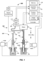
- FIG. 1 illustrates a diagnostic device 100 including a transfer apparatus 101, which in one aspect is capable of automatically determining a characteristic of a first bio-liquid container 108 (e.g., test tube or blood collection tube - see FIG. 1 ) such as a diameter and/or height thereof, and/or a characteristic of a bio-liquid specimen 108S contained therein, and in particular, a change in amount (e.g., height or volume) contained in the first bio-liquid container 108 before and after aspiration.
- the transfer apparatus 101 may be capable of measuring and/or verifying a height or volume of a liquid, solid, or semisolid reagent, diluent, and/or specimen, or combination thereof that is contained in a second bio-liquid container 120, for example.
- the first and second bio-liquid containers 108, 120 may be any generally clear, transparent, translucent or other suitable container may be used, such as a sample cup, cuvette, or other clear glass or plastic container.
- the first bio-liquid container 108 is a blood collection tube
- the second bio-liquid container 120 is a cuvette.
- the diagnostic device 100 includes a first support article 103, such as a sample rack that is adapted to receive the first bio-liquid container 108 containing a bio-liquid specimen 108S and possibly another material, such as a red blood cell (RBC) portion 108R.
- a second support article 105 such as an incubation member (e.g., incubation ring) may be configured and adapted to receive the second bio-liquid container 120 (e.g., a cuvette).
- An image capture apparatus may be positioned adjacent to one or more of the components of the diagnostic device 100 (e.g., at the sides thereof).
- a first image capture device 109A may be located adjacent to the first support article 103 (e.g., at a side thereof).
- a second image capture device 109B may be located adjacent to the second support article 105 (e.g., at a side thereof).
- the location of the first support article 103 and the second support article 105 may be at aspiration and dispense stations, respectively.
- Other image capture devices may be positioned and focused on other areas within the diagnostic device 100.
- the image capture devices may be a suitable digital camera.
- a suitable digital camera is a model Dragonfly2 (DR2) available from Point Grey Research. Other digital cameras or types of image capture devices may be used.
- An image processor 112 may receive the one or more captured images from the image capture devices 109A, 109B and process the images according to a processing scheme or algorithm.
- the image processor 112 may be any suitable computing device that is capable of performing an analysis of the captured digital images.
- the image processor 112 may be a computer having a suitable processor such as a microprocessor-based central processing unit (CPU) and memory and may perform an analysis of an aspiration of the bio-liquid specimen 108S in the first bio-liquid container 108 as it resides in the first support article 103.
- the image processor 112 is adapted to analyze the two or more images in some embodiments. The two or more images may be sequentially obtained and analyzed to obtain a change in volume, as will be apparent from the following.
- An illumination source (not shown) may be used to locally illuminate the first bio-liquid container 108 at times during the aspiration.
- the illumination source may be one or more LED lights, for example. Other types of lighting may be used. Similar lighting may be provided at the second support article 105.
- the transfer apparatus 101 may include an aspiration apparatus 106 as illustrated.
- the aspiration apparatus 106 may include any suitable robot 102 and a pipette 104 (sometimes referred to as a sample probe) adapted to aspirate the bio-liquid specimen 108S. Bio-liquid specimen 108S may also be dispensed by the aspiration apparatus 106.
- the robot 102 may be configured and adapted to carry out motion of the pipette 104 in one or more coordinate directions, such as X, Y (into and out of the paper), and/or Z. However, typically, the robot 102 may move the pipette 104 in the X and Z directions only.
- the robot 102 may be any suitable robot adapted to move the pipette 104, and may include one or more robot components (e.g., robot arm(s), link(s), boom(s), frame (s), or the like) to which the pipette 104 may be mounted to accomplish motion thereof.
- the robot 102 may be operable to descend and ascend the pipette 104 into and out of the first bio-liquid container 108 containing a bio-liquid specimen 108S, so that at least some may be aspirated.
- the bio-liquid specimen 108S may be blood serum, plasma, cerebral liquid, spinal liquid, interstitial liquid, urine, or the like. Other liquids may be aspirated.
- the robot 102 may be suitably actuated under the control of a position control 114 of a controller 116 to impart the desired motions to the pipette 104 in one dimension, two dimensions, or three dimensions.
- the robot 102 may be operated by signals from the position control 114 to move the pipette 104 from the first bio-liquid container 108 to the second bio-liquid container 120, such as a reaction vessel (e.g., a cuvette).
- the aspirator apparatus 106 may be provided to aspirate a desired amount of bio-liquid specimen 108S into the interior of the pipette 104.
- the aspirator apparatus 106 may include a pump 107 that may include a pumping chamber (not shown).
- pump 107 may be a piston-type pump that may be driven by a suitable motor 110, such as a stepper motor. Other types of pumps may be used.
- the pump 107 may be adapted to cause a liquid (e.g., a bio-liquid specimen 108S) to aspirate into the interior of the pipette 104.
- the aspiration takes place via operation of the pump 107, which creates an internal pressure to cause flow and aspiration of the bio-liquid specimen 108S.
- the pump 107 may operate on a backing liquid (e.g., water) contained within a main supply line 115.
- Main supply line 115 may include a flexible tube section along most of its length in some embodiments. Flexible tube section may be a section of hollow Teflon tube or other suitably flexible conduit. An aspiration pressure may be verified by sensor 130.
- the pump 107 may be configured to have excellent precision at low volume aspiration and dispensing (e.g., less than 25 ⁇ L).
- a total aspirated volume per aspiration cycle may be about 25 ⁇ L or less, or even about 20 ⁇ L or less, or even about 15 ⁇ L or less, or even about 10 ⁇ L or less in some embodiments.
- the aspiration apparatus 106 may capable of discrimination at higher aspiration volumes, as well (e.g., greater than 30 ⁇ L).
- Aspiration control 118 of the controller 116 may be adapted and operational to control the motor 110, and thus the pump 107 to draw in (e.g., aspirate) a desired amount of the bio-liquid specimen 108S into the interior of the pipette 104.
- Aspiration control 118 of the controller 116 may also control the dispensing operations performed by the aspiration apparatus 106.
- the aspiration apparatus 106 may include other conventional components, such as one or more valve(s), accumulator(s), distributors, sensors, or other hydraulic components (not shown) to effectuate the liquid aspiration. Any suitable apparatus for aspirating the liquid into the pipette 104 may be used.
- the first image capture device 109A is focused and operable to capture one or more images of the bio-liquid container 108 at one or more points in time during the bio-liquid aspiration.
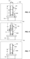
- images may be captured before aspiration, as shown in FIG. 5 , during aspiration as shown in FIG. 6 , or after aspiration, as in FIG. 7 .
- the image processor 112 may be operable to process the various captured images to determine various physical dimension aspects of the bio-liquid specimen 108S, and RBC portion 108R (if present) and/or pipette 104.
- a first captured image 520 that has been captured with the image capture device 109A may be analyzed and processed by the image processor 112 to determine a container height (Hc) and/or container diameter (Dc) of the bio-liquid container 108.
- the first captured image 520 may be analyzed and processed to obtain an initial height (H1) of the top-most meniscus portion of the bio-liquid specimen 108S from a datum, such as a top of the first support article 103 before aspiration takes place. From this, an initial aspiration volume (V1) may be determined. If a second component of the specimen is present, such as a RBC portion 108R, the uppermost height (Hr) of the RBC portion 108R may also be determined.
- a second image 620 may be captured with the image capture device 109A at a point when the pipette 104 is immersed in the bio-liquid specimen 108S and ready to aspirate.
- This image may be processed by the image processor 112 to determine and/or verify a depth of insertion (Di) and test that determined depth against one or more threshold depths in memory.
- a depth of insertion Di
- H1 initial height
- Dd pipette insertion depth
- each respective image that is captured by the image capture device 109A may be saved in memory as an archive. Additionally, each respective image that is captured by the image capture device 109A may be correlated with stored images in memory to determine any anomalies of the pipette 104, such as a damaged tip of the pipette 104, improper tip alignment, improper start position for tip, improper location of the bio-liquid container 108 in the first support article 103, or the like.
- the pipette 104 may be withdrawn from the bio-liquid container 108, and a third captured image 720 may be obtained with the capture device 109A.
- This third captured image 720 may be analyzed and processed by the image processor 112 to obtain an after-aspiration height (H2) of the top-most liquid meniscus from the datum, such as a top of the first support article 103.
- a height change difference (delta H) between H1 and H2, or a volume change calculated by using delta H and Dc may be used to measure and/or verify the aspiration. This verification may be in addition to, or in replacement of, a verification that may be provided by monitoring aspiration pressure with a sensor 130 during the aspiration.
- the second support article 105 containing the second bi-liquid container 120 (e.g., a cuvette) may be imaged by an image capture device 109B.
- image capture device 109B may be the same type of digital camera as discussed for Image capture device 109A.
- Image capture device 109B may be operable to capture one or more images of the second bio-liquid container 120 at one or more points in time during a bio-liquid dispense. For example, as in the aspiration, two or more images captured before, during, or after dispense may be captured.
- the differential heights measurements may be used alone, or may be used to determine the dispensed volume and/or to verify proper dispense.
- an image may be analyzed by the image processor 112 and used to verify that a second bio-liquid container 120 (e.g., cuvette) is indeed present in the receptacle of the second support article 105 (e.g., incubation ring). Insertion depth of the pipette 104 in the second bio-liquid container 120 may also be set and/or verified.
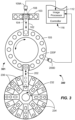
- FIG. 2 illustrates a top view of some components of a diagnostic device 100 with conventional components not shown such as a test reader (e.g., luminometer), cuvette loader, tip storage, motors, and the like.
- the diagnostic device 100 including the transfer apparatus 101 includes the first image capture device 109A located adjacent to a side of the first support article 103 (e.g., a five-position sample rack), second image capture device 109B located adjacent to a side of the second support article 105 (e.g., an inside of an incubation ring), and robot 102 adapted to move the pipette 104 (shown dotted) along the direction of arrow.
- first image capture device 109A located adjacent to a side of the first support article 103 (e.g., a five-position sample rack)
- second image capture device 109B located adjacent to a side of the second support article 105 (e.g., an inside of an incubation ring)
- robot 102 adapted to move the pipette
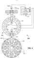
- a pipette 204 (shown dotted) moveable by a second robot 202 may dispense one or more reagents from the primary reagent containers 234 and/or ancillary reagent containers 236.
- One second robot 202 and coupled pipette 204 is shown. However, multiple robots and coupled pipettes may be used for the various reagent additions.
- the image capture device 209C may capture one or more images of the bio-liquid container 220 before, during, or after reagent addition. Thus, a change in height of the liquid in the bio-liquid container 220 before, during, and after reagent addition may be determined.
- the captured image may be analyzed using a blob analysis.
- image analysis may be performed looking at differences in digital counts within the captured image, as well as pixel locations within the images to determine edges between components.
- Logical group edge detection may also be used.
- Suitable masking, filtering and compression of the images may be used during processing, as is conventional in image processing.
- the blob analysis may obtain various Z or other coordinates, which may be based on a priori knowledge, for determining the discussed heights, widths, calculating volumes, pipette tip location, pipette tip misalignment (laterally and/or angularly), and/or various dimensions of the bio-liquid container 108, 120, 220, and/or 220F.
- Images may be captured as discussed herein by one or more image capture devices 109A, 109B, 109C, and/or 109D (e.g., digital cameras or the like) and analyzed by the image processor 112.
- image capture devices 109A, 109B, 109C, and/or 109D e.g., digital cameras or the like
- two images are captured and analyzed to determine a change in height or volume during the aspiration and/or dispense.
Landscapes
- Physics & Mathematics (AREA)
- Chemical & Material Sciences (AREA)
- Health & Medical Sciences (AREA)
- General Physics & Mathematics (AREA)
- General Health & Medical Sciences (AREA)
- Immunology (AREA)
- Analytical Chemistry (AREA)
- Biochemistry (AREA)
- Life Sciences & Earth Sciences (AREA)
- Pathology (AREA)
- Electromagnetism (AREA)
- Clinical Laboratory Science (AREA)
- Chemical Kinetics & Catalysis (AREA)
- Robotics (AREA)
- Engineering & Computer Science (AREA)
- Thermal Sciences (AREA)
- Fluid Mechanics (AREA)
- Automatic Analysis And Handling Materials Therefor (AREA)
Claims (9)
- Verfahren zum Bestimmen einer Ansaugung und/oder Abgabe, umfassend:Bereitstellen eines Bioflüssigkeitsbehälters (108);Ansaugen oder Abgeben verschiedener Assay-Komponenten aus dem oder an den Bioflüssigkeitsbehälter (108);gekennzeichnet durch die folgenden Schritte:- Erfassen eines Bildes an einem Punkt, wenn eine Pipette (104) in den Bioflüssigkeitsbehälter (108) eingetaucht wird;- Verarbeiten des Bildes durch einen Bildprozessor (112), um eine Eintauchtiefe (Di) der Pipette (104) zu bestimmen und/oder verifizieren;- Erfassen wenigstens eines oder mehrerer Bilder zu einem oder mehreren Zeitpunkten während des Ansaugens oder während der Abgabe;- Bestimmen des angesaugten oder abgegebenen Volumens basierend auf den wenigstens zwei Bildern, die durch einen Rechenalgorithmus des Bildprozessors (112) verarbeitet werden, um verschiedene Höhen- (Hc, H1, H2, Hr) und/oder Volumenänderungen aufgrund der Ansaugung oder Abgabe verschiedener Assay-Komponenten zu bestimmen und/oder verifizieren, und- Bestimmen, ob das Ansaugen oder das Abgeben ausreicht, basierend auf den wenigstens zwei Bildern.
- Verfahren nach Anspruch 1, umfassend:
Bestimmen einer Position oder Ausrichtung der Pipette (104) basierend auf einem Bild. - Verfahren nach Anspruch 1, umfassend:
Bestimmen einer Position der Pipette (104) in einer Flüssigkeit vor der Ansaugung basierend auf einem Bild. - Verfahren nach Anspruch 1, wobei der Bioflüssigkeitsbehälter umfasst:ein Blutentnahmeröhrchen odereine Küvette.
- Verfahren nach Anspruch 1, wobei das Erfassen der ein oder mehreren Bilder des Bioflüssigkeitsbehälters umfasst:a) Lokalisieren einer Bilderfassungsvorrichtung neben einer Seite eines Stützartikels, der dazu angepasst ist, den Bioflüssigkeitsbehälter zu stützen, oderb) Erfassen von wenigstens zwei Bildern der Ansaugung durch Lokalisieren einer Bilderfassungsvorrichtung neben einer Seite eines Blutentnahmeröhrchens, das sich in einem Probengestell befindet, oderc) Lokalisieren einer Bilderfassungsvorrichtung neben einer Seite einer Küvette, die sich in einem Inkubationsring befindet, oderd) Erfassen von wenigstens zwei Bildern der Abgabe an einer Seite einer Küvette, die sich in einem Inkubationsring befindet, odere) Lokalisieren einer Bilderfassungsvorrichtung neben einer Seite einer Küvette an einem Ort der Reagenszugabe in einem Inkubationsring oderf) Lokalisieren einer Bilderfassungsvorrichtung an einem Ort, wo alle Assay-Teilkomponenten hinzugegeben worden sind.
- Diagnosevorrichtung, aufweisend eine Transfereinrichtung (301), wobei die Einrichtung dies umfasst:einen Stützartikel (103), der dazu angepasst ist, einen Bioflüssigkeitsbehälter (108) aufzunehmen; undeine Bilderfassungseinrichtung, die sich neben dem Stützartikel (103) befindet, dadurch gekennzeichnet, dassdie Bilderfassungseinrichtung betreibbar ist, um die Schritte des Bilderfassungsverfahrens nach Anspruch 1 zu implementieren, wobei die Transfereinrichtung ferner einen Bildprozessor (112) umfasst, der dazu ausgelegt ist, die Schritte des Verarbeitungs- und Bestimmungsverfahrens nach Anspruch 1 zu implementieren.
- Diagnosevorrichtung, aufweisend eine Transfereinrichtung nach Anspruch 6, wobei die Bilderfassungseinrichtung eine oder mehrere Digitalkameras umfasst.
- Diagnosevorrichtung, aufweisend eine Transfereinrichtung nach Anspruch 6, wobei sich die Bilderfassungseinrichtung:neben einer Seite eines Probengestells befindet und dazu angepasst ist, eine oder mehrere Volumenänderungen aufgrund der Ansaugung zu bestimmen;neben einer Seite eines Inkubationsrings befindet und dazu angepasst ist, eine oder mehrere Volumenänderungen aufgrund der Abgabe zu bestimmen; undneben einer Seite eines Inkubationsrings befindet und dazu angepasst ist, eine Gesamtvolumentänderung aufgrund von Assay-Teilkomponentenzugaben zu bestimmen.
- Diagnosevorrichtung, aufweisend eine Transfereinrichtung nach Anspruch 6, umfassend:eine Transfereinrichtung, aufweisendeinen ersten Stützartikel, der dazu angepasst ist, einen ersten Bioflüssigkeitsbehälter aufzunehmen, welcher eine Bioflüssigkeit enthält;einen zweiten Stützartikel, der dazu angepasst ist, einen zweiten Bioflüssigkeitsbehälter aufzunehmen;eine Bilderfassungseinrichtung, die sich neben einem oder mehreren hiervon befindet:dem ersten Stützartikel, betreibbar, um mehr als ein Bild des Bioflüssigkeitsbehälters zu mehr als einem Zeitpunkt während einer Bioflüssigkeitsansaugung zu erfassen,dem zweiten Stützartikel, betreibbar, um mehr als ein Bild des zweiten Bioflüssigkeitsbehälters zu mehr als einem Zeitpunkt während einer Bioflüssigkeitsabgabe zu erfassen,dem zweiten Stützartikel, betreibbar, um mehr als ein Bild des zweiten Bioflüssigkeitsbehälters zu mehr als einem Zeitpunkt während einer Reagensabgabe zu erfassen, unddem zweiten Stützartikel, betreibbar, um ein oder mehrere Bilder des zweiten Bioflüssigkeitsbehälters nach allen Assay-Teilkomponentenzugaben zu erfassen; undeinen Bildprozessor, der dazu betreibbar ist, die Bilder zu verarbeiten, um wenigstens eines zu bestimmen, ausgewählt aus einer Gruppe bestehend aus:Ansaughöhe oder Ansaugvolumen,Abgabehöhe oder Abgabevolumen,allgemeine Höhen- oder Volumenzunahme undKombinationen davon.
Applications Claiming Priority (2)
| Application Number | Priority Date | Filing Date | Title |
|---|---|---|---|
| US201361899424P | 2013-11-04 | 2013-11-04 | |
| PCT/US2014/063186 WO2015066342A1 (en) | 2013-11-04 | 2014-10-30 | Methods and apparatus for determining aspiration and/or dispensing volume and/or pipette positioning |
Publications (3)
| Publication Number | Publication Date |
|---|---|
| EP3065797A1 EP3065797A1 (de) | 2016-09-14 |
| EP3065797A4 EP3065797A4 (de) | 2016-11-09 |
| EP3065797B1 true EP3065797B1 (de) | 2025-07-02 |
Family
ID=53005130
Family Applications (1)
| Application Number | Title | Priority Date | Filing Date |
|---|---|---|---|
| EP14858935.1A Active EP3065797B1 (de) | 2013-11-04 | 2014-10-30 | Verfahren und vorrichtung zur bestimmung der aspirations- und/oder ausgabemenge und/oder pipettenpositionierung |
Country Status (3)
| Country | Link |
|---|---|
| US (1) | US9915675B2 (de) |
| EP (1) | EP3065797B1 (de) |
| WO (1) | WO2015066342A1 (de) |
Families Citing this family (17)
| Publication number | Priority date | Publication date | Assignee | Title |
|---|---|---|---|---|
| US10078778B2 (en) | 2015-01-15 | 2018-09-18 | Massachusetts Institute Of Technology | Systems, methods, and apparatus for in vitro single-cell identification and recovery |
| US10837977B2 (en) | 2015-05-11 | 2020-11-17 | Kabushiki Kaisha Yaskawa Denki | Rack for dispensing and dispensing system |
| WO2016181466A1 (ja) * | 2015-05-11 | 2016-11-17 | 株式会社安川電機 | 分注システム、コントローラ及び制御方法 |
| EP3118628B1 (de) * | 2015-07-13 | 2021-08-25 | Siemens Healthcare Diagnostics Products GmbH | Verfahren zum pipettieren von flüssigkeiten in einem automatischen analysegerät |
| CN110023950B (zh) | 2016-10-28 | 2023-08-08 | 拜克门寇尔特公司 | 物质准备评估系统 |
| US10864515B2 (en) | 2016-11-11 | 2020-12-15 | Walid Habbal | Automated pipette manipulation system |
| GB201704760D0 (en) * | 2017-01-05 | 2017-05-10 | Illumina Inc | Reagent nozzle sipper mixing system and method |
| WO2019023376A1 (en) * | 2017-07-28 | 2019-01-31 | Siemens Healthcare Diagnostics Inc. | METHODS AND APPARATUS FOR QUANTIFYING DEEP LEARNING VOLUME |
| EP3550308A1 (de) * | 2018-04-05 | 2019-10-09 | Siemens Healthcare Diagnostics Products GmbH | Laboranalysesystem mit verbesserter probenpipettierung |
| US11808778B2 (en) | 2018-04-25 | 2023-11-07 | Siemens Healthcare Diagnostics Inc. | Intelligent pressure control apparatus and methods for maintaining manifold pressure in a diagnostic testing apparatus |
| EP3870940B1 (de) | 2018-12-03 | 2023-10-18 | Bio-Rad Laboratories, Inc. | Flüssigkeitsstandbestimmung |
| EP3745081B1 (de) * | 2019-05-28 | 2023-03-22 | Tecan Trading Ag | Positionsdetektor und verfahren zur 3d-positionsbestimmung |
| WO2021091755A1 (en) * | 2019-11-05 | 2021-05-14 | Siemens Healthcare Diagnostics Inc. | Systems, apparatus, and methods of analyzing specimens |
| IT201900021264A1 (it) | 2019-11-15 | 2021-05-15 | Macs S R L | Dispositivo e metodo di certificazione delle operazioni di una macchina di analisi diagnostica in vitro |
| IT202100001649A1 (it) * | 2021-01-27 | 2022-07-27 | Macs S R L | Sistema di scansione 3d per la mappatura di piani di lavoro nella diagnostica in vitro |
| JP2024039362A (ja) * | 2022-09-09 | 2024-03-22 | 株式会社島津製作所 | 自動分注装置 |
| WO2025205519A1 (ja) * | 2024-03-25 | 2025-10-02 | 積水メディカル株式会社 | 情報提示装置、情報提示方法、およびプログラム |
Family Cites Families (22)
| Publication number | Priority date | Publication date | Assignee | Title |
|---|---|---|---|---|
| AUPP058197A0 (en) * | 1997-11-27 | 1997-12-18 | A.I. Scientific Pty Ltd | Pathology sample tube distributor |
| US7750817B2 (en) * | 1999-12-10 | 2010-07-06 | Beverage Metrics Holding Ltd | System and method using a scale for monitoring the dispensing of a beverage |
| US6370942B1 (en) | 2000-05-15 | 2002-04-16 | Dade Behring Inc. | Method for verifying the integrity of a fluid transfer |
| US7186378B2 (en) | 2003-07-18 | 2007-03-06 | Dade Behring Inc. | Liquid sampling probe and cleaning fluidics system |
| JP4162086B2 (ja) * | 2003-08-26 | 2008-10-08 | Tdk株式会社 | 液体材料塗布方法 |
| KR20060082641A (ko) * | 2005-01-13 | 2006-07-19 | 삼성전자주식회사 | 액정 적하량 측정 시스템 및 이를 이용한 액정 적하량측정 방법 |
| US7499581B2 (en) * | 2005-02-10 | 2009-03-03 | Forhealth Technologies, Inc. | Vision system to calculate a fluid volume in a container |
| US7150190B2 (en) | 2005-03-21 | 2006-12-19 | Dade Behring Inc. | Method and apparatus for capacitively determining the uppermost level of a liquid in a container |
| US20070107801A1 (en) * | 2005-11-14 | 2007-05-17 | Sidel And Pressco Technology Inc. | Bottle filling machine with sensor and method thereof |
| US7477997B2 (en) | 2005-12-19 | 2009-01-13 | Siemens Healthcare Diagnostics Inc. | Method for ascertaining interferants in small liquid samples in an automated clinical analyzer |
| US20080169044A1 (en) * | 2006-10-20 | 2008-07-17 | Forhealth Technologies, Inc. | Automated drug preparation apparatus including syringe loading, preparation and filling |
| US7867769B2 (en) | 2007-09-19 | 2011-01-11 | Siemens Healthcare Diagnostics Inc. | Clog detection in a clinical sampling pipette |
| US7634378B2 (en) | 2007-11-30 | 2009-12-15 | Siemens Healthcare Diagnostics Inc. | Detection of insufficient sample during aspiration with a pipette |
| US8161810B2 (en) * | 2008-01-29 | 2012-04-24 | Carefusion 303, Inc. | Syringe imaging systems |
| US8763651B2 (en) * | 2008-02-01 | 2014-07-01 | Rescue Dose Ltd. | Dosage dispensing device |
| JP5465850B2 (ja) * | 2008-08-01 | 2014-04-09 | シスメックス株式会社 | 試料分析システム |
| JP5859439B2 (ja) | 2009-08-13 | 2016-02-10 | シーメンス・ヘルスケア・ダイアグノスティックス・インコーポレイテッド | 臨床分析機によって分析される液体サンプルおよび容器の中の干渉物質および物理的寸法を確定するための方法ならびに装置 |
| US7982201B2 (en) * | 2009-09-08 | 2011-07-19 | Jadak, Llc | System and method for detection of liquid level in a vessel |
| US9821306B2 (en) * | 2010-11-23 | 2017-11-21 | Andrew Alliance S.A. | Devices and methods for programmable manipulation of pipettes |
| CN106290159A (zh) * | 2011-01-21 | 2017-01-04 | 提拉诺斯公司 | 样品使用最大化的系统和方法 |
| CA2977889C (en) | 2011-09-09 | 2019-02-12 | Gen-Probe Incorporated | Automated sample handling instrumentation, systems, processes, and methods |
| EP2874889B1 (de) * | 2012-07-23 | 2018-11-28 | Pharmadva LLC | Objektspender mit variabler öffnung und bildidentifikation |
-
2014
- 2014-10-30 EP EP14858935.1A patent/EP3065797B1/de active Active
- 2014-10-30 US US15/034,442 patent/US9915675B2/en active Active
- 2014-10-30 WO PCT/US2014/063186 patent/WO2015066342A1/en not_active Ceased
Also Published As
| Publication number | Publication date |
|---|---|
| EP3065797A1 (de) | 2016-09-14 |
| US9915675B2 (en) | 2018-03-13 |
| WO2015066342A1 (en) | 2015-05-07 |
| US20160291049A1 (en) | 2016-10-06 |
| EP3065797A4 (de) | 2016-11-09 |
Similar Documents
| Publication | Publication Date | Title |
|---|---|---|
| EP3065797B1 (de) | Verfahren und vorrichtung zur bestimmung der aspirations- und/oder ausgabemenge und/oder pipettenpositionierung | |
| CN102066949B (zh) | 自动分析装置 | |
| JP2013536951A (ja) | 全血混合の完全さを決定するための全血吸引の圧力モニタリング | |
| US9897623B2 (en) | Automatic analyzer | |
| WO2015111442A1 (ja) | 自動分析装置 | |
| JP7200357B2 (ja) | 実験器具の動作方法 | |
| US12360523B2 (en) | Systems, apparatus, and methods of analyzing specimens | |
| JP7668091B2 (ja) | ピペッティングされる液体の投与を光学的に監視するための装置 | |
| EP1894017A2 (de) | Verfahren zur ermittlung interferierender substanzen in kleinen flüssigkeitsproben in einem automatisierten klinischen analysegerät | |
| KR20170122147A (ko) | 주사기 조립체 및 주사기 조립체 사용 방법 | |
| JP2005017144A (ja) | 自動分析装置 | |
| JP7613913B2 (ja) | 反応容器及び自動分析装置 | |
| JP2592837B2 (ja) | 自動化学分析装置 | |
| EP4136462B1 (de) | Automatisches probenahmeverfahren zur handhabung von vollblut | |
| EP4155736B1 (de) | Adaptive lichtschrankenverarbeitung | |
| US20220268796A1 (en) | Method of Operating a Laboratory Instrument | |
| WO2022185919A1 (ja) | 自動分析装置、および検体の分注方法 | |
| HK40068286A (en) | Systems, apparatus, and methods of analyzing specimens | |
| CN120009521A (zh) | 样本分析设备、样本分析方法及介质 |
Legal Events
| Date | Code | Title | Description |
|---|---|---|---|
| PUAI | Public reference made under article 153(3) epc to a published international application that has entered the european phase |
Free format text: ORIGINAL CODE: 0009012 |
|
| 17P | Request for examination filed |
Effective date: 20160606 |
|
| AK | Designated contracting states |
Kind code of ref document: A1 Designated state(s): AL AT BE BG CH CY CZ DE DK EE ES FI FR GB GR HR HU IE IS IT LI LT LU LV MC MK MT NL NO PL PT RO RS SE SI SK SM TR |
|
| AX | Request for extension of the european patent |
Extension state: BA ME |
|
| A4 | Supplementary search report drawn up and despatched |
Effective date: 20161007 |
|
| RIC1 | Information provided on ipc code assigned before grant |
Ipc: A61M 5/00 20060101AFI20161003BHEP Ipc: B01L 3/02 20060101ALI20161003BHEP Ipc: G01N 35/10 20060101ALI20161003BHEP |
|
| DAX | Request for extension of the european patent (deleted) | ||
| STAA | Information on the status of an ep patent application or granted ep patent |
Free format text: STATUS: EXAMINATION IS IN PROGRESS |
|
| 17Q | First examination report despatched |
Effective date: 20191001 |
|
| GRAP | Despatch of communication of intention to grant a patent |
Free format text: ORIGINAL CODE: EPIDOSNIGR1 |
|
| STAA | Information on the status of an ep patent application or granted ep patent |
Free format text: STATUS: GRANT OF PATENT IS INTENDED |
|
| INTG | Intention to grant announced |
Effective date: 20250203 |
|
| P01 | Opt-out of the competence of the unified patent court (upc) registered |
Free format text: CASE NUMBER: APP_13317/2025 Effective date: 20250318 |
|
| GRAS | Grant fee paid |
Free format text: ORIGINAL CODE: EPIDOSNIGR3 |
|
| GRAA | (expected) grant |
Free format text: ORIGINAL CODE: 0009210 |
|
| STAA | Information on the status of an ep patent application or granted ep patent |
Free format text: STATUS: THE PATENT HAS BEEN GRANTED |
|
| AK | Designated contracting states |
Kind code of ref document: B1 Designated state(s): AL AT BE BG CH CY CZ DE DK EE ES FI FR GB GR HR HU IE IS IT LI LT LU LV MC MK MT NL NO PL PT RO RS SE SI SK SM TR |
|
| REG | Reference to a national code |
Ref country code: GB Ref legal event code: FG4D |
|
| REG | Reference to a national code |
Ref country code: CH Ref legal event code: EP |
|
| REG | Reference to a national code |
Ref country code: DE Ref legal event code: R096 Ref document number: 602014092094 Country of ref document: DE |
|
| REG | Reference to a national code |
Ref country code: IE Ref legal event code: FG4D |
|
| REG | Reference to a national code |
Ref country code: NL Ref legal event code: MP Effective date: 20250702 |