EP4155736B1 - Adaptive lichtschrankenverarbeitung - Google Patents
Adaptive lichtschrankenverarbeitung Download PDFInfo
- Publication number
- EP4155736B1 EP4155736B1 EP22188202.0A EP22188202A EP4155736B1 EP 4155736 B1 EP4155736 B1 EP 4155736B1 EP 22188202 A EP22188202 A EP 22188202A EP 4155736 B1 EP4155736 B1 EP 4155736B1
- Authority
- EP
- European Patent Office
- Prior art keywords
- voltage values
- voltage
- median
- level
- target
- Prior art date
- Legal status (The legal status is an assumption and is not a legal conclusion. Google has not performed a legal analysis and makes no representation as to the accuracy of the status listed.)
- Active
Links
Images
Classifications
-
- G—PHYSICS
- G01—MEASURING; TESTING
- G01N—INVESTIGATING OR ANALYSING MATERIALS BY DETERMINING THEIR CHEMICAL OR PHYSICAL PROPERTIES
- G01N35/00—Automatic analysis not limited to methods or materials provided for in any single one of groups G01N1/00 - G01N33/00; Handling materials therefor
- G01N35/10—Devices for transferring samples or any liquids to, in, or from, the analysis apparatus, e.g. suction devices, injection devices
- G01N35/1009—Characterised by arrangements for controlling the aspiration or dispense of liquids
- G01N35/1011—Control of the position or alignment of the transfer device
-
- G—PHYSICS
- G01—MEASURING; TESTING
- G01N—INVESTIGATING OR ANALYSING MATERIALS BY DETERMINING THEIR CHEMICAL OR PHYSICAL PROPERTIES
- G01N21/00—Investigating or analysing materials by the use of optical means, i.e. using sub-millimetre waves, infrared, visible or ultraviolet light
- G01N21/17—Systems in which incident light is modified in accordance with the properties of the material investigated
- G01N21/59—Transmissivity
-
- G—PHYSICS
- G01—MEASURING; TESTING
- G01N—INVESTIGATING OR ANALYSING MATERIALS BY DETERMINING THEIR CHEMICAL OR PHYSICAL PROPERTIES
- G01N35/00—Automatic analysis not limited to methods or materials provided for in any single one of groups G01N1/00 - G01N33/00; Handling materials therefor
- G01N35/00584—Control arrangements for automatic analysers
- G01N35/00594—Quality control, including calibration or testing of components of the analyser
- G01N35/00693—Calibration
-
- G—PHYSICS
- G01—MEASURING; TESTING
- G01N—INVESTIGATING OR ANALYSING MATERIALS BY DETERMINING THEIR CHEMICAL OR PHYSICAL PROPERTIES
- G01N35/00—Automatic analysis not limited to methods or materials provided for in any single one of groups G01N1/00 - G01N33/00; Handling materials therefor
- G01N35/10—Devices for transferring samples or any liquids to, in, or from, the analysis apparatus, e.g. suction devices, injection devices
- G01N35/1004—Cleaning sample transfer devices
-
- G—PHYSICS
- G01—MEASURING; TESTING
- G01N—INVESTIGATING OR ANALYSING MATERIALS BY DETERMINING THEIR CHEMICAL OR PHYSICAL PROPERTIES
- G01N35/00—Automatic analysis not limited to methods or materials provided for in any single one of groups G01N1/00 - G01N33/00; Handling materials therefor
- G01N35/10—Devices for transferring samples or any liquids to, in, or from, the analysis apparatus, e.g. suction devices, injection devices
- G01N35/1009—Characterised by arrangements for controlling the aspiration or dispense of liquids
- G01N35/1016—Control of the volume dispensed or introduced
-
- G—PHYSICS
- G01—MEASURING; TESTING
- G01N—INVESTIGATING OR ANALYSING MATERIALS BY DETERMINING THEIR CHEMICAL OR PHYSICAL PROPERTIES
- G01N35/00—Automatic analysis not limited to methods or materials provided for in any single one of groups G01N1/00 - G01N33/00; Handling materials therefor
- G01N35/00584—Control arrangements for automatic analysers
- G01N35/00594—Quality control, including calibration or testing of components of the analyser
- G01N35/00613—Quality control
- G01N35/00663—Quality control of consumables
- G01N2035/00683—Quality control of consumables of detectors
-
- G—PHYSICS
- G01—MEASURING; TESTING
- G01N—INVESTIGATING OR ANALYSING MATERIALS BY DETERMINING THEIR CHEMICAL OR PHYSICAL PROPERTIES
- G01N35/00—Automatic analysis not limited to methods or materials provided for in any single one of groups G01N1/00 - G01N33/00; Handling materials therefor
- G01N35/10—Devices for transferring samples or any liquids to, in, or from, the analysis apparatus, e.g. suction devices, injection devices
- G01N35/1009—Characterised by arrangements for controlling the aspiration or dispense of liquids
- G01N2035/1025—Fluid level sensing
Definitions
- the invention relates to a method for adaptive signal processing.
- Automated analyser systems for use in clinical diagnostics and life sciences are produced by a number of companies.
- STRATEC ® SE Birkenfeld, Germany
- IVD devices for processing diagnostic assays comprise many individual device components, hereinafter also referred to as modules. These modules take over individual processing steps in the sequence of processing the samples. The functionality required for these processing steps is provided by the firmware of the modules. Generally, data is collected during the processing of samples and checked by means of a process control. Process control is used to analyze the collected parameters and to ensure a correct analysis procedure. If an erroneous behavior is detected during process control, the currently processed sample is discarded, if necessary.
- a central task of processing samples in IVD devices is the movement of liquids, or the correct transport of consumables comprising a sample such as cuvettes during processing in the device.
- an accurate assessment of the amount of liquid and the position of the consumables is crucial.
- These processes can be monitored using light barrier sensors.
- a light source shines through the medium to be measured for a defined time per measurement. To that end the light intensity is measured with a photodiode which is arranged usually opposite to the light source. The measured light signal is recorded as varying voltages which must now be analyzed to distinguish between the actual signal and the background noise.
- the rate at which aspirate is pumped and the volume of the tube from a probe tip inlet to the detector are known constants. Therefore, a given volume of aspirate takes a predictable amount of time to pass from tip to detector.
- the actual time is determined by measuring the elapsed time between the start of the aspiration of a reagent, and a liquid-air transition detected at the end of the aspirated reagent. If the liquid-air transition is not seen at the expected time, one of several problems with the system are assumed, and the assay is cancelled.
- the disadvantage of the disclosed apparatus and method relates to the fact that no adaptive signal processing is provided.
- Static process control known from the prior art like U.S. patent 5,777,221 for distinguishing between signal and background noise may lead to incorrect evaluations in certain cases.
- the reason for this is the static approach of signal processing.
- the known approach can only react in discrete steps to changes in the media arranged between the light source and the photodiode. This is done in the context of a regular recalibration of the system.
- the sensor system cannot react to changes of the media in the system between two calibrations. This circumstance can lead to errors in the evaluation.
- the present invention provides a method for adaptive signal processing, comprising the steps of illuminating the content in a container with a light source from one side of the container; measuring the optical signal with a sensor resulting from light shining through the container and its content; assigning voltage values to the measured optical signals; preparing a voltage curve from sampled measurements of voltage values over time; determining a voltage level of a background noise level; performing a first plausibility check to verify whether a target signal is already present at the beginning of the measurement by reducing the voltage values by a defined factor to a preset fallback level if the median of measured voltage values at the beginning of the voltage curve is outside a tolerance range with a value that is more than 50% higher than an expected target value of a system calibration, or proceeding with the median voltage values if the measured voltage at the beginning of the voltage curve is within the tolerance range or is lower than the expected value of the system calibration, determining the voltage level of a target signal by calculating the median of a group of the highest measured voltage values, performing a second plausibility check by
- Another aspect of the present invention relates to the step of determining voltage values in a running process for process control.
- the median of voltage values from the beginning comprises the median value of pre-defined number of measured voltage values.
- the median of the group of highest voltage values is defined from a pre-defined number of measured highest voltage values.
- the method is stopped if the median of the measured voltage values in the first plausibility check is at least 50% higher.
- the method may comprise in another embodiment the step of measuring optical signal in a sample with a known concentration of a target for obtaining a voltage value for an expected target signal.
- the method may also comprise the step of measuring optical signal in a sample without a target for obtaining a voltage value for a noise level.
- the method refers to the understanding of a container being bottle, vessel, cuvette, tube, hose or a channel.
- Another object of the present disclosure relates to a method for process control of samples which are optically evaluated in a device comprising the steps of applying a method as described above.
- a container within the meaning of the present invention refers to any receptacle that is appropriate to comprise a fluid like a liquid, gas, or any other material that may flow under external force or shear stress.
- a container also refers to a hose, tube or a channel which may comprise a fluid or through which a fluid may flow.
- a container shall also be understood to be a well of a multi well plate or a bottle.
- One object of the present invention relates to a system comprising a light source and a photosensor.
- Another object of the invention relates to a method for adaptive signal processing of each trace originating from the photosensor.
- the method comprises an automatic detection of the voltage level of the target signal and the background noise. Based on the determined voltages advantageous decision limits are calculated.
- Such decision limits can be used to detect, for example, the temporal length of the signal. Due to a dynamic calculation of the decision limits, these limits are optimal for each measured voltage curve.
- the system is also able to detect a measurement with only noise and mark it as incomplete.
- a voltage curve within the meaning of the present disclosure is a sampled measurement of voltages from a photodiode over time, wherein the photodiode measures light intensities through a medium which is comprised in a container or consumable or flows through a hose, tube or channel.
- the voltage of the photodiode is recorded at a high frequency.
- the measured voltage levels differ depending on the kind of medium which is between light source and sensor at the respective time.
- a calibration is usually performed to obtain a comparable voltage level (target value of the system calibration) for the background noise over time.
- the calibration is performed on all instruments according to the same scheme to allow comparability between the instruments.
- the period with signal should now be distinguished from the period with background noise.
- the voltage level of the background noise which is usually present at the beginning of each curve, is first determined for each individual voltage curve.
- the first 40 values of the curve are analyzed, and the median of these values is calculated.
- a plausibility check is performed to verify whether the target signal is already present at the beginning of the measurement. This case is assumed if the measured voltage at the beginning of the curve is more than 50% higher than the target value of the system calibration. In this case the voltage level is assessed to be too high, so that a preset fallback for the voltage level for the noise is assumed, to allow for the calculation to take place. The value of the fallback depends on the application.
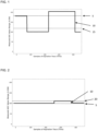
- FIG. 1 illustrates such a case of plausibility check on an exemplary voltage curve.
- the algorithm has determined a noise level 5 of approximately 180 from the first 40 values of the voltage curve 10.
- the determined noise level is 80 % above the specified target value of 100 and thus outside the tolerance range of 50 %. In this case, the voltage value of the first 40 determined values is too high.
- a preset fallback 15 with a fixed voltage level of e.g. 120 is assumed for the further evaluations.
- the procedure of the first plausibility check depends on the target application. In critical applications, a preset fallback is not permitted. With these voltage curves, if the voltage level of the background noise is increased, the voltage curve is generally marked as faulty.
- the voltage level of the target signal is determined. This is done, for example, by sorting the 5 highest values of the trace and calculating the median of these values. This is done to compensate for individual error measurements of the voltage.
- FIG. 2 An example of a faulty voltage curve is shown in FIG. 2 .
- the determined noise level 5 is within the specifications from the first plausibility check. In this example, the determined noise level 5 is 100.
- the calculation of the median results in a value of 110 for the signal level 20.
- the voltage difference of the calculated levels is thus 10% and is below the specified minimum difference. Consequently, the discrimination of the calculated levels is too small for the further evaluations.
- the second plausibility check marks the curve shown in FIG. 2 as faulty.
- the discrimination limit is set exactly in the middle between the two calculated levels.
- the resulting calculated boundary now allows a distinction between noise level and signal level. This boundary is used to determine the length of the target signal above the boundary. The result can then be used for further process controls.
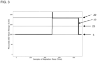
- FIG. 3 shows an example voltage curve 10 that has successfully completed all plausibility checks. From the analysis of the first 40 values of the voltage curve 10, the algorithm determined a noise level 5 of 100. For the first plausibility check, the determined noise level 5 is within the tolerance range of the target value of the system calibration. Now, in the second plausibility check, the voltage difference of the calculated levels is determined. By calculating the median of the five highest values from the voltage curve 10, a signal level 20 of 180 was determined. There is thus a sufficiently large voltage difference of 80% between the noise level 5 and the signal level 20, so that the calculated limit 25 of 140 is obtained in the middle of the two levels 5, 20. Signals below the limit 25 of 140 are thus noise level 5 and values above the limit 25 of 140 are target signals. This distinction can now be used for process controls.
- Another alternative is to manually inspect the measurement system on a regular basis to detect any deviations and correct them if necessary. This would also be a very time-consuming procedure, which would require trained personnel.
Landscapes
- Physics & Mathematics (AREA)
- Health & Medical Sciences (AREA)
- Life Sciences & Earth Sciences (AREA)
- Chemical & Material Sciences (AREA)
- Analytical Chemistry (AREA)
- Biochemistry (AREA)
- General Health & Medical Sciences (AREA)
- General Physics & Mathematics (AREA)
- Immunology (AREA)
- Pathology (AREA)
- Engineering & Computer Science (AREA)
- Quality & Reliability (AREA)
- Measurement Of Levels Of Liquids Or Fluent Solid Materials (AREA)
- Automatic Analysis And Handling Materials Therefor (AREA)
Claims (9)
- Ein Verfahren zur adaptiven Signalverarbeitung, das die folgenden Schritte umfasst- Beleuchten des Inhalts in einem Behälter mit einer Lichtquelle von einer Seite des Behälters aus;- Messung des optischen Signals mit einem Sensor, das sich aus dem Licht ergibt, das durch den Behälter und seinen Inhalt scheint;- Zuordnung von Spannungswerten zu den gemessenen optischen Signalen;- Erstellung einer Spannungskurve aus abgetasteten Messungen von Spannungswerten im Zeitverlauf;- Bestimmung eines Spannungspegels eines Hintergrundgeräuschpegels;- Durchführung einer ersten Plausibilitätsprüfung, um festzustellen, ob ein Zielsignal bereits zu Beginn der Messung vorhanden ist; durcha. Reduzieren der Spannungswerte um einen definierten Faktor auf ein vorgegebenes Rückfallniveau, wenn der Median der gemessenen Spannungswerte am Anfang des Spannungsverlaufs außerhalb eines Toleranzbereichs liegt, mit einem Wert, der mehr als 50% über einem erwarteten Zielwert einer Systemkalibrierung liegt; oderb. mit den mittleren Spannungswerten fortzufahren, wenn die gemessene Spannung am Anfang der Spannungskurve innerhalb des Toleranzbereichs liegt oder niedriger als der erwartete Zielwert der Systemkalibrierung ist;- Bestimmung des Spannungspegels eines Zielsignals durch Berechnung des Medians einer Gruppe der höchsten gemessenen Spannungswerte;i. Durchführung einer zweiten Plausibilitätsprüfung, indem festgestellt wird, ob der Median einer Gruppe von höchsten Zielspannungswerten mindestens 20 % höher ist als die definierten Spannungswerte des Hintergrundgeräuschpegels oder des voreingestellten Rückfallpegels;- nur dann mit dem Verfahren fortzufahren, wenn der Median der Gruppe der höchsten Spannungswerte um mindestens 20 % von den definierten Spannungswerten des Hintergrundgeräuschpegels oder eines voreingestellten Rückfallpegels abweicht, indem Unterscheidungsgrenzen zwischen den Spannungswerten, die sich auf einen Hintergrundgeräuschpegel bzw. einen Zielpegel beziehen, bestimmt werden, indem die Unterscheidungsgrenze in der Mitte zwischen dem Hintergrundgeräuschpegel und dem Signalpegel festgelegt wird.
- Das Verfahren nach Anspruch 1, umfassend den Schritt der Bestimmung von Spannungswerten in einem laufenden Prozess zur Prozesssteuerung.
- Das Verfahren nach Anspruch 1 oder 2, wobei der Median der Spannungswerte von Anfang an den Medianwert einer vordefinierten Anzahl von gemessenen Spannungswerten umfasst.
- Das Verfahren nach einem der Ansprüche 1 bis 3, wobei der Median der Gruppe der höchsten Spannungswerte aus einer vordefinierten Anzahl von gemessenen höchsten Spannungswerten bestimmt wird.
- Das Verfahren nach einem der Ansprüche 1 bis 4, wobei das Verfahren gestoppt wird, wenn der Median der gemessenen Spannungswerte in der ersten Plausibilitätsprüfung um mindestens 50 % höher ist als ein erwarteter Zielwert einer Systemkalibrierung.
- Das Verfahren nach einem der Ansprüche 1 bis 5, umfassend den Schritt des Messens des optischen Signals in einer Probe mit einer bekannten Konzentration eines Targets, um einen Spannungswert für ein erwartetes Targetsignal zu erhalten.
- Das Verfahren nach einem der Ansprüche 1 bis 6, umfassend den Schritt der Messung des optischen Signals in einer Probe ohne Ziel, um einen Spannungswert für einen Rauschpegel zu erhalten.
- Das Verfahren nach einem der Ansprüche 1 bis 7, wobei ein Behälter eine Flasche, ein Gefäß, eine Küvette, ein Rohr, ein Schlauch oder ein Kanal ist.
- Ein Verfahren zur Prozesskontrolle von Proben, die in einer Vorrichtung optisch ausgewertet werden, umfassend die Schritte der Anwendung eines Verfahrens nach Anspruch 1.
Applications Claiming Priority (1)
| Application Number | Priority Date | Filing Date | Title |
|---|---|---|---|
| GBGB2113627.0A GB202113627D0 (en) | 2021-09-24 | 2021-09-24 | Adaptive light barrier processing |
Publications (2)
| Publication Number | Publication Date |
|---|---|
| EP4155736A1 EP4155736A1 (de) | 2023-03-29 |
| EP4155736B1 true EP4155736B1 (de) | 2025-01-29 |
Family
ID=78399750
Family Applications (1)
| Application Number | Title | Priority Date | Filing Date |
|---|---|---|---|
| EP22188202.0A Active EP4155736B1 (de) | 2021-09-24 | 2022-08-02 | Adaptive lichtschrankenverarbeitung |
Country Status (3)
| Country | Link |
|---|---|
| US (1) | US20230096436A1 (de) |
| EP (1) | EP4155736B1 (de) |
| GB (1) | GB202113627D0 (de) |
Family Cites Families (3)
| Publication number | Priority date | Publication date | Assignee | Title |
|---|---|---|---|---|
| CA2177658A1 (en) * | 1995-07-10 | 1997-01-11 | Kurukundi Ramesh Murthy | Volume detection apparatus and method |
| JP5251729B2 (ja) * | 2008-06-20 | 2013-07-31 | 株式会社島津製作所 | 分光光度計 |
| JP7347979B2 (ja) * | 2019-07-18 | 2023-09-20 | シスメックス株式会社 | 測定装置、測定装置の調整方法およびプログラム |
-
2021
- 2021-09-24 GB GBGB2113627.0A patent/GB202113627D0/en not_active Ceased
-
2022
- 2022-08-01 US US17/878,266 patent/US20230096436A1/en active Pending
- 2022-08-02 EP EP22188202.0A patent/EP4155736B1/de active Active
Also Published As
| Publication number | Publication date |
|---|---|
| US20230096436A1 (en) | 2023-03-30 |
| GB202113627D0 (en) | 2021-11-10 |
| EP4155736A1 (de) | 2023-03-29 |
Similar Documents
| Publication | Publication Date | Title |
|---|---|---|
| US10429401B2 (en) | Methods and systems for tube inspection and liquid level detection | |
| US9915675B2 (en) | Methods and apparatus for determining aspiration and/or dispensing volume and/or pipette positioning | |
| EP2277053B1 (de) | Verfahren und vorrichtung zur überprüfung der flüssigkeit in einer pipettenspitze | |
| US9506942B2 (en) | Automatic analyzer and method for detecting measurement value abnormalities | |
| EP3101431B1 (de) | Automatische analytische vorrichtung | |
| EP1607747B1 (de) | Messung einer Flüssigkeit mit eine kapazitive Uberwachung | |
| US9529009B2 (en) | Automatic analyzer | |
| EP2857845B1 (de) | Automatische analysevorrichtung | |
| EP3373004B1 (de) | Verfahren zur bestimmung einer analytkonzentrationen | |
| US20060275906A1 (en) | Method for ascertaining interferents in small liquid samples in an automated clinical analyzer | |
| EP4155736B1 (de) | Adaptive lichtschrankenverarbeitung | |
| CN114174800B (zh) | 自动分析装置 | |
| KR20150090747A (ko) | 분석장치 및 분석장치의 카트리지 장착상태를 판단하는 방법 | |
| JP7462048B2 (ja) | 診断分析器および品質管理方法 | |
| US12017216B2 (en) | Method and laboratory system to process a laboratory carrier based on a feature of a test liquid in the laboratory carrier | |
| EP4407297A1 (de) | Flüssigkeitsanalyse unter verwendung optischer systeme | |
| US12243639B2 (en) | Liquid handling in automated analyser systems | |
| US20230228775A1 (en) | Device and method for monitoring rinsing processes | |
| WO2024195510A1 (ja) | 自動分析装置及び検体分析方法 |
Legal Events
| Date | Code | Title | Description |
|---|---|---|---|
| PUAI | Public reference made under article 153(3) epc to a published international application that has entered the european phase |
Free format text: ORIGINAL CODE: 0009012 |
|
| STAA | Information on the status of an ep patent application or granted ep patent |
Free format text: STATUS: THE APPLICATION HAS BEEN PUBLISHED |
|
| AK | Designated contracting states |
Kind code of ref document: A1 Designated state(s): AL AT BE BG CH CY CZ DE DK EE ES FI FR GB GR HR HU IE IS IT LI LT LU LV MC MK MT NL NO PL PT RO RS SE SI SK SM TR |
|
| P01 | Opt-out of the competence of the unified patent court (upc) registered |
Effective date: 20230710 |
|
| STAA | Information on the status of an ep patent application or granted ep patent |
Free format text: STATUS: REQUEST FOR EXAMINATION WAS MADE |
|
| 17P | Request for examination filed |
Effective date: 20230929 |
|
| RBV | Designated contracting states (corrected) |
Designated state(s): AL AT BE BG CH CY CZ DE DK EE ES FI FR GB GR HR HU IE IS IT LI LT LU LV MC MK MT NL NO PL PT RO RS SE SI SK SM TR |
|
| GRAP | Despatch of communication of intention to grant a patent |
Free format text: ORIGINAL CODE: EPIDOSNIGR1 |
|
| STAA | Information on the status of an ep patent application or granted ep patent |
Free format text: STATUS: GRANT OF PATENT IS INTENDED |
|
| GRAS | Grant fee paid |
Free format text: ORIGINAL CODE: EPIDOSNIGR3 |
|
| GRAA | (expected) grant |
Free format text: ORIGINAL CODE: 0009210 |
|
| STAA | Information on the status of an ep patent application or granted ep patent |
Free format text: STATUS: THE PATENT HAS BEEN GRANTED |
|
| INTG | Intention to grant announced |
Effective date: 20241204 |
|
| AK | Designated contracting states |
Kind code of ref document: B1 Designated state(s): AL AT BE BG CH CY CZ DE DK EE ES FI FR GB GR HR HU IE IS IT LI LT LU LV MC MK MT NL NO PL PT RO RS SE SI SK SM TR |
|
| REG | Reference to a national code |
Ref country code: GB Ref legal event code: FG4D |
|
| REG | Reference to a national code |
Ref country code: CH Ref legal event code: EP |
|
| REG | Reference to a national code |
Ref country code: DE Ref legal event code: R096 Ref document number: 602022010012 Country of ref document: DE |
|
| REG | Reference to a national code |
Ref country code: IE Ref legal event code: FG4D |
|
| REG | Reference to a national code |
Ref country code: NL Ref legal event code: MP Effective date: 20250129 |
|
| PG25 | Lapsed in a contracting state [announced via postgrant information from national office to epo] |
Ref country code: NL Free format text: LAPSE BECAUSE OF FAILURE TO SUBMIT A TRANSLATION OF THE DESCRIPTION OR TO PAY THE FEE WITHIN THE PRESCRIBED TIME-LIMIT Effective date: 20250129 |
|
| PG25 | Lapsed in a contracting state [announced via postgrant information from national office to epo] |
Ref country code: RS Free format text: LAPSE BECAUSE OF FAILURE TO SUBMIT A TRANSLATION OF THE DESCRIPTION OR TO PAY THE FEE WITHIN THE PRESCRIBED TIME-LIMIT Effective date: 20250429 |
|
| PG25 | Lapsed in a contracting state [announced via postgrant information from national office to epo] |
Ref country code: FI Free format text: LAPSE BECAUSE OF FAILURE TO SUBMIT A TRANSLATION OF THE DESCRIPTION OR TO PAY THE FEE WITHIN THE PRESCRIBED TIME-LIMIT Effective date: 20250129 |
|
| PG25 | Lapsed in a contracting state [announced via postgrant information from national office to epo] |
Ref country code: PL Free format text: LAPSE BECAUSE OF FAILURE TO SUBMIT A TRANSLATION OF THE DESCRIPTION OR TO PAY THE FEE WITHIN THE PRESCRIBED TIME-LIMIT Effective date: 20250129 |
|
| PG25 | Lapsed in a contracting state [announced via postgrant information from national office to epo] |
Ref country code: ES Free format text: LAPSE BECAUSE OF FAILURE TO SUBMIT A TRANSLATION OF THE DESCRIPTION OR TO PAY THE FEE WITHIN THE PRESCRIBED TIME-LIMIT Effective date: 20250129 |
|
| REG | Reference to a national code |
Ref country code: LT Ref legal event code: MG9D |
|
| PG25 | Lapsed in a contracting state [announced via postgrant information from national office to epo] |
Ref country code: NO Free format text: LAPSE BECAUSE OF FAILURE TO SUBMIT A TRANSLATION OF THE DESCRIPTION OR TO PAY THE FEE WITHIN THE PRESCRIBED TIME-LIMIT Effective date: 20250429 Ref country code: IS Free format text: LAPSE BECAUSE OF FAILURE TO SUBMIT A TRANSLATION OF THE DESCRIPTION OR TO PAY THE FEE WITHIN THE PRESCRIBED TIME-LIMIT Effective date: 20250529 |
|
| REG | Reference to a national code |
Ref country code: AT Ref legal event code: MK05 Ref document number: 1763943 Country of ref document: AT Kind code of ref document: T Effective date: 20250129 |
|
| PG25 | Lapsed in a contracting state [announced via postgrant information from national office to epo] |
Ref country code: HR Free format text: LAPSE BECAUSE OF FAILURE TO SUBMIT A TRANSLATION OF THE DESCRIPTION OR TO PAY THE FEE WITHIN THE PRESCRIBED TIME-LIMIT Effective date: 20250129 |
|
| PG25 | Lapsed in a contracting state [announced via postgrant information from national office to epo] |
Ref country code: LV Free format text: LAPSE BECAUSE OF FAILURE TO SUBMIT A TRANSLATION OF THE DESCRIPTION OR TO PAY THE FEE WITHIN THE PRESCRIBED TIME-LIMIT Effective date: 20250129 Ref country code: PT Free format text: LAPSE BECAUSE OF FAILURE TO SUBMIT A TRANSLATION OF THE DESCRIPTION OR TO PAY THE FEE WITHIN THE PRESCRIBED TIME-LIMIT Effective date: 20250529 |
|
| PG25 | Lapsed in a contracting state [announced via postgrant information from national office to epo] |
Ref country code: BG Free format text: LAPSE BECAUSE OF FAILURE TO SUBMIT A TRANSLATION OF THE DESCRIPTION OR TO PAY THE FEE WITHIN THE PRESCRIBED TIME-LIMIT Effective date: 20250129 Ref country code: GR Free format text: LAPSE BECAUSE OF FAILURE TO SUBMIT A TRANSLATION OF THE DESCRIPTION OR TO PAY THE FEE WITHIN THE PRESCRIBED TIME-LIMIT Effective date: 20250430 |
|
| PG25 | Lapsed in a contracting state [announced via postgrant information from national office to epo] |
Ref country code: AT Free format text: LAPSE BECAUSE OF FAILURE TO SUBMIT A TRANSLATION OF THE DESCRIPTION OR TO PAY THE FEE WITHIN THE PRESCRIBED TIME-LIMIT Effective date: 20250129 |
|
| PG25 | Lapsed in a contracting state [announced via postgrant information from national office to epo] |
Ref country code: SE Free format text: LAPSE BECAUSE OF FAILURE TO SUBMIT A TRANSLATION OF THE DESCRIPTION OR TO PAY THE FEE WITHIN THE PRESCRIBED TIME-LIMIT Effective date: 20250129 |
|
| PG25 | Lapsed in a contracting state [announced via postgrant information from national office to epo] |
Ref country code: SM Free format text: LAPSE BECAUSE OF FAILURE TO SUBMIT A TRANSLATION OF THE DESCRIPTION OR TO PAY THE FEE WITHIN THE PRESCRIBED TIME-LIMIT Effective date: 20250129 |
|
| PG25 | Lapsed in a contracting state [announced via postgrant information from national office to epo] |
Ref country code: DK Free format text: LAPSE BECAUSE OF FAILURE TO SUBMIT A TRANSLATION OF THE DESCRIPTION OR TO PAY THE FEE WITHIN THE PRESCRIBED TIME-LIMIT Effective date: 20250129 |
|
| PGFP | Annual fee paid to national office [announced via postgrant information from national office to epo] |
Ref country code: DE Payment date: 20250819 Year of fee payment: 4 |
|
| PGFP | Annual fee paid to national office [announced via postgrant information from national office to epo] |
Ref country code: IT Payment date: 20250901 Year of fee payment: 4 |
|
| PGFP | Annual fee paid to national office [announced via postgrant information from national office to epo] |
Ref country code: FR Payment date: 20250821 Year of fee payment: 4 |
|
| PGFP | Annual fee paid to national office [announced via postgrant information from national office to epo] |
Ref country code: CH Payment date: 20250901 Year of fee payment: 4 |
|
| PG25 | Lapsed in a contracting state [announced via postgrant information from national office to epo] |
Ref country code: EE Free format text: LAPSE BECAUSE OF FAILURE TO SUBMIT A TRANSLATION OF THE DESCRIPTION OR TO PAY THE FEE WITHIN THE PRESCRIBED TIME-LIMIT Effective date: 20250129 Ref country code: CZ Free format text: LAPSE BECAUSE OF FAILURE TO SUBMIT A TRANSLATION OF THE DESCRIPTION OR TO PAY THE FEE WITHIN THE PRESCRIBED TIME-LIMIT Effective date: 20250129 |
|
| PG25 | Lapsed in a contracting state [announced via postgrant information from national office to epo] |
Ref country code: RO Free format text: LAPSE BECAUSE OF FAILURE TO SUBMIT A TRANSLATION OF THE DESCRIPTION OR TO PAY THE FEE WITHIN THE PRESCRIBED TIME-LIMIT Effective date: 20250129 |
|
| PG25 | Lapsed in a contracting state [announced via postgrant information from national office to epo] |
Ref country code: SK Free format text: LAPSE BECAUSE OF FAILURE TO SUBMIT A TRANSLATION OF THE DESCRIPTION OR TO PAY THE FEE WITHIN THE PRESCRIBED TIME-LIMIT Effective date: 20250129 |