EP4015688B1 - Rohr zur herstellung einer walze, walzenkörper und verwendung des walzenkörpers - Google Patents
Rohr zur herstellung einer walze, walzenkörper und verwendung des walzenkörpers Download PDFInfo
- Publication number
- EP4015688B1 EP4015688B1 EP20853096.4A EP20853096A EP4015688B1 EP 4015688 B1 EP4015688 B1 EP 4015688B1 EP 20853096 A EP20853096 A EP 20853096A EP 4015688 B1 EP4015688 B1 EP 4015688B1
- Authority
- EP
- European Patent Office
- Prior art keywords
- tube
- roller
- tube body
- support
- shaft
- Prior art date
- Legal status (The legal status is an assumption and is not a legal conclusion. Google has not performed a legal analysis and makes no representation as to the accuracy of the status listed.)
- Active
Links
Images


Classifications
-
- B—PERFORMING OPERATIONS; TRANSPORTING
- B65—CONVEYING; PACKING; STORING; HANDLING THIN OR FILAMENTARY MATERIAL
- B65H—HANDLING THIN OR FILAMENTARY MATERIAL, e.g. SHEETS, WEBS, CABLES
- B65H23/00—Registering, tensioning, smoothing or guiding webs
- B65H23/02—Registering, tensioning, smoothing or guiding webs transversely
- B65H23/022—Registering, tensioning, smoothing or guiding webs transversely by tentering devices
- B65H23/025—Registering, tensioning, smoothing or guiding webs transversely by tentering devices by rollers
- B65H23/0251—Registering, tensioning, smoothing or guiding webs transversely by tentering devices by rollers with a straight axis
-
- B—PERFORMING OPERATIONS; TRANSPORTING
- B65—CONVEYING; PACKING; STORING; HANDLING THIN OR FILAMENTARY MATERIAL
- B65H—HANDLING THIN OR FILAMENTARY MATERIAL, e.g. SHEETS, WEBS, CABLES
- B65H27/00—Special constructions, e.g. surface features, of feed or guide rollers for webs
-
- D—TEXTILES; PAPER
- D06—TREATMENT OF TEXTILES OR THE LIKE; LAUNDERING; FLEXIBLE MATERIALS NOT OTHERWISE PROVIDED FOR
- D06B—TREATING TEXTILE MATERIALS USING LIQUIDS, GASES OR VAPOURS
- D06B23/00—Component parts, details, or accessories of apparatus or machines, specially adapted for the treating of textile materials, not restricted to a particular kind of apparatus, provided for in groups D06B1/00 - D06B21/00
- D06B23/02—Rollers
- D06B23/023—Guiding rollers
-
- D—TEXTILES; PAPER
- D06—TREATMENT OF TEXTILES OR THE LIKE; LAUNDERING; FLEXIBLE MATERIALS NOT OTHERWISE PROVIDED FOR
- D06B—TREATING TEXTILE MATERIALS USING LIQUIDS, GASES OR VAPOURS
- D06B23/00—Component parts, details, or accessories of apparatus or machines, specially adapted for the treating of textile materials, not restricted to a particular kind of apparatus, provided for in groups D06B1/00 - D06B21/00
- D06B23/02—Rollers
- D06B23/026—Rollers characterised by particular surface features
-
- D—TEXTILES; PAPER
- D06—TREATMENT OF TEXTILES OR THE LIKE; LAUNDERING; FLEXIBLE MATERIALS NOT OTHERWISE PROVIDED FOR
- D06C—FINISHING, DRESSING, TENTERING OR STRETCHING TEXTILE FABRICS
- D06C15/00—Calendering, pressing, ironing, glossing or glazing textile fabrics
- D06C15/08—Rollers therefor
-
- F—MECHANICAL ENGINEERING; LIGHTING; HEATING; WEAPONS; BLASTING
- F16—ENGINEERING ELEMENTS AND UNITS; GENERAL MEASURES FOR PRODUCING AND MAINTAINING EFFECTIVE FUNCTIONING OF MACHINES OR INSTALLATIONS; THERMAL INSULATION IN GENERAL
- F16C—SHAFTS; FLEXIBLE SHAFTS; ELEMENTS OR CRANKSHAFT MECHANISMS; ROTARY BODIES OTHER THAN GEARING ELEMENTS; BEARINGS
- F16C13/00—Rolls, drums, discs, or the like; Bearings or mountings therefor
-
- B—PERFORMING OPERATIONS; TRANSPORTING
- B65—CONVEYING; PACKING; STORING; HANDLING THIN OR FILAMENTARY MATERIAL
- B65H—HANDLING THIN OR FILAMENTARY MATERIAL, e.g. SHEETS, WEBS, CABLES
- B65H2404/00—Parts for transporting or guiding the handled material
- B65H2404/10—Rollers
- B65H2404/17—Details of bearings
-
- D—TEXTILES; PAPER
- D06—TREATMENT OF TEXTILES OR THE LIKE; LAUNDERING; FLEXIBLE MATERIALS NOT OTHERWISE PROVIDED FOR
- D06F—LAUNDERING, DRYING, IRONING, PRESSING OR FOLDING TEXTILE ARTICLES
- D06F67/00—Details of ironing machines provided for in groups D06F61/00, D06F63/00, or D06F65/00
- D06F67/02—Rollers; Heating arrangements therefor
-
- D—TEXTILES; PAPER
- D06—TREATMENT OF TEXTILES OR THE LIKE; LAUNDERING; FLEXIBLE MATERIALS NOT OTHERWISE PROVIDED FOR
- D06F—LAUNDERING, DRYING, IRONING, PRESSING OR FOLDING TEXTILE ARTICLES
- D06F67/00—Details of ironing machines provided for in groups D06F61/00, D06F63/00, or D06F65/00
- D06F67/04—Arrangements for feeding or spreading the linen
Definitions
- the present invention relates to the technical field of roller body preparation, in particular to a tube for making a roller, a roller body, and the applications of the roller body.
- a cloth guide roller is a commonly used component, which generally comprises a cylinder and two shaft heads; the two shaft heads are fixedly connected to the two ends of the cylinder; the cloth guide roller is mainly used for supporting and smoothly conveying textiles;
- the existing ultra-long guide rollers are generally realized by thickening the wall thickness of the cylinder; in order to achieve a preset strength, the thickness of the steel tube for preparing the roller body cannot be less than 15 mm; although this thickened guide roller improves the strength of the guide roller, it leads to the excessive wall thickness of the guide roller, an increase of its own weight, and an increase of the manufacturing cost; in addition, compared with the roller bodies used in other industries, with the technological development of machinery equipment, the required length of the roller bodies in the washing, textile, printing and dyeing industries gradually increases, generally above 5 m, and the rotating speed is also increasing; therefore, the requirements with respect to the jump of the roller bodies are very high; a significant jump of the roller bodies will cause the cloth to wrinkle and increase the load of the power system; once the cloth wrinkles which causes quality problems or power system failures, it will bring severe losses to the company, and normal companies are afraid to try new products;
- roundness refers to the degree to which the cross-section of a workpiece is close to a theoretical circle
- roundness is the difference between the maximum radius and the minimum radius
- the roundness tolerance is the area between two concentric circles with the tolerance value t as the radius difference; if there is a cylinder with a roundness tolerance of 0.03, it means that a circle on any cross-section of the cylinder must lie between two concentric circles with a distance of 0.03.
- CN 205 775 317 U discloses an ultra-long guide roller including a roller body.
- the roller body is provided with a roller body shaft which is connected to the inner wall of the roller body by means of a plurality of flange plates in interference.
- CN 205 839 435 U discloses a guide roller for separating belts, said guide roller being used in an ironing machine.
- the purpose of the present invention is to provide a tube for making a roller, a roller body, and applications of the roller body.
- the invention is set out in the appended set of clams.
- a tube body support member which comprises a body
- the present disclosure has the following beneficial effects: when the tube body support member is subjected to radial external forces (e.g., radially inward pressure, outward pulling force, etc.), the deformation of the connecting portion drives the angle between the support portion and the horizontal surface to increase or decrease; when the tube body support member enters the tube body, it will be subjected to the radial pressure of the wall of the tube body, which will drive the inclination angle of the support portion to decrease; since the recovery stress of the connecting portion will not be eliminated at this time, the support portion forms an elastic support under the recovery stress of the connecting portion; one aspect is that the diameter of the tube body support member can be greater than the diameter of the inner cavity of the tube body during design; after the tube body support member enters the tube body, an interference fit is formed and there is no gap between the tube body and the support portion, which increases the support force of the tube body support member to the tube wall and prevents the deformation of the tube body effectively; while providing elastic support, the inclination angle of the support
- connecting portion is:
- the above-mentioned further solution has the following beneficial effect: there are angles between the connecting portion and the body and between the connecting portion and the support portion; the body is generally vertically located in the tube body and will not be deformed due to radial external force; when the support portion is subjected to a radial external force, it will be transmitted to the connecting portion; when the external force reaches the limit of deformation of the connecting portion, the connecting portion can be deformed.
- the radius of the first connecting portion is 2-15 mm.
- the beneficial effect of adopting the above-mentioned further solution is that when the diameter of the tube body support member is slightly greater than the inner diameter of the tube body, the tube body support member can be deformed so that the support portion closely contacts the tube wall and enters the tube body; if the radius of the first connecting portion is less than 2 mm, the required deformation force is greater, and it is likely that the external force in the radial direction does not cause the deformation of the connecting portion, but deforms the tube body; if the radius of the first connecting portion is greater than 15 mm, the required deformation force is too small; as a result, the support force of the tube body support member becomes small, and the purpose of supporting the tube body to prevent the deformation of the tube body can not be achieved.
- the distance between the support portion and the body is not less than 5 mm; and/or the angle between the support portion and the vertical plane is 90°-150°.
- the beneficial effect of adopting the above-mentioned further solution is that it can help the support portion to support the tube body effectively.
- the thickness of the connecting portion is 3 mm-20 mm.
- the body is effectively prevented from being deformed due to the radial external force, and it can help the support portion to support the tube body effectively.
- the present invention has the following beneficial effects: a plurality of tube body support members are arranged in the tube body at intervals along the length direction of the tube body, which significantly improves the structural strength and rigidity of the tube body; in addition, the tube body support members can provide elastic support, so that the tube body support members can not only be installed into the tube body in the form of interference fit, but also can support the tube and be adapted to the change of the diameter of the inner wall of the tube, preventing the support portion from non-elastically deforming the tube excessively, and maintaining the roundness tolerance and axial straightness of the tube.
- the distance between the two tube body support members adjacent to the middle interface is not greater than the distance between any two tube body support members.
- the above-mentioned further solution has the following beneficial effect: when in use, the position where the tube body is most likely to undergo elastic deformation is the middle part of the tube body; the distance between the two tube body support members adjacent to the middle interface is not greater than the distance between any two tube body support members, which increases the support force of the middle part of the tube body, and prevents the deformation of the middle part of the tube body effectively.
- the distance between the adjacent tube body support members gradually increases to a predetermined length, and then the adjacent tube body support members are distributed at equal intervals.
- the beneficial effect of adopting the above-mentioned further solution is that the support force of the middle part of the tube body can be increased, and the deformation of the tube body during use can be further effectively prevented.
- the tube for making a roller comprises a first support shaft; the body is provided with a shaft hole matching the first support shaft; the first support shaft passes through the shaft holes of at least two bodies.
- the first support shaft connects the tube body support members in series through the shaft holes, which can increase the support strength of the tube body, and prevent the tube body from being deformed and bent when the tube is subjected to an axial pulling force.
- the tube for making a roller comprises a second support shaft; the first support shaft is of a hollow structure, and a plurality of the tube body support members are arranged in the first support shaft; the tube body support members arranged in the first support shaft are provided with shaft holes matching with the second support shaft, and the second support shaft passes through the shaft holes of at least two tube body support members.
- the beneficial effect of adopting the above-mentioned further solution is that the support strength of the tube body can be further increased, and the tube body can be prevented from being deformed and bent.
- a spacer sleeve is provided outside the tube body; the spacer sleeve comprises a plurality of sleeves; a ring-shaped spacer is arranged between adjacent sleeves; the inner diameters of the sleeves and the ring-shaped spacer are slightly greater than the outer diameter of the tube body.
- the beneficial effect of adopting the above-mentioned further solution is that it is applied to prepare the guide roller for separating the conveying belts in an ironing machine of washing equipment, and the function of the spacer sleeve is to prevent each belt from moving laterally.
- the tube body comprises a base tube; the base tube is covered with a stainless steel tube, and the wall thickness of the tube body is not less than 4 mm.
- the above-mentioned further solution has the following beneficial effects: it is mainly applied to prepare cloth guide rollers in washing, weaving, printing and dyeing equipment, and the preparation process is more environmentally friendly; it not only improves the mechanical properties and surface quality of the cloth guide roller, but also reduces the manufacturing cost.
- a roller body comprising a tube for making a roller as defined in claims 10-15.
- both ends of the first support shaft or the second support shaft extend out of the tube for making a roller; or both ends of the tube for making a roller are provided with shaft heads; one end of the shaft head extends out of the tube for making a roller, and at least three shaft flanges are provided on the shaft head; the outer edge of the shaft flanges is connected to the inner wall of the tube body or the inner wall of the support shaft.
- the present invention has the following beneficial effects: the two ends of the first support shaft or the second support shaft extend out of the tube for making a roller, and the first support shaft or the second support shaft are used as the shaft heads of the roller body; or both ends of the tube for making a roller are provided with shaft heads; at least three shaft flanges are arranged on the shaft head; in this way, the shaft head will be connected with at least three shaft flanges at the same time; if any two of the three shaft flanges are concentric with the tube body, it can increase the concentricity between the shaft head and the tube body, reduce the jumping caused by the concentricity error of the shaft head and the tube body when the roller body rotates, and increase the service life of the shaft head and the stability of the roller body rotation.
- shaft flanges are straight flanges, bowl flanges, or the tube body support members.
- the purpose of adopting the above-mentioned further solution is to increase the contact area between the outer edge of the flange plate and the roller body, and increase the support strength of the shaft heads to the tube body.
- the stainless steel tube is radially provided with a plurality of separating plates, and the separating plates are fixedly connected with the stainless steel tube or integrally formed with the stainless steel tube.
- the beneficial effect of adopting the above-mentioned further solution is that it is mainly applied to prepare guide rollers for separating the conveying belts, by which each belt does not move laterally.
- the surface of the tube body is provided with a winding wire having a left-handed and/or right-handed rotation direction, and the cross-section of the winding wire has a T shape with a top surface having an arc shape.
- the beneficial effect of adopting the above-mentioned further solution is that it is used to prepare a expanding roller that has a function of expanding the fabric; on one hand, it can increase the contact surface of the fabric so that the fabric has more stressed surfaces during expanding, thereby improving the expanding effect; on the other hand, the contact surface between the bottom of the wire and the outer wall of the roller is large so that the connection between the wire and the stainless steel outer tube is enhanced.
- an outer sleeve is sleeved on the outer side of the tube for making a roller, and the outer sleeve is axially provided with a plurality of protrusions, and the top of the protrusions is arc-shaped.
- the beneficial effect of adopting the above-mentioned further solution is that it is mainly applied to the cloth guide roller of water washing equipment; the design of the protrusions can not only reduce the contact area between the fabric and the roller body, reduce the wear of the roller body to the fabric, but also improve the washing effect of the fabric, as the water-washing medium can flow and penetrate between the protrusions of the roller body to penetrate and wash the fabric.
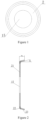
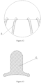
- a tube body support member 2 comprises a body 21; as an option, the body 21 can be of a disc type (shown in FIG. 1 ), a shape of Chinese character " *" (shown in FIG. 18 ), a chainring type, and a cross type; meanwhile, to facilitate the addition of a support shaft, a shaft hole 15 is provided in the middle of the body 21; the outer edge of the support ring is connected with a support portion 23 through a connecting portion 22; the outer edge of the support portion 23 is circular and it is adapted to the inner wall of the tube body 1.
- the outer edge of the body 21 is provided with the connecting portion 22, and one end of the connecting portion 22 away from the body 21 is provided with the support portion 23; the support portion 23 is inclined to a side away from the body 21; the angle ⁇ between the support portion 23 and the vertical plane is 90°-150°, and the distance d between the support portion 23 and the body 21 is greater than or equal to 5 mm; in this embodiment, the distance between the support portion 23 and the body 21 is 5 mm, and the angle between the support portion 23 and the vertical plane is 95°; as specific alternatives, the distance between the support portion 23 and the body 21 is 6 mm, 8 mm, 10 mm, etc., and the angle between the support portion 23 and the vertical plane can also be 100°, 105°, 120°, etc.; when the support portion 23 is subjected to a radial external force, the deformation of the connecting portion 22 drives the inclination angle of the support portion 23 to increase or decrease; the thickness of the connecting portion 22 is 3 mm-20 mm; specifically, the connecting portion 22 is
- first connecting portion 22 and the second connecting portion 22 can be chosen to be used, preferably an arc-shaped first connecting portion 22 with a radius of 5 mm; as specific options, the radius of the first connecting portion 22 can also be 2 mm, 8 mm, 15 mm etc.; when the tube body support member 2 is subjected to radial external forces (e.g., radially inward pressure, outward pulling force, etc.), the deformation of the connecting portion 22 drives the inclination angle of the support portion 23 to increase or decrease; this embodiment is mainly applied to the internal support of the tube body 1; the tube body support member 2 will be subjected to the radial pressure of the tube wall when it enters the tube body 1, thereby driving the inclination angle of the support portion 23 to decrease; at this time, the restoring stress will not be eliminated, and an elastic support will be formed under the restoring stress of the connecting portion 22; one aspect is that the diameter of the tube body support member 2 can be greater than the diameter of the inner cavity of the tube body 1 during design; after
- this embodiment provides a tube for making a roller, said tube being prepared from the tube body support member 2 described in any one of the above;
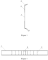
- the tube comprises a cylindrical tube body 1, wherein a plurality of tube body support members 2 according to any one of the above are arranged at intervals along the length direction of the tube body 1; during preparation, the tube body support members 2 are put into the tube body 1 from the two ends of the tube body 1 respectively; using the cross-section at the middle of the tube body 1 as a middle interface, the distance between the two tube body support members 2 adjacent to the middle interface is not greater than the distance between any two tube body support members 2; when in use, the position where the tube body 1 is most likely to undergo elastic deformation is the middle part of the tube body 1; the distance between the two tube body support members 2 adjacent to the middle interface not being greater than the distance between any two tube body support members 2, can increase the support force for the middle part of the tube body, and prevents the deformation of the middle part of the tube body effectively; at the same time as
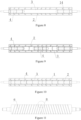
- This embodiment provides a roller body prepared from any one of the above-mentioned tubes for making a roller, as shown in Figures 6-15 , comprising any one of the above-mentioned tubes for making a roller.
- the support portions 23 on both sides of the middle interface are inclined towards the side away from the middle interface; following the inclination direction of the support portion 23, the frictional force can be reduced, which can facilitate putting the tube body support members 2 into the tube body 1; the elastic support force can facilitate the tube body support members 2 to enter the tube body 1 in a vertical state; further, the tube body support members 2 cannot move in the reverse direction because the support portion 23 is inclined, which can facilitate the tube body support members 2 to support the tube body 1 stably.
- the tube for making a roller of this embodiment may further comprise a first support shaft 3; the body 21 is provided with a shaft hole 15 that matches the first support shaft 3; the first support shaft 3 passes through shaft holes 15 of at least two bodies 21; the first support shaft 3 is a through shaft, or comprises a left half shaft and a right half shaft, or comprises a left half shaft, a right half shaft and an intermediate shaft; the first support shaft 3 connects the tube body support members 2 in series through the shaft holes 15, which can increase the support strength of the tube body 1 and prevent the tube body 1 from being deformed and bent when the tube is subjected to an axial pulling force; in order to further increase the support strength of the tube body 1 , it further comprises a second support shaft 4; the first support shaft 3 is of a hollow structure and a plurality of tube body support members 2 are arranged in the first support shaft 3; the tube body support members 2 arranged in the first support shaft 3 are provided with shaft holes 15 that match the second support shaft 4, and
- a spacer sleeve is provided outside the tube body 1; the spacer sleeve comprises a plurality of sleeves 51; a ring-shaped spacer 52 is arranged between adjacent sleeves 51; the inner diameters of the sleeves 51 and the ring-shaped spacer are slightly greater than the outer diameter of the tube body 1; the distance between the two ring-shaped spacers 52 is controlled by the spacer sleeve; the diameter difference between the ring-shaped spacers 52 and the spacer sleeve is 5-15 mm; it is mainly applied to the preparation of ironing machines for washing equipment; in specific applications, fastening sleeves 53 are used at both ends of the tube body 1 for fixing; the fastening sleeves 53 are threadedly connected to the tube body 1; it is applied to the guide rollers for separating the conveying belts; the function of the spacer sleeve is to prevent each belt from moving laterally.
- the tube body 1 comprises a base tube 11, the base tube 11 being covered with a stainless steel tube 12; the wall thickness of the tube body 1 is not less than 4 mm, or 5.5 mm, 6 mm, 6.5 mm can be selected, but generally not more than 10 mm; further, the stainless steel tube 12 is radially provided with a plurality of separating plates 54, and the separating plates 54 are fixedly connected with the stainless steel tube 12 or integrally formed with the stainless steel tube 12, e.g., the separating plates 54 can be corrugated separating plates 55 formed by extruding and bulging the surface of the stainless steel tube 12; the height of the corrugated separating plates 55 is 5-15 mm; the corrugated separating plates 55 and the stainless steel tube 12 are integrally formed without gaps, which can reduce the wear of the conveying belts; it is mainly applied to prepare guide rollers for separating the conveying belts, by which each belt does not move laterally.
- the surface of the tube body 1 is provided with a winding wire 6 having a left-handed and/or right-handed rotation direction, and the cross-section of the winding wire 6 has a T-shape (inverted T-shape) with a top surface having an arc shape; wherein the radius of the arc on the top surface is 10-125 mm, and the height of the winding wire 6 is 3-12 mm; it is used to prepare a expanding roller that has a function of expanding the fabric; on one hand, it can increase the contact surface of the fabric so that the fabric has more stressed surfaces during expanding, thereby improving the expanding effect; on the other hand, the contact surface between the bottom of the wire and the outer wall of the roller is large, so that the connection between the wire and the stainless steel outer tube is enhanced.
- T-shape inverted T-shape
- an outer sleeve 7 is sleeved on the outer side of the tube for making a roller, and the outer sleeve 7 is axially provided with a plurality of protrusions 71, and the top of the protrusions is arc-shaped;
- this kind of roller body is mainly applied to the cloth guide roller of water washing equipment; the design of the protrusions 71 can not only reduce the contact area between the fabric and the roller body, reduce the wear of the roller body to the fabric, but also improve the washing effect of the fabric, as the water-washing medium can flow and penetrate between the protrusions 71 of the roller body to penetrate and wash the fabric.
- both ends of the first support shaft 3 or the second support shaft 4 extend out of the tube for making a roller; if only a first support shaft 3 is arranged in the tube body 1, the parts of the first support shaft 3 that extend out of the tube for making a roller are used as shaft heads 13; if a second support shaft 4 is arranged inside the first support shaft 3, the parts of the second support shaft 4 that extend out of the tube for making a roller are used as shaft heads 13; or if there is no support shaft extending out of the left and right ends of the tube body 1, both ends of the tube for making a roller are provided with shaft heads 13; one end of the shaft head 13 extends out of the tube for making a roller, and at least three shaft flanges 14 are provided on the shaft head 13; the shaft flanges 14 are straight flanges, bowl
Landscapes
- Engineering & Computer Science (AREA)
- Textile Engineering (AREA)
- General Engineering & Computer Science (AREA)
- Mechanical Engineering (AREA)
- Rolls And Other Rotary Bodies (AREA)
- Rigid Pipes And Flexible Pipes (AREA)
- Supports For Pipes And Cables (AREA)
Claims (16)
- Rohr zum Herstellen einer Walze, umfassend:einen zylindrischen Rohrkörper (1), wobei in dem Rohrkörper (1) eine Vielzahl von Rohrkörperstützelementen (2) in Abständen entlang der Längsrichtung des Rohrkörpers (1) angeordnet sind;wobei das Rohrkörperstützelement (2) einen Körper (21) umfasst;wobei eine Außenkante des Körpers (21) mit einem Verbindungsabschnitt (22) verbunden ist und das andere Ende des Verbindungsabschnitts (22) mit einem Stützabschnitt (23) verbunden ist;wobei der Winkel zwischen dem Stützabschnitt (23) und einer horizontalen Ebene ein spitzer Winkel ist, und der Durchmesser des durch die Außenkante des Stützabschnitts (23) gebildeten Kreises größer ist als der Durchmesser des durch die Außenkante des Verbindungsabschnitts (22) gebildeten Kreises;eine erste Stützwelle (3); wobei der Körper (21) mit einem zu der ersten Stützwelle (3) passenden Wellenloch (15) versehen ist; wobei die erste Stützwelle (3) durch die Wellenlöcher (15) von zumindest zwei Körpern (21) verläuft;dadurch gekennzeichnet, dass es weiter umfasst:
eine zweite Stützwelle (4); wobei die erste Stützwelle (3) eine Hohlstruktur aufweist, und eine Vielzahl der Rohrkörperstützelemente (2) in der ersten Stützwelle (3) angeordnet sind; wobei die in der ersten Stützwelle (3) angeordneten Rohrkörperstützelemente (2) mit zu der zweiten Stützwelle (4) passenden Wellenlöchern (15) versehen sind und die zweite Stützwelle (4) durch die Wellenlöcher (15) von zumindest zwei Rohrkörperstützelementen (2) verläuft. - Rohr zum Herstellen einer Walze nach Anspruch 1, dadurch gekennzeichnet, dass bei Verwendung des Querschnitts in der Mitte des Rohrkörpers (1) als mittlere Schnittstelle der Abstand zwischen den beiden zu der mittleren Schnittstelle benachbarten Rohrkörperstützelementen (2) nicht größer ist als der Abstand zwischen zwei beliebigen Rohrkörperstützelementen (2).
- Rohr zum Herstellen einer Walze nach Anspruch 2, dadurch gekennzeichnet, dass bei den Rohrkörperstützelementen (2), welche sich auf derselben Seite der Zwischenschnittstelle befinden, ausgehend von der Zwischenschnittstelle bis zu einem Ende des Rohrkörpers (1) der Abstand zwischen den benachbarten Rohrkörperstützelementen (2) allmählich bis zu einer vorbestimmten Länge zunimmt und die benachbarten Rohrkörperstützelemente (2) dann in gleichen Abständen verteilt sind.
- Rohr zum Herstellen einer Walze nach Anspruch 1, dadurch gekennzeichnet, dass außerhalb des Rohrkörpers (1) eine Abstandshalterhülse bereitgestellt ist; wobei die Abstandshalterhülse eine Vielzahl von Hülsen (51) umfasst; wobei zwischen benachbarten Hülsen (51) ein ringförmiger Abstandshalter (52) angeordnet ist; wobei die Innendurchmesser der Hülsen (51) und des ringförmigen Abstandshalters (52) geringfügig größer sind als der Außendurchmesser des Rohrkörpers (1).
- Rohr zum Herstellen einer Walze nach Anspruch 1, dadurch gekennzeichnet, dass der Rohrkörper (1) ein Basisrohr (11) umfasst; wobei das Basisrohr (11) mit einem Edelstahlrohr (12) ummantelt ist, und die Wandstärke des Rohrkörpers (1) nicht weniger als 4 mm beträgt.
- Rohr zum Herstellen einer Walze nach einem der Ansprüche 1-5, dadurch gekennzeichnet, dass der Verbindungsabschnitt (22) ein erster Verbindungsabschnitt ist; wobei der erste Verbindungsabschnitt ein bogenförmiger Verbindungsabschnitt ist; wobei ein Ende des bogenförmigen Verbindungsabschnitts mit dem Körper (21) verbunden ist und das andere Ende mit dem Stützabschnitt (23) verbunden ist;
oder
ein zweiter Verbindungsabschnitt ist; wobei der zweite Verbindungsabschnitt zu einer von dem Körper (21) wegweisenden Seite geneigt ist, und wobei der Neigungswinkel des zweiten Verbindungsabschnitts kleiner ist als der Neigungswinkel des Stützabschnitts (23). - Rohr zum Herstellen einer Walze nach Anspruch 6, dadurch gekennzeichnet, dass der Radius des ersten Verbindungsabschnitts 2-15 mm beträgt.
- Rohr zum Herstellen einer Walze nach einem der Ansprüche 1-7, dadurch gekennzeichnet, dassder Abstand zwischen dem Stützabschnitt (23) und dem Körper (21) nicht weniger als 5 mm beträgt;
und/oderder Winkel zwischen dem Stützabschnitt (23) und einer vertikalen Ebene 90°-150° beträgt. - Rohr zum Herstellen einer Walze nach einem der Ansprüche 1-8, dadurch gekennzeichnet, dass die Dicke des Verbindungsabschnitts (22) 3 mm-20 mm beträgt.
- Walzenkörper, dadurch gekennzeichnet, dass er ein Rohr zum Herstellen einer Walze nach einem der Ansprüche 1-9 umfasst.
- Walzenkörper nach Anspruch 10, dadurch gekennzeichnet, dass beide Enden der ersten Stützwelle (3) oder der zweiten Stützwelle (4) aus dem Rohr zum Herstellen einer Walze herausragen;
oder
beide Enden des Rohrs zum Herstellen einer Walze mit Wellenköpfen (13) versehen sind; wobei ein Ende des Wellenkopfes (13) aus dem Rohr zum Herstellen einer Walze herausragt und an dem Wellenkopf (13) zumindest drei Wellenflansche (14) bereitgestellt sind; wobei die Außenkante der Wellenflansche (14) mit der Innenwand des Rohrkörpers (1) oder der Innenwand der Stützwelle verbunden ist. - Walzenkörper nach Anspruch 11, dadurch gekennzeichnet, dass die Wellenflansche (14) gerade Flansche, Schalenflansche oder die Rohrkörperstützelemente (2) sind.
- Walzenkörper nach Anspruch 5 und Anspruch 10, dadurch gekennzeichnet, dass das Edelstahlrohr (12) radial mit einer Vielzahl von Trennblechen (54) versehen ist, und die Trennbleche (54) fest mit dem Edelstahlrohr (12) verbunden oder einstückig mit dem Edelstahlrohr (12) gebildet sind.
- Walzenkörper nach Anspruch 10, dadurch gekennzeichnet, dass die Oberfläche des Rohrkörpers (1) mit einem Wickeldraht (6) versehen ist, welcher eine linksgängige und/oder rechtsgängige Drehrichtung aufweist, und der Querschnitt des Wickeldrahtes (6) eine T-Form mit einer bogenförmigen Oberseite aufweist.
- Walzenkörper nach Anspruch 10, dadurch gekennzeichnet, dass eine Außenhülse (7) auf die Außenseite des Rohrs zum Herstellen einer Walze geschoben wird, und die Außenhülse (7) axial mit einer Vielzahl von Vorsprüngen (71) versehen ist, und die Spitze der Vorsprünge (71) bogenförmig ist.
- Bügelmaschine, Legemaschine, Wäschetransporter, Faltmaschine oder Stapelmaschine, welche einen Walzenkörper nach einem der Ansprüche 10-15 verwendet.
Applications Claiming Priority (2)
| Application Number | Priority Date | Filing Date | Title |
|---|---|---|---|
| CN201910747638.4A CN110422677A (zh) | 2019-08-14 | 2019-08-14 | 一种管体支撑件、制辊用管、辊体和辊体的应用 |
| PCT/CN2020/101634 WO2021027461A1 (zh) | 2019-08-14 | 2020-07-13 | 一种管体支撑件、制辊用管、辊体和辊体的应用 |
Publications (3)
| Publication Number | Publication Date |
|---|---|
| EP4015688A1 EP4015688A1 (de) | 2022-06-22 |
| EP4015688A4 EP4015688A4 (de) | 2023-08-23 |
| EP4015688B1 true EP4015688B1 (de) | 2024-08-21 |
Family
ID=68416225
Family Applications (1)
| Application Number | Title | Priority Date | Filing Date |
|---|---|---|---|
| EP20853096.4A Active EP4015688B1 (de) | 2019-08-14 | 2020-07-13 | Rohr zur herstellung einer walze, walzenkörper und verwendung des walzenkörpers |
Country Status (6)
| Country | Link |
|---|---|
| EP (1) | EP4015688B1 (de) |
| JP (1) | JP7675442B2 (de) |
| KR (1) | KR102636991B1 (de) |
| CN (1) | CN110422677A (de) |
| ES (1) | ES2988385T3 (de) |
| WO (1) | WO2021027461A1 (de) |
Families Citing this family (6)
| Publication number | Priority date | Publication date | Assignee | Title |
|---|---|---|---|---|
| CN110422677A (zh) * | 2019-08-14 | 2019-11-08 | 山东广泰环保科技有限公司 | 一种管体支撑件、制辊用管、辊体和辊体的应用 |
| CN110626848B (zh) * | 2019-08-14 | 2024-05-03 | 山东广泰环保科技有限公司 | 一种复合管、制备装置、工艺、辊体和辊体的应用 |
| CN110606400A (zh) * | 2019-09-21 | 2019-12-24 | 江苏技成机械科技有限公司 | 一种隔板、隔带装置、导辊及导辊的应用 |
| CN211664397U (zh) * | 2019-11-29 | 2020-10-13 | 山东广泰环保科技有限公司 | 一种新型t型扩幅丝、辊体及辊体的应用 |
| CN110902506B (zh) * | 2019-11-29 | 2024-05-14 | 山东广泰环保科技有限公司 | 一种扩幅辊体绕丝设备、扩幅辊体和绕丝方法 |
| CN116447221A (zh) * | 2023-04-03 | 2023-07-18 | 山东广泰环保科技有限公司 | 一种辊体密封件、导辊及机械设备 |
Family Cites Families (23)
| Publication number | Priority date | Publication date | Assignee | Title |
|---|---|---|---|---|
| GB1096994A (en) * | 1964-01-23 | 1967-12-29 | Courtaulds Ltd | Yarn package support |
| FR1539707A (fr) * | 1967-06-13 | 1968-09-20 | Scragg & Sons | Support pour tube, destiné notamment à équiper les machines de traitement de fil |
| DE3903161A1 (de) * | 1989-02-03 | 1990-08-09 | Helmuth Schmoock | Breitstreckenwalze |
| JPH05132211A (ja) * | 1991-11-07 | 1993-05-28 | Ricoh Co Ltd | 紙搬送用ロ−ラ |
| FR2696166B1 (fr) * | 1992-09-28 | 1994-11-18 | Escher Wyss Ag | Cylindre de guidage d'une bande. |
| JPH0797109A (ja) * | 1993-09-29 | 1995-04-11 | Sando Iron Works Co Ltd | 布帛移送用のスリップレスロール |
| KR100925262B1 (ko) * | 2002-12-24 | 2009-11-05 | 정명규 | 직물건조용 텐터건조기의 가이드 롤러 |
| DE10305699A1 (de) * | 2003-02-12 | 2004-08-26 | Kampf Gmbh & Co Maschinenfabrik | Walze für eine Wickelmaschine |
| JP2005306549A (ja) | 2004-04-21 | 2005-11-04 | Akatsuki Kinzoku Kogyo:Kk | 搬送ローラ |
| JP2007039241A (ja) | 2005-07-29 | 2007-02-15 | Dairii International:Kk | 溝付きスリーブウェブスプレッダーロール |
| JP2007047321A (ja) * | 2005-08-08 | 2007-02-22 | Ricoh Co Ltd | ローラ芯金及びその製造方法、定着ローラ、定着装置、及び、それを有する画像形成装置 |
| JP6551237B2 (ja) | 2014-10-31 | 2019-07-31 | 東レ株式会社 | 溝付ローラー、ならびにこれを用いたプラスチックフィルムの製造装置および製造方法 |
| CN204453992U (zh) | 2015-01-01 | 2015-07-08 | 宁波卓越印务有限公司 | 一种印刷机展平辊 |
| CN205775317U (zh) * | 2016-07-05 | 2016-12-07 | 山东广泰环保科技有限公司 | 一种超长导辊结构 |
| CN205839435U (zh) * | 2016-07-05 | 2016-12-28 | 山东广泰环保科技有限公司 | 一种烫平机用隔带辊 |
| CN206327972U (zh) | 2016-12-14 | 2017-07-14 | 淄博朗达复合材料有限公司 | 高刚碳纤维复合材料导辊 |
| CN106429590A (zh) | 2016-12-14 | 2017-02-22 | 淄博朗达复合材料有限公司 | 高刚碳纤维复合材料导辊 |
| CN206873104U (zh) * | 2017-05-10 | 2018-01-12 | 东莞市金银丰机械实业有限公司 | 轧辊 |
| DE102017012009A1 (de) | 2017-12-22 | 2019-06-27 | Texmag Gmbh Vertriebsgesellschaft | Segmentwalze |
| CN305596712S (de) * | 2019-08-14 | 2020-02-07 | ||
| CN211225729U (zh) * | 2019-08-14 | 2020-08-11 | 山东广泰环保科技有限公司 | 一种管体支撑件、制辊用管、辊体和机械设备 |
| CN110422677A (zh) | 2019-08-14 | 2019-11-08 | 山东广泰环保科技有限公司 | 一种管体支撑件、制辊用管、辊体和辊体的应用 |
| CN110606400A (zh) | 2019-09-21 | 2019-12-24 | 江苏技成机械科技有限公司 | 一种隔板、隔带装置、导辊及导辊的应用 |
-
2019
- 2019-08-14 CN CN201910747638.4A patent/CN110422677A/zh active Pending
-
2020
- 2020-07-13 KR KR1020217025110A patent/KR102636991B1/ko active Active
- 2020-07-13 ES ES20853096T patent/ES2988385T3/es active Active
- 2020-07-13 WO PCT/CN2020/101634 patent/WO2021027461A1/zh not_active Ceased
- 2020-07-13 JP JP2021567882A patent/JP7675442B2/ja active Active
- 2020-07-13 EP EP20853096.4A patent/EP4015688B1/de active Active
Also Published As
| Publication number | Publication date |
|---|---|
| WO2021027461A1 (zh) | 2021-02-18 |
| KR102636991B1 (ko) | 2024-02-14 |
| KR20210111303A (ko) | 2021-09-10 |
| CN110422677A (zh) | 2019-11-08 |
| JP2022544890A (ja) | 2022-10-24 |
| EP4015688A1 (de) | 2022-06-22 |
| JP7675442B2 (ja) | 2025-05-13 |
| EP4015688A4 (de) | 2023-08-23 |
| ES2988385T3 (es) | 2024-11-20 |
Similar Documents
| Publication | Publication Date | Title |
|---|---|---|
| EP4015688B1 (de) | Rohr zur herstellung einer walze, walzenkörper und verwendung des walzenkörpers | |
| CN211225729U (zh) | 一种管体支撑件、制辊用管、辊体和机械设备 | |
| KR19980086964A (ko) | 소형 중간 주름 형성 롤을 갖는 개량된 편면 페이서 | |
| CN111470284A (zh) | 一种锥形辊筒 | |
| KR20220088048A (ko) | 부분 교체형 고무롤 | |
| JP7582692B2 (ja) | 離間板、ベルト離間装置、ガイドローラ及びガイドローラの適用 | |
| CN210619834U (zh) | 一种dty加弹机的原丝架防脱挂丝杆 | |
| EP3057898B1 (de) | Wickelstange für bahnmaterialrollen und wickelmaschine mit dieser stange | |
| CN218880308U (zh) | 布料染色机 | |
| CN212849996U (zh) | 一种洗衣机电机定子铁芯 | |
| CN214625127U (zh) | 一种防极耳翻折的过辊装置 | |
| CN215438391U (zh) | 一种带式输送机的摊辊装置 | |
| CN219585423U (zh) | 纸芯夹头及复卷机 | |
| EP1967474B1 (de) | Ausbreitwalze für Stoffbahnen | |
| CN217947145U (zh) | 涂改带的带芯圈 | |
| CN222169453U (zh) | 一种电机滚筒与端盖的连接结构 | |
| CN206494572U (zh) | 槽筒式络筒机机械防叠装置 | |
| CN218838640U (zh) | 弯曲辊 | |
| CN216072308U (zh) | 一种装饰纸收卷用防跑偏装置 | |
| CN221419910U (zh) | 一种钢辊棒 | |
| CN121204873A (zh) | 纺织机的气圈控制环和制作方法 | |
| CN218644666U (zh) | 一种双折边控油圆锥轴承保持器 | |
| CN210959924U (zh) | 可调阻尼的猫跑步机 | |
| CN223225572U (zh) | 一种调节灵活的芳纶纱线卷绕筒 | |
| CN215438389U (zh) | 一种带式输送机的摊辊装置 |
Legal Events
| Date | Code | Title | Description |
|---|---|---|---|
| STAA | Information on the status of an ep patent application or granted ep patent |
Free format text: STATUS: THE INTERNATIONAL PUBLICATION HAS BEEN MADE |
|
| PUAI | Public reference made under article 153(3) epc to a published international application that has entered the european phase |
Free format text: ORIGINAL CODE: 0009012 |
|
| STAA | Information on the status of an ep patent application or granted ep patent |
Free format text: STATUS: REQUEST FOR EXAMINATION WAS MADE |
|
| 17P | Request for examination filed |
Effective date: 20220309 |
|
| AK | Designated contracting states |
Kind code of ref document: A1 Designated state(s): AL AT BE BG CH CY CZ DE DK EE ES FI FR GB GR HR HU IE IS IT LI LT LU LV MC MK MT NL NO PL PT RO RS SE SI SK SM TR |
|
| DAV | Request for validation of the european patent (deleted) | ||
| DAX | Request for extension of the european patent (deleted) | ||
| A4 | Supplementary search report drawn up and despatched |
Effective date: 20230724 |
|
| RIC1 | Information provided on ipc code assigned before grant |
Ipc: B65H 27/00 20060101ALI20230718BHEP Ipc: F16C 13/00 20060101ALI20230718BHEP Ipc: B65H 75/24 20060101ALI20230718BHEP Ipc: D06B 15/02 20060101ALI20230718BHEP Ipc: D06B 23/02 20060101ALI20230718BHEP Ipc: D03D 49/20 20060101AFI20230718BHEP |
|
| GRAP | Despatch of communication of intention to grant a patent |
Free format text: ORIGINAL CODE: EPIDOSNIGR1 |
|
| STAA | Information on the status of an ep patent application or granted ep patent |
Free format text: STATUS: GRANT OF PATENT IS INTENDED |
|
| INTG | Intention to grant announced |
Effective date: 20240419 |
|
| GRAS | Grant fee paid |
Free format text: ORIGINAL CODE: EPIDOSNIGR3 |
|
| GRAA | (expected) grant |
Free format text: ORIGINAL CODE: 0009210 |
|
| STAA | Information on the status of an ep patent application or granted ep patent |
Free format text: STATUS: THE PATENT HAS BEEN GRANTED |
|
| AK | Designated contracting states |
Kind code of ref document: B1 Designated state(s): AL AT BE BG CH CY CZ DE DK EE ES FI FR GB GR HR HU IE IS IT LI LT LU LV MC MK MT NL NO PL PT RO RS SE SI SK SM TR |
|
| REG | Reference to a national code |
Ref country code: GB Ref legal event code: FG4D |
|
| REG | Reference to a national code |
Ref country code: CH Ref legal event code: EP |
|
| REG | Reference to a national code |
Ref country code: IE Ref legal event code: FG4D Ref country code: NL Ref legal event code: FP |
|
| REG | Reference to a national code |
Ref country code: DE Ref legal event code: R096 Ref document number: 602020036399 Country of ref document: DE |
|
| REG | Reference to a national code |
Ref country code: ES Ref legal event code: FG2A Ref document number: 2988385 Country of ref document: ES Kind code of ref document: T3 Effective date: 20241120 |
|
| REG | Reference to a national code |
Ref country code: LT Ref legal event code: MG9D |
|
| PG25 | Lapsed in a contracting state [announced via postgrant information from national office to epo] |
Ref country code: NO Free format text: LAPSE BECAUSE OF FAILURE TO SUBMIT A TRANSLATION OF THE DESCRIPTION OR TO PAY THE FEE WITHIN THE PRESCRIBED TIME-LIMIT Effective date: 20241121 |
|
| REG | Reference to a national code |
Ref country code: AT Ref legal event code: MK05 Ref document number: 1715563 Country of ref document: AT Kind code of ref document: T Effective date: 20240821 |
|
| PG25 | Lapsed in a contracting state [announced via postgrant information from national office to epo] |
Ref country code: FI Free format text: LAPSE BECAUSE OF FAILURE TO SUBMIT A TRANSLATION OF THE DESCRIPTION OR TO PAY THE FEE WITHIN THE PRESCRIBED TIME-LIMIT Effective date: 20240821 Ref country code: PT Free format text: LAPSE BECAUSE OF FAILURE TO SUBMIT A TRANSLATION OF THE DESCRIPTION OR TO PAY THE FEE WITHIN THE PRESCRIBED TIME-LIMIT Effective date: 20241223 Ref country code: GR Free format text: LAPSE BECAUSE OF FAILURE TO SUBMIT A TRANSLATION OF THE DESCRIPTION OR TO PAY THE FEE WITHIN THE PRESCRIBED TIME-LIMIT Effective date: 20241122 Ref country code: PL Free format text: LAPSE BECAUSE OF FAILURE TO SUBMIT A TRANSLATION OF THE DESCRIPTION OR TO PAY THE FEE WITHIN THE PRESCRIBED TIME-LIMIT Effective date: 20240821 |
|
| PG25 | Lapsed in a contracting state [announced via postgrant information from national office to epo] |
Ref country code: BG Free format text: LAPSE BECAUSE OF FAILURE TO SUBMIT A TRANSLATION OF THE DESCRIPTION OR TO PAY THE FEE WITHIN THE PRESCRIBED TIME-LIMIT Effective date: 20240821 |
|
| PG25 | Lapsed in a contracting state [announced via postgrant information from national office to epo] |
Ref country code: LV Free format text: LAPSE BECAUSE OF FAILURE TO SUBMIT A TRANSLATION OF THE DESCRIPTION OR TO PAY THE FEE WITHIN THE PRESCRIBED TIME-LIMIT Effective date: 20240821 |
|
| PG25 | Lapsed in a contracting state [announced via postgrant information from national office to epo] |
Ref country code: IS Free format text: LAPSE BECAUSE OF FAILURE TO SUBMIT A TRANSLATION OF THE DESCRIPTION OR TO PAY THE FEE WITHIN THE PRESCRIBED TIME-LIMIT Effective date: 20241221 Ref country code: AT Free format text: LAPSE BECAUSE OF FAILURE TO SUBMIT A TRANSLATION OF THE DESCRIPTION OR TO PAY THE FEE WITHIN THE PRESCRIBED TIME-LIMIT Effective date: 20240821 |
|
| PG25 | Lapsed in a contracting state [announced via postgrant information from national office to epo] |
Ref country code: HR Free format text: LAPSE BECAUSE OF FAILURE TO SUBMIT A TRANSLATION OF THE DESCRIPTION OR TO PAY THE FEE WITHIN THE PRESCRIBED TIME-LIMIT Effective date: 20240821 |
|
| PG25 | Lapsed in a contracting state [announced via postgrant information from national office to epo] |
Ref country code: RS Free format text: LAPSE BECAUSE OF FAILURE TO SUBMIT A TRANSLATION OF THE DESCRIPTION OR TO PAY THE FEE WITHIN THE PRESCRIBED TIME-LIMIT Effective date: 20241121 |
|
| PG25 | Lapsed in a contracting state [announced via postgrant information from national office to epo] |
Ref country code: RS Free format text: LAPSE BECAUSE OF FAILURE TO SUBMIT A TRANSLATION OF THE DESCRIPTION OR TO PAY THE FEE WITHIN THE PRESCRIBED TIME-LIMIT Effective date: 20241121 Ref country code: PT Free format text: LAPSE BECAUSE OF FAILURE TO SUBMIT A TRANSLATION OF THE DESCRIPTION OR TO PAY THE FEE WITHIN THE PRESCRIBED TIME-LIMIT Effective date: 20241223 Ref country code: PL Free format text: LAPSE BECAUSE OF FAILURE TO SUBMIT A TRANSLATION OF THE DESCRIPTION OR TO PAY THE FEE WITHIN THE PRESCRIBED TIME-LIMIT Effective date: 20240821 Ref country code: NO Free format text: LAPSE BECAUSE OF FAILURE TO SUBMIT A TRANSLATION OF THE DESCRIPTION OR TO PAY THE FEE WITHIN THE PRESCRIBED TIME-LIMIT Effective date: 20241121 Ref country code: LV Free format text: LAPSE BECAUSE OF FAILURE TO SUBMIT A TRANSLATION OF THE DESCRIPTION OR TO PAY THE FEE WITHIN THE PRESCRIBED TIME-LIMIT Effective date: 20240821 Ref country code: IS Free format text: LAPSE BECAUSE OF FAILURE TO SUBMIT A TRANSLATION OF THE DESCRIPTION OR TO PAY THE FEE WITHIN THE PRESCRIBED TIME-LIMIT Effective date: 20241221 Ref country code: HR Free format text: LAPSE BECAUSE OF FAILURE TO SUBMIT A TRANSLATION OF THE DESCRIPTION OR TO PAY THE FEE WITHIN THE PRESCRIBED TIME-LIMIT Effective date: 20240821 Ref country code: GR Free format text: LAPSE BECAUSE OF FAILURE TO SUBMIT A TRANSLATION OF THE DESCRIPTION OR TO PAY THE FEE WITHIN THE PRESCRIBED TIME-LIMIT Effective date: 20241122 Ref country code: FI Free format text: LAPSE BECAUSE OF FAILURE TO SUBMIT A TRANSLATION OF THE DESCRIPTION OR TO PAY THE FEE WITHIN THE PRESCRIBED TIME-LIMIT Effective date: 20240821 Ref country code: BG Free format text: LAPSE BECAUSE OF FAILURE TO SUBMIT A TRANSLATION OF THE DESCRIPTION OR TO PAY THE FEE WITHIN THE PRESCRIBED TIME-LIMIT Effective date: 20240821 Ref country code: AT Free format text: LAPSE BECAUSE OF FAILURE TO SUBMIT A TRANSLATION OF THE DESCRIPTION OR TO PAY THE FEE WITHIN THE PRESCRIBED TIME-LIMIT Effective date: 20240821 |
|
| PG25 | Lapsed in a contracting state [announced via postgrant information from national office to epo] |
Ref country code: RO Free format text: LAPSE BECAUSE OF FAILURE TO SUBMIT A TRANSLATION OF THE DESCRIPTION OR TO PAY THE FEE WITHIN THE PRESCRIBED TIME-LIMIT Effective date: 20240821 Ref country code: SM Free format text: LAPSE BECAUSE OF FAILURE TO SUBMIT A TRANSLATION OF THE DESCRIPTION OR TO PAY THE FEE WITHIN THE PRESCRIBED TIME-LIMIT Effective date: 20240821 Ref country code: DK Free format text: LAPSE BECAUSE OF FAILURE TO SUBMIT A TRANSLATION OF THE DESCRIPTION OR TO PAY THE FEE WITHIN THE PRESCRIBED TIME-LIMIT Effective date: 20240821 |
|
| PG25 | Lapsed in a contracting state [announced via postgrant information from national office to epo] |
Ref country code: EE Free format text: LAPSE BECAUSE OF FAILURE TO SUBMIT A TRANSLATION OF THE DESCRIPTION OR TO PAY THE FEE WITHIN THE PRESCRIBED TIME-LIMIT Effective date: 20240821 |
|
| PG25 | Lapsed in a contracting state [announced via postgrant information from national office to epo] |
Ref country code: CZ Free format text: LAPSE BECAUSE OF FAILURE TO SUBMIT A TRANSLATION OF THE DESCRIPTION OR TO PAY THE FEE WITHIN THE PRESCRIBED TIME-LIMIT Effective date: 20240821 |
|
| PG25 | Lapsed in a contracting state [announced via postgrant information from national office to epo] |
Ref country code: SK Free format text: LAPSE BECAUSE OF FAILURE TO SUBMIT A TRANSLATION OF THE DESCRIPTION OR TO PAY THE FEE WITHIN THE PRESCRIBED TIME-LIMIT Effective date: 20240821 |
|
| REG | Reference to a national code |
Ref country code: DE Ref legal event code: R097 Ref document number: 602020036399 Country of ref document: DE |
|
| PLBE | No opposition filed within time limit |
Free format text: ORIGINAL CODE: 0009261 |
|
| STAA | Information on the status of an ep patent application or granted ep patent |
Free format text: STATUS: NO OPPOSITION FILED WITHIN TIME LIMIT |
|
| PGFP | Annual fee paid to national office [announced via postgrant information from national office to epo] |
Ref country code: BE Payment date: 20250509 Year of fee payment: 6 |
|
| 26N | No opposition filed |
Effective date: 20250522 |
|
| PGFP | Annual fee paid to national office [announced via postgrant information from national office to epo] |
Ref country code: NL Payment date: 20250723 Year of fee payment: 6 |
|
| PG25 | Lapsed in a contracting state [announced via postgrant information from national office to epo] |
Ref country code: SE Free format text: LAPSE BECAUSE OF FAILURE TO SUBMIT A TRANSLATION OF THE DESCRIPTION OR TO PAY THE FEE WITHIN THE PRESCRIBED TIME-LIMIT Effective date: 20240821 |
|
| PGFP | Annual fee paid to national office [announced via postgrant information from national office to epo] |
Ref country code: ES Payment date: 20250819 Year of fee payment: 6 |
|
| PGFP | Annual fee paid to national office [announced via postgrant information from national office to epo] |
Ref country code: DE Payment date: 20250508 Year of fee payment: 6 |
|
| PGFP | Annual fee paid to national office [announced via postgrant information from national office to epo] |
Ref country code: IT Payment date: 20250731 Year of fee payment: 6 Ref country code: TR Payment date: 20250707 Year of fee payment: 6 |
|
| PGFP | Annual fee paid to national office [announced via postgrant information from national office to epo] |
Ref country code: CH Payment date: 20250801 Year of fee payment: 6 |
|
| PG25 | Lapsed in a contracting state [announced via postgrant information from national office to epo] |
Ref country code: LU Free format text: LAPSE BECAUSE OF NON-PAYMENT OF DUE FEES Effective date: 20250713 |
|
| GBPC | Gb: european patent ceased through non-payment of renewal fee |
Effective date: 20250713 |
|
| PG25 | Lapsed in a contracting state [announced via postgrant information from national office to epo] |
Ref country code: GB Free format text: LAPSE BECAUSE OF NON-PAYMENT OF DUE FEES Effective date: 20250713 |
|
| PG25 | Lapsed in a contracting state [announced via postgrant information from national office to epo] |
Ref country code: FR Free format text: LAPSE BECAUSE OF NON-PAYMENT OF DUE FEES Effective date: 20250731 |