EP4015085A1 - Dispositif de concassage des corps plats en fibre composite - Google Patents
Dispositif de concassage des corps plats en fibre composite Download PDFInfo
- Publication number
- EP4015085A1 EP4015085A1 EP20215398.7A EP20215398A EP4015085A1 EP 4015085 A1 EP4015085 A1 EP 4015085A1 EP 20215398 A EP20215398 A EP 20215398A EP 4015085 A1 EP4015085 A1 EP 4015085A1
- Authority
- EP
- European Patent Office
- Prior art keywords
- roller
- feed
- crushing
- crushing roller
- outer peripheral
- Prior art date
- Legal status (The legal status is an assumption and is not a legal conclusion. Google has not performed a legal analysis and makes no representation as to the accuracy of the status listed.)
- Pending
Links
Images


Classifications
-
- B—PERFORMING OPERATIONS; TRANSPORTING
- B02—CRUSHING, PULVERISING, OR DISINTEGRATING; PREPARATORY TREATMENT OF GRAIN FOR MILLING
- B02C—CRUSHING, PULVERISING, OR DISINTEGRATING IN GENERAL; MILLING GRAIN
- B02C4/00—Crushing or disintegrating by roller mills
- B02C4/10—Crushing or disintegrating by roller mills with a roller co-operating with a stationary member
-
- B—PERFORMING OPERATIONS; TRANSPORTING
- B02—CRUSHING, PULVERISING, OR DISINTEGRATING; PREPARATORY TREATMENT OF GRAIN FOR MILLING
- B02C—CRUSHING, PULVERISING, OR DISINTEGRATING IN GENERAL; MILLING GRAIN
- B02C4/00—Crushing or disintegrating by roller mills
- B02C4/02—Crushing or disintegrating by roller mills with two or more rollers
-
- B—PERFORMING OPERATIONS; TRANSPORTING
- B02—CRUSHING, PULVERISING, OR DISINTEGRATING; PREPARATORY TREATMENT OF GRAIN FOR MILLING
- B02C—CRUSHING, PULVERISING, OR DISINTEGRATING IN GENERAL; MILLING GRAIN
- B02C4/00—Crushing or disintegrating by roller mills
- B02C4/28—Details
- B02C4/286—Feeding devices
-
- B—PERFORMING OPERATIONS; TRANSPORTING
- B29—WORKING OF PLASTICS; WORKING OF SUBSTANCES IN A PLASTIC STATE IN GENERAL
- B29B—PREPARATION OR PRETREATMENT OF THE MATERIAL TO BE SHAPED; MAKING GRANULES OR PREFORMS; RECOVERY OF PLASTICS OR OTHER CONSTITUENTS OF WASTE MATERIAL CONTAINING PLASTICS
- B29B17/00—Recovery of plastics or other constituents of waste material containing plastics
- B29B17/04—Disintegrating plastics, e.g. by milling
- B29B2017/0424—Specific disintegrating techniques; devices therefor
- B29B2017/0476—Cutting or tearing members, e.g. spiked or toothed cylinders or intermeshing rollers
-
- B—PERFORMING OPERATIONS; TRANSPORTING
- B29—WORKING OF PLASTICS; WORKING OF SUBSTANCES IN A PLASTIC STATE IN GENERAL
- B29K—INDEXING SCHEME ASSOCIATED WITH SUBCLASSES B29B, B29C OR B29D, RELATING TO MOULDING MATERIALS OR TO MATERIALS FOR MOULDS, REINFORCEMENTS, FILLERS OR PREFORMED PARTS, e.g. INSERTS
- B29K2105/00—Condition, form or state of moulded material or of the material to be shaped
- B29K2105/06—Condition, form or state of moulded material or of the material to be shaped containing reinforcements, fillers or inserts
- B29K2105/08—Condition, form or state of moulded material or of the material to be shaped containing reinforcements, fillers or inserts of continuous length, e.g. cords, rovings, mats, fabrics, strands or yarns
-
- B—PERFORMING OPERATIONS; TRANSPORTING
- B29—WORKING OF PLASTICS; WORKING OF SUBSTANCES IN A PLASTIC STATE IN GENERAL
- B29L—INDEXING SCHEME ASSOCIATED WITH SUBCLASS B29C, RELATING TO PARTICULAR ARTICLES
- B29L2007/00—Flat articles, e.g. films or sheets
- B29L2007/002—Panels; Plates; Sheets
-
- Y—GENERAL TAGGING OF NEW TECHNOLOGICAL DEVELOPMENTS; GENERAL TAGGING OF CROSS-SECTIONAL TECHNOLOGIES SPANNING OVER SEVERAL SECTIONS OF THE IPC; TECHNICAL SUBJECTS COVERED BY FORMER USPC CROSS-REFERENCE ART COLLECTIONS [XRACs] AND DIGESTS
- Y02—TECHNOLOGIES OR APPLICATIONS FOR MITIGATION OR ADAPTATION AGAINST CLIMATE CHANGE
- Y02W—CLIMATE CHANGE MITIGATION TECHNOLOGIES RELATED TO WASTEWATER TREATMENT OR WASTE MANAGEMENT
- Y02W30/00—Technologies for solid waste management
- Y02W30/50—Reuse, recycling or recovery technologies
- Y02W30/52—Mechanical processing of waste for the recovery of materials, e.g. crushing, shredding, separation or disassembly
-
- Y—GENERAL TAGGING OF NEW TECHNOLOGICAL DEVELOPMENTS; GENERAL TAGGING OF CROSS-SECTIONAL TECHNOLOGIES SPANNING OVER SEVERAL SECTIONS OF THE IPC; TECHNICAL SUBJECTS COVERED BY FORMER USPC CROSS-REFERENCE ART COLLECTIONS [XRACs] AND DIGESTS
- Y02—TECHNOLOGIES OR APPLICATIONS FOR MITIGATION OR ADAPTATION AGAINST CLIMATE CHANGE
- Y02W—CLIMATE CHANGE MITIGATION TECHNOLOGIES RELATED TO WASTEWATER TREATMENT OR WASTE MANAGEMENT
- Y02W30/00—Technologies for solid waste management
- Y02W30/50—Reuse, recycling or recovery technologies
- Y02W30/62—Plastics recycling; Rubber recycling
Definitions
- the invention relates to a device for crushing flat bodies made of fiber composite material, with a rotatingly driven crushing roller with which the flat bodies can be brought into contact and which is designed to break up the flat bodies in contact with the outer peripheral surface of the crushing roller.
- Fibre-reinforced composites often form two-dimensional bodies, for example for rotors of wind turbines, boat hulls, sports equipment, machine housings, garden pond inserts, calf pens and the like.
- they are first sawed or cut into suitable transportable lengths in order to create sheets of a size that can be fed to an appropriate device for shredding the sheets, for example with transverse dimensions of 0.5 m up to 3 m or with main dimensions of, for example, 0.5 m to 5 m.
- the difficulty in comminuting planar bodies made of fiber composite material usually arises from the fact that the fiber content, ie for example glass fiber or carbon fibre, has an abrasive effect on the cutting tools of such a device for comminuting planar bodies.
- the service lives of cutting blades, the active tool parts of a shredder, a punching device for the shear cut and the like are often very short.
- the energy requirement for operating such devices is very high, since planar bodies made of fiber composite material generally have high strength, so that the comminution of planar bodies of this type generally requires high forces.
- the WO 93/05883 A1 describes the comminution of fiber composite materials using a hammer mill, and then the fibers are further separated from the matrix material, for example by means of a sieve and by means of an air stream.
- Querstromzerspanern for crushing fiber composites is known, such as in DE 20 2015 104 540 U1 described.
- Such Querstromzerspaner which are usually based on the principle of a rotating chain and crushed the sheets in a closed space, are very energy-intensive in their operation and the nature and size of the output products from the shredded sheets of fiber composite material is not selectively adjustable or this be able not be removed in an intermediate size formed.
- the JP 2012-091 134 A discloses a device for crushing planar bodies from the field of electrical engineering materials, in particular silicon, with crushing rollers driven in counter-rotating rotation, between which a crushing gap is formed and into which the planar bodies are introduced, as a result of which the planar bodies come into contact with the outer peripheral surfaces of the crushing rollers from one another break independent individual fragments.
- the complete separation of the fragments from one another between two crushing rollers driven in opposite directions is not sufficiently successful if the fiber content in a fiber composite material still holds the fragments together, so that a subsequent process or at least a second stage of two crushing rollers driven in opposite directions is necessary.
- the aim is that the crushed material can be provided in fragments that are no longer connected, without a subsequent process becoming necessary.
- the fragments should be a few millimeters or centimeters in size so that they can be reused.
- Conventional processes use cutting elements acting on the fiber composite materials in a manner known per se, which through contact with the fiber portion, especially fiberglass or carbon fiber, wear out in a short time.
- a breaking principle between two rollers is used, but this does not allow for the complete separation of the fragments, which are no longer attached to one another via their fiber content, in a single, closed process, and subsequent processes with separate process structures are necessary.
- the object of the invention is the further development of a device for comminuting flat bodies made of fiber composite material and the creation of a corresponding method for operating such a device, the device should have the longest possible service life of the active tools and the breaking result should consist of isolated fragments as far as possible.
- the device can be operated with a low energy consumption.
- the device should be designed in such a way that the shape, size and properties of the starting product can be selected from the comminuted flat bodies made of fiber composite material, in particular in order to supply the output products with further use.
- a feed device is provided with a feed surface formed on a feed element and is set up to move the planar bodies along the feed surface to advance the snapping roll to interact with the outer peripheral surface of the snapping roll, the feeding surface being inclined at an angle to a tangent of the outer peripheral surface or perpendicular to the tangent in the peripheral position of feeding.
- the device according to the invention thus enables planar bodies made of fiber composite material to be crushed by a process that is similar to rasping off the planar body, and breaking processes are initiated at the front edge of the planar body, which are based on tension between the outer peripheral surface of the crushing roller and the feed surface of the feed device.
- the feed surface is preferably, but not restrictively, designed as a flat surface and forms a kind of chute, via which the sheets are brought up to the crushing roller.
- the feeding surface is formed on a feeding member, and the feeding member is a central part of the feeding device.
- the flat body is preferably, but not restrictively, designed as a flat body, and in this respect it can also lie flat against the feed surface of the feed element. If the sheet is driven forward with the front edge first in the direction of the crushing roller, the rasping process can be initiated with appropriate equipment on the outer peripheral surface of the crushing roller, the tangent to the outer peripheral surface at the position at which the sheet is fed to the outer peripheral surface, an angle to the extent of the sheet which is greater than 20°, preferably greater than 50°, preferably greater than 60°, and most preferably greater than 70°.
- planar body is preferably guided approximately perpendicularly onto the outer peripheral surface of the crushing roller, and components of the planar body are broken away by the rasping process approximately perpendicularly to the plane of extent of the planar body.
- a sluggish feed against the crushing roller should be preferred to a stabbing feed.
- the device developed according to the invention for comminuting flat bodies made of fiber composite material has the advantage that the flat bodies are no longer fed between two crushing rollers and thus tangentially to their outer peripheral surfaces, since tangential feeding often results in the problem that in pure crushing processes the fiber component of the fiber composite material is not completely severed and that the individual fragments are still held together. This problem is significantly reduced by having the direction of movement of the sheet toward the point of tangency by guiding the sheet approximately perpendicularly toward the outer peripheral surface of the snapping roll.
- An advantageous embodiment of the device according to the invention has a crushing roller with crushing elements protruding on its outer peripheral surface.
- the breaking elements can produce a break in the planar bodies in the area of the leading edge.
- the breaking elements have no cutting edges that would trigger a cutting process in the surface body.
- the crushing elements are bluntly formed elements protruding from the surface of the crushing roller which, when they engage the leading edge of the sheet, produce a fracture therein which occurs based on a maximum breaking stress being exceeded.
- there is no shear cut but only fragments are detached from the front edge of the surface body, which are broken off laterally to the plane of extension of the feed element and the feed surface with the surface body resting on it.
- due to the freely occurring fracture surfaces there is also no shearing cut, so that the crushing elements only carry out a breaking process in the Produce sheets, and thereby a minimal to no wear of the crushing elements can be used to advantage.
- the crushing roller is rotated in a direction of rotation oriented such that the crushing elements, upon engagement with the leading edge of the sheet, press the sheet onto the leading, roller-side end of the feed surface of the feed element. Only in this way is a necessary break produced in the front edge of the sheet, which is based on a mechanical stress produced between the crushing elements on the one hand and the feed surface of the feed element of the feed device on the other hand.
- the sheet is consequently clamped between the breaking element and the feed surface of the feed element until finally the desired break occurs in the sheet.
- a feed drive which is designed and set up to act on the outer peripheral surface of the crushing roller in order to drive it forward.
- the feed drive can be operated with a controller in such a way that the flat body is fed against the crushing roller at an optimal feed rate. Due to the resulting crushing forces, which also act from the crushing roller in the direction of extension in the flat body, a forced feed of the flat body against the crushing roller is advantageous, which is formed by the feed drive.
- the feed drive can be controlled with the control device in such a way that the surface body is guided against the crushing roller at an optimal speed, so that the desired crushing result is produced.
- the feed drive is preferably designed with a drive motor which can be operated independently of the drive motor of the crushing roller.
- the feed drive for contact with the sheet has a Conveyor roller on, and the conveyor roller is driven by the drive motor.
- a pair of conveyor rollers can also be provided, wherein a conveyor roller of the pair of conveyor rollers can be arranged integrated in the feed element, and a section of the conveyor roller protrudes, for example, from the feed surface of the feed device.
- the feed roller has a structured surface such that it can generate a movement of the surface body in its extension direction with a pressing force against the surface body, in particular against the outer peripheral surface of the crushing roller.
- the conveying roller is arranged at a distance above the feed surface, forming a conveying gap, so that the planar bodies to be comminuted can be entered into the gap.
- the conveyor roller rotates at an outer peripheral speed that should correspond to the target speed of the surface body against the crushing roller.
- the conveyor roller can be prestressed against the planar body, for example with a spring arrangement, to take the planar body with it, and by driving the transport roller it rotates continuously and can take the planar body with it by means of a corresponding surface structuring. Consequently, the sheet slides along the feed surface of the feed element of the feed device against the snapping roller.
- a non-driven conveyor roller for example, can be integrated into the feed surface opposite the first, driven conveyor roller, so that a pair of conveyor rollers is created, so that the low-friction movement of the surface body against the outer peripheral surface of the crushing roller can be generated.
- a counter-roller is set up to form a Intermediate gap is adjacent and / or arranged parallel to the crushing roller.
- the counter-roller can, for example, be designed in the same way as the crushing roller and with an identical or similar outer peripheral surface with crushing elements as the crushing roller. This creates a pair of crushing rollers, whereby the counter-roller can optionally also be driven. In this case, however, the surface body is not entered in its one-piece composite into the intermediate gap between the breaking roller and the counter-roller, but this is previously broken in a first peripheral position, as described above.
- the drive of the counter-roller can be carried out jointly with the drive of the crushing roller, in particular via connecting and transmission means.
- the pair of rollers thus formed can finally either break up the fragments broken out of the planar body or pull them apart if they are still attached to one another via their fiber content.
- the result of the process is a bed of broken fiber composite material of the sheets, and the individual fragments are no longer connected.
- the advantage achieved is that with the crushing roller both the planar body is broken via the feed device with the feed element, and in a downstream angular segment on the crushing roller the fragments are further crushed and separated by means of the counter-roller.
- the feed device is brought up to the outer circumferential surface at a first circumferential position, with the formation of a crushing gap between a roller-side end of the feed surface and the outer circumferential surface of the crushing roller.
- the counter-roller is arranged at a second circumferential position downstream of the first circumferential position in the direction of rotation of the crushing roller, forming the intermediate gap.
- the angle between the first Circumferential position and the second circumferential position is for example between 20 ° to 135 °. The angle can be measured between the plane of the feed surface of the feed device and the straight line connecting the axis of the crushing roller and the axis of the counter-roller.
- the axis of the crushing roller and the axis of the counter-roller are designed to run parallel to one another, and an intermediate gap forms between the crushing roller and the counter-roller that is small enough to further break up the fragments from the surface body and pull them apart.
- the fragments are released from the planar body in particular by the fact that the peripheral speed of the driven conveyor roller of the feed device is lower than the peripheral speed of the crushing roller.
- the infeed speed of the surface body against the crushing roller is therefore also lower than the speed at which the fragments that are still connected are drawn into the intermediate gap. Because the fragments are entrained with the crushing elements on the outer peripheral surface of the crushing roller, not only does the surface body bend over with the formation of fragments, but the fragments are pulled out of the composite of the surface body by the subsequent pair of rollers and are thus finally released.
- the feed roller of the feed drive can be prestressed against the surface body and thus against the feed surface of the feed element by means of a mechanical or hydraulic spring tensioning device.
- the contact between the conveyor roller and the surface body is subjected to a force by means of the spring tensioning device, so that the surface body can be advanced in the direction of the crushing roller by the conveyor roller being driven in rotation and moving the surface body with it.
- the spring tensioning device can also compensate for different thicknesses of the sheet-like body, and thicker sheet-like bodies cause the feed roller to be pushed back so that the feed gap can widen, and thinner sheet-like bodies cause the feed roller to be tracked in the direction of the feed element by the spring tensioning device.
- the crushing elements protruding on the outer circumferential surface of the crushing roller are advantageously inserted into the outer circumferential surface and/or connected to the crushing roller with a material fit and/or screwed into it.
- crushing elements of the same design in particular, can be introduced into the outer peripheral surface of the counter-roller.
- the crushing elements have, in particular, a head-side active section in the form of a spherical cap, a cone or a crowned section.
- the counter-roller is prestressed in the direction of the crushing roller with a spring tensioning device, and the intermediate gap can have a minimum dimension by means of a stop.
- the counter-roller can increase the distance to the crushing roller Spring up to a certain extent by the spring tensioning device forming a corresponding resilience.
- the invention is also directed to a method for comminuting flat bodies made of a fiber composite material using a device as described above, the method being characterized at least by the following features:
- the flat bodies are introduced into the device by the flat bodies lying against the feed surface of the feed device in the direction to the snapping roll with the feed surface inclined at an angle to a tangent of the outer peripheral surface or set up perpendicular to the tangent, and breaking off fragments from a leading edge of the sheet by contact of the leading edge with the outer peripheral surface of the rotating snapping roll.
- the method is further characterized by a counter-roller, whereby the fragments released from the solid bond of the surface body are introduced into an intermediate gap between the crushing roller and the counter-roller, so that fiber components of the surface bodies that still hold the fragments together can be severed.
- the severing occurs in particular in that the crushing roller and the counter-roller are set in rotation at a peripheral speed that is greater than the feed speed of the surface body against the crushing roller.
- the device 1 shows a first, simple and abstractly constructed embodiment of a device 1 according to the invention in a schematic manner.
- the device 1 is used for crushing planar bodies 10, which can consist, for example, of the rotors of disused wind turbines and have a fiber composite material such as GRP or CFRP.
- the large rotors are cut into medium-sized pieces so that the surface bodies 10 can be fed to the device 1 .
- the heart of the device 1 is a crushing roller 11 which is driven in rotation as indicated by an arrow.
- the crushing roller 11 has an outer peripheral surface 14 with crushing elements 15 applied to it, which are not designed as cutting elements.
- the surface body 10 to be comminuted is driven linearly by means of a feed device 12 and attached to the outer peripheral surface 14 of the rotating Crushing roller 11 brought up to break the surface body 10 in the region of its front edge, which comes into contact with the crushing roller 11, analogous to a rasping process.
- the feed device 12 has a feed surface 13 which is formed on a feed element 21 shown in plan as an example.
- the planar bodies 10, which are also essentially flat and are to be shredded, can be brought to the crushing roller 11 by flat contact with the feed surface 13 at the defined circumferential position, with the exemplary embodiment representing a feed element 21 with a front pressure roller 22, by means of which fragments are broken out of the Flat body 10 is still favored, since no friction of the flat body 10 over the feed surface 13 occurs on the pressure roller 22 .
- the direction of rotation of the breaking roller 11 is determined in such a way that it presses the front edge of the sheet 10 against the pressure roller 22 of the feed element 21 in order to break off fragments from the front edge of the sheet 10 in a defined manner. These then fall into a collecting device 23 which is arranged underneath the crushing roller 11 .
- a feed roller 17 serves as part of a feed drive 16, not shown in detail, the feed roller 17 being motor-driven in the direction of the arrow shown.
- the feed roller 17 is pressed against the surface of the sheet 10 so that the sheet 10 is clamped between the feed surface 13 and the feed roller 17 . Due to the rotary drive of the conveyor roller 17, the surface body 10 is finally conveyed against the crushing roller 11 with a defined advance.
- the feed element 21 is arranged, for example, on a base 24, and the base 24 can be pivoted about a pivot point 25, for example by a lifting unit 26 adjusting the height of a rear part of the base 24.
- the inclination of the feed element 21 can then also change, so that the flat body 10 can be guided against the crushing roller 11 at an adjustable angle.
- the crushing roller 11 can be adjusted in height relative to the surface body 10
- the conveyor roller 17 can be adjusted in height, in particular to compensate for surface bodies 10 of different thicknesses, and the conveyor roller 17 can also be changed in distance from the crushing roller 11.
- the arrangement of the feed element 21 of the feed device 12 can be changed in position insofar as the distance to the crushing roller 11 is also adjustable.
- the feed device 12 comprises a feed drive 16 with a drive motor 27 and a gear unit 28, and a transmission means 29, for example a belt or a chain, is used to drive the conveyor roller 17.
- the conveyor roller 17 is equipped with an outer peripheral surface which is structured in such a way that when the conveyor roller 17 rotates and a pressing force is applied by the conveyor roller 17 against the surface body 10, the surface body 10 moves in the direction of the crushing roller 11 can be moved.
- the entire feed device 12 can be accommodated on a carriage 30 so that the feed device 12 is movably guided relative to a base frame 31 of the device 1 .
- planar body 10 If the planar body 10 is moved against the crushing roller 11 with the crushing elements 15 applied to the outer peripheral surface 14, and if the crushing roller 11 is set in rotation, the front edge of the planar body 10 is rasped off, with fragments constantly breaking out of the front edge with which the planar body 10 is driven against the crushing roller 11.
- the feed element 21 and thus the feed surface 13 and in this respect also the surface body 10 is inclined relative to a tangent T, which is ablated on the outer circumferential surface 14 of the crushing roller 11 at the point at which the surface body 10 is fed onto the crushing roller 11, and the inclination is slightly less than 90° in the exemplary embodiment shown.
- the planar body 10 is thus brought up to the outer peripheral surface 14 of the crushing roller 11 approximately perpendicularly.
- a counter-roller 18 is arranged adjacent to the crushing roller 11, on which crushing elements 15 are also arranged on the outer peripheral surface. These are, for example, of the same design as the crushing elements 15 of the crushing roller 11 .
- the second circumferential position II of the counter-roller 18 is arranged subsequent to the first circumferential position I with respect to the first circumferential position I in the direction of rotation of the crushing roller 11 .
- the fragments are released from the surface body 10, they enter an intermediate gap between the crushing roller 11 and the counter-roller 18, and fragments that are still attached to one another via the fiber portion of the fiber composite material can be detached from one another.
- the arrangement of the counter-roller 18 relative to the arrangement of the planar body 10 for feeding against the crushing roll 11 takes place with respect to the direction of rotation of the crushing roll 11 in a subsequent position, with the angle ⁇ extending between the two circumferential positions, and this is, for example, 50° to 90° °. In this way, the released fragments of the surface body 10 can reach the intermediate gap between the crushing roller 11 and the counter-roller 18, and the fragments can finally be separated from one another.
- FIG 3 shows a perspective view of the embodiment of the device 1 according to FIG 2 .
- the representation shows a roll axis 32 of the crushing roll and a roll axis 33 of the counter roll.
- the roller axis 33 is prestressed in the direction of the roller axis 32 with a spring tensioning arrangement 34, so that the gap between the crushing roller and the counter-roller can be set in a defined manner.
- the spring tensioning assembly 34 can yield so that the distance of the two roller axes 32 and 33 temporarily increased. In this way, in particular, damage to the crushing roller and/or the counter-roller and the crushing elements attached thereto are avoided.
- the representation shows in a repeated way to 2 the feed device 12 with the drive motor 27, the gear unit 28 and the transmission means 29, as well as with the carriage 30.
- the conveyor roller 17 is shown in contact with the surface body 10, which rests flat on the feed surface 13 of the feed element 21.
- the base frame 31 is shown on the underside, which is constructed by way of example from profile elements, comprising a base plate for accommodating the other elements of the device 1.
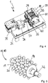
- FIG 4 shows a reduced view of the embodiment of the device 1 according to the invention according to FIG figures 2 and 3 with an open gearbox, in which the crushing roller 11 and the counter-roller 18 are accommodated.
- a main drive motor 35 which drives the crushing roller 11 via a main gear 36 and a clutch 37 serves to drive the rollers 11 and 18 .
- a transmission means 38 which is driven for example in the form of a belt or a chain with a drive element 39 on the roll axis 32 of the crushing roll 11, is used to further drive the counter roll 18 by means of the main drive motor 35.
- a tensioning device 40 is used, over which the transmission means 38 is also guided. The tensioning device can also compensate for short-term changes in the distance between the roller axes 32 and 33.
- FIG 5 shows the crushing roller 11 in a perspective view, wherein the counter-roller 18 can also have such a design.
- the crushing roller 11 has an outer peripheral surface 14 on which a plurality of crushing elements 15 are arranged at regular intervals.
- the crushing roller 11 is accommodated in the roller housing of the device 1 via the roller axis 32 .
- the crushing elements 15 have spherical caps 20 on the head side, which come into contact with the front edge of the surface body 10 and break off fragments from the front edge. In the further circumferential position described above, these breaking elements 15 will again act on the fragments in the intermediate gap to the counter-roller 18 .
- the breaking elements 15 have no cutting edges, and the spherical caps 20 only serve to apply breaking forces to the surface body 10 and the breaking elements broken out of it.
- the exemplary embodiment shows crushing elements 15 screwed into the outer peripheral surface 14 of the crushing roller 11, for which purpose they have a hexagonal section.
- worn breaking elements 15 can also be replaced from the outer peripheral surface 14 in a simple manner.
Landscapes
- Engineering & Computer Science (AREA)
- Food Science & Technology (AREA)
- Environmental & Geological Engineering (AREA)
- Mechanical Engineering (AREA)
- Crushing And Pulverization Processes (AREA)
- Crushing And Grinding (AREA)
Priority Applications (1)
| Application Number | Priority Date | Filing Date | Title |
|---|---|---|---|
| EP20215398.7A EP4015085A1 (fr) | 2020-12-18 | 2020-12-18 | Dispositif de concassage des corps plats en fibre composite |
Applications Claiming Priority (1)
| Application Number | Priority Date | Filing Date | Title |
|---|---|---|---|
| EP20215398.7A EP4015085A1 (fr) | 2020-12-18 | 2020-12-18 | Dispositif de concassage des corps plats en fibre composite |
Publications (1)
| Publication Number | Publication Date |
|---|---|
| EP4015085A1 true EP4015085A1 (fr) | 2022-06-22 |
Family
ID=73855742
Family Applications (1)
| Application Number | Title | Priority Date | Filing Date |
|---|---|---|---|
| EP20215398.7A Pending EP4015085A1 (fr) | 2020-12-18 | 2020-12-18 | Dispositif de concassage des corps plats en fibre composite |
Country Status (1)
| Country | Link |
|---|---|
| EP (1) | EP4015085A1 (fr) |
Cited By (2)
| Publication number | Priority date | Publication date | Assignee | Title |
|---|---|---|---|---|
| CN115430496A (zh) * | 2022-08-24 | 2022-12-06 | 泰州市聚兴物资回收有限公司 | 一种塑料粉碎装置 |
| CN115501934A (zh) * | 2022-09-24 | 2022-12-23 | 东岳机械股份有限公司 | 一种加气混凝土板材破碎机 |
Citations (11)
| Publication number | Priority date | Publication date | Assignee | Title |
|---|---|---|---|---|
| DE8910075U1 (fr) * | 1989-08-23 | 1990-12-20 | Roessler, Peter, 7129 Ilsfeld, De | |
| EP0443051A1 (fr) | 1990-02-17 | 1991-08-28 | FIBRON Gesellschaft mit beschränkter Haftung | Procédé de fabrication d'une matière à mouler thermodurcissable composite en fibres de verre-polyester et dispositif de réalisation du procédé |
| WO1993005883A1 (fr) | 1991-09-18 | 1993-04-01 | Phoenix Fibreglass Inc. | Procede de separation des fibres de materiaux composites |
| EP0547494A1 (fr) | 1991-12-19 | 1993-06-23 | Linde Aktiengesellschaft | Déchiquetage de matériaux en forme de bande |
| US6199778B1 (en) * | 1996-11-06 | 2001-03-13 | Ppg Industries Ohio, Inc. | Systems and processes for recycling glass fiber waste material into glass fiber product |
| JP2003071839A (ja) | 2001-08-30 | 2003-03-12 | Idemitsu Technofine Co Ltd | 複合素材の分離方法、この方法により分離された繊維、樹脂およびこの繊維、樹脂を用いた成形品 |
| WO2006133870A1 (fr) * | 2005-06-16 | 2006-12-21 | Khd Humboldt Wedag Gmbh | Broyeur a cylindres pour broyer du clinker de ciment a haute temperature |
| JP2007054760A (ja) * | 2005-08-25 | 2007-03-08 | Matsushita Electric Works Ltd | 破砕機への成形材料の供給装置 |
| EP1454673B1 (fr) | 2003-03-05 | 2007-07-04 | Rieter CZ a.s. | Dispositif pour broyer des produits en plastique en particulier pour leur recyclage |
| JP2012091134A (ja) | 2010-10-28 | 2012-05-17 | Mitsubishi Materials Corp | 多結晶シリコンの破砕装置及び多結晶シリコン破砕物の製造方法 |
| DE202015104540U1 (de) | 2015-08-27 | 2016-12-15 | Mirko Winter | Querstromzerspaner |
-
2020
- 2020-12-18 EP EP20215398.7A patent/EP4015085A1/fr active Pending
Patent Citations (11)
| Publication number | Priority date | Publication date | Assignee | Title |
|---|---|---|---|---|
| DE8910075U1 (fr) * | 1989-08-23 | 1990-12-20 | Roessler, Peter, 7129 Ilsfeld, De | |
| EP0443051A1 (fr) | 1990-02-17 | 1991-08-28 | FIBRON Gesellschaft mit beschränkter Haftung | Procédé de fabrication d'une matière à mouler thermodurcissable composite en fibres de verre-polyester et dispositif de réalisation du procédé |
| WO1993005883A1 (fr) | 1991-09-18 | 1993-04-01 | Phoenix Fibreglass Inc. | Procede de separation des fibres de materiaux composites |
| EP0547494A1 (fr) | 1991-12-19 | 1993-06-23 | Linde Aktiengesellschaft | Déchiquetage de matériaux en forme de bande |
| US6199778B1 (en) * | 1996-11-06 | 2001-03-13 | Ppg Industries Ohio, Inc. | Systems and processes for recycling glass fiber waste material into glass fiber product |
| JP2003071839A (ja) | 2001-08-30 | 2003-03-12 | Idemitsu Technofine Co Ltd | 複合素材の分離方法、この方法により分離された繊維、樹脂およびこの繊維、樹脂を用いた成形品 |
| EP1454673B1 (fr) | 2003-03-05 | 2007-07-04 | Rieter CZ a.s. | Dispositif pour broyer des produits en plastique en particulier pour leur recyclage |
| WO2006133870A1 (fr) * | 2005-06-16 | 2006-12-21 | Khd Humboldt Wedag Gmbh | Broyeur a cylindres pour broyer du clinker de ciment a haute temperature |
| JP2007054760A (ja) * | 2005-08-25 | 2007-03-08 | Matsushita Electric Works Ltd | 破砕機への成形材料の供給装置 |
| JP2012091134A (ja) | 2010-10-28 | 2012-05-17 | Mitsubishi Materials Corp | 多結晶シリコンの破砕装置及び多結晶シリコン破砕物の製造方法 |
| DE202015104540U1 (de) | 2015-08-27 | 2016-12-15 | Mirko Winter | Querstromzerspaner |
Cited By (2)
| Publication number | Priority date | Publication date | Assignee | Title |
|---|---|---|---|---|
| CN115430496A (zh) * | 2022-08-24 | 2022-12-06 | 泰州市聚兴物资回收有限公司 | 一种塑料粉碎装置 |
| CN115501934A (zh) * | 2022-09-24 | 2022-12-23 | 东岳机械股份有限公司 | 一种加气混凝土板材破碎机 |
Similar Documents
| Publication | Publication Date | Title |
|---|---|---|
| DE3147634C2 (de) | Papierzerkleinerer und Verfahren zum Betrieb | |
| DE102012216914B4 (de) | Zerkleinerungsvorrichtung | |
| EP2338601A2 (fr) | Dispositif de broyage doté d'un dispositif de contre-mesure | |
| EP4015085A1 (fr) | Dispositif de concassage des corps plats en fibre composite | |
| EP2030692B1 (fr) | Broyeur de matière grossière | |
| EP1588786A1 (fr) | Couteau hacheur et contre-couteau pour une machine de hachage et procédé de fabrication d'un tel couteau | |
| EP2714277B1 (fr) | Procédé de fragmentation d'un élastomère et dispositif de fragmentation | |
| EP1237656B1 (fr) | Dispositif de broyage d'un materiau a broyer | |
| DE1632875A1 (de) | Zerkleinerungsmaschine und Verfahren zur Materialzufuhr bei dieser | |
| EP2374544B1 (fr) | Dispositif de broyage de matériaux compostables | |
| DE60105981T2 (de) | Vorrichtung zum zerschneiden von pflanzengut | |
| EP2759345B1 (fr) | Procédé et dispositif de décompactage de matériaux | |
| DE4310689C1 (de) | Verfahren und Vorrichtung zur Aufbereitung mit metallischen Materialien und/oder Gewebefäden bewehrten Gummi- und/oder Kunststoffstücken | |
| DE102018009678A1 (de) | Vorrichtung mit Guillotine-Ablängvorrichtung zum Fertigen eines Verpackungsmaterialerzeugnisses aus einem Faserausgangsmaterial und Verfahren zum Fertigen eines Verpackungsmaterialerzeugnisses | |
| WO2019025297A1 (fr) | Dispositif de broyage doté d'une auto-entrée réglable | |
| EP0567759A2 (fr) | Dispositif pour pulvériser des morceaux de caoutchouc | |
| AT402805B (de) | Häcksler | |
| DE202006000160U1 (de) | Zweiwellen-Shredder für Schaumstoffe | |
| EP0044550A1 (fr) | Procédé et dispositif de débitage d'une plaque en contre-plaqué | |
| DE3704725A1 (de) | Zerkleinerungsmaschine, vorzugsweise fuer altreifen | |
| EP0256241A2 (fr) | Dispositif pour le broyage des matières organiques | |
| DE3009728A1 (de) | Zerkleinerungsanlage, insbesondere zur zerkleinerung von sperrigem abfallmaterial | |
| DE19847532C1 (de) | Verfahren und Vorrichtung zum Auflockern von gepreßtem papierfaserhaltigen Material | |
| DE2344618A1 (de) | Verfahren und vorrichtung zum zerkleinern von wiederaufzuarbeitenden brenn- und/ oder brutelementen fuer kernreaktoren | |
| DE202005000675U1 (de) | Zerkleinerungswerk |
Legal Events
| Date | Code | Title | Description |
|---|---|---|---|
| PUAI | Public reference made under article 153(3) epc to a published international application that has entered the european phase |
Free format text: ORIGINAL CODE: 0009012 |
|
| STAA | Information on the status of an ep patent application or granted ep patent |
Free format text: STATUS: REQUEST FOR EXAMINATION WAS MADE |
|
| 17P | Request for examination filed |
Effective date: 20211228 |
|
| AK | Designated contracting states |
Kind code of ref document: A1 Designated state(s): AL AT BE BG CH CY CZ DE DK EE ES FI FR GB GR HR HU IE IS IT LI LT LU LV MC MK MT NL NO PL PT RO RS SE SI SK SM TR |