EP4013571B1 - Elektrisches, pistolenartiges handgerät - Google Patents
Elektrisches, pistolenartiges handgerät Download PDFInfo
- Publication number
- EP4013571B1 EP4013571B1 EP20734530.7A EP20734530A EP4013571B1 EP 4013571 B1 EP4013571 B1 EP 4013571B1 EP 20734530 A EP20734530 A EP 20734530A EP 4013571 B1 EP4013571 B1 EP 4013571B1
- Authority
- EP
- European Patent Office
- Prior art keywords
- unlocking
- hand
- handheld device
- actuation
- user
- Prior art date
- Legal status (The legal status is an assumption and is not a legal conclusion. Google has not performed a legal analysis and makes no representation as to the accuracy of the status listed.)
- Active
Links
Images

Classifications
-
- F—MECHANICAL ENGINEERING; LIGHTING; HEATING; WEAPONS; BLASTING
- F04—POSITIVE - DISPLACEMENT MACHINES FOR LIQUIDS; PUMPS FOR LIQUIDS OR ELASTIC FLUIDS
- F04D—NON-POSITIVE-DISPLACEMENT PUMPS
- F04D25/00—Pumping installations or systems
- F04D25/02—Units comprising pumps and their driving means
- F04D25/08—Units comprising pumps and their driving means the working fluid being air, e.g. for ventilation
- F04D25/084—Units comprising pumps and their driving means the working fluid being air, e.g. for ventilation hand fans
-
- B—PERFORMING OPERATIONS; TRANSPORTING
- B23—MACHINE TOOLS; METAL-WORKING NOT OTHERWISE PROVIDED FOR
- B23B—TURNING; BORING
- B23B45/00—Hand-held or like portable drilling machines, e.g. drill guns; Equipment therefor
- B23B45/001—Housing of the drill, e.g. handgrip
-
- B—PERFORMING OPERATIONS; TRANSPORTING
- B23—MACHINE TOOLS; METAL-WORKING NOT OTHERWISE PROVIDED FOR
- B23B—TURNING; BORING
- B23B45/00—Hand-held or like portable drilling machines, e.g. drill guns; Equipment therefor
- B23B45/02—Hand-held or like portable drilling machines, e.g. drill guns; Equipment therefor driven by electric power
-
- B—PERFORMING OPERATIONS; TRANSPORTING
- B25—HAND TOOLS; PORTABLE POWER-DRIVEN TOOLS; MANIPULATORS
- B25F—COMBINATION OR MULTI-PURPOSE TOOLS NOT OTHERWISE PROVIDED FOR; DETAILS OR COMPONENTS OF PORTABLE POWER-DRIVEN TOOLS NOT PARTICULARLY RELATED TO THE OPERATIONS PERFORMED AND NOT OTHERWISE PROVIDED FOR
- B25F5/00—Details or components of portable power-driven tools not particularly related to the operations performed and not otherwise provided for
- B25F5/02—Construction of casings, bodies or handles
-
- F—MECHANICAL ENGINEERING; LIGHTING; HEATING; WEAPONS; BLASTING
- F04—POSITIVE - DISPLACEMENT MACHINES FOR LIQUIDS; PUMPS FOR LIQUIDS OR ELASTIC FLUIDS
- F04D—NON-POSITIVE-DISPLACEMENT PUMPS
- F04D27/00—Control, e.g. regulation, of pumps, pumping installations or pumping systems specially adapted for elastic fluids
- F04D27/008—Stop safety or alarm devices, e.g. stop-and-go control; Disposition of check-valves
-
- F—MECHANICAL ENGINEERING; LIGHTING; HEATING; WEAPONS; BLASTING
- F04—POSITIVE - DISPLACEMENT MACHINES FOR LIQUIDS; PUMPS FOR LIQUIDS OR ELASTIC FLUIDS
- F04D—NON-POSITIVE-DISPLACEMENT PUMPS
- F04D29/00—Details, component parts, or accessories
- F04D29/58—Cooling; Heating; Diminishing heat transfer
- F04D29/582—Cooling; Heating; Diminishing heat transfer specially adapted for elastic fluid pumps
-
- F—MECHANICAL ENGINEERING; LIGHTING; HEATING; WEAPONS; BLASTING
- F24—HEATING; RANGES; VENTILATING
- F24H—FLUID HEATERS, e.g. WATER OR AIR HEATERS, HAVING HEAT-GENERATING MEANS, e.g. HEAT PUMPS, IN GENERAL
- F24H3/00—Air heaters
- F24H3/02—Air heaters with forced circulation
- F24H3/04—Air heaters with forced circulation the air being in direct contact with the heating medium, e.g. electric heating element
- F24H3/0405—Air heaters with forced circulation the air being in direct contact with the heating medium, e.g. electric heating element using electric energy supply, e.g. the heating medium being a resistive element; Heating by direct contact, i.e. with resistive elements, electrodes and fins being bonded together without additional element in-between
- F24H3/0423—Air heaters with forced circulation the air being in direct contact with the heating medium, e.g. electric heating element using electric energy supply, e.g. the heating medium being a resistive element; Heating by direct contact, i.e. with resistive elements, electrodes and fins being bonded together without additional element in-between hand-held air guns
-
- H—ELECTRICITY
- H01—ELECTRIC ELEMENTS
- H01H—ELECTRIC SWITCHES; RELAYS; SELECTORS; EMERGENCY PROTECTIVE DEVICES
- H01H13/00—Switches having rectilinearly-movable operating part or parts adapted for pushing or pulling in one direction only, e.g. push-button switch
- H01H13/02—Details
- H01H13/04—Cases; Covers
- H01H13/08—Casing of switch constituted by a handle serving a purpose other than the actuation of the switch
Definitions
- the invention relates to an electric, pistol-like handheld device, in particular a battery-operated, pistol-like handheld device.
- Electric, pistol-like hand tools have a wide range of uses in manual work.
- an electric, pistol-like hand tool can be used as a cordless screwdriver, drill, hammer drill, or even as a drill bit.
- Another use for electric pistol-like hand tools, or especially battery-operated pistol-like hand tools is as a hot air blower, which is also called a hot gun or heat gun.
- Yet another use is the use of the electric, pistol-like hand tool as a hot glue gun. What all of these electric, pistol-like hand tools have in common is that they have a device body for electrically activated processing of a workpiece (mechanically or with hot air) and a handle part that is connected to the device body at an angle like a pistol.
- an electrical accumulator module is usually detachably attached to the underside of the handle to supply the handheld device with electrical energy. Due to the arrangement of the electrical accumulator module on the underside of the handle, the handle usually points vertically with its handle axis downwards when a user grips the handheld device due to the not insignificant weight of the accumulator module. This is also supported by the fact that the electrical handheld device is usually placed on the accumulator module during a work process, so that the handle with its handle axis points along the direction of gravity.
- Such an electric, pistol-like handheld device is usually activated and/or deactivated manually by means of an actuating device, whereby the actuating device is provided, similar to a pistol, as an actuating pushbutton switch in an area of the handle part in which activation by an index finger of a user's hand is possible, as in the case of actuating a weapon trigger.
- the actuating device is provided, similar to a pistol, as an actuating pushbutton switch in an area of the handle part in which activation by an index finger of a user's hand is possible, as in the case of actuating a weapon trigger.
- This intuitive way of operating a pistol-like handheld device is used particularly for handheld devices that require quick activation/deactivation by the user. This is particularly advantageous for a battery-operated hot air blower, where quick activation/deactivation of the hot air blower can reduce power consumption and thus increase battery life.
- hand tools are from the EP0048124A2 , DE102015225723A1 or US2013/205538A1 known.
- the invention is therefore based on the object of providing an electric, pistol-like handheld device, in particular a battery-operated handheld device, which can be unlocked in an ergonomic and simple manner for handheld device operation.
- an electric, pistol-like handheld device which comprises a device body for electrically activated processing of a workpiece, a handle part which is connected to the device body at an angle, an actuating device for manual activation and/or deactivation of the handheld device which is arranged on the device body or the handle part and an unlocking device for manual unlocking and/or locking of the actuating device.
- the unlocking device is arranged on the device body or the handle part in such a way that unlocking takes place by supporting the handheld device in stable equilibrium on one of the fingers of a user's hand when a user grasps the handle part.
- a safety lock is therefore provided which enables the hand-held device to be used without additional effort and without the user making additional movements. At the same time, this prevents the device from being accidentally switched on if it falls over or if it is stored in a delivery van or in a storage room.
- the safety lock is actuated on an axis which is different from the axis of movement of the actuating device or an on/off switch in order to make unintentional actuation of the actuating device or the on/off switch as unlikely as possible.
- the electric, pistol-like hand-held device according to the invention has the advantage that it can be optimally operated and unlocked when working with both the left and right hand.
- the hand-held device further comprises a support pin which projects forward from the finger grip region of the handle part and has the unlocking device on its underside, wherein the unlocking is carried out by supporting the support pin on one of the fingers of the user's hand.
- the support pin can be designed to be concave on its underside to at least partially enclose the unlocking finger against the direction of gravity. This means that during an unlocking process, the pistol-like handset, which is balanced on the unlocking finger in stable equilibrium, not by the unlocking finger.
- the actuating device comprises an electrical actuating push-button switch which is actuated by an activation force against a restoring force transverse to the grip axis of the handle part by one of the fingers of the user's hand.
- the unlocking device comprises an electrical unlocking pushbutton switch which is actuated by a supporting force against gravity along the handle axis of the handle part by one of the fingers of the user's hand.
- the actuating device comprises an actuating touch sensor which is actuated by a touch of the actuating touch sensor in a direction transverse to the handle axis of the handle part by one of the fingers of the user's hand.
- the unlocking device can expediently also comprise an unlocking touch sensor which is actuated by touching the unlocking touch sensor in a direction along the handle axis of the handle part by one of the fingers of the user's hand.
- the unlocking device comprises a mechanical unlocking mechanism which mechanically unlocks the actuating device by means of a supporting force against gravity along the handle axis of the handle part by one of the fingers of the user's hand.
- the mechanical unlocking mechanism can expediently comprise an unlocking rocker which is held in a locking position by a return spring connected to its first end, wherein the second end of the unlocking rocker blocks actuation of the actuating device.
- the second end of the unlocking rocker is U-shaped, whereby when unlocking a button part of the actuating device is guided centrally in the U-shaped end of the release rocker and when locked, the button part hits a locking element at the U-shaped end of the release rocker.
- the actuating device is provided on the handle part or the device body in such a way that it can be actuated by means of an index finger of the user's hand.
- the unlocking device is provided on the handle part or the device body in such a way that the unlocking takes place by means of a middle finger of the user's hand.
- the unlocking device and the actuating device can be provided symmetrically on a handle part or the device body so that unlocking and actuation can be carried out in the same way using a right or left user hand.
- the device is equally easy to operate and easy to unlock for right-handed and left-handed people.
- the handle part can be detachably connected at its lower end facing away from the device body to an electrical accumulator module for supplying the hand-held device with electrical energy.
- the hand-held device is used as a hot gun, wherein the device body has a hot air blower.
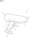
- Fig. 1 shows a schematic and simplified view of an electric, pistol-like and in particular battery-operated hand-held device 10 according to an embodiment of the invention.
- the Fig. 1 The hand-held device 10 shown has a device body 12, by means of which a workpiece can be processed in an electrically activated manner.
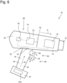
- the invention is not limited to the use of the electric, pistol-like hand-held device as a hot air gun (as with reference to Fig. 6 will be described in more detail below) but can provide a variety of uses.
- the electric, pistol-like hand-held device is a cordless screwdriver, a drill (battery-operated or corded), a hot glue gun, a milling device, a soldering device, a welding device, a stud welding device or generally a hand-held device that requires a locking mechanism or safety mechanism due to dangerous operation when machining a workpiece.
- the device body 12 is preferably provided as an elongated housing, wherein a workpiece processing area 14 can be provided on the front side or distal end of the device body 12. This can be the case in Fig. 6 In the embodiment shown, for example, an air outlet is used as a hot air blower for hot air. However, it is also conceivable that the workpiece processing area 14 is provided, for example, as a drill chuck in which a drilling tool can be accommodated.
- the elongated device body 12 extends along a longitudinal direction A.
- the hand-held device 10 further comprises a handle part 16 which is connected at an angle to the device body 12.
- the handle part 16 extends along a handle axis B such that the longitudinal direction A and the handle axis B are arranged at an angle to one another such that they are at an angle of 70° to 110°, or 80° to 100°, or in particular substantially perpendicular to one another.
- the handle part 16 is thus connected with its first, upper end 18 to a rear, lower region 20 of the device body 12.
- top and bottom refer to a position of the hand-held device 10 in which the handle part 16 is aligned with its handle axis B substantially parallel to the direction of gravity, with the device body 12 being arranged above the handle part 16.
- the longitudinal direction A of the device body 12 runs essentially perpendicular to the direction of gravity and essentially parallel to a horizontal.
- a front region of the hand-held device 10 coincides with the workpiece processing region 14 and a rear region or back region 22 of the device body 12 coincides with a region in which the handle part 16 is provided and which faces a user.
- the unlocking of the hand-held device 10 according to the invention is particularly advantageously supported by the provision of a battery module 24, which can be detachably connected to the handle part 16 at its lower second end facing away from the device body 12 and is provided for supplying the hand-held device 10 with electrical energy.
- the battery module 24 is attached or locked in place in a known manner on the underside of the pistol-shaped handle part 16 of the handle 10.
- the accumulator module 24 has electrical storage means 24a, which are preferably designed as electrical accumulators.
- a lithium-ion battery can be provided as the electrical accumulator 24a, which can be set up for an operating voltage of 18 V.
- the accumulator module 24 By providing the accumulator module 24 as a power supply, operating powers for the handheld device 10 in the range of 600 W to 1200 W can be provided.
- the handle part 16 By providing the accumulator module 24 on the underside of the handle part 16, the handle part 16 extends with its handle axis B perpendicularly, i.e. parallel to the direction of gravity, whereby the unlocking of the handset 10 according to the invention described below is enabled or at least facilitated.
- the electric, pistol-like handheld device 10 has an actuating device 26 for manual activation and/or deactivation of the handheld device 10, which can be arranged on the device body 12 or the handle part 16.
- the actuating device 26 is arranged on the handle part 16, but it is also conceivable that the actuating device 26 is provided on the device body 12.
- the hand-held device 10 has an unlocking device 28, by means of which the actuating device 26 can be manually unlocked and/or locked.
- the unlocking device 28 is arranged according to the invention on the device body 12 or the handle part 16 in such a way that unlocking occurs by supporting the handheld device 12 in stable equilibrium on one of the fingers of a user's hand (not shown) when a user grasps the handle part 16.
- the weight distribution of the handheld device 10 is therefore such that when a user grasps the handle part 16 with a user's hand, one of the fingers of the user's hand, for example the middle finger, slides upwards on the handle part 16 due to the weight of the battery module 24 and in doing so strikes the unlocking device 28, whereby unlocking of the handheld device 10 is triggered when the handheld device 10 is grasped.
- the hand-held device 10 lies balanced in a stable equilibrium with the unlocking device 28 on one of the fingers of the user's hand and is carried or supported in equilibrium by this finger, wherein the unlocking device 28 is actuated by the corresponding supporting force.
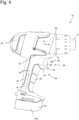
- the hand-held device 10 has a support mandrel 30 which projects forwards from a finger grip area 32 of the handle part 16, i.e. in the direction of the workpiece processing area 14 of the hand-held device 10 and has the unlocking device 28 on its underside, i.e. the side facing the accumulator module 24, wherein the unlocking takes place by supporting the support mandrel 30 on one of the fingers of the user's hand.
- the support pin 30 can be concave on its underside to at least partially enclose the unlocking Fingers against the direction of gravity.
- the finger grip area 32 of the handle part 16 is an area in which the fingers of a user's hand come to rest when using the handset 10. This finger grip area 32 is located on the opposite side of a palm grip area 34 of the handle part 16. As further shown in Fig. 4 As can be seen, the crescent-shaped support pin 30 prevents the hand-held device 10 from slipping off the unlocking finger, on which the handle 10 rests in a stable equilibrium when grasped. Furthermore, the support pin 30 can be provided on the handle part 16 in such a way that the actuating device 26, in particular a push button switch, is arranged between the device body 12 and the support pin 30. This ensures that unintentional actuation is not made more difficult or prevented by the index finger of a user, even when unlocking.
- unlocking device should be understood in general to mean that a locking of the actuating device 26 is removed by any kind of actuation of the unlocking device 28.
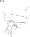
- This unlocking of the actuating device 26 can, for example, be carried out electrically by providing pushbutton switches for the actuating device 26 and the unlocking device 28 (as in Fig. 1 shown), electronically by providing touch sensors (such as in Fig. 2 shown) or mechanically by providing a release mechanism (as for example in Fig. 3 and Fig. 5 shown).
- the unlocking device 28 can thus also be referred to as an unlocking unit, switch-on locking unit, or simply as a locking unit.
- the actuating device 26 comprises an electrical actuating pushbutton switch 36, which is actuated by an activation force against a restoring force transverse to the handle axis B of the handle part 16 by one of the fingers of the user's hand.
- the actuating device 26 is advantageously provided on the handle part 16 or the device body 12 in such a way that the actuation takes place by means of an index finger of the user's hand.
- the electrical actuation switch 36 is more precisely in Fig. 5 shown.
- the actuating pushbutton switch 36 has a button element 38 which is connected to an actuating switching part 42 via a piston element 40 and is guided linearly between an off position and an on position by the piston element 40.
- the piston element 40 is guided into the switching part 42 and triggers a electrical switching process or, depending on a gradual depression depth, a potentiometer process.
- the piston element 40 is moved into an off position against the direction of the button press, for example by a return spring, and is held in this position.
- the unlocking device 28 comprises an electrical unlocking pushbutton switch 44, which is actuated by a supporting force against gravity along the handle axis B of the handle part 16 by one of the fingers of the user's hand.
- the unlocking device 28 is particularly advantageously provided on the handle part 16 or the device body 12 in such a way that the unlocking takes place by means of a middle finger of the user's hand.
- the electrical release button 44 can be designed in a similar way to the electrical actuation button 36.
- the actuating device 26 is unlocked or released, for example, by a series connection of the actuating pushbutton switch 36 and the unlocking pushbutton switch 44, wherein the unlocking pushbutton switch is held in a "normally off” or normally open contact position by a return spring and, when actuated, closes the circuit for operating the handset 10 while the actuating pushbutton switch 36 is simultaneously held down.
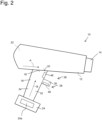
- Fig. 2 shows a further embodiment of a hand-held device 10 according to the invention.
- the actuating device 26 comprises an actuating touch sensor 46, which is actuated by touching the actuating touch sensor 46 in a direction transverse to the handle axis B of the handle part 16 by one of the fingers of the user's hand.
- the hand-held device 10 can also be made of Fig. 2 for the actuating device 26 an actuating push button switch 36, as in Fig. 1 and Fig. 5 shown, will be used.
- the unlocking device 28 comprises an unlocking touch sensor 48, which is actuated by touching the unlocking touch sensor 48 in a direction along the handle axis B of the handle part 16 by one of the fingers of the user's hand.
- the unlocking or unlocking of the actuating device 26 by The unlocking touch sensor 48 can be activated electronically, with an electronic control unit (not shown) capacitively detecting a touch of the unlocking touch sensor 48, for example, and, in the event of a touch event, releasing or closing an electrical circuit which is connected in series with the actuating device 28 for the electrical operation of the handset 10.
- the unlocking device 28 comprises a mechanical unlocking mechanism 50, which mechanically unlocks or releases the actuating device 26 by means of a supporting force against gravity along the handle axis B of the handle part 16 by one of the fingers of the user's hand.
- the mechanical unlocking mechanism 50 can block or lock an actuating pushbutton switch 36 in its actuating direction in different ways.
- the mechanical unlocking mechanism 50 can have a button area 52, which comes into contact with the unlocking finger, and a locking element 54, which releasably makes it difficult or impossible to move the actuating pushbutton switch by means of a frictional or positive locking, or at least blocks it in the actuating direction, so that actuation of the handset 10 is prevented or at least made more difficult.
- FIG. 5 A particularly advantageous embodiment of the mechanical unlocking mechanism 50 is shown in Fig. 5 shown.
- the mechanical unlocking mechanism 50 has an unlocking rocker 56, which is held in a locking position by a return spring 60 connected to its first end 58, wherein the second end 62 of the unlocking rocker 58 enables an actuation of the actuating device 26, in which Fig. 5 shown embodiment of the actuating pushbutton switch 36 is blocked.
- the return spring 60 is designed as a compression spring which engages in a receiving projection 58a of the first end 58 of the release rocker 58 and is supported by a base area of a spring bearing 64 in the handle part 16.
- the pivot bearing 66 of the release rocker 58 is also firmly connected to the handle part 16 so that the release rocker 58 can pivot from a locking position into an unlocking position against the spring force of the return spring 60.
- the second end 62 of the release rocker 58 is U-shaped, whereby during unlocking a rear edge area of the button part 38 of the actuating device 26 is centered in the U-shaped end 62.
- the release rocker 58 is guided, and when locked, the rear edge region of the button part 38, which is designed as an injection-molded hollow part, hits an edge region or the locking element 54 of the U-shaped end 62 of the release rocker 58.
- the U-shaped end 62 of the release rocker 58 is designed such that the button region 52 of the mechanical release mechanism 50 is provided on one leg of the U-shaped end 62 and the locking element 54 of the mechanical release mechanism 50 is provided on the other leg of the U-shaped end 62.
- the locking element 54 is also pivoted upwards, whereby the button element 38 of the actuating pushbutton switch, which is designed as a hollow part, is no longer blocked by the locking element 54 and can move freely in the actuating direction in the central region of the U-shaped end 62.
- both the actuating device 26 and the unlocking device 28 are completely symmetrical or mirror-symmetrical with respect to the plane spanned by the handle axis B and the longitudinal direction A.
- the unlocking device 28 and the actuating device 26 are provided so symmetrically or mirror-symmetrically on the handle part 16 or the device body 12 that unlocking or actuation can be carried out in the same way using a right or left user hand.
- the hand-held device 10 according to the invention can be used and unlocked in the same way by left-handed or right-handed people, and there is no disadvantage if a user changes hands.
- a mechanical lock for the on/off switch is provided.
- the mechanical blocking prevents the on/off switch from being accidentally activated and thus the device from starting.
- the lock engages behind the housing of the on/off switch when it is not activated. If it is activated, the path is cleared and the on/off switch can be pressed. When the on/off switch is pressed, the safety lock no longer needs to be pressed; it is instead held in this position.
- the position of the safety lock is selected so that the natural hand position on the handle already activates the safety lock, but accidental activation is made unlikely. This enables intuitive operation.
- a reliable mechanical blockage of the on/off switch is provided by the release mechanism. 50, as in Fig. 5 shown. This also ensures smooth movement of the unlocking mechanism.
- the unlocking mechanism 50 has few mechanical parts and is easy to assemble. The simple assembly and the few, essentially two mechanical parts reduce assembly and production costs, while the utility value of the handset 10 is increased.
- FIG. 6 A design of the hand-held device 10 as a hot air gun is shown.
- the Fig. 6 The hand-held device 10 shown has an elongated device body 12 with a hot air blower 68, on which an air outlet for heated air is provided as the workpiece processing area 14.
- This heated air is generated by a heating device 70, through which air is sucked in through an air inlet (not shown) by means of a blower device 72 and can exit from the air outlet 14 heated to an operating temperature of up to approximately 700 °C.
- the operating temperature is between 300 °C and 500 °C.
- the blower device 72 has an electric motor 74 and at least one fan wheel 76 that can be driven by the electric motor 74.
- the electric motor 74 of the blower device 72 is designed as a brush motor.
- the control unit 78 is electrically connected to the blower device 72 and the heating device 70.
- the heating device 70 is designed to generate a constant heating output in the range between 300 W and 1,200 W, preferably in the range between 400 W and 600 W or between 800 W and 1,000 W, in particular in the range between 500 W and 600 W or 900 W and 1,000 W.
- the further operation of the hand-held device 10 designed as a hot air blower corresponds to that already described with reference to the Figures 1 to 5 described features, whereby different actuation and release mechanisms, as described above, can be freely combined with each other.
- the Fig. 2 The embodiment shown is not limited to the fact that a touch sensor must be provided for both actuation and unlocking.
Landscapes
- Engineering & Computer Science (AREA)
- Mechanical Engineering (AREA)
- General Engineering & Computer Science (AREA)
- Physics & Mathematics (AREA)
- Thermal Sciences (AREA)
- Chemical & Material Sciences (AREA)
- Combustion & Propulsion (AREA)
- Portable Nailing Machines And Staplers (AREA)
Description
- Die Erfindung betrifft ein elektrisches, pistolenartiges Handgerät, insbesondere ein akkubetriebenes, pistolenartiges Handgerät.
- Elektrische, pistolenartige Handgeräte, insbesondere akkubetriebene pistolenartige Handgeräte finden bei handwerklichen Arbeiten eine Vielzahl von Anwendungen. So findet ein elektrisches, pistolenartiges Handgerät beispielsweise eine Anwendung als Akku-Schrauber, Bohrmaschine, Bohrhammer, oder selbst als Bohrmeißel. Eine weitere Anwendung für elektrische pistolenartige Handgeräte oder insbesondere akkubetriebene pistolenartige Handgeräte ist der Einsatz als Heißluftgebläse, welches auch Heißpistole oder Heatgun genannt wird. Noch eine weitere Anwendung liegt in dem Einsatz des elektrischen, pistolenartigen Handgeräts als Heißklebepistole. Allen diesen genannten elektrischen, pistolenartigen Handgeräten ist gemeinsam, dass sie einen Gerätekörper zur elektrisch aktivierten Bearbeitung eines Werkstücks (mechanisch oder auch mit Heißluft) sowie einen Griffteil aufweisen, der mit dem Gerätekörper pistolenartig gewinkelt verbunden ist.
- Durch die Formgebung eines solchen Handgeräts in Form einer Pistole wird eine ergonomische und kraftschonende Bearbeitung von Werkstücken ermöglicht. Bei einem akkubetriebenen pistolenartigen Handgerät wird in der Regel ein elektrisches Akkumulator-Modul an der Unterseite des Griffteils lösbar befestigt, um das Handgerät mit elektrischer Energie zu versorgen. Durch die Anordnung des elektrischen Akkumulator-Moduls an der Unterseite des Griffteils zeigt aufgrund des nicht zu vernachlässigenden Gewichts des Akkumulator-Moduls der Griffteil bei einem Greifen des Handgeräts durch einen Benutzer in der Regel lotartig mit seiner Griffachse nach unten. Dies wird auch noch dadurch unterstützt, dass bei einem Arbeitsvorgang das elektrische Handgerät in der Regel auf dem Akkumulator-Modul abgestellt wird, so dass der Griffteil mit seiner Griffteilachse entlang der Schwerkraftrichtung zeigt.
- Ein solches elektrisches, pistolenartiges Handgerät wird in der Regel mittels einer Betätigungsvorrichtung manuell aktiviert und/oder deaktiviert, wobei die Betätigungsvorrichtung hierbei, ähnlich wie bei einer Pistole, als Betätigungstastschalter in einem Bereich des Griffteils vorgesehen ist, in welchem eine Aktivierung durch einen Zeigefinger einer Benutzerhand wie bei einer Betätigung eines Waffenabzugs erfolgen kann. Diese intuitive Bedienungsart eines pistolenartigen Handgeräts wird besonders bei Handgeräten eingesetzt, bei welchen eine schnelle Aktivierung / Deaktivierung durch den Benutzer erfolgen soll. Dies ist insbesondere vorteilhaft bei einem akkubetrieben Heißluftgebläse, bei welchem durch eine schnelle Aktivierung / Deaktivierung des Heißluftgebläses der Stromverbrauch reduziert und somit die Akkulaufzeit erhöht werden kann.
- Gerade bei Heißluftpistolen besteht jedoch die Gefahr, dass durch eine unbeabsichtigte Betätigung der Betätigungsvorrichtung das Heißluftgebläse aktiviert wird. Speziell in einem Lieferwagen oder in einer Werkstatt kann es durch ein Umkippen eines solchen Handgeräts oder ein Umfallen in einem Lieferwagen durch eine Aktivierung des Heißluftgebläses zu gefährlichen Situationen kommen, da die Betriebstemperatur von handwerklich eingesetzten Heißluftgebläsen bis zu 700 °C sein kann. Aber auch bei motorisierten Handwerkzeugen kann eine unbeabsichtigte Betätigung einen Schaden an dem Gerät selbst, seiner unmittelbaren Umgebung oder schlimmstenfalls zur Verletzung von Personen führen.
- Daher wird in der Regel bei potenziell gefährlichen pistolenartigen Handgeräten zusammen mit einer Betätigungsvorrichtung eine Entriegelungsvorrichtung vorgesehen, mit welcher die Betätigungsvorrichtung manuell entriegelt und/oder verriegelt werden kann.
- Bisherige Lösungen sehen hier einen mit dem Daumen zu betätigenden Schalter vor, der eingedrückt oder nach unten gedrückt wird, um die Betätigungsvorrichtung wie einen Betätigungstastschalter zu entriegeln. Je nach Handposition und Größe der Benutzerhand sind diese jedoch schwer zu erreichen oder nur durch eine unbequeme Handposition zu betätigen. Oftmals wird durch das während des gesamten Betriebsvorgangs erfolgte Drücken des Daumens auf den Entriegelungsschalter die Handauflagefläche auf der gegenüber liegenden Seite ebenfalls aufgrund eines Vorsehens einer Gegenkraft mit Druck beaufschlagt, was bei längerer Verwendung unbequem ist. Viele der bekannten Mechaniken benötigen mehrere mechanische Teile und bieten somit auch mehr Raum für potentielle Fehler. Hierdurch werden auch höhere Material-, Herstell- und Montagekosten verursacht.
-
DE102012223931A1 offenbart den Oberbegriff des Anspruches 1. - Andere Beispiele von Handwerkzeugen sind aus der
EP0048124A2 ,DE102015225723A1 oderUS2013/205538A1 bekannt. - Der Erfindung liegt demnach die Aufgabe zugrunde, ein elektrisches, pistolenartiges Handgerät, insbesondere ein akkubetriebenes Handgerät vorzusehen, welches in ergonomischer und einfacher Weise für einen Handgerätebetrieb entriegelt werden kann.
- Diese Aufgabe wird durch das elektrische, pistolenartige Handgerät nach Anspruch 1 gelöst. Vorteilhafte Ausgestaltungen und Weiterbildungen der Erfindung sind in den Unteransprüchen angegeben.
- Erfindungsgemäß ist ein elektrisches, pistolenartiges Handgerät vorgesehen, welches einen Gerätekörper zur elektrisch aktivierten Bearbeitung eines Werkstücks, einen Griffteil, der mit dem Gerätekörper gewinkelt verbunden ist, eine Betätigungsvorrichtung zur manuellen Aktivierung und/oder Deaktivierung des Handgeräts, die an dem Gerätekörper oder dem Griffteil angeordnet ist und eine Entriegelungsvorrichtung zur manuellen Entriegelung und/oder Verriegelung der Betätigungsvorrichtung umfasst. Hierbei ist die Entriegelungsvorrichtung so an dem Gerätekörper oder dem Griffteil angeordnet, dass eine Entriegelung durch ein Abstützen des Handgeräts im stabilen Gleichgewicht auf einem der Finger einer Benutzerhand beim Greifen des Griffteils durch einen Benutzer erfolgt.
- Erfindungsgemäß wird also eine Sicherheitsverriegelung vorgesehen, die ohne Mehraufwand und ohne dass ein Verwender zusätzliche Bewegungen macht, die Verwendung des Handgerätes ermöglicht. Dabei wird gleichzeitig ein versehentliches Einschalten des Gerätes bei einem Umfallen oder in einer möglichen Aufbewahrung in einem Lieferwagen oder in einem Lagerraum verhindert. Die Sicherheitsverriegelung wird dabei in einer Achse betätigt, die sich von der Bewegungsachse der Betätigungsvorrichtung oder eines Ein-/Ausschalters unterscheidet, um eine unbeabsichtigte Betätigung der Betätigungsvorrichtung oder des Ein-/Ausschalters so unwahrscheinlich wie möglich zu machen. Darüber hinaus weist das erfindungsgemäß elektrische, pistolenartige Handgerät den Vorteil auf, dass es sich sowohl bei Arbeiten mit der linken als auch mit der rechten Hand optimal bedienen und entriegeln lässt.
- Wie in Anspruch 1 dargestellt, weist das Handgerät ferner einen Abstützdorn auf, der von dem Fingergriffbereich des Griffteils nach vorne ragt und an seiner Unterseite die Entriegelungsvorrichtung aufweist, wobei die Entriegelung durch ein Abstützen des Abstützdorns auf einem der Finger der Benutzerhand erfolgt.
- Um ein Abrutschen des Handgerätes von dem entriegelnden Finger zu erschweren oder zu verhindern, kann der Abstützdorn an seiner Unterseite konkav zur zumindest teilweise umschließenden Aufnahme des entriegelnden Fingers entgegen der Schwerkraftrichtung ausgebildet sein. Somit rutscht also bei einem Entriegelungsvorgang das pistolenartige Handgerät, das auf dem entriegelnden Finger im stabilen Gleichgewicht ausbalanciert ist, nicht von dem entriegelnden Finger.
- Um eine einfache Bauweise der Betätigungsvorrichtung des Handgeräts zu erreichen, ist es von Vorteil, wenn die Betätigungsvorrichtung einen elektrischen Betätigungstastschalter umfasst, der durch eine Aktivierungskraft gegen eine Rückstellkraft quer zur Griffachse des Griffteils durch einen der Finger der Benutzerhand betätigt wird.
- Um in ähnlicher Weise eine wie bei der Betätigungsvorrichtung einfache Bauweise der Entriegelungsvorrichtung vorzusehen, ist es zweckmäßig, wenn die Entriegelungsvorrichtung einen elektrischen Entriegelungstastschalter umfasst, der durch eine Abstützkraft gegen die Schwerkraft entlang der Griffachse des Griffteils durch einen der Finger der Benutzerhand betätigt wird.
- Gemäß einer Weiterbildung der Erfindung ist es jedoch auch von Vorteil, wenn die Betätigungsvorrichtung einen Betätigungs-Berührungssensor umfasst, der durch eine Berührung des Betätigungs-Berührungssensors in einer Richtung quer zur Griffachse des Griffteils durch einen der Finger der Benutzerhand betätigt wird.
- Hierbei kann zweckmäßigerweise auch die Entriegelungsvorrichtung einen Entriegelungs-Berührungssensor umfassen, der durch eine Berührung des Entriegelungs-Berührungssensors in einer Richtung entlang der Griffachse des Griffteils durch einen der Finger der Benutzerhand betätigt wird.
- Für eine besonders einfache, kompakte und stabile Bauweise des erfindungsgemäßen Handgeräts ist es zweckmäßig, wenn die Entriegelungsvorrichtung einen mechanischen Entriegelungsmechanismus umfasst, der durch eine Abstützkraft gegen die Schwerkraft entlang der Griffachse des Griffteils durch einen der Finger der Benutzerhand die Betätigungsvorrichtung mechanisch entriegelt.
- Hierbei kann der mechanische Entriegelungsmechanismus in zweckmäßiger Weise eine Entriegelungswippe aufweisen, welche durch eine an ihrem ersten Ende verbundene Rückstellfeder in einer Verriegelungsstellung gehalten wird, wobei das zweite Ende der Entriegelungswippe eine Betätigung der Betätigungsvorrichtung blockiert.
- Dabei ist es von Vorteil, wenn das zweite Ende der Entriegelungswippe U-förmig ausgebildet ist, wobei bei einer Entriegelung ein Tastenteil der Betätigungsvorrichtung mittig im U-förmigen Ende der Entriegelungswippe geführt wird und bei einer Verriegelung das Tastenteil auf ein Sperrelement am U-förmigen Ende der Entriegelungswippe stößt.
- Um eine möglichst intuitive Bedienung des elektrischen, pistolenartigen Handgeräts zu ermöglichen, ist es von Vorteil, wenn die Betätigungsvorrichtung so an dem Griffteil oder dem Gerätekörper vorgesehen ist, dass die Betätigung mittels eines Zeigefingers der Benutzerhand erfolgt.
- Für eine besonders einfache Umsetzung der Erfindung, insbesondere bei einem Vorsehen eines Abstützdorns am vorderen Teil des Griffteils ist es von Vorteil, wenn die Entriegelungsvorrichtung so an dem Griffteil oder dem Gerätekörper vorgesehen ist, dass die Entriegelung mittels eines Mittelfingers der Benutzerhand erfolgt.
- Erfindungsgemäß kann die Entriegelungsvorrichtung und die Betätigungsvorrichtung so symmetrisch an einem Griffteil oder dem Gerätekörper vorgesehen sein, dass eine Entriegelung und eine Betätigung in gleicher Weise mittels einer rechten oder linken Benutzerhand durchführbar sind. Somit lässt sich erfindungsgemäß sowohl mit der linken als auch mit der rechten Hand optimal arbeiten, ohne dass ein Nachteil bei einem Handwechsel entsteht. Darüber hinaus ist das Gerät in gleicher Weise für Rechtshänder und Linkshänder einfach zu bedienen und einfach zu entriegeln.
- In einer besonders vorteilhaften Ausgestaltung als akkubetriebenes Handgerät ist es zweckmäßig, wenn der Griffteil an seinem dem Gerätekörper abgewandten, unteren Ende lösbar mit einem elektrischen Akkumulator-Modul zur Versorgung des Handgeräts mit elektrischer Energie verbindbar ist.
- Insbesondere ist es erfindungsgemäß vorgesehen, dass das Handgerät als Heißpistole eingesetzt wird, wobei der Gerätekörper ein Heißluftgebläse aufweist.
- Die Erfindung wird im Folgenden beispielsweise anhand der Zeichnungen näher erläutert. Es zeigen:
-
Fig. 1 eine schematische Ansicht eines elektrischen, pistolenartigen Handgeräts gemäß einem Ausführungsbeispiel der Erfindung, -
Fig. 2 eine schematische Ansicht eines Handgeräts gemäß einem weiteren Ausführungsbeispiel der Erfindung, -
Fig. 3 eine schematische Ansicht eines Handgeräts gemäß noch einem weiteren Ausführungsbeispiel der Erfindung, -
Fig. 4 eine schematische perspektivische Ansicht eines Handgeräts gemäß einem Ausführungsbeispiel der Erfindung, -
Fig. 5 eine schematische Ansicht eines mechanischen Entriegelungsmechanismus und einer Betätigungsvorrichtung gemäß einem Ausführungsbeispiel der Erfindung, und -
Fig. 6 eine schematische Ansicht eines als Heißluftpistole ausgebildeten Handgeräts gemäß einem Ausführungsbeispiel der Erfindung. - In den verschiedenen Figuren der Zeichnungen sind einander entsprechende Bauelemente mit gleichen Bezugszeichen versehen.
-
Fig. 1 zeigt eine schematische und vereinfachte Ansicht eines elektrischen, pistolenartigen und insbesondere akkubetrieben Handgeräts 10 gemäß einem Ausführungsbeispiel der Erfindung. - Das in
Fig. 1 dargestellte Handgerät 10 weist einen Gerätekörper 12 auf, mittels dessen ein Werkstück elektrisch aktiviert bearbeitet werden kann. Hierbei ist die Erfindung nicht auf den Einsatz des elektrischen, pistolenartigen Handgeräts als Heißluftpistole (wie mit Bezug aufFig. 6 noch genauer beschrieben werden wird) eingeschränkt, sondern kann eine Vielzahl von Verwendungen bereitstellen. So ist es beispielsweise möglich, dass das erfindungsgemäße elektrische, pistolenartige Handgerät ein Akku-Schrauber, eine Bohrmaschine (akkubetrieben oder kabelgebunden), eine Heißklebepistole, eine Fräs-Vorrichtung, eine Löt-Vorrichtung, eine Schweiß-Vorrichtung, ein Bolzen-Schweißgerät oder generell ein Handgerät ist, das aufgrund eines gefahrvollen Betriebs bei einer Bearbeitung eines Werkstücks einen Verriegelungsmechanismus oder Sicherungsmechanismus benötigt. - Der Gerätekörper 12 ist vorzugsweise als langgestreckt ausgebildetes Gehäuse vorgesehen, wobei an dessen Vorderseite oder distalen Ende des Gerätekörpers 12 ein Werkstückbearbeitungsbereich 14 vorgesehen sein kann. Dies kann bei dem in
Fig. 6 gezeigten Ausführungsbeispiel als Heißluftgebläse beispielsweise ein Luftauslass für Heißluft sein. Es ist jedoch auch vorstellbar, dass der Werkstückbearbeitungsbereich 14 beispielsweise als Bohrfutter vorgesehen ist, in welchem ein Bohrwerkzeug aufgenommen werden kann. Der langgestreckt ausgebildete Gerätekörper 12 erstreckt sich entlang einer Längsrichtung A. - Das Handgerät 10 weist ferner einen Griffteil 16 auf, welcher mit dem Gerätekörper 12 gewinkelt verbunden ist. Der Griffteil 16 erstreckt sich entlang einer Griffachse B, so dass die Längsrichtung A und die Griffachse B zueinander so gewinkelt angeordnet sind, dass sie in einem Winkel von 70 ° bis 110 °, oder 80 ° bis 100 °, oder insbesondere im Wesentlichen senkrecht zueinander stehen. Der Griffteil 16 ist also mit seinem ersten, oberen Ende 18 mit einem rückseitigen unteren Bereich 20 des Gerätekörpers 12 verbunden. Auch wenn das pistolenartige Handgerät 10 bei einem Bearbeitungsvorgang in unterschiedlichen Lagen zur Schwerkraftrichtung gehalten werden kann, beziehen sich die Begriffe oben und unten auf eine Lage des Handgeräts 10, in welchem der Griffteil 16 mit seiner Griffachse B im Wesentlichen parallel zur Schwerkraftrichtung ausgerichtet ist, wobei der Gerätekörper 12 über dem Griffteil 16 angeordnet ist. Hierbei verläuft die Längsrichtung A des Gerätekörpers 12 im Wesentlichen senkrecht zur Schwerkraftrichtung und im Wesentlichen parallel zu einer Horizontalen. Des Weiteren fällt ein vorderer Bereich des Handgeräts 10 mit dem Werkstückbearbeitungsbereich 14 und ein hinterer Bereich oder rückseitiger Bereich 22 des Gerätekörpers 12 mit einem Bereich zusammen, in welchem der Griffteil 16 vorgesehen ist und welcher einem Benutzer zugewandt ist.
- Die erfindungsgemäße Entriegelung des Handgeräts 10 wird in besonders vorteilhafter Weise durch das Vorsehen eines Akkumulator-Moduls 24 unterstützt, das mit dem Griffteil 16 an dessen dem Gerätekörper 12 abgewandten, unteren zweiten Ende lösbar verbindbar ist und zur Versorgung des Handgeräts 10 mit elektrische Energie vorgesehen ist. Das Akkumulator-Modul 24 ist in bekannter Weise an der Unterseite des pistolenförmigen Griffteils 16 des Handgriffs 10 angebracht, bzw. eingerastet.
- Das Akkumulator-Modul 24 weist elektrische Speichermittel 24a auf, welche vorzugsweise als elektrische Akkumulatoren ausgebildet sind. Als elektrischer Ackumulator 24a kann hierbei ein Lithium-Ionen-Akku vorgesehen werden, welcher auf eine Betriebsspannung von 18 V eingerichtet sein kann. Durch das Vorsehen des Akkumulator-Moduls 24 als Stromversorgung können Betriebsleistungen für das Handgerät 10 im Bereich von 600 W bis 1200 W vorgesehen werden. Durch das Vorsehen des Akkumulator-Moduls 24 an der Unterseite des Griffteils 16 richtet sich der Griffteil 16 mit seiner Griffachse B lotartig, also parallel zur Schwerkraftrichtung, aus, wodurch die im Folgenden beschriebene erfindungsgemäße Entriegelung des Handgeräts 10 ermöglicht oder zumindest erleichtert wird.
- So weist das elektrische, pistolenartige Handgerät 10 zur manuellen Aktivierung und/oder Deaktivierung des Handgeräts 10 eine Betätigungsvorrichtung 26 auf, die an dem Gerätekörper 12 oder dem Griffteil 16 angeordnet sein kann. In dem in
Fig. 1 gezeigten Ausführungsbeispiel ist die Betätigungsvorrichtung 26 an dem Griffteil 16 angeordnet, es ist jedoch auch vorstellbar, dass die Betätigungsvorrichtung 26 am Gerätekörper 12 vorgesehen ist. - Des Weiteren weist das Handgerät 10 erfindungsgemäß eine Entriegelungsvorrichtung 28 auf, mittels derer die Betätigungsvorrichtung 26 manuell entriegelt und/oder verriegelt werden kann. Wie beispielsweise in
Fig. 1 gezeigt, ist die Entriegelungsvorrichtung 28 erfindungsgemäß so an dem Gerätekörper 12 oder dem Griffteil 16 angeordnet, dass eine Entriegelung durch ein Abstützen des Handgeräts 12 im stabilen Gleichgewicht auf einem der Finger einer Benutzerhand (nicht gezeigt) beim Greifen des Griffteils 16 durch einen Benutzer erfolgt. Erfindungsgemäß ist also die Gewichtsverteilung des Handgeräts 10 so beschaffen, dass durch das Gewicht des Akkumulator-Moduls 24 bei einem Greifen des Griffteils 16 durch einen Benutzer mittels einer Benutzerhand einer der Finger der Benutzerhand, beispielsweise der Mittelfinger am Griffteil 16 nach oben rutscht und dabei gegen die Entriegelungsvorrichtung 28 stößt, wodurch bei einem Ergreifen des Handgeräts 10 eine Entriegelung des Handgeräts 10 ausgelöst wird. In besonders vorteilhafter Weise liegt dabei das Handgerät 10 ausbalanciert in einem stabilen Gleichgewicht mit der Entriegelungsvorrichtung 28 auf einem der Finger der Benutzerhand und wird durch diesen Finger im Gleichgewicht getragen oder abgestützt, wobei durch die entsprechende Stützkraft die Entriegelungsvorrichtung 28 betätigt wird. - Gemäß einem weiteren vorteilhaften Ausführungsbeispiel der Erfindung weist das Handgerät 10 einen Abstützdorn 30 auf, der von einem Fingergriffbereich 32 des Griffteils 16 nach vorne, also in Richtung des Werkstückbearbeitungsbereichs 14 des Handgeräts 10 ragt und an seiner Unterseite, also der dem Akkumulator-Modul 24 zugewandten Seite, die Entriegelungsvorrichtung 28 aufweist, wobei die Entriegelung durch ein Abstützen des Abstützdorns 30 auf einem der Finger der Benutzerhand erfolgt. Wie beispielsweise in der perspektivischen Ansicht des Griffteils 16 in
Fig. 4 ersichtlich, kann dabei der Abstützdorn 30 an seiner Unterseite konkav zur zumindest teilweise umschließenden Aufnahme des entriegelnden Fingers entgegen der Schwerkraftrichtung ausgebildet sein. Der Fingergriffbereich 32 des Griffteils 16 ist ein Bereich, in welchem bei einer Benutzung des Handgeräts 10 die Finger einer Benutzerhand zum Liegen kommen. Dieser Fingergriffbereich 32 liegt dabei auf der gegenüberliegenden Seite eines Handballengriffbereichs 34 des Griffteils 16. Wie weiter ausFig. 4 ersichtlich ist, wird durch den halbmond-förmigen Abstützdorn 30 ein Abrutschen des Handgeräts 10 von dem entriegelnden Finger, auf welchem bei einem Greifen der Handgriff 10, in stabilem Gleichgewicht ausbalanciert, zum Liegen kommt. Ferner kann der Abstützdorn 30 so am Griffteil 16 vorgesehen sein, dass die Betätigungsvorrichtung 26, insbesondere ein Tastschalter, zwischen dem Gerätekörper 12 und dem Abstützdorn 30 angeordnet ist. Somit wird sichergestellt, dass eine unbeabsichtigte Betätigung nicht durch den Zeigefinger eines Benutzers selbst bei einer Entriegelung erschwert oder verhindert wird. - Der technische Begriff Entriegelungsvorrichtung soll ganz allgemein dahingehend verstanden werden, dass durch eine wie auch immer geartete Betätigung der Entriegelungsvorrichtung 28 eine Sperrung der Betätigungsvorrichtung 26 aufgehoben wird. Diese Entsperrung der Betätigungsvorrichtung 26 kann beispielsweise elektrisch durch das Vorsehen von Tastschaltern für die Betätigungsvorrichtung 26 und die Entriegelungsvorrichtung 28 (wie in
Fig. 1 gezeigt), elektronisch durch das Vorsehen von Berührungs-Sensoren (wie beispielsweise inFig. 2 gezeigt) oder auch mechanisch durch das Vorsehen eines Entriegelungsmechanismus (wie beispielsweise inFig. 3 undFig. 5 gezeigt) erfolgen. Die Entriegelungsvorrichtung 28 kann somit auch als Entsperreinheit, Einschaltsperreinheit, oder einfach als Sperreinheit bezeichnet werden. - Gemäß dem Ausführungsbeispiel in
Fig. 1 umfasst die Betätigungsvorrichtung 26 einen elektrischen Betätigungstastschalter 36, der durch eine Aktivierungskraft gegen eine Rückstellkraft quer zur Griffachse B des Griffteils 16 durch einen der Finger der Benutzerhand betätigt wird. Dabei ist die Betätigungsvorrichtung 26 vorteilhafterweise so an dem Griffteil 16 oder dem Gerätekörper 12 vorgesehen, dass die Betätigung mittels eines Zeigefingers der Benutzerhand erfolgt. - Der elektrische Betätigungstastschalter 36 ist genauer in
Fig. 5 gezeigt. So weist der Betätigungstastschalter 36 ein Tastenelement 38 auf, welches über ein Kolbenelement 40 mit einem Betätigungsschaltteil 42 verbunden ist und durch das Kolbenelement 40 linear zwischen einer Aus-Stellung und einer An-Stellung linear geführt wird. Mit anderen Worten wird durch das Drücken des Tastenelements 38 das Kolbenelement 40 in das Schaltteil 42 hineingeführt und löst dort einen elektrischen Schaltvorgang oder abhängig von einer graduellen Eindrücktiefe einen Potentiometer-Vorgang aus. Das Kolbenelement 40 wird dabei entgegen der Tastendruck-Richtung beispielsweise durch eine Rückstellfeder in eine Aus-Stellung bewegt und in dieser gehalten. - In dem in
Fig. 1 gezeigten Ausführungsbeispiel umfasst die Entriegelungsvorrichtung 28 einen elektrischen Entriegelungstastschalter 44, der durch eine Abstützkraft gegen die Schwerkraft entlang der Griffachse B des Griffteils 16 durch einen der Finger der Benutzerhand betätigt wird. Hierbei ist in besonders vorteilhafter Weise die Entriegelungsvorrichtung 28 so an dem Griffteil 16 oder dem Gerätekörper 12 vorgesehen, dass die Entriegelung mittels eines Mittelfingers der Benutzerhand erfolgt. - Der elektrische Entriegelungstastschalter 44 kann dabei in ähnlicher Weise wie der elektrische Betätigungstastschalter 36 ausgebildet sein. Bei diesem Ausführungsbeispiel gemäß
Fig. 1 erfolgt eine Entriegelung oder Entsperrung der Betätigungsvorrichtung 26 beispielsweise durch eine Serienschaltung des Betätigungstastschalters 36 und des Entriegelungstastschalters 44, wobei der Entriegelungstastschalter durch eine Rückstellfeder in einer "Normally-Off" oder Arbeitskontakt-Stellung gehalten wird und bei einem Betätigen den Stromkreis zum Betrieb des Handgeräts 10 bei einem gleichzeitigen Gedrückt-halten des Betätigungstastschalters 36 schließt. -
Fig. 2 zeigt ein weiteres Ausführungsbeispiel eines erfindungsgemäßen Handgeräts 10. Hier umfasst die Betätigungsvorrichtung 26 einen Betätigungs-Berührungssensor 46, der durch eine Berührung des Betätigungs-Berührungssensors 46 in einer Richtung quer zur Griffachse B des Griffteils 16 durch einen der Finger der Benutzerhand betätigt wird. Statt einem Betätigungs-Berührungssensor 46 kann jedoch auch bei dem Handgerät 10 ausFig. 2 für die Betätigungsvorrichtung 26 ein Betätigungstastschalter 36, wie inFig. 1 undFig. 5 gezeigt, zum Einsatz kommen. - In
Fig. 2 erfolgt die Betätigung wiederum durch einen Zeigefinger und die Entriegelung durch einen Mittelfinger. Die Erfindung soll jedoch nicht auf diese Ausgestaltung beschränkt sein, ist jedoch besonders vorteilhaft. Die Entriegelungsvorrichtung 28 umfasst einen Entriegelungs-Berührungssensor 48, der durch eine Berührung des Entriegelungs-Berührungssensors 48 in einer Richtung entlang der Griffachse B des Griffteils 16 durch einen der Finger der Benutzerhand betätigt wird. Die Entriegelung oder Entsperrung der Betätigungsvorrichtung 26 durch den Entriegelungs-Berührungssensor 48 kann dabei elektronisch erfolgen, wobei eine elektronische Steuereinheit (nicht gezeigt) eine Berührung des Entriegelungs-Berührungssensors 48 beispielsweise kapazitiv erfasst und bei einem Berührungsereignis einen Stromkreis, welcher in Serie mit der Betätigungsvorrichtung 28 geschaltet ist, zum elektrischen Betrieb des Handgeräts 10 freigibt oder schließt. - In
Fig. 3 ist schließlich ein mechanischer Entriegelungsvorgang vorgesehen. Hierbei umfasst die Entriegelungsvorrichtung 28 einen mechanischen Entriegelungsmechanismus 50, der durch eine Abstützkraft gegen die Schwerkraft entlang der Griffachse B des Griffteils 16 durch einen der Finger der Benutzerhand die Betätigungsvorrichtung 26 mechanisch entriegelt oder entsperrt. - Der mechanische Entriegelungsmechanismus 50 kann auf unterschiedliche Weisen einen Betätigungstastschalter 36 in seiner Betätigungsrichtung blockieren oder sperren. Hierfür kann der mechanische Entriegelungsmechanismus 50 einen Tastenbereich 52, welcher in Kontakt mit dem entriegelnden Finger tritt, und ein Sperrelement 54 aufweisen, welches durch einen Reibschluss oder Formschluss lösbar eine Bewegung des Betätigungstastschalters erschwert oder verhindert oder zumindest in Betätigungsrichtung blockiert, so dass eine Betätigung des Handgeräts 10 verhindert oder zumindest erschwert wird.
- Eine besonders vorteilhafte Ausgestaltung des mechanischen Entriegelungsmechanismus 50 ist in
Fig. 5 gezeigt. Hierbei weist der mechanische Entriegelungsmechanismus 50 eine Entriegelungswippe 56 auf, welche durch eine an ihrem ersten Ende 58 verbundene Rückstellfeder 60 in einer Verriegelungsstellung gehalten wird, wobei das zweite Ende 62 der Entriegelungswippe 58 eine Betätigung der Betätigungsvorrichtung 26, in dem inFig. 5 gezeigten Ausführungsbeispiel des Betätigungstastschalters 36 blockiert. - Dabei ist die Rückstellfeder 60 als Druckfeder ausgebildet, welche in einem Aufnahmevorsprung 58a des ersten Endes 58 der Entriegelungswippe 58 eingreift und sich von einem Bodenbereich eines Federlagers 64 in dem Griffteil 16 abstützt. Das Drehlager 66 der Entriegelungswippe 58 ist ebenfalls fest mit dem Griffteil 16 so verbunden, dass die Entriegelungswippe 58 entgegen der Federkraft der Rückstellfeder 60 aus einer Verriegelungsstellung in eine Entriegelungsstellung schwenken kann. Hierfür ist das zweite Ende 62 der Entriegelungswippe 58 U-förmig ausgebildet, wobei bei einer Entriegelung ein rückseitiger Randbereich des Tastenteils 38 der Betätigungsvorrichtung 26 mittig im U-förmigen Ende 62 der Entriegelungswippe 58 geführt wird, und bei einer Verriegelung der rückseitige Randbereich des Tastenteils 38, welches als Spritzgusshohlteil ausgebildet ist, auf einen Randbereich oder das Sperrelement 54 des U-förmigen Endes 62 der Entriegelungswippe 58 stößt. Das U-förmige Ende 62 der Entriegelungswippe 58 ist dabei so ausgebildet, dass an dem einen Schenkel des U-förmigen Endes 62 der Tastenbereich 52 des mechanischen Entriegelungsmechanismus 50 und an dem anderen Schenkel des U-förmigen Endes 62 das Sperrelement 54 des mechanischen Entriegelungsmechanismus 50 vorgesehen ist. Bei einem Schwenken der Entriegelungswippe 58 aufgrund der Entriegelungskraft durch einen der Finger der Benutzerhand nach oben wird dabei das Sperrelement 54 ebenfalls nach oben geschwenkt, wodurch das als Hohlteil ausgebildete Tastenelement 38 des Betätigungstastschalter nicht mehr durch das Sperrelement 54 blockiert wird und sich in dem Mittelbereich des U-förmigen Endes 62 frei in Betätigungsrichtung bewegen kann.
- Wie aus den gesamten
Figuren 1 bis 6 hervorgeht, ist sowohl die Betätigungsvorrichtung 26 als auch die Entriegelungsvorrichtung 28 vollkommen symmetrisch oder auch spiegelsymmetrisch bezüglich der durch die Griffachse B und der Längsrichtung A aufgespannten Ebene. Somit sind erfindungsgemäß die Entriegelungsvorrichtung 28 und die Betätigungsvorrichtung 26 so symmetrisch oder spiegelsymmetrisch an dem Griffteil 16 oder dem Gerätekörper 12 vorgesehen, dass eine Entriegelung oder eine Betätigung in gleicher Weise mittels einer rechten oder linken Benutzerhand durchführbar sind. Somit lässt sich das erfindungsgemäße Handgerät 10 in gleicher Weise durch Linkshänder oder Rechtshänder benutzen und entsperren, wobei auch kein Nachteil entsteht bei einem Handwechsel durch einen Benutzer. - Wie in
Fig. 5 also gezeigt, wird eine mechanische Verriegelung des Ein-/Ausschalters vorgesehen. Durch die mechanische Blockierung wird ein unbeabsichtigtes Betätigen des Ein-/Ausschalters und damit ein Start des Gerätes verhindert. Die Verriegelung greift hinter das Gehäuse des Ein-/Ausschalters, wenn sie nicht betätigt wird. Wird sie betätigt, ist der Weg freigegeben und der Ein-/Ausschalter kann gedrückt werden. Wenn der Ein-/Ausschalter gedrückt ist, muss die Sicherheitsverriegelung nicht mehr gedrückt werden, sie wird vielmehr in dieser Position gehalten. Die Position der Sicherheitsverriegelung ist so gewählt, dass durch die natürliche Handhaltung am Handgriff die Sicherheitsverriegelung bereits betätigt wird, aber ein versehentliches Betätigen unwahrscheinlich gemacht wird. Somit wird eine intuitive Bedienung ermöglicht. Weiter ist eine zuverlässige mechanische Blockade des Ein-/Ausschalters durch den Entriegelungsmechanismus 50, wie inFig. 5 gezeigt, vorgesehen. Dieser stellt darüber hinaus eine leichtgängige Bewegung des Entriegelungsmechanismus sicher. Zudem weist der Entriegelungsmechanismus 50 wenig mechanische Teile auf und ist leicht zu montieren. Durch die einfache Montage und die wenigen, im Wesentlichen zwei mechanischen Teile werden die Montage und Herstellung kostenreduziert, während der Nutzwert des Handgerätes 10 erhöht wird. - In
Fig. 6 ist eine Ausgestaltung des Handgeräts 10 als Heißluftpistole dargestellt. Hierfür weist das inFig. 6 dargestellte Handgerät 10 einen langgestreckt ausgebildeten Gerätekörper 12 mit einem Heißluftgebläse 68 auf, an welchem als Werkstückbearbeitungsbereich 14 ein Luftauslass für erwärmte Luft vorgesehen ist. - Diese erwärmte Luft wird erzeugt durch eine Heizeinrichtung 70, durch welche mittels einer Gebläse-Einrichtung 72 durch einen Lufteinlass (nicht gezeigt) angesaugte Luft gebracht wird und aus dem Luftauslass 14 auf eine Betriebstemperatur von bis zu ca. 700 °C erwärmt, austreten kann. Die Betriebstemperatur liegt hierbei bei 300 °C und 500 °C.
- Die Gebläse-Einrichtung 72 weist zur Erzeugung des Luftstroms einen Elektromotor 74 und zumindest ein mittels des Elektromotors 74 antreibbares Lüfterrad 76 auf. Der Elektromotor 74 der Gebläse-Einrichtung 72 ist als Bürstenmotor ausgebildet. Eine schematische gezeigte Steuereinheit 78 bewirkt sowohl eine Temperaturregelung als auch eine geeignete Ansteuerung der Heizeinrichtung 70 bzw. Gebläse-Einrichtung 72. Die Steuereinheit 78 ist elektrisch mit der Gebläse-Einrichtung 72 und der Heizeinrichtung 70 verbunden. Die Heizeinrichtung 70 ist dazu ausgebildet, eine konstante Heizleistung im Bereich zwischen 300 W und 1.200 W, vorzugsweise im Bereich zwischen 400 W und 600 W bzw. zwischen 800 W und 1.000 W, insbesondere in Bereichen zwischen 500 W und 600 W bzw. 900 W und 1.000 W zu erzeugen.
- Der weitere Betrieb des als Heißluftgebläses ausgestalteten Handgeräts 10 entspricht dem bereits mit Bezug auf die
Figuren 1 bis 5 beschriebenen Merkmalen, wobei unterschiedliche Betätigungs- und Entriegelungsmechanismen, wie oben beschrieben, frei miteinander kombiniert werden können. So ist beispielsweise das inFig. 2 gezeigte Ausführungsbeispiel nicht darauf beschränkt, dass sowohl für die Betätigung als auch für die Entriegelung ein Berührungs-Sensor vorgesehen sein muss.
Claims (14)
- Elektrisches, pistolenartiges Handgerät (10), mit- einem Gerätekörper (12) zur elektrisch aktivierten Bearbeitung eines Werkstücks,- einem Griffteil (16), der mit dem Gerätekörper (12) gewinkelt verbunden ist,- einer Betätigungsvorrichtung (26) zur manuellen Aktivierung und/oder Deaktivierung des Handgeräts (10), die an dem Gerätekörper (12) oder dem Griffteil (16) angeordnet ist, und- einer Entriegelungsvorrichtung (28) zur manuellen Entriegelung und/oder Verriegelung der Betätigungsvorrichtung (26), gekennzeichnet durch- einen Abstützdorn (30), der von einem Fingergriffbereich (32) des Griffteils (16) nach vorne ragt und an seiner Unterseite die Entriegelungsvorrichtung (28) aufweist, wobei die Entriegelung durch ein Abstützen des Abstützdorns (30) auf einem der Finger der Benutzerhand erfolgt.
- Handgerät (10) nach Anspruch 1, wobei der Abstützdorn (30) an seiner Unterseite konkav zur zumindest teilweise umschließenden Aufnahme des entriegelnden Fingers entgegen der Schwerkraftrichtung ausgebildet ist.
- Handgerät (10) nach einem der vorstehenden Ansprüche, wobei die Betätigungsvorrichtung (26) einen elektrischen Betätigungstastschalter (36) umfasst, der durch eine Aktivierungskraft gegen eine Rückstellkraft quer zur Griffachse (B) des Griffteils (16) durch einen der Finger der Benutzerhand betätigt wird.
- Handgerät (10) nach einem der vorstehenden Ansprüche, wobei die Entriegelungsvorrichtung (28) einen elektrischen Entriegelungstastschalter (44) umfasst, der durch eine Abstützkraft gegen die Schwerkraft entlang der Griffachse (B) des Griffteils (16) durch einen der Finger der Benutzerhand betätigt wird.
- Handgerät (10) nach einem der Ansprüche 1 oder 2, wobei die Betätigungsvorrichtung (26) einen Betätigungs-Berührungssensor (46) umfasst, der durch eine Berührung des Betätigungs-Berührungssensors (46) in einer Richtung quer zur Griffachse (B) des Griffteils (16) durch einen der Finger der Benutzerhand betätigt wird.
- Handgerät (10) nach einem der Ansprüche 1 oder 2, wobei die Entriegelungsvorrichtung (28) einen Entriegelungs-Berührungssensor (48) umfasst, der durch eine Berührung des Entriegelungs-Berührungssensors (48) in einer Richtung entlang der Griffachse (B) des Griffteils (16) durch einen der Finger der Benutzerhand betätigt wird.
- Handgerät (10) nach einem der Ansprüche 1 bis 3, wobei die Entriegelungsvorrichtung (28) einen mechanischen Entriegelungsmechanismus (50) umfasst, der durch eine Abstützkraft gegen die Schwerkraft entlang der Griffachse (B) des Griffteils (16) durch einen der Finger der Benutzerhand die Betätigungsvorrichtung (26) mechanisch entriegelt.
- Handgerät (10) nach Anspruch 7, wobei der mechanische Entriegelungsmechanismus (50) eine Entriegelungswippe (56) aufweist, welche durch eine an ihrem ersten Ende (58) verbundene Rückstellfeder (60) in einer Verriegelungsstellung gehalten wird, wobei das zweite Ende (62) der Entriegelungswippe (58) eine Betätigung der Betätigungsvorrichtung (26) blockiert.
- Handgerät (10) nach Anspruch 8, wobei das zweite Ende (62) der Entriegelungswippe (56) U-förmig ausgebildet ist, und wobei bei einer Entriegelung ein Tastenteil (38) der Betätigungsvorrichtung (26) mittig im U-förmigen Ende (62) der Entriegelungswippe (56) geführt wird und bei einer Verriegelung das Tastenteil (38) auf ein Sperrelement (54) am U-förmigen Ende (62) der Entriegelungswippe (56) stößt.
- Handgerät (10) nach einem der vorstehenden Ansprüche, wobei die Betätigungsvorrichtung (26) so an dem Griffteil (16) oder dem Gerätekörper (12) vorgesehen ist, dass die Betätigung mittels eines Zeigefingers der Benutzerhand erfolgt.
- Handgerät (10) nach einem der vorstehenden Ansprüche, wobei die Entriegelungsvorrichtung (28) so an dem Griffteil (16) oder dem Gerätekörper (12) vorgesehen ist, dass die Entriegelung mittels eines Mittelfingers der Benutzerhand erfolgt.
- Handgerät (10) nach einem der vorstehenden Ansprüche, wobei die Entriegelungsvorrichtung (28) und die Betätigungsvorrichtung (26) so symmetrisch an dem Griffteil (16) oder dem Gerätekörper (12) vorgesehen sind, dass eine Entriegelung und eine Betätigung in gleicher Weise mittels einer rechten oder einer linken Benutzerhand durchführbar sind.
- Handgerät (10) nach einem der vorstehenden Ansprüche, wobei der Griffteil (16) an seinem dem Gerätekörper (12) abgewandten, unteren Ende lösbar mit einem elektrischen Akkumulator-Modul (24) zur Versorgung des Handgeräts (10) mit elektrischer Energie verbindbar ist.
- Handgerät (10) nach einem der vorstehenden Ansprüche, wobei der Gerätekörper (12) ein Heißluftgebläse (68) aufweist.
Applications Claiming Priority (2)
| Application Number | Priority Date | Filing Date | Title |
|---|---|---|---|
| DE102019126493.6A DE102019126493A1 (de) | 2019-10-01 | 2019-10-01 | Elektrisches, pistolenartiges Handgerät |
| PCT/EP2020/067535 WO2021063553A1 (de) | 2019-10-01 | 2020-06-23 | Elektrisches, pistolenartiges handgerät |
Publications (2)
| Publication Number | Publication Date |
|---|---|
| EP4013571A1 EP4013571A1 (de) | 2022-06-22 |
| EP4013571B1 true EP4013571B1 (de) | 2024-10-16 |
Family
ID=71138758
Family Applications (1)
| Application Number | Title | Priority Date | Filing Date |
|---|---|---|---|
| EP20734530.7A Active EP4013571B1 (de) | 2019-10-01 | 2020-06-23 | Elektrisches, pistolenartiges handgerät |
Country Status (5)
| Country | Link |
|---|---|
| US (1) | US12358117B2 (de) |
| EP (1) | EP4013571B1 (de) |
| CN (1) | CN114072584B (de) |
| DE (1) | DE102019126493A1 (de) |
| WO (1) | WO2021063553A1 (de) |
Families Citing this family (3)
| Publication number | Priority date | Publication date | Assignee | Title |
|---|---|---|---|---|
| DE102024102484A1 (de) | 2024-01-29 | 2025-07-31 | Leister Technologies Ag | Heißlufthandgerät und Verfahren zum Betrieb eines Heißlufthandgeräts |
| EP4624102A1 (de) * | 2024-03-28 | 2025-10-01 | Hilti Aktiengesellschaft | Elektrohandwerkzeuggerät |
| EP4624103A1 (de) * | 2024-03-28 | 2025-10-01 | Hilti Aktiengesellschaft | Handwerkzeugmaschine |
Citations (1)
| Publication number | Priority date | Publication date | Assignee | Title |
|---|---|---|---|---|
| US20130205538A1 (en) * | 2012-02-10 | 2013-08-15 | Dyson Technology Limited | Vacuum cleaner |
Family Cites Families (27)
| Publication number | Priority date | Publication date | Assignee | Title |
|---|---|---|---|---|
| US3781579A (en) * | 1973-01-03 | 1973-12-25 | Black & Decker Mfg Co | Protected lock means for electrically-operated,hand-manipulated tools |
| US4296290A (en) | 1980-01-16 | 1981-10-20 | The Singer Company | Safety lock-on motor control |
| EP0048124A3 (de) | 1980-09-12 | 1982-12-08 | Skil Nederland B.V. | Geschwindigkeits-Kontrollschalteranordnung |
| DE8714271U1 (de) * | 1987-10-27 | 1987-12-17 | Kopperschmidt-Mueller Gmbh & Co Kg, 4800 Bielefeld | Spritz- oder Sprühpistole |
| US5195164A (en) * | 1990-05-17 | 1993-03-16 | Lambert William S | Electric heater/blowers with selectively-locked output variable heat and blower controls |
| AUPS001902A0 (en) * | 2002-01-18 | 2002-02-07 | Ramsay, George Stephen | Improvement to power tools and trigger handles therefore |
| DE10336874A1 (de) | 2003-08-11 | 2005-03-10 | Hilti Ag | Griffanordnung |
| US7434715B2 (en) * | 2003-09-29 | 2008-10-14 | Ethicon Endo-Surgery, Inc. | Surgical stapling instrument having multistroke firing with opening lockout |
| US6812425B1 (en) | 2003-11-24 | 2004-11-02 | Defond Components Limited | Locking trigger switch mechanism |
| US6989503B2 (en) * | 2004-03-22 | 2006-01-24 | Defond Components Limited | Power tool trigger assembly |
| EP1640118B1 (de) | 2004-09-22 | 2007-11-14 | BLACK & DECKER INC. | Verriegelbare Drucktaste für einen Bohrhammer |
| JP2008080421A (ja) * | 2006-09-26 | 2008-04-10 | Matsushita Electric Works Ltd | 手持ち工具 |
| DE102006060880A1 (de) * | 2006-12-22 | 2008-06-26 | Metabowerke Gmbh | Elektrohandwerkzeuggerät |
| AT10398U1 (de) * | 2007-12-21 | 2009-02-15 | Caracal Internat L L C | Waffe, insbesondere handfeuerwaffe |
| JP5185741B2 (ja) * | 2008-09-02 | 2013-04-17 | 株式会社マキタ | 作業工具 |
| DE102010053086A1 (de) * | 2010-12-01 | 2012-06-06 | Andreas Stihl Ag & Co. Kg | Handgeführtes Arbeitsgerät |
| DE102013213806A1 (de) * | 2012-11-15 | 2014-05-15 | Robert Bosch Gmbh | Werkzeugvorsatz für eine Handwerkzeugmaschine |
| DE102012223931A1 (de) * | 2012-12-20 | 2014-06-26 | Robert Bosch Gmbh | Werkzeugmaschine mit einer Schaltereinrichtung |
| CN203712650U (zh) * | 2013-03-12 | 2014-07-16 | 英格索尔-兰德公司 | 手持式电动工具 |
| EP2884515A1 (de) * | 2013-12-16 | 2015-06-17 | HILTI Aktiengesellschaft | Geräteschalter für Elektrowerkzeuge mit Schalterarretierung |
| WO2016196891A1 (en) * | 2015-06-05 | 2016-12-08 | Ingersoll-Rand Company | Power tool user interfaces |
| DE102016012204A1 (de) * | 2015-10-23 | 2017-04-27 | Bruno Gruber | Schrauber, mit einer elektrischen Schaltanordnung |
| DE102015225723A1 (de) * | 2015-12-17 | 2017-06-22 | Robert Bosch Gmbh | Handwerkzeugmaschinenvorrichtung |
| DE102015226801A1 (de) * | 2015-12-29 | 2017-06-29 | Robert Bosch Gmbh | Elektrohandwerkzeug, Elektrohandwerkzeugsystem und Verfahren zum Betreiben |
| EP3346126B1 (de) * | 2017-01-04 | 2022-11-30 | Techtronic Cordless GP | Aufblasgerät |
| US10126080B2 (en) * | 2017-03-09 | 2018-11-13 | Roy Martin | Biometric firearms safety system |
| DE102022211593A1 (de) * | 2022-11-02 | 2024-05-02 | Robert Bosch Gesellschaft mit beschränkter Haftung | Verfahren zur Anzeige einer Zielerreichung einer Handwerkzeugmaschine |
-
2019
- 2019-10-01 DE DE102019126493.6A patent/DE102019126493A1/de active Pending
-
2020
- 2020-06-23 US US17/423,458 patent/US12358117B2/en active Active
- 2020-06-23 WO PCT/EP2020/067535 patent/WO2021063553A1/de not_active Ceased
- 2020-06-23 CN CN202080046648.6A patent/CN114072584B/zh active Active
- 2020-06-23 EP EP20734530.7A patent/EP4013571B1/de active Active
Patent Citations (1)
| Publication number | Priority date | Publication date | Assignee | Title |
|---|---|---|---|---|
| US20130205538A1 (en) * | 2012-02-10 | 2013-08-15 | Dyson Technology Limited | Vacuum cleaner |
Also Published As
| Publication number | Publication date |
|---|---|
| CN114072584A (zh) | 2022-02-18 |
| CN114072584B (zh) | 2024-07-26 |
| DE102019126493A1 (de) | 2021-04-01 |
| WO2021063553A1 (de) | 2021-04-08 |
| US20220118597A1 (en) | 2022-04-21 |
| EP4013571A1 (de) | 2022-06-22 |
| US12358117B2 (en) | 2025-07-15 |
Similar Documents
| Publication | Publication Date | Title |
|---|---|---|
| EP4013571B1 (de) | Elektrisches, pistolenartiges handgerät | |
| DE102006048315A1 (de) | Handwerkzeugmaschine, insbesondere elektrische Schere | |
| DE102014201920A1 (de) | Handwerkzeugmaschinenbetätigungselement für eine Stichsäge, sowie Stichsäge | |
| EP2101340B1 (de) | Elektrischer Schalter, insbesondere Elektrowerkzeugschalter | |
| EP3031315B1 (de) | Gartengerätehandgriffvorrichtung | |
| DE10353302A1 (de) | Elektrowerkzeug und Verfahren zur Steuerung eines Elektrowerkzeugs | |
| EP3389950B1 (de) | Handwerkzeugmaschinenvorrichtung | |
| EP2910339B1 (de) | Handgriff für ein Arbeitsgerät mit einem Antriebsmotor | |
| DE102019213720A1 (de) | Handwerkzeugmaschine und Verfahren zum Betreiben der Handwerkzeugmaschine | |
| DE102019213742A1 (de) | Handwerkzeugmaschine | |
| DE102013212573B4 (de) | Handwerkzeugmaschinenschaltvorrichtung | |
| EP1789235A1 (de) | Elektrowerkzeug mit doppeltem schalter | |
| EP2346654A1 (de) | Elektrowerkzeug, insbesondere säge | |
| DE112017006690T5 (de) | Elektrischer Schraubendreher | |
| EP2140466B1 (de) | Elektrischer schalter | |
| WO2008006619A1 (de) | Vorrichtung zum auftragen von klebstoff | |
| EP1059025A2 (de) | Motorbetriebenes Gartenwerkzeug, insbesondere Heckenschere | |
| DE102006018006B4 (de) | Akkupack und Elektrogerät | |
| DE3014829C2 (de) | Drehgriff zur Handbetätigung eines Gerätes | |
| WO2022129551A1 (de) | HEIßLUFTGEBLÄSE | |
| DE19903787A1 (de) | Handgehaltenes Elektrowerkzeug | |
| WO2025162881A1 (de) | HEIßLUFTHANDGERÄT UND VERFAHREN ZUM BETRIEB EINES HEIßLUFTHANDGERÄTS | |
| DE102012212058A1 (de) | Schnellspannvorrichtung | |
| DE102006060880A1 (de) | Elektrohandwerkzeuggerät | |
| DE102017100089B4 (de) | Auslösevorrichtung |
Legal Events
| Date | Code | Title | Description |
|---|---|---|---|
| STAA | Information on the status of an ep patent application or granted ep patent |
Free format text: STATUS: UNKNOWN |
|
| STAA | Information on the status of an ep patent application or granted ep patent |
Free format text: STATUS: THE INTERNATIONAL PUBLICATION HAS BEEN MADE |
|
| PUAI | Public reference made under article 153(3) epc to a published international application that has entered the european phase |
Free format text: ORIGINAL CODE: 0009012 |
|
| STAA | Information on the status of an ep patent application or granted ep patent |
Free format text: STATUS: REQUEST FOR EXAMINATION WAS MADE |
|
| 17P | Request for examination filed |
Effective date: 20210609 |
|
| AK | Designated contracting states |
Kind code of ref document: A1 Designated state(s): AL AT BE BG CH CY CZ DE DK EE ES FI FR GB GR HR HU IE IS IT LI LT LU LV MC MK MT NL NO PL PT RO RS SE SI SK SM TR |
|
| DAV | Request for validation of the european patent (deleted) | ||
| DAX | Request for extension of the european patent (deleted) | ||
| P01 | Opt-out of the competence of the unified patent court (upc) registered |
Effective date: 20230512 |
|
| GRAP | Despatch of communication of intention to grant a patent |
Free format text: ORIGINAL CODE: EPIDOSNIGR1 |
|
| STAA | Information on the status of an ep patent application or granted ep patent |
Free format text: STATUS: GRANT OF PATENT IS INTENDED |
|
| INTG | Intention to grant announced |
Effective date: 20240515 |
|
| GRAS | Grant fee paid |
Free format text: ORIGINAL CODE: EPIDOSNIGR3 |
|
| GRAA | (expected) grant |
Free format text: ORIGINAL CODE: 0009210 |
|
| STAA | Information on the status of an ep patent application or granted ep patent |
Free format text: STATUS: THE PATENT HAS BEEN GRANTED |
|
| AK | Designated contracting states |
Kind code of ref document: B1 Designated state(s): AL AT BE BG CH CY CZ DE DK EE ES FI FR GB GR HR HU IE IS IT LI LT LU LV MC MK MT NL NO PL PT RO RS SE SI SK SM TR |
|
| REG | Reference to a national code |
Ref country code: GB Ref legal event code: FG4D Free format text: NOT ENGLISH |
|
| REG | Reference to a national code |
Ref country code: CH Ref legal event code: EP Ref country code: DE Ref legal event code: R096 Ref document number: 502020009510 Country of ref document: DE |
|
| REG | Reference to a national code |
Ref country code: IE Ref legal event code: FG4D Free format text: LANGUAGE OF EP DOCUMENT: GERMAN |
|
| REG | Reference to a national code |
Ref country code: LT Ref legal event code: MG9D |
|
| REG | Reference to a national code |
Ref country code: NL Ref legal event code: MP Effective date: 20241016 |
|
| PG25 | Lapsed in a contracting state [announced via postgrant information from national office to epo] |
Ref country code: NL Free format text: LAPSE BECAUSE OF FAILURE TO SUBMIT A TRANSLATION OF THE DESCRIPTION OR TO PAY THE FEE WITHIN THE PRESCRIBED TIME-LIMIT Effective date: 20241016 |
|
| PG25 | Lapsed in a contracting state [announced via postgrant information from national office to epo] |
Ref country code: NL Free format text: LAPSE BECAUSE OF FAILURE TO SUBMIT A TRANSLATION OF THE DESCRIPTION OR TO PAY THE FEE WITHIN THE PRESCRIBED TIME-LIMIT Effective date: 20241016 |
|
| PG25 | Lapsed in a contracting state [announced via postgrant information from national office to epo] |
Ref country code: IS Free format text: LAPSE BECAUSE OF FAILURE TO SUBMIT A TRANSLATION OF THE DESCRIPTION OR TO PAY THE FEE WITHIN THE PRESCRIBED TIME-LIMIT Effective date: 20250216 Ref country code: HR Free format text: LAPSE BECAUSE OF FAILURE TO SUBMIT A TRANSLATION OF THE DESCRIPTION OR TO PAY THE FEE WITHIN THE PRESCRIBED TIME-LIMIT Effective date: 20241016 Ref country code: PT Free format text: LAPSE BECAUSE OF FAILURE TO SUBMIT A TRANSLATION OF THE DESCRIPTION OR TO PAY THE FEE WITHIN THE PRESCRIBED TIME-LIMIT Effective date: 20250217 |
|
| PG25 | Lapsed in a contracting state [announced via postgrant information from national office to epo] |
Ref country code: FI Free format text: LAPSE BECAUSE OF FAILURE TO SUBMIT A TRANSLATION OF THE DESCRIPTION OR TO PAY THE FEE WITHIN THE PRESCRIBED TIME-LIMIT Effective date: 20241016 |
|
| PG25 | Lapsed in a contracting state [announced via postgrant information from national office to epo] |
Ref country code: BG Free format text: LAPSE BECAUSE OF FAILURE TO SUBMIT A TRANSLATION OF THE DESCRIPTION OR TO PAY THE FEE WITHIN THE PRESCRIBED TIME-LIMIT Effective date: 20241016 |
|
| PG25 | Lapsed in a contracting state [announced via postgrant information from national office to epo] |
Ref country code: ES Free format text: LAPSE BECAUSE OF FAILURE TO SUBMIT A TRANSLATION OF THE DESCRIPTION OR TO PAY THE FEE WITHIN THE PRESCRIBED TIME-LIMIT Effective date: 20241016 |
|
| PG25 | Lapsed in a contracting state [announced via postgrant information from national office to epo] |
Ref country code: NO Free format text: LAPSE BECAUSE OF FAILURE TO SUBMIT A TRANSLATION OF THE DESCRIPTION OR TO PAY THE FEE WITHIN THE PRESCRIBED TIME-LIMIT Effective date: 20250116 |
|
| PG25 | Lapsed in a contracting state [announced via postgrant information from national office to epo] |
Ref country code: GR Free format text: LAPSE BECAUSE OF FAILURE TO SUBMIT A TRANSLATION OF THE DESCRIPTION OR TO PAY THE FEE WITHIN THE PRESCRIBED TIME-LIMIT Effective date: 20250117 Ref country code: LV Free format text: LAPSE BECAUSE OF FAILURE TO SUBMIT A TRANSLATION OF THE DESCRIPTION OR TO PAY THE FEE WITHIN THE PRESCRIBED TIME-LIMIT Effective date: 20241016 |
|
| PG25 | Lapsed in a contracting state [announced via postgrant information from national office to epo] |
Ref country code: PL Free format text: LAPSE BECAUSE OF FAILURE TO SUBMIT A TRANSLATION OF THE DESCRIPTION OR TO PAY THE FEE WITHIN THE PRESCRIBED TIME-LIMIT Effective date: 20241016 |
|
| PG25 | Lapsed in a contracting state [announced via postgrant information from national office to epo] |
Ref country code: RS Free format text: LAPSE BECAUSE OF FAILURE TO SUBMIT A TRANSLATION OF THE DESCRIPTION OR TO PAY THE FEE WITHIN THE PRESCRIBED TIME-LIMIT Effective date: 20250116 |
|
| PG25 | Lapsed in a contracting state [announced via postgrant information from national office to epo] |
Ref country code: SM Free format text: LAPSE BECAUSE OF FAILURE TO SUBMIT A TRANSLATION OF THE DESCRIPTION OR TO PAY THE FEE WITHIN THE PRESCRIBED TIME-LIMIT Effective date: 20241016 |
|
| PGFP | Annual fee paid to national office [announced via postgrant information from national office to epo] |
Ref country code: DE Payment date: 20250605 Year of fee payment: 6 |
|
| PG25 | Lapsed in a contracting state [announced via postgrant information from national office to epo] |
Ref country code: DK Free format text: LAPSE BECAUSE OF FAILURE TO SUBMIT A TRANSLATION OF THE DESCRIPTION OR TO PAY THE FEE WITHIN THE PRESCRIBED TIME-LIMIT Effective date: 20241016 |
|
| PGFP | Annual fee paid to national office [announced via postgrant information from national office to epo] |
Ref country code: GB Payment date: 20250627 Year of fee payment: 6 |
|
| REG | Reference to a national code |
Ref country code: DE Ref legal event code: R097 Ref document number: 502020009510 Country of ref document: DE |
|
| PG25 | Lapsed in a contracting state [announced via postgrant information from national office to epo] |
Ref country code: EE Free format text: LAPSE BECAUSE OF FAILURE TO SUBMIT A TRANSLATION OF THE DESCRIPTION OR TO PAY THE FEE WITHIN THE PRESCRIBED TIME-LIMIT Effective date: 20241016 |
|
| PG25 | Lapsed in a contracting state [announced via postgrant information from national office to epo] |
Ref country code: RO Free format text: LAPSE BECAUSE OF FAILURE TO SUBMIT A TRANSLATION OF THE DESCRIPTION OR TO PAY THE FEE WITHIN THE PRESCRIBED TIME-LIMIT Effective date: 20241016 |
|
| PG25 | Lapsed in a contracting state [announced via postgrant information from national office to epo] |
Ref country code: SK Free format text: LAPSE BECAUSE OF FAILURE TO SUBMIT A TRANSLATION OF THE DESCRIPTION OR TO PAY THE FEE WITHIN THE PRESCRIBED TIME-LIMIT Effective date: 20241016 |
|
| PG25 | Lapsed in a contracting state [announced via postgrant information from national office to epo] |
Ref country code: CZ Free format text: LAPSE BECAUSE OF FAILURE TO SUBMIT A TRANSLATION OF THE DESCRIPTION OR TO PAY THE FEE WITHIN THE PRESCRIBED TIME-LIMIT Effective date: 20241016 |
|
| PG25 | Lapsed in a contracting state [announced via postgrant information from national office to epo] |
Ref country code: IT Free format text: LAPSE BECAUSE OF FAILURE TO SUBMIT A TRANSLATION OF THE DESCRIPTION OR TO PAY THE FEE WITHIN THE PRESCRIBED TIME-LIMIT Effective date: 20241016 |
|
| REG | Reference to a national code |
Ref country code: DE Ref legal event code: R081 Ref document number: 502020009510 Country of ref document: DE Owner name: STEINEL TOOLS GMBH, DE Free format text: FORMER OWNER: STEINEL GMBH, 33442 HERZEBROCK-CLARHOLZ, DE |
|
| PLBE | No opposition filed within time limit |
Free format text: ORIGINAL CODE: 0009261 |
|
| STAA | Information on the status of an ep patent application or granted ep patent |
Free format text: STATUS: NO OPPOSITION FILED WITHIN TIME LIMIT |
|
| PG25 | Lapsed in a contracting state [announced via postgrant information from national office to epo] |
Ref country code: SE Free format text: LAPSE BECAUSE OF FAILURE TO SUBMIT A TRANSLATION OF THE DESCRIPTION OR TO PAY THE FEE WITHIN THE PRESCRIBED TIME-LIMIT Effective date: 20241016 |
|
| 26N | No opposition filed |
Effective date: 20250717 |