EP4011575B1 - Trenneinrichtung für rohre sowie verfahren zum trennen eines rohrabschnitts von einem rohr mit einer solchen trenneinrichtung - Google Patents
Trenneinrichtung für rohre sowie verfahren zum trennen eines rohrabschnitts von einem rohr mit einer solchen trenneinrichtung Download PDFInfo
- Publication number
- EP4011575B1 EP4011575B1 EP20213848.3A EP20213848A EP4011575B1 EP 4011575 B1 EP4011575 B1 EP 4011575B1 EP 20213848 A EP20213848 A EP 20213848A EP 4011575 B1 EP4011575 B1 EP 4011575B1
- Authority
- EP
- European Patent Office
- Prior art keywords
- separating device
- guide
- carriage
- separating
- pipe
- Prior art date
- Legal status (The legal status is an assumption and is not a legal conclusion. Google has not performed a legal analysis and makes no representation as to the accuracy of the status listed.)
- Active
Links
Images



Classifications
-
- B—PERFORMING OPERATIONS; TRANSPORTING
- B26—HAND CUTTING TOOLS; CUTTING; SEVERING
- B26D—CUTTING; DETAILS COMMON TO MACHINES FOR PERFORATING, PUNCHING, CUTTING-OUT, STAMPING-OUT OR SEVERING
- B26D3/00—Cutting work characterised by the nature of the cut made; Apparatus therefor
- B26D3/16—Cutting rods or tubes transversely
-
- B—PERFORMING OPERATIONS; TRANSPORTING
- B26—HAND CUTTING TOOLS; CUTTING; SEVERING
- B26D—CUTTING; DETAILS COMMON TO MACHINES FOR PERFORATING, PUNCHING, CUTTING-OUT, STAMPING-OUT OR SEVERING
- B26D7/00—Details of apparatus for cutting, cutting-out, stamping-out, punching, perforating, or severing by means other than cutting
- B26D7/0006—Means for guiding the cutter
-
- B—PERFORMING OPERATIONS; TRANSPORTING
- B26—HAND CUTTING TOOLS; CUTTING; SEVERING
- B26D—CUTTING; DETAILS COMMON TO MACHINES FOR PERFORATING, PUNCHING, CUTTING-OUT, STAMPING-OUT OR SEVERING
- B26D7/00—Details of apparatus for cutting, cutting-out, stamping-out, punching, perforating, or severing by means other than cutting
- B26D7/22—Safety devices specially adapted for cutting machines
- B26D7/24—Safety devices specially adapted for cutting machines arranged to disable the operating means for the cutting member
-
- Y—GENERAL TAGGING OF NEW TECHNOLOGICAL DEVELOPMENTS; GENERAL TAGGING OF CROSS-SECTIONAL TECHNOLOGIES SPANNING OVER SEVERAL SECTIONS OF THE IPC; TECHNICAL SUBJECTS COVERED BY FORMER USPC CROSS-REFERENCE ART COLLECTIONS [XRACs] AND DIGESTS
- Y02—TECHNOLOGIES OR APPLICATIONS FOR MITIGATION OR ADAPTATION AGAINST CLIMATE CHANGE
- Y02W—CLIMATE CHANGE MITIGATION TECHNOLOGIES RELATED TO WASTEWATER TREATMENT OR WASTE MANAGEMENT
- Y02W30/00—Technologies for solid waste management
- Y02W30/50—Reuse, recycling or recovery technologies
- Y02W30/62—Plastics recycling; Rubber recycling
Definitions
- the invention relates to a separating device for pipes, in particular plastic pipes, and a method for separating a pipe section from a pipe.
- the document DE-A-102011080450 discloses a separating device for pipes, in particular plastic pipes, - with a guide carriage that has rollers for rolling on an outer circumference of a pipe, - with a guide provided on the guide carriage, - with a safety device, - with a tension belt that can be fastened to the guide carriage , and with a belt tensioning element, so that the guide carriage is held in contact and fixed on an outer circumference of the pipe by the tension belt.
- the invention is based on the object of creating a separating device for pipes, in particular plastic pipes, with a large diameter, which enables simple and safe handling and adaptation to different pipe diameters.
- a separating device for pipes which includes a guide carriage that has rollers for rolling on an outer circumference of the pipe.
- a guide is provided on the guide carriage, which points in the opposite direction to the outer circumference of the pipe.
- a safety device is provided which has a guide receptacle through which the safety device is guided for guidance on the carriage and which has a connection interface which a disconnecting device can be connected.
- At least one carriage is also provided. The at least one carriage and the Guide carriages are connected to each other by a tension belt. The guide carriage and the at least one carriage are fixed and held in contact with an outer circumference of the pipe via a belt tensioning element for tensioning the tension belt.
- This separating device enables easy handling of the separating device from one position relative to the plastic pipe after the separating device has pierced the plastic pipe.
- the guide carriage and the at least one carriage can be actuated by an operator in a radial cutting plane surrounding the pipe to be cut, in particular a plastic pipe.
- the guide carriage can be actuated over the first half of the circumference by a travel movement along the outer circumference of the pipe and then, if only one other carriage is provided, this carriage can be moved by a further 180°, so that the guide carriage with the cutting device can then be turned 360 ° is led around.
- the separating cut is then made and a pipe section is separated from the pipe.
- the guide carriage preferably has a chassis on which two axes are provided spaced apart for receiving rollers. Two pairs of rollers are preferably provided for guiding the guide carriage without tilting.
- the guide for receiving the separating device is preferably provided between the axes. This guide preferably extends in the opposite direction to the rolling plane of the rollers. In particular, this guide is aligned eccentrically to the chassis and preferably centrally to the pair of rollers, so that a separating cut is made possible by the separating device between two outer rollers on the chassis of the guide carriage.
- the guide is formed from at least two guide rods, which are preferably variable in length and/or detachable and are arranged on the chassis.
- a small transport volume can be made possible by the detachable arrangement.
- different Separators are used with different lengths separating swords in adaptation to the size and / or thickness of the wall of the tubes.
- a scanning element that can be displaced relative to the chassis is preferably provided on the running gear of the guide carriage, which scanning element extends between the rollers both in the direction of the outer circumference of the pipe and in the opposite direction along the guide.
- This scanning element is provided as a security element. As soon as the scanning element has a predetermined immersion depth between the guides, the operation of the cutting device can be maintained while rotating the entire cutting device along the outer circumference of the pipe. Should the guide carriage become detached, the safety element controls the shutting down of the separating device.
- the tension belt engages the guide carriage, preferably on the chassis, by means of hooks.
- the tension belt can be held on or through the running gear and, for example, be hung on the carriage. This design enables the separating device to be set up quickly for a subsequent separating or cutting process.
- the at least one carriage of the separating device preferably has a chassis on which two axes are provided spaced apart for receiving the rollers and an actuating handle is preferably arranged on the chassis between the axes.
- the chassis of the carriage allows the tension belt to be passed through.
- a clamping device for fixing the tension belt to the chassis is preferably formed by the actuating handle on the chassis of the carriage. This means that short set-up times are possible.
- the safety device of the separating device advantageously includes a housing in which the guide receptacles are provided and/or in which at least one sensor element for the safety query is provided is arranged.
- This safety device enables and monitors the picking up of the separating device and the positioning of the separating device in relation to the guide carriage before a separating cut is made, and the assumption of the separating position in which the separating device is in cutting engagement with the pipe. At least these positions can be monitored by the at least one security element.
- At least one sensor element is provided in or on the housing of the safety device for querying a placement position of the guide receptacles on the guide.
- This sensor element can be coupled to other sensor elements, in particular to an on/off button of the separating device, so that the on/off button of the separating device can only be released after the placement position has been detected.
- a further safety operating element is preferably provided on the housing of the safety device and its interface for accommodating the separating device.
- This safety control is linked to the disconnect device on/off button. Two-handed operation is therefore preferably provided for starting the separating device.
- the safety operating element can be activated by a combination of at least two actuation actions.
- a pulling or pushing movement and a turning or pushing movement can preferably be combined with one another. Only after at least double actuation in different directions of actuation is a switching contact released and only then is it possible to switch it on by pressing the on and off button of the isolating device.
- the safety device can preferably be transferred with the driven separating device from the set-down position along the guide into a separating position. During this transition, the cutting device pierces the plastic pipe as the first cutting phase for cutting off a pipe section.
- Another sensor element is provided on or in the housing of the safety device, which is actuated by the scanning element on the running gear of the guide carriage when the guide carriage rests on the outer circumference of the pipe and locks the assumption of the cutting position of the cutting device for guidance on the guide carriage.
- the aforementioned sensor elements and the safety operating element in the safety device are preferably matched to one another in such a way that the signals are interrogated one after the other and the separating device does not stop automatically when all signals are detected. As a result, increased safety requirements can be met by this separator.
- the separating device arranged on the safety device is designed as a chain saw, jigsaw or circular saw. Depending on the cutting task, swords of different lengths can be used to cut the wall thicknesses. Furthermore, the separating device can be operated with an accumulator. The wireless actuation also makes handling easier.
- the object on which the invention is based is also achieved by a method for separating a pipe section from a pipe with a separating device according to one of the embodiments described above.
- the following steps are planned:
- the guide carriage and the at least one carriage are connected with a tension belt, with an open end of the tension belt remaining.
- the guide carriage and the at least one carriage are then positioned on the outer circumference of the pipe.
- the open end of the tension belt is preferably attached to the guide carriage or carriage.
- the tension belt can be tensioned by a belt tensioning element.
- the guide carriage and the at least one carriage are held in contact with the outer circumference of the pipe.
- the safety device with the separating device is then positioned on the guide carriage guide and the The safety control element of the safety device and then the on/off button of the disconnecting device are actuated.
- the cutting device is moved from a receiving position in a radial direction to the longitudinal central axis of the tube along the guide, thereby piercing the tube until the cutting device is transferred to the cutting position.
- a locking bolt fixes the machine position.
- the guide carriage and then the at least one carriage are then rotated once by 360° along the outer circumference.
- An additional guide for positioning the separating device at the separating point is preferably not required.
- the pipe section is severed.
- the separating device can be dismantled in the reverse order. Alternatively, a release of the belt tensioning element and then a release of the tensioning belt from the guide carriage or carriage can also be provided, so that the entire separating device can be removed from the pipe.
- FIG 1 a perspective view of a separating device 11 is shown.
- This separating device 11 is mounted on a pipe 12 to be separated.
- the pipes 12 to be separated can be plastic pipes with a large diameter, for example. It is not possible for an operator to guide a cutting device 19, such as a chain saw, free-handedly from an operating position to the pipe once a full 360° along the outer circumference.
- a cutting device 19 such as a chain saw
- such pipes 12, in particular plastic pipes can be formed from a solid material or from an inner and outer pipe, the wall of which is filled with an insulating material, such as a foam.
- the outer and inner walls of the tube 12 are preferably made of plastic.
- This separating device 11 comprises a guide carriage 14. A safety device 17 is accommodated and guided via a guide 15 on the guide carriage 14.
- the separating device 19 on the guide 15 is secured against falling out by a locking bolt and fixed in the end position.
- This safety device 17 in turn accommodates the separating device 19 via an interface.
- This separating device 19 can be a chain saw, but it can also be a circular saw or jigsaw.
- the separating device 19 is preferably operated with an accumulator.
- the use of a chain saw has the advantage that an actuation direction of the separating device 11, as follows will be described, can take place in both directions of rotation to the outer circumference of the tube 12.
- the separating device 11 comprises at least one carriage 21.
- the guide carriage 14 and the at least one carriage 21 are connected to one another by a tensioning belt 22 and positioned tightly against the outer circumference 13 of the pipe 12.
- a belt tensioning element 23 is preferably provided in order to create a fixed arrangement on the outer circumference 13 of the pipe 12 after the positioning of the guide carriage 14 and the at least one carriage 21 .
- This fixed arrangement nevertheless enables the entire separating device 11 to be movable within a radial plane along the outer circumference of the tube 12 .
- the tension belt 22 can also partially rest on the outer circumference 13 of the tube 12 .
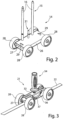
- FIG 2 shows a perspective view of the guide carriage 14.
- the guide carriage 14 comprises a chassis 26, on which two spaced-apart axles 27 for receiving rollers 28 are guided. Two rollers 28 are provided on each axle 27 . These are arranged at a distance from one another.
- the guide 15 is provided between the axes 27 .
- This guide 15 preferably consists of two guide rods 16. These can be detachably fastened to the chassis 26 and/or can also be variable in length.
- an insertion bevel is preferably attached.
- the guide rods 16 are provided eccentrically on the chassis 26 . These are preferably positioned adjacent to a side edge of the undercarriage 26 .
- a scanning element 31 is provided between the guide rods 16 of the guide 15 .
- This scanning element 31 is spring-loaded in the chassis 26 and protrudes from the underside of the chassis 26 . As a result, the positioning of the guide carriage 14 on the outer circumference 13 of the tube 12 is scanned. The other functions are described below.
- a fastening opening 29 is preferably provided at a front and rear end of the chassis 26 . There may be a catch to that Tension belt 22 are hooked.
- FIG 3 a perspective view of the carriage 21 is shown.
- the carriage 21 comprises an undercarriage 33.
- This undercarriage 33 in turn accommodates two axles 27 which are arranged at a distance from one another and each of which again accommodate a pair of rollers consisting of two rollers 28.
- the chassis 33 accommodates an operating handle 34 . This is aligned in the same direction as the guide 15 on the chassis 26 of the guide carriage 14 .
- the chassis 33 preferably has a lateral threading opening 36 in order to arrange the tension belt 22 in the chassis 33 in a simple manner.
- a clamping device 37 is preferably provided on the inside in the chassis 33 for fixing the tension belt 22 to the carriage 21 . This clamping device 37 can be released and locked by the operating handle 34 so that the carriage 21 is held in a defined position relative to the tension belt 22 .
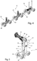
- FIG 4 is a perspective view of the separating device 11 with a guide carriage 14 and two carriages 21 and a tension belt 22 and a belt tensioning element 23 is shown.
- a selection is made in the number of carriages 21 to be used, which are dependent on the outer circumference 13 of the pipe 12. Furthermore, a distance between the carriage 21 to the guide carriage 14 and optionally between the or two or more carriages 21 to each other is determined.
- This setting of the distance is based on the fact that the guide carriage 14 and the at least one carriage 21 are preferably distributed at the same distance from one another over the outer circumference 13 of the pipe 12, so that from an operating position to the pipe 12 the separating device 13 can be rotated through 360° in a simple manner a movement along the outer circumference 13 of the tube 12 can be rotated.
- a hook, a fastener or the like is provided which after the positioning of the guide carriage 14 and the at least one carriage 21 on the outer circumference 13 of the tube 12 in a simple manner in the Mounting hole 29 in the chassis 26 of the guide carriage 14 can be suspended.
- FIG 5 a perspective view of the guide carriage 14 and the safety device 17 with the separating device 19 is shown in a receiving position 41 for the guide 15 .
- the separating device 19 is positioned relative to the guide carriage 14 .
- the separating device 19 stands still.
- a sword of the separating device 19 can rest, for example, on the outer circumference 13 of the pipe 12 .
- the safety device 17 comprises a housing 45.
- the separating device 19 is connected to the interface 46.
- a safety operating element 47 is provided opposite. To actuate the separating device 19 , the safety operating element 47 must first be actuated with one hand before the separating device 19 can be started via an on/off button 48 .
- FIG 6 a schematic view of the interface 46 of the housing 45 of the safety device 17 is shown.
- the arrangement of the housing 45 with its guide receptacles 49 which encompass the guide rods 16 is detected by a sensor element 51 .
- This detection of the position by the sensor element 51 advantageously represents a first condition for the start of the separating device 19.
- the safety operating element 47 comprises a handle 53 which is mounted so that it can be displaced in the longitudinal direction relative to a control axis 54 .
- a driver 55 which can be pivoted between preferably three stops 56 .
- the driver 55 acts on a plunger 57 which in turn actuates a sensor element 58 at the opposite end of the driver 55 .
- To activate the sensor element 58 is, for example, about the handle 53 requires a pushing or pushing movement as the first movement action. After a pushing or pushing movement, the driver 55 is in an activation position relative to the plunger 57, as shown in figure 8 is shown. A subsequent rotary movement of the handle 53 moves the plunger 57 downwards to activate the sensor element 58 .
- the tube 12 is punctured.
- the housing 45 of the safety device 17 is moved along the guide 15 into a disconnection position 61 .
- This separation position 61 of the safety device 17 from the guide carriage 14 is in figure 12 and enlarged in figure 10 shown in a side view. It also shows that the sensor element 51, which is assigned to the guide receptacle 49, is still activated. The sensor element 58 is activated. In addition, another sensor element 63 is activated, which detects the position of the scanning element 31 . This rests with a contact surface 32, for example in the form of a mushroom head, on the outer circumference 13 and has been moved to an upper position relative to the chassis 26, so that the scanning element 31 activates the sensor element 63. The safety device 17 can be transferred to a locked separating position, so that the safety device 17 with the separating device 19 does not detach itself from the guide carriage 14 .
- the safety operating element 47 can be released and the separating device 19 remains activated. If there is only one signal from the separating device 19 in the separating position 61, the separating device 19 is shut down.
- FIG 11 is a schematic end view of the tube 12 with the arranged thereon separating device 11 shown.
- the functions and steps described above for the figures 5 and 6 take place when the safety device 17 with the separating device 19 is placed on the guide carriage 14. Subsequently, in the in figure 11 shown position of the separator 19, the further steps according to Figures 7 to 10 carried out.
- the separating position 61 of the separating device 19 is in figure 12 shown.
- the safety device 17 is held secured to the guide carriage 14 in this position, and the separating device 19 remains activated. Subsequently, the separating device 11 rotates about a longitudinal axis of the tube 12.
- This end view according to FIG figure 12 It can be seen that a single lateral position by the operator is sufficient to successively grip the guide carriage and the carriages 21, rotate the separating device 11 once by 360° and make a complete separating cut.
Landscapes
- Life Sciences & Earth Sciences (AREA)
- Forests & Forestry (AREA)
- Engineering & Computer Science (AREA)
- Mechanical Engineering (AREA)
- Automatic Assembly (AREA)
Description
- Die Erfindung betrifft eine Trenneinrichtung für Rohre, insbesondere Kunststoffrohre, sowie ein Verfahren zum Trennen eines Rohrabschnitts von einem Rohr. Das Dokument
DE-A-102011080450 offenbart eine Trenneinrichtung für Rohre, insbesondere Kunststoffrohre, - mit einem Führungswagen, der Laufrollen zum Abrollen an einem Außenumfang eines Rohres aufweist, - mit einer auf dem Führungswagen vorgesehenen Führung, - mit einer Sicherheitseinrichtung, - mit einem Spanngurt, der an dem Führungswagen befestigbar ist, und- mit einem Gurtspannelement, sodass der Führungswagen an einem Außenumfang des Rohres durch den Spanngurt anliegend und fixiert gehalten ist. - Das Trennen von im Durchmesser großen Kunststoffrohren, die aus einem Vollmaterial oder einem Innen- und Außenrohr gefüllt mit einer Isolation bestehen, erfordert, dass die Trenneinrichtung entlang einer Trennstrecke am Außenumfang des Rohres um 360° geführt und gehalten werden muss. Oftmals besteht das Problem, dass während dem Einbringen des Trennschnitts in das Kunststoffrohr eine Zugänglichkeit von nur einer Seite gegeben ist, sodass die gegenüberliegende Seite nicht mehr freihändig getrennt werden kann. Zu diesem Zweck werden Trenneinrichtungen, wie beispielsweise eine Kreissäge über eine Kette, geführt, die um das Kunststoffrohr gelegt wird. Diese Ketten sind in der Länge schwierig auf den Umfang des Kunststoffrohres einzustellen sowie deren Enden zu verbinden. Darüber hinaus ist eine komplizierte Anbindung an die Trenneinrichtung beziehungsweise die Kreissäge erforderlich.
- Der Erfindung liegt die Aufgabe zugrunde, eine Trenneinrichtung für Rohre, insbesondere Kunststoffrohre, mit einem großen Durchmesser zu schaffen, welche eine einfache und sichere Handhabung sowie Anpassung an verschiedene Rohrdurchmesser ermöglicht.
- Diese Aufgabe wird durch eine Trenneinrichtung für Rohre gelöst, welche einen Führungswagen umfasst, der Laufrollen zum Abrollen auf einem Außenumfang des Rohres aufweist. Auf dem Führungswagen ist eine Führung vorgesehen, die in entgegengesetzter Richtung zum Außenumfang des Rohres weist. Des Weiteren ist eine Sicherheitseinrichtung vorgesehen, welche eine Führungsaufnahme aufweist, durch welche die Sicherheitseinrichtung zur Führung am Laufwagen geführt ist und welche eine Anschlussschnittstelle aufweist, an die eine Trennvorrichtung anschließbar ist. Des Weiteren ist zumindest ein Laufwagen vorgesehen. Der zumindest eine Laufwagen und der Führungswagen sind durch einen Spanngurt miteinander verbunden. Über ein Gurtspannelement zum Spannen des Spanngurtes werden der Führungswagen und der zumindest eine Laufwagen an einem Außenumfang des Rohres anliegend fixiert und gehalten. Durch diese Trenneinrichtung ist nach dem Einstechen der Trennvorrichtung in das Kunststoffrohr eine einfache Handhabung der Trenneinrichtung von einer Position zum Kunststoffrohr ermöglicht. Durch eine Bedienperson kann der Führungswagen und der zumindest eine Laufwagen in einer radialen Schnittebene umlaufend zum zu schneidenden Rohr, insbesondere Kunststoffrohr, betätigt werden. Beispielsweise kann über die erste Hälfte des Umfanges der Führungswagen durch eine Fahrbewegung entlang des Außenumfangs des Rohres betätigt werden und darauffolgend, sofern nur ein weiterer Laufwagen vorgesehen ist, dieser Laufwagen um weitere 180° verfahren werden, sodass daraufhin der Führungswagen mit der Trennvorrichtung einmal um 360° herumgeführt ist. Anschließend ist der Trennschnitt eingebracht und ein Rohrabschnitt von dem Rohr abgetrennt.
- Des Weiteren weist bevorzugt der Führungswagen ein Fahrwerk auf, an welchem beabstandet zwei Achsen zur Aufnahme von Laufrollen vorgesehen sind. Vorzugsweise sind zwei Paar Laufrollen zur verkippungsfreien Führung des Führungswagens vorgesehen. Zwischen den Achsen ist bevorzugt die Führung zur Aufnahme der Trennvorrichtung vorgesehen. Diese Führung erstreckt sich bevorzugt entgegengesetzt zur Abrollebene der Laufrollen. Insbesondere ist diese Führung außermittig zum Fahrwerk und vorzugsweise mittig zu dem Paar Laufrollen ausgerichtet, sodass ein Trennschnitt durch die Trennvorrichtung zwischen zwei äußeren Laufrollen am Fahrwerk des Führungswagens ermöglicht ist.
- Nach einer weiteren vorteilhaften Ausführungsform des Führungswagens ist die Führung aus zumindest zwei, vorzugsweise in der Länge veränderbare und/oder lösbare, am Fahrwerk angeordnete Führungsstangen ausgebildet. Zum einen kann durch die lösbare Anordnung ein geringes Transportvolumen ermöglicht sein. Zum anderen können durch die veränderbare Länge unterschiedliche Trennvorrichtungen mit verschieden langen Trennschwertern in Anpassung an die Größe und/oder Dicke der Wandung der Rohre eingesetzt werden.
- Bevorzugt ist am Fahrwerk des Führungswagens ein relativ zum Fahrwerk verschiebbares Abtastelement vorgesehen, welches sich zwischen den Laufrollen sowohl in Richtung auf den Außenumfang des Rohres als auch in entgegengesetzter Richtung entlang der Führung erstreckt. Dieses Abtastelement ist als Sicherheitselement vorgesehen. Sobald das Abtastelement eine vorgegebene Eintauchtiefe zwischen den Führungen aufweist, kann der Betrieb der Trennvorrichtung während dem Drehen der gesamten Trenneinrichtung entlang des Außenumfangs des Rohres aufrechterhalten werden. Sollte sich der Führungswagen lösen, steuert das Sicherheitselement ein Stillsetzen der Trennvorrichtung an.
- Vorteilhafterweise greift der Spanngurt durch Haken den Führungswagen, vorzugsweise am Fahrwerk, an. Alternativ kann der Spanngurt an oder durch das Fahrwerk geführt gehalten und beispielsweise am Laufwagen eingehängt werden. Diese Ausbildung ermöglicht eine schnelle Einrichtung der Trenneinrichtung für einen nachfolgenden Trenn- oder Schneidprozess.
- Der zumindest eine Laufwagen der Trenneinrichtung weist bevorzugt ein Fahrgestell auf, an welchem beabstandet zwei Achsen zur Aufnahme der Laufrollen vorgesehen sind und vorzugsweise zwischen den Achsen ein Betätigungsgriff am Fahrwerk angeordnet ist. Dadurch können die Trenneinrichtungen in einfacher Weise entlang des Außenumfangs des Rohres verfahren werden.
- Das Fahrgestell des Laufwagens ermöglicht gemäß einer bevorzugten Ausführungsform, dass der Spanngurt hindurchführbar ist. Des Weiteren ist bevorzugt durch den Betätigungsgriff am Fahrgestell des Laufwagens eine Klemmvorrichtung zur Fixierung des Spanngurts zum Fahrgestell ausgebildet. Somit sind kurze Rüstzeiten möglich.
- Die Sicherheitseinrichtung der Trenneinrichtung umfasst vorteilhafterweise ein Gehäuse, in welchem die Führungsaufnahmen vorgesehen sind und/oder in welchen zumindest ein Sensorelement zur Sicherheitsabfrage angeordnet ist. Diese Sicherheitseinrichtung ermöglicht und überwacht zum einen das Aufnehmen der Trennvorrichtung und die Positionierung der Trennvorrichtung zum Führungswagen, bevor ein Trennschnitt gesetzt wird und zum anderen die Einnahme der Trennposition, in welcher die Trennvorrichtung in schneidendem Eingriff zum Rohr ist. Durch das zumindest eine Sicherheitselement sind zumindest diese Positionen überwachbar.
- In oder an dem Gehäuse der Sicherungseinrichtung ist zumindest ein Sensorelement zur Abfrage einer Aufsetzposition der Führungsaufnahmen an der Führung vorgesehen. Dieses Sensorelement kann mit weiteren Sensorelementen, insbesondere mit einer Ein-/Aus-Taste der Trennvorrichtung, gekoppelt sein, sodass erst nach Erkennen der Aufsetzposition eine Freigabe der Ein-/Aus-Taste der Trennvorrichtung ermöglicht wird.
- An dem Gehäuse der Sicherheitseinrichtung und deren Schnittstelle zur Aufnahme der Trennvorrichtung zugeordnet ist bevorzugt ein weiteres Sicherheitsbedienelement vorgesehen. Dieses Sicherheitsbedienelement ist mit der Ein-/Aus-Taste der Trennvorrichtung gekoppelt. Somit ist bevorzugt eine Zweihandbedienung zum Start der Trennvorrichtung vorgesehen.
- Das Sicherheitsbedienelement kann gemäß einer bevorzugten Ausführungsform durch eine Kombination aus wenigstens zwei Betätigungsaktionen aktivierbar sein. Bevorzugt sind eine Zieh- oder Drückbewegung und eine Dreh- oder Schiebebewegung miteinander kombinierbar. Erst nach einer wenigstens zweifachen Betätigung in unterschiedlichen Betätigungsrichtungen wird ein Schaltkontakt freigegeben und daraufhin erst das Einschalten durch die Ein- und Aus-Taste der Trennvorrichtung ermöglicht.
- Des Weiteren ist bevorzugt die Sicherheitseinrichtung mit der angetriebenen Trennvorrichtung aus der Aufsetzposition entlang der Führung in eine Trennposition überführbar. Bei diesem Übergang erfolgt ein Einstechen der Trennvorrichtung in das Kunststoffrohr als erste Trennphase für das Abtrennen eines Rohrabschnitts.
- An oder in dem Gehäuse der Sicherheitseinrichtung ist ein weiteres Sensorelement vorgesehen, welches durch das Abtastelement am Fahrwerk des Führungswagens beim Aufliegen des Führungswagens auf den Außenumfang des Rohres betätigt wird und die Einnahme der Schneidposition der Trennvorrichtung zur Führung am Führungswagen arretiert.
- Bevorzugt sind die vorgenannten Sensorelemente und das Sicherheitsbedienelement in der Sicherheitseinrichtung derart aufeinander abgestimmt, dass eine aufeinanderfolgende Abfrage der Signale vorgesehen ist und beim Erfassen aller Signale die Trennvorrichtung nicht selbständig stillsetzt. Dadurch können erhöhte Sicherheitsanforderungen durch diese Trennvorrichtung erfüllt werden.
- Gemäß einer bevorzugten Ausführungsform der Trennvorrichtung ist die an der Sicherheitseinrichtung angeordnete Trennvorrichtung als eine Kettensäge, Stichsäge oder Kreissäge ausgebildet. In Abhängigkeit der Trennaufgabe können dabei verschieden lange Schwerter eingesetzt werden, um die Wandstärken zu schneiden. Des Weiteren kann die Trennvorrichtung mit einem Akkumulator betrieben werden. Durch die kabellose Betätigung wird die Handhabung des Weiteren erleichtert.
- Die der Erfindung zugrundeliegende Aufgabe wird des Weiteren durch ein Verfahren zum Trennen eines Rohrabschnittes von einem Rohr mit einer Trenneinrichtung nach einer der vorbeschriebenen Ausführungsformen gelöst. Dabei sind folgende Schritte vorgesehen:
- Der Führungswagen und der zumindest eine Laufwagen werden mit einem Spanngurt verbunden, wobei ein offenes Ende des Spanngurtes verbleibt. Anschließend werden der Führungswagen und der zumindest eine Laufwagen auf den Außenumfang des Rohres positioniert. Das offene Ende des Spanngurtes wird bevorzugt an dem Führungswagen oder Laufwagen befestigt. Der Spanngurt kann durch ein Gurtspannelement gespannt werden. Der Führungswagen und der zumindest eine Laufwagen sind anliegend am Außenumfang des Rohres gehalten. Darauffolgend wird die Sicherheitseinrichtung mit der Trennvorrichtung auf der Führung des Führungswagens positioniert sowie das Sicherheitsbedienelement der Sicherheitseinrichtung und darauffolgend die Ein-/Aus-Taste der Trennvorrichtung betätigt. Die Trennvorrichtung wird von einer Aufnahmeposition in radialer Richtung zur Längsmittelachse des Rohres entlang der Führung bewegt, wodurch ein Einstich in das Rohr erfolgt, bis die Trennvorrichtung in die Schneidposition übergeführt wird. In der Schneidposition fixiert ein Rastbolzen die Maschinenposition. Anschließend wird der Führungswagen und darauffolgend der zumindest eine Laufwagen entlang des Außenumfangs einmal um 360° gedreht. Bevorzugt ist eine zusätzliche Führung zum Positionieren der Trenneinrichtung zur Trennstelle nicht erforderlich. Im Anschluss an eine Drehung der Trenneinrichtung um 360° ist der Rohrabschnitt abgetrennt. Die Demontage der Trenneinrichtung kann in umgekehrter Reihenfolge erfolgen. Alternativ kann auch ein Lösen des Gurtspannelementes und darauffolgend ein Lösen des Spanngurtes von dem Führungswagen oder Laufwagen vorgesehen sein, sodass die gesamte Trenneinrichtung vom Rohr abnehmbar ist.
- Die Erfindung sowie weitere vorteilhafte Ausführungsformen und Weiterbildungen derselben werden im Folgenden anhand der in den Zeichnungen dargestellten Beispiele näher beschrieben und erläutert. Die der Beschreibung und den Zeichnungen zu entnehmenden Merkmale können einzeln für sich oder zu mehreren in beliebiger Kombination erfindungsgemäß angewandt werden. Es zeigen:
-
Figur 1 eine perspektivische Ansicht einer auf einem Rohr vorgesehenen Trenneinrichtung, -
Figur 2 eine perspektivische Ansicht eines Führungswagens der Trenneinrichtung gemäßFigur 1 , -
Figur 3 eine perspektivische Ansicht eines Laufwagens der Trenneinrichtung gemäßFigur 1 , -
Figur 4 eine perspektivische Ansicht eines Führungswagens und Laufwagens in Vorbereitung auf einen Trennschnitt, -
Figur 5 eine perspektivische Ansicht zur Positionierung einer Trennvorrichtung auf dem Führungswagen für einen Einstich in das Rohr, -
Figur 6 eine erste schematische Ansicht auf eine Sicherheitseinrichtung in einer Aufnahmeposition zum Führungswagen gemäßFigur 5 , -
Figuren 7 bis 9 schematische Ansichten eines Sicherheitsbedienelementes für eine Zweihandbedienung zum Start der Trennvorrichtung, -
Figur 10 eine schematische Seitenansicht der Sicherheitseinrichtung mit der Trennvorrichtung in einer Trennposition, -
Figur 11 eine schematische Ansicht von vorne auf eine Trenneinrichtung vor Beginn eines Trennprozesses, und -
Figur 12 eine schematische Ansicht von vorne auf die Trenneinrichtung während eines Trennprozesses. - In
Figur 1 ist eine perspektivische Ansicht einer Trenneinrichtung 11 dargestellt. Diese Trenneinrichtung 11 ist auf einem zu trennenden Rohr 12 montiert. Bei den zu trennenden Rohren 12 kann es sich beispielsweise um Kunststoffrohre mit einem großen Durchmesser handeln. Für eine Bedienperson ist es nicht möglich, eine Trennvorrichtung 19, wie beispielsweise eine Kettensäge, freihändig aus einer Bedienposition zum Rohr einmal vollständig um 360° entlang des Außenumfanges zu führen. Des Weiteren können solche Rohre 12, insbesondere Kunststoffrohre, aus einem Vollmaterial oder aus einem Innen- und Außenrohr gebildet sein, dessen Wandung mit einem Isoliermaterial, wie beispielsweise einem Schaum, gefüllt ist. Die Außenund Innenwand des Rohres 12 bestehen bevorzugt aus Kunststoff. Diese Trenneinrichtung 11 umfasst einen Führungswagen 14. Über eine Führung 15 am Führungswagen 14 ist eine Sicherheitseinrichtung 17 aufgenommen und geführt. Zusätzlich wird die Trennvorrichtung 19 auf der Führung 15 vor dem Rausfallen durch einen Rastbolzen gesichert und in der Endposition fixiert. Diese Sicherheitseinrichtung 17 nimmt wiederum die Trennvorrichtung 19 über eine Schnittstelle auf. Bei dieser Trennvorrichtung 19 kann es sich um eine Kettensäge handeln, ebenso kann eine Kreissäge oder Stichsäge vorgesehen sein. Die Trennvorrichtung 19 ist bevorzugt mit einem Akkumulator betrieben. Der Einsatz einer Kettensäge weist den Vorteil auf, dass eine Betätigungsrichtung der Trenneinrichtung 11, wie nachfolgend noch beschrieben sein wird, in beide Drehrichtungen zum Außenumfang des Rohres 12 erfolgen kann. - Des Weiteren umfasst die Trenneinrichtung 11 zumindest einen Laufwagen 21. Der Führungswagen 14 und der zumindest eine Laufwagen 21 sind durch einen Spanngurt 22 miteinander verbunden und fest anliegend zum Außenumfang 13 des Rohres 12 positioniert. Bevorzugt ist ein Gurtspannelement 23 vorgesehen, um nach dem Positionieren des Führungswagens 14 und des zumindest einen Laufwagens 21 eine fixierte Anordnung zum Außenumfang 13 des Rohres 12 zu erzeugen. Diese fixierte Anordnung ermöglicht dennoch, dass die gesamte Trenneinrichtung 11 innerhalb einer radialen Ebene entlang des Außenumfangs des Rohres 12 verfahrbar ist. Der Spanngurt 22 kann dabei auch teilweise auf dem Außenumfang 13 des Rohres 12 aufliegen.
-
Figur 2 zeigt eine perspektivische Ansicht des Führungswagens 14. Der Führungswagen 14 umfasst ein Fahrwerk 26, an welchem zwei im Abstand zueinander angeordnete Achsen 27 zur Aufnahme von Laufrollen 28 geführt sind. An jeder Achse 27 sind zwei Laufrollen 28 vorgesehen. Diese sind im Abstand zueinander angeordnet. Zwischen den Achsen 27 ist die Führung 15 vorgesehen. Diese Führung 15 besteht bevorzugt aus zwei Führungsstangen 16. Diese können lösbar am Fahrwerk 26 befestigt und/oder auch in der Länge veränderbar sein. Am oberen Ende der Führungsstangen 16 ist bevorzugt eine Einführschräge angebracht. Die Führungsstangen 16 sind außermittig am Fahrwerk 26 vorgesehen. Bevorzugt sind diese an einer Seitenkante des Fahrwerks 26 angrenzend positioniert. - Zwischen den Führungsstangen 16 der Führung 15 ist ein Abtastelement 31 vorgesehen. Dieses Abtastelement 31 ist federgelagert im Fahrwerk 26 angeordnet und steht gegenüber einer Unterseite des Fahrwerks 26 hervor. Dadurch wird die Positionierung des Führungswagens 14 auf dem Außenumfang 13 des Rohres 12 abgetastet. Die weitere Funktion wird nachfolgend noch beschrieben.
- An einem vorderen und hinteren Ende des Fahrwerkes 26 ist bevorzugt eine Befestigungsöffnung 29 vorgesehen. Daran kann ein Haken am Spanngurt 22 eingehängt werden.
- In
Figur 3 ist eine perspektivische Ansicht des Laufwagens 21 dargestellt. Der Laufwagen 21 umfasst ein Fahrgestell 33. Durch dieses Fahrgestell 33 werden wiederum zwei im Abstand zueinander angeordnete Achsen 27 aufgenommen, die jeweils wieder ein Laufrollenpaar bestehend aus zwei Laufrollen 28 aufnehmen. Das Fahrgestell 33 nimmt einen Betätigungsgriff 34 auf. Dieser ist in gleicher Richtung wie die Führung 15 am Fahrwerk 26 des Führungswagens 14 ausgerichtet. - Das Fahrgestell 33 weist bevorzugt eine seitliche Einfädelöffnung 36 auf, um in einfacher Weise den Spanngurt 22 im Fahrgestell 33 anzuordnen. Zur Fixierung des Spanngurtes 22 zum Laufwagen 21 ist bevorzugt innenliegend im Fahrgestell 33 eine Klemmeinrichtung 37 vorgesehen. Diese Klemmeinrichtung 37 kann durch den Betätigungsgriff 34 lösbar und arretierbar sein, sodass der Laufwagen 21 in einer definierten Position zum Spanngurt 22 gehalten ist.
- In
Figur 4 ist eine perspektivische Ansicht auf die Trenneinrichtung 11 mit einem Führungswagen 14 und zwei Laufwägen 21 sowie einem Spanngurt 22 und einem Gurtspannelement 23 dargestellt. In Vorbereitung auf die Aufspannung der Trenneinrichtung 11 auf das Rohr 12 erfolgt eine Auswahl in der Anzahl der einzusetzenden Laufwägen 21, die vom Außenumfang 13 des Rohres 12 abhängig sind. Des Weiteren wird auch ein Abstand zwischen dem Laufwagen 21 zum Führungswagen 14 und gegebenenfalls zwischen dem oder zwei oder mehreren Laufwagen 21 zueinander bestimmt. Diese Einstellung des Abstandes beruht darauf, dass der Führungswagen 14 und der zumindest eine Laufwagen 21 bevorzugt im gleichen Abstand zueinander über den Außenumfang 13 des Rohres 12 verteilt sind, sodass aus einer Bedienposition zum Rohr 12 die Trenneinrichtung 13 einmal um 360° in einfacher Weise durch eine Verfahrbewegung entlang des Außenumfanges 13 des Rohrs 12 gedreht werden kann. An einem freien Ende 38 des Spanngurtes 22 ist ein Haken, ein Verschluss oder dergleichen vorgesehen, der nach dem Positionieren des Führungswagens 14 und dem zumindest einen Laufwagen 21 auf dem Außenumfang 13 des Rohres 12 in einfacher Weise in die Befestigungsöffnung 29 im Fahrwerk 26 des Führungswagens 14 einhängbar ist. - In
Figur 5 ist perspektivisch eine Ansicht auf den Führungswagen 14 sowie der Sicherheitseinrichtung 17 mit der Trennvorrichtung 19 in einer Aufnahmeposition 41 zur Führung 15 dargestellt. Nach dem Aufspannen des Führungswagens 14 und des zumindest einen Laufwagens 21 auf dem Außenumfang 13 des Rohres 12 wird die Trennvorrichtung 19 zum Führungswagen 14 positioniert. In dieser Aufnahmeposition 41 steht die Trennvorrichtung 19 still. Ein Schwert der Trennvorrichtung 19 kann beispielsweise am Außenumfang 13 des Rohres 12 aufliegen. Die Sicherheitseinrichtung 17 umfasst ein Gehäuse 45. An der Schnittstelle 46 ist die Trennvorrichtung 19 angebunden. Gegenüberliegend ist ein Sicherheitsbedienelement 47 vorgesehen. Zur Betätigung der Trennvorrichtung 19 ist zunächst mit einer Hand das Sicherheitsbedienelement 47 zu betätigen, bevor über eine Ein-/Aus-Taste 48 die Trennvorrichtung 19 gestartet werden kann. - In
Figur 6 ist eine schematische Ansicht auf die Schnittstelle 46 des Gehäuses 45 der Sicherheitseinrichtung 17 dargestellt. Die Anordnung des Gehäuses 45 mit deren Führungsaufnahmen 49, welche die Führungsstangen 16 umgreifen, wird durch ein Sensorelement 51 erfasst. Diese Erfassung der Position durch das Sensorelement 51 stellt vorteilhafterweise eine erste Bedingung für den Start der Trennvorrichtung 19 dar. - Des Weiteren ist vorteilhafterweise die Zweihandbedienung durch das Sicherheitsbedienelement 47 vorgesehen. In den
Figuren 7 bis 9 sind die Komponenten und die Funktionsweise des Sicherheitsbedienelementes 47 dargestellt. Das Sicherheitsbedienelement 47 umfasst einen Handgriff 53, der in Längsrichtung zu einer Steuerachse 54 verschiebbar gelagert ist. Am Ende der Steuerachse 54 ist ein Mitnehmer 55 vorgesehen, der zwischen vorzugsweise drei Anschlägen 56 schwenkbeweglich ist. Der Mitnehmer 55 wirkt auf einen Stößel 57, der wiederum am gegenüberliegenden Ende des Mitnehmers 55 ein Sensorelement 58 betätigt. Zur Aktivierung des Sensorelementes 58 ist beispielsweise über den Handgriff 53 eine Druck- oder Schiebebewegung als erste Bewegungsaktion erforderlich. Nach einer Druck- oder Schiebebewegung ist der Mitnehmer 55 in einer Aktivierungsposition zum Stößel 57, wie dies inFigur 8 dargestellt ist. Durch eine darauffolgende Drehbewegung des Handgriffs 53 wird der Stößel 57 nach unten zur Aktivierung des Sensorelementes 58 bewegt. - Bei Einnahme dieser in
Figur 9 dargestellten Schaltposition des Sensorelementes 58 wird darauffolgend die Ein-/Aus-Taste 48 betätigt und die Trennvorrichtung 19 aktiviert. Diese Situation ist beispielsweise in denFiguren 10 und11 dargestellt. - In einer darauffolgenden ersten Phase erfolgt ein Einstich in das Rohr 12. Das Gehäuse 45 der Sicherheitsvorrichtung 17 wird entlang der Führung 15 in eine Trennposition 61 übergeführt.
- Diese Trennposition 61 der Sicherheitsvorrichtung 17 zum Führungswagen 14 ist in
Figur 12 und vergrößert inFigur 10 in einer Seitenansicht dargestellt. Daraus geht des Weiteren hervor, dass das Sensorelement 51, welches der Führungsaufnahme 49 zugeordnet ist, weiter aktiviert ist. Das Sensorelement 58 ist aktiviert. Darüber hinaus ist ein weiteres Sensorelement 63 aktiviert, welches die Position des Abtastelementes 31 erfasst. Dieses liegt mit einer Auflagefläche 32, beispielsweise in Form eines Pilzkopfes, auf dem Außenumfang 13 auf, und wurde in eine obere Position zum Fahrwerk 26 verfahren, sodass das Abtastelement 31 das Sensorelement 63 aktiviert. Die Sicherheitseinrichtung 17 kann in eine arretierte Trennposition übergeführt sein, sodass sich die Sicherheitseinrichtung 17 mit der Trennvorrichtung 19 nicht selbständig vom Führungswagen 14 löst. Sobald von den Sensorelementen 51, 58, 63 ein Signal ausgegeben ist, dass die zu überwachenden Positionen eingenommen sind, kann das Sicherheitsbedienelement 47 gelöst werden, und die Trennvorrichtung 19 bleibt aktiviert. Sofern nur ein Signal der Trennvorrichtung 19 in der Trennposition 61 nicht vorhanden ist, wird die Trennvorrichtung 19 stillgesetzt. - In
Figur 11 ist eine schematische Stirnansicht auf das Rohr 12 mit der darauf angeordneten Trennvorrichtung 11 dargestellt. Die vorbeschriebenen Funktionen und Schritte zu denFiguren 5 und6 finden beim Aufsetzen der Sicherheitseinrichtung 17 mit der Trennvorrichtung 19 auf den Führungswagen 14 statt. Darauffolgend werden in der inFigur 11 dargestellten Position der Trennvorrichtung 19 die weiteren Schritte gemäß denFiguren 7 bis 10 durchgeführt. Die Trennposition 61 der Trennvorrichtung 19 ist inFigur 12 dargestellt. Die Sicherheitseinrichtung 17 ist zum Führungswagen 14 in dieser Position gesichert gehalten, und die Trennvorrichtung 19 bleibt aktiviert. Anschließend erfolgt eine Drehbewegung der Trenneinrichtung 11 um eine Längsachse des Rohres 12. Durch diese Stirnansicht gemäßFigur 12 ist ersichtlich, dass eine einzige seitliche Position durch die Bedienperson genügt, um aufeinanderfolgend am Führungswagen und den Laufwägen 21 anzugreifen, die Trenneinrichtung 11 einmalig um 360° zu drehen und einen vollständigen Trennschnitt einzubringen.
Claims (16)
- Trenneinrichtung für Rohre, insbesondere Kunststoffrohre,- mit einem Führungswagen (14), der Laufrollen (28) zum Abrollen an einem Außenumfang (13) eines Rohres (12) aufweist,- mit einer auf dem Führungswagen (14) vorgesehenen Führung (15),- mit einer Sicherheitseinrichtung (17), welche zumindest eine Führungsaufnahme (49) aufweist, durch welche die Sicherheitseinrichtung (17) zur Führung (15) anordenbar ist, und welche eine Schnittstelle (46) aufweist, an die eine Trennvorrichtung (19) anschließbar ist,- mit zumindest einem Laufwagen (21),- mit einem Spanngurt (22), der an dem Führungswagen (14) und zumindest einem Laufwagen (21) befestigbar ist, und- mit einem Gurtspannelement (23), sodass der Führungswagen (14) und der zumindest eine Laufwagen (21) an einem Außenumfang (13) des Rohres (12) durch den Spanngurt (22) anliegend und fixiert gehalten sind.
- Trenneinrichtung nach Anspruch 1, dadurch gekennzeichnet, dass der Führungswagen (14) ein Fahrwerk (26) aufweist, an welchem beabstandet zwei Achsen (27) zur Aufnahme von Laufrollen (28) vorgesehen sind und zwischen den Achsen (27) die Führung (15) zur Aufnahme der Trenneinrichtung (19) vorgesehen ist, welche vorzugsweise zu einer Seite des Fahrwerks (26) ausgerichtet ist.
- Trenneinrichtung nach Anspruch 2, dadurch gekennzeichnet, dass die Führung (15) aus zumindest zwei, vorzugsweise in der Länge veränderbare und/oder lösbar am Fahrwerk (26) angeordnete, Führungsstangen (16) ausgebildet ist.
- Trenneinrichtung nach Anspruch 2 oder 3, dadurch gekennzeichnet, dass der Führung (15) am Fahrwerk (26) zugeordnet ein relativ zum Fahrwerk (26) verschiebbares Abtastelement (31) vorgesehen ist, welches sich zwischen den Laufrollen (28) sowohl in Richtung auf den Außenumfang (13) des Rohres (12) als auch in entgegengesetzter Richtung entlang der Führung (15) erstreckt.
- Trenneinrichtung nach einem der Ansprüche 2 bis 4, dadurch gekennzeichnet, dass der Spanngurt (22) am Fahrwerk (26) des Führungswagens (14) einhängbar ist, oder dass der Spanngurt (22) an oder durch das Fahrwerk (26) entlangführbar oder hindurchführbar gehalten ist.
- Trenneinrichtung nach einem der vorhergehenden Ansprüche, dadurch gekennzeichnet, dass der Laufwagen (21) ein Fahrgestell (33) aufweist, an welchem beabstandet zueinander zwei Achsen (27) zur Aufnahme von Laufrollen (28) vorgesehen sind und zwischen den Achsen (27) ein Betätigungsgriff (34) vorgesehen ist, der sich vorzugsweise in entgegengesetzter Richtung zur Abroll-ebene der Laufrollen (28) erstreckt.
- Trenneinrichtung nach Anspruch 6, dadurch gekennzeichnet, dass der Spanngurt (22) an oder in dem Fahrgestell (33) anordenbar und/oder hindurchführbar ist und vorzugsweise durch den Betätigungsgriff (34) eine Klemmvorrichtung (37) zur Fixierung des Spanngurtes (22) zum Fahrgestell (33) betätigbar ist.
- Trenneinrichtung nach einem der vorhergehenden Ansprüche, dadurch gekennzeichnet, dass die Sicherheitseinrichtung (17) ein Gehäuse (45) umfasst, in welchem die Führungsaufnahmen (49) vorgesehen sind und/oder in welchem zumindest ein Sensorelement (51, 58, 63) angeordnet ist.
- Trenneinrichtung nach Anspruch 8, dadurch gekennzeichnet, dass an oder im Gehäuse (45) der Sicherheitseinrichtung (17) das zumindest eine Sensorelement (51) zur Abfrage einer Aufnahmeposition (41) der Sicherheitseinrichtung (17) auf der Führung (15) vorgesehen ist.
- Trenneinrichtung nach Anspruch 8 oder 9, dadurch gekennzeichnet, dass an oder im Gehäuse (45) der Sicherheitseinrichtung (17) und der Schnittstelle (46) zur Aufnahme der Trenneinrichtung (19) zugeordnet ein Sicherheitsbedienelement (47) für eine Zweihandbedienung zum Start der Trennvorrichtung (19) vorgesehen ist.
- Trenneinrichtung nach Anspruch 10, dadurch gekennzeichnet, dass das Sicherheitsbedienelement (47) durch eine Kombination von wenigstens zwei Betätigungsaktionen aktivierbar ist, und vorzugsweise eine Zieh- oder Drückbewegung und eine Dreh- oder Schiebebewegung miteinander kombinierbar sind, bevor das Sensorelement (58) betätigbar und eine Betätigung einer Ein-/Aus-Taste (48) der Trennvorrichtung (19) gegeben ist.
- Trenneinrichtung nach einem der Ansprüche 8 bis 11, dadurch gekennzeichnet, dass die Sicherheitseinrichtung (17) mit der angetriebenen Trennvorrichtung (19) aus der Aufnahmeposition (41) entlang der Führung (15) verfahrbar in eine Trennposition (61) überführbar ist.
- Trenneinrichtung nach einem der Ansprüche 8 bis 12, dadurch gekennzeichnet, dass an oder im Gehäuse (45) der Sicherheitseinrichtung (46) ein weiteres Sensorelement (63) vorgesehen ist, welche durch das Abtastelement (31) am Führungswagen (15) beim Aufliegen des Führungswagens (15) auf dem Außenumfang (13) des Rohres (12) und bei Einnahme der Trennposition (61) der Sicherheitseinrichtung (17) aktivierbar ist und vorzugsweise die Sicherheitseinrichtung (17) in dieser Trennposition (61) zum Führungswagen (14) arretierbar ist.
- Trenneinrichtung nach einem der vorhergehenden Ansprüche, dadurch gekennzeichnet, dass nach einer aufeinanderfolgenden Abfrage von Signalen der Sensorelemente (51, 58, 63) und der Abfrage des Signals von den Abtastelementen (31) das Vorhandensein der Sicherheitseinrichtung (17) in der Trennposition (61) erfassbar ist und beim Erfassen aller Signale die Trenneinrichtung (19) sich nicht selbständig stillsetzt.
- Trenneinrichtung nach einem der vorhergehenden Ansprüche, dadurch gekennzeichnet, dass die Trennvorrichtung (19) als eine Kettensäge, Stichsäge oder Kreissäge ausgebildet ist und/oder dass die Trennvorrichtung (19) mit einem Akkumulator betrieben ist.
- Verfahren zum Trennen eines Rohrabschnitts von einem Rohr (12), insbesondere Kunststoffrohr,- bei dem eine Trenneinrichtung (11) nach einem der Ansprüche 1 bis 15 eingesetzt wird,- bei dem der Führungswagen (15) und der zumindest eine Laufwagen (21) mit dem Spanngurt (22) verbunden werden,- bei dem der Führungswagen (14) und der zumindest eine Laufwagen (21) auf dem Außenumfang (13) des Rohres (12) positioniert werden,- bei dem der Spanngurt (22) an dem Führungswagen (15) oder dem zumindest einen Laufwagen (21) befestigt und durch das Gurtspannelement (23) gespannt wird,- bei dem die Sicherheitseinrichtung (17) mit der Trennvorrichtung (19) auf der Führung (15) des Führungswagens (14) positioniert und das Sicherheitsbedienelement (47) sowie darauffolgend die Ein-/Aus-Taste der Trennvorrichtung (19) betätigt wird,- bei dem die Trennvorrichtung (19) aus der Aufnahmeposition (41) in die Trennposition (61) übergeführt und die Sicherheitseinrichtung (17) zum Führungswagen (14) in der Trennposition (61) arretiert wird, und- bei dem der Führungswagen (14) und der zumindest eine Laufwagen (21) einmal um 360° entlang dem Außenumfang (13) des Rohres (12) verfahren werden.
Priority Applications (1)
| Application Number | Priority Date | Filing Date | Title |
|---|---|---|---|
| EP20213848.3A EP4011575B1 (de) | 2020-12-14 | 2020-12-14 | Trenneinrichtung für rohre sowie verfahren zum trennen eines rohrabschnitts von einem rohr mit einer solchen trenneinrichtung |
Applications Claiming Priority (1)
| Application Number | Priority Date | Filing Date | Title |
|---|---|---|---|
| EP20213848.3A EP4011575B1 (de) | 2020-12-14 | 2020-12-14 | Trenneinrichtung für rohre sowie verfahren zum trennen eines rohrabschnitts von einem rohr mit einer solchen trenneinrichtung |
Publications (2)
| Publication Number | Publication Date |
|---|---|
| EP4011575A1 EP4011575A1 (de) | 2022-06-15 |
| EP4011575B1 true EP4011575B1 (de) | 2023-06-14 |
Family
ID=73835470
Family Applications (1)
| Application Number | Title | Priority Date | Filing Date |
|---|---|---|---|
| EP20213848.3A Active EP4011575B1 (de) | 2020-12-14 | 2020-12-14 | Trenneinrichtung für rohre sowie verfahren zum trennen eines rohrabschnitts von einem rohr mit einer solchen trenneinrichtung |
Country Status (1)
| Country | Link |
|---|---|
| EP (1) | EP4011575B1 (de) |
Family Cites Families (4)
| Publication number | Priority date | Publication date | Assignee | Title |
|---|---|---|---|---|
| US2291395A (en) * | 1939-12-15 | 1942-07-28 | Nat Machine Works | Pipe cutting machine |
| JP3482516B2 (ja) * | 1999-02-22 | 2003-12-22 | 好高 青山 | 切断装置 |
| DE102011080450A1 (de) * | 2011-08-04 | 2013-02-07 | WIDOS Wilhelm Dommer Söhne GmbH | Vorrichtung zum Schneiden von großvolumigen Kunststoffrohren |
| DE102015001453A1 (de) * | 2015-02-05 | 2016-08-11 | Andreas Stihl Ag & Co. Kg | Trennvorrichtung zum Trennen eines zylindrischen Werkstücks |
-
2020
- 2020-12-14 EP EP20213848.3A patent/EP4011575B1/de active Active
Also Published As
| Publication number | Publication date |
|---|---|
| EP4011575A1 (de) | 2022-06-15 |
Similar Documents
| Publication | Publication Date | Title |
|---|---|---|
| DE2720027C3 (de) | Bindewerkzeug zum Verdrillen der freien Enden eines Bindedrahtes | |
| EP3259100A1 (de) | Wasser-abrasiv-schneidanlage | |
| EP1969945B1 (de) | Verfahren und Vorrichtung zum gesteuerten Verschliessen wenigstens eines Clips um einen füllgutfreien Zopfabschnitt zwischen zwei mit einer Hülle umschlossenen Füllgutabschnitten | |
| DE2348097B2 (de) | Vorrichtung zum Entfernen eines Wulstdrahtes aus einem Luftreifen | |
| DE102013017374A1 (de) | "Vorrichtung zum Abschälen der äußerenSchicht(en) eines Rohres oder Kabels" | |
| DE102019216572A1 (de) | Angetriebene kreissägen und zubehörteile für solche sägen | |
| EP4011575A1 (de) | Trenneinrichtung für rohre sowie verfahren zum trennen eines rohrabschnitts von einem rohr mit einer solchen trenneinrichtung | |
| DE10011909A1 (de) | Bandahle | |
| EP1642686A2 (de) | Bohrständer | |
| WO1992019501A1 (de) | Anordnung zum ordnen und binden eines langgestreckten gegenstandes, insbesondere eines kabelbaums | |
| DE2223099A1 (de) | Verfahren und vorrichtungen zur herstellung einer mechanisch schluessigen verbindung von wenigstens zwei sich an der verbindungsstelle beruehrender draehte und/ oder staebe mit hilfe eines bindedrahtes | |
| DE3238005C2 (de) | Diebstahlsicherung für Kraftfahrzeuge | |
| DE8333067U1 (de) | Vorrichtung zum setzen von befestigungselementen | |
| DE202012009996U1 (de) | Vorrichtung zum Abschälen der äußeren Schicht(en) eines Rohres oder Kabels | |
| DE3510299C1 (de) | Vorrichtung zum Abziehen einer Schiebemuffe | |
| EP0659538B1 (de) | Vorrichtung zum Anbringen von Henkeln an Behältern | |
| DE3737297A1 (de) | Verfahren zum behandeln eines drahtendes und vorrichtung hierfuer | |
| DE4107567C2 (de) | Vorrichtung zum Entkorken von Flaschen und deren Wiederverschließen mit dem gezogenen Korken | |
| EP1717067B1 (de) | Antrieb für eine Anhängerkupplung | |
| EP2620262B1 (de) | Kupplungsanordnung für eine Sicherheitsabschaltung | |
| WO1996008414A1 (de) | Verfahren und vorrichtung zum verdrillen von bindedraht | |
| DE202010008463U1 (de) | Vorrichtung zum Durchtrennen eines Rohres | |
| DE3911870A1 (de) | Markierungsvorrichtung | |
| DE2139946A1 (de) | Vorrichtung zum Gewindeschneiden an Rohren | |
| DE1229944B (de) | Bohrgestaenge-Zentriereinrichtung |
Legal Events
| Date | Code | Title | Description |
|---|---|---|---|
| PUAI | Public reference made under article 153(3) epc to a published international application that has entered the european phase |
Free format text: ORIGINAL CODE: 0009012 |
|
| STAA | Information on the status of an ep patent application or granted ep patent |
Free format text: STATUS: THE APPLICATION HAS BEEN PUBLISHED |
|
| AK | Designated contracting states |
Kind code of ref document: A1 Designated state(s): AL AT BE BG CH CY CZ DE DK EE ES FI FR GB GR HR HU IE IS IT LI LT LU LV MC MK MT NL NO PL PT RO RS SE SI SK SM TR |
|
| STAA | Information on the status of an ep patent application or granted ep patent |
Free format text: STATUS: REQUEST FOR EXAMINATION WAS MADE |
|
| 17P | Request for examination filed |
Effective date: 20220913 |
|
| RBV | Designated contracting states (corrected) |
Designated state(s): AL AT BE BG CH CY CZ DE DK EE ES FI FR GB GR HR HU IE IS IT LI LT LU LV MC MK MT NL NO PL PT RO RS SE SI SK SM TR |
|
| GRAP | Despatch of communication of intention to grant a patent |
Free format text: ORIGINAL CODE: EPIDOSNIGR1 |
|
| STAA | Information on the status of an ep patent application or granted ep patent |
Free format text: STATUS: GRANT OF PATENT IS INTENDED |
|
| RIC1 | Information provided on ipc code assigned before grant |
Ipc: B26D 7/24 19680901ALI20230111BHEP Ipc: B26D 7/00 19680901ALI20230111BHEP Ipc: B26D 3/16 19680901AFI20230111BHEP |
|
| INTG | Intention to grant announced |
Effective date: 20230127 |
|
| GRAS | Grant fee paid |
Free format text: ORIGINAL CODE: EPIDOSNIGR3 |
|
| GRAA | (expected) grant |
Free format text: ORIGINAL CODE: 0009210 |
|
| STAA | Information on the status of an ep patent application or granted ep patent |
Free format text: STATUS: THE PATENT HAS BEEN GRANTED |
|
| AK | Designated contracting states |
Kind code of ref document: B1 Designated state(s): AL AT BE BG CH CY CZ DE DK EE ES FI FR GB GR HR HU IE IS IT LI LT LU LV MC MK MT NL NO PL PT RO RS SE SI SK SM TR |
|
| REG | Reference to a national code |
Ref country code: CH Ref legal event code: EP |
|
| REG | Reference to a national code |
Ref country code: DE Ref legal event code: R096 Ref document number: 502020003773 Country of ref document: DE |
|
| REG | Reference to a national code |
Ref country code: AT Ref legal event code: REF Ref document number: 1578906 Country of ref document: AT Kind code of ref document: T Effective date: 20230715 |
|
| REG | Reference to a national code |
Ref country code: LT Ref legal event code: MG9D |
|
| REG | Reference to a national code |
Ref country code: NL Ref legal event code: MP Effective date: 20230614 |
|
| PG25 | Lapsed in a contracting state [announced via postgrant information from national office to epo] |
Ref country code: SE Free format text: LAPSE BECAUSE OF FAILURE TO SUBMIT A TRANSLATION OF THE DESCRIPTION OR TO PAY THE FEE WITHIN THE PRESCRIBED TIME-LIMIT Effective date: 20230614 Ref country code: NO Free format text: LAPSE BECAUSE OF FAILURE TO SUBMIT A TRANSLATION OF THE DESCRIPTION OR TO PAY THE FEE WITHIN THE PRESCRIBED TIME-LIMIT Effective date: 20230914 Ref country code: ES Free format text: LAPSE BECAUSE OF FAILURE TO SUBMIT A TRANSLATION OF THE DESCRIPTION OR TO PAY THE FEE WITHIN THE PRESCRIBED TIME-LIMIT Effective date: 20230614 |
|
| PG25 | Lapsed in a contracting state [announced via postgrant information from national office to epo] |
Ref country code: RS Free format text: LAPSE BECAUSE OF FAILURE TO SUBMIT A TRANSLATION OF THE DESCRIPTION OR TO PAY THE FEE WITHIN THE PRESCRIBED TIME-LIMIT Effective date: 20230614 Ref country code: NL Free format text: LAPSE BECAUSE OF FAILURE TO SUBMIT A TRANSLATION OF THE DESCRIPTION OR TO PAY THE FEE WITHIN THE PRESCRIBED TIME-LIMIT Effective date: 20230614 Ref country code: LV Free format text: LAPSE BECAUSE OF FAILURE TO SUBMIT A TRANSLATION OF THE DESCRIPTION OR TO PAY THE FEE WITHIN THE PRESCRIBED TIME-LIMIT Effective date: 20230614 Ref country code: LT Free format text: LAPSE BECAUSE OF FAILURE TO SUBMIT A TRANSLATION OF THE DESCRIPTION OR TO PAY THE FEE WITHIN THE PRESCRIBED TIME-LIMIT Effective date: 20230614 Ref country code: HR Free format text: LAPSE BECAUSE OF FAILURE TO SUBMIT A TRANSLATION OF THE DESCRIPTION OR TO PAY THE FEE WITHIN THE PRESCRIBED TIME-LIMIT Effective date: 20230614 Ref country code: GR Free format text: LAPSE BECAUSE OF FAILURE TO SUBMIT A TRANSLATION OF THE DESCRIPTION OR TO PAY THE FEE WITHIN THE PRESCRIBED TIME-LIMIT Effective date: 20230915 |
|
| PG25 | Lapsed in a contracting state [announced via postgrant information from national office to epo] |
Ref country code: FI Free format text: LAPSE BECAUSE OF FAILURE TO SUBMIT A TRANSLATION OF THE DESCRIPTION OR TO PAY THE FEE WITHIN THE PRESCRIBED TIME-LIMIT Effective date: 20230614 |
|
| PG25 | Lapsed in a contracting state [announced via postgrant information from national office to epo] |
Ref country code: SK Free format text: LAPSE BECAUSE OF FAILURE TO SUBMIT A TRANSLATION OF THE DESCRIPTION OR TO PAY THE FEE WITHIN THE PRESCRIBED TIME-LIMIT Effective date: 20230614 |
|
| PG25 | Lapsed in a contracting state [announced via postgrant information from national office to epo] |
Ref country code: IS Free format text: LAPSE BECAUSE OF FAILURE TO SUBMIT A TRANSLATION OF THE DESCRIPTION OR TO PAY THE FEE WITHIN THE PRESCRIBED TIME-LIMIT Effective date: 20231014 |
|
| PG25 | Lapsed in a contracting state [announced via postgrant information from national office to epo] |
Ref country code: SM Free format text: LAPSE BECAUSE OF FAILURE TO SUBMIT A TRANSLATION OF THE DESCRIPTION OR TO PAY THE FEE WITHIN THE PRESCRIBED TIME-LIMIT Effective date: 20230614 Ref country code: SK Free format text: LAPSE BECAUSE OF FAILURE TO SUBMIT A TRANSLATION OF THE DESCRIPTION OR TO PAY THE FEE WITHIN THE PRESCRIBED TIME-LIMIT Effective date: 20230614 Ref country code: RO Free format text: LAPSE BECAUSE OF FAILURE TO SUBMIT A TRANSLATION OF THE DESCRIPTION OR TO PAY THE FEE WITHIN THE PRESCRIBED TIME-LIMIT Effective date: 20230614 Ref country code: PT Free format text: LAPSE BECAUSE OF FAILURE TO SUBMIT A TRANSLATION OF THE DESCRIPTION OR TO PAY THE FEE WITHIN THE PRESCRIBED TIME-LIMIT Effective date: 20231016 Ref country code: IS Free format text: LAPSE BECAUSE OF FAILURE TO SUBMIT A TRANSLATION OF THE DESCRIPTION OR TO PAY THE FEE WITHIN THE PRESCRIBED TIME-LIMIT Effective date: 20231014 Ref country code: EE Free format text: LAPSE BECAUSE OF FAILURE TO SUBMIT A TRANSLATION OF THE DESCRIPTION OR TO PAY THE FEE WITHIN THE PRESCRIBED TIME-LIMIT Effective date: 20230614 Ref country code: CZ Free format text: LAPSE BECAUSE OF FAILURE TO SUBMIT A TRANSLATION OF THE DESCRIPTION OR TO PAY THE FEE WITHIN THE PRESCRIBED TIME-LIMIT Effective date: 20230614 |
|
| PG25 | Lapsed in a contracting state [announced via postgrant information from national office to epo] |
Ref country code: PL Free format text: LAPSE BECAUSE OF FAILURE TO SUBMIT A TRANSLATION OF THE DESCRIPTION OR TO PAY THE FEE WITHIN THE PRESCRIBED TIME-LIMIT Effective date: 20230614 |
|
| REG | Reference to a national code |
Ref country code: DE Ref legal event code: R097 Ref document number: 502020003773 Country of ref document: DE |
|
| PLBE | No opposition filed within time limit |
Free format text: ORIGINAL CODE: 0009261 |
|
| STAA | Information on the status of an ep patent application or granted ep patent |
Free format text: STATUS: NO OPPOSITION FILED WITHIN TIME LIMIT |
|
| PG25 | Lapsed in a contracting state [announced via postgrant information from national office to epo] |
Ref country code: DK Free format text: LAPSE BECAUSE OF FAILURE TO SUBMIT A TRANSLATION OF THE DESCRIPTION OR TO PAY THE FEE WITHIN THE PRESCRIBED TIME-LIMIT Effective date: 20230614 |
|
| PG25 | Lapsed in a contracting state [announced via postgrant information from national office to epo] |
Ref country code: SI Free format text: LAPSE BECAUSE OF FAILURE TO SUBMIT A TRANSLATION OF THE DESCRIPTION OR TO PAY THE FEE WITHIN THE PRESCRIBED TIME-LIMIT Effective date: 20230614 |
|
| 26N | No opposition filed |
Effective date: 20240315 |
|
| PG25 | Lapsed in a contracting state [announced via postgrant information from national office to epo] |
Ref country code: SI Free format text: LAPSE BECAUSE OF FAILURE TO SUBMIT A TRANSLATION OF THE DESCRIPTION OR TO PAY THE FEE WITHIN THE PRESCRIBED TIME-LIMIT Effective date: 20230614 |
|
| REG | Reference to a national code |
Ref country code: CH Ref legal event code: PL |
|
| PG25 | Lapsed in a contracting state [announced via postgrant information from national office to epo] |
Ref country code: LU Free format text: LAPSE BECAUSE OF NON-PAYMENT OF DUE FEES Effective date: 20231214 |
|
| PG25 | Lapsed in a contracting state [announced via postgrant information from national office to epo] |
Ref country code: MC Free format text: LAPSE BECAUSE OF FAILURE TO SUBMIT A TRANSLATION OF THE DESCRIPTION OR TO PAY THE FEE WITHIN THE PRESCRIBED TIME-LIMIT Effective date: 20230614 |
|
| REG | Reference to a national code |
Ref country code: BE Ref legal event code: MM Effective date: 20231231 |
|
| PG25 | Lapsed in a contracting state [announced via postgrant information from national office to epo] |
Ref country code: MC Free format text: LAPSE BECAUSE OF FAILURE TO SUBMIT A TRANSLATION OF THE DESCRIPTION OR TO PAY THE FEE WITHIN THE PRESCRIBED TIME-LIMIT Effective date: 20230614 Ref country code: LU Free format text: LAPSE BECAUSE OF NON-PAYMENT OF DUE FEES Effective date: 20231214 |
|
| REG | Reference to a national code |
Ref country code: IE Ref legal event code: MM4A |
|
| PG25 | Lapsed in a contracting state [announced via postgrant information from national office to epo] |
Ref country code: IE Free format text: LAPSE BECAUSE OF NON-PAYMENT OF DUE FEES Effective date: 20231214 |
|
| PG25 | Lapsed in a contracting state [announced via postgrant information from national office to epo] |
Ref country code: BE Free format text: LAPSE BECAUSE OF NON-PAYMENT OF DUE FEES Effective date: 20231231 |
|
| PG25 | Lapsed in a contracting state [announced via postgrant information from national office to epo] |
Ref country code: CH Free format text: LAPSE BECAUSE OF NON-PAYMENT OF DUE FEES Effective date: 20231231 |
|
| PG25 | Lapsed in a contracting state [announced via postgrant information from national office to epo] |
Ref country code: IE Free format text: LAPSE BECAUSE OF NON-PAYMENT OF DUE FEES Effective date: 20231214 Ref country code: CH Free format text: LAPSE BECAUSE OF NON-PAYMENT OF DUE FEES Effective date: 20231231 Ref country code: BE Free format text: LAPSE BECAUSE OF NON-PAYMENT OF DUE FEES Effective date: 20231231 |
|
| PG25 | Lapsed in a contracting state [announced via postgrant information from national office to epo] |
Ref country code: BG Free format text: LAPSE BECAUSE OF FAILURE TO SUBMIT A TRANSLATION OF THE DESCRIPTION OR TO PAY THE FEE WITHIN THE PRESCRIBED TIME-LIMIT Effective date: 20230614 |
|
| PG25 | Lapsed in a contracting state [announced via postgrant information from national office to epo] |
Ref country code: BG Free format text: LAPSE BECAUSE OF FAILURE TO SUBMIT A TRANSLATION OF THE DESCRIPTION OR TO PAY THE FEE WITHIN THE PRESCRIBED TIME-LIMIT Effective date: 20230614 |
|
| PG25 | Lapsed in a contracting state [announced via postgrant information from national office to epo] |
Ref country code: CY Free format text: LAPSE BECAUSE OF FAILURE TO SUBMIT A TRANSLATION OF THE DESCRIPTION OR TO PAY THE FEE WITHIN THE PRESCRIBED TIME-LIMIT; INVALID AB INITIO Effective date: 20201214 |
|
| PG25 | Lapsed in a contracting state [announced via postgrant information from national office to epo] |
Ref country code: HU Free format text: LAPSE BECAUSE OF FAILURE TO SUBMIT A TRANSLATION OF THE DESCRIPTION OR TO PAY THE FEE WITHIN THE PRESCRIBED TIME-LIMIT; INVALID AB INITIO Effective date: 20201214 |
|
| PG25 | Lapsed in a contracting state [announced via postgrant information from national office to epo] |
Ref country code: TR Free format text: LAPSE BECAUSE OF FAILURE TO SUBMIT A TRANSLATION OF THE DESCRIPTION OR TO PAY THE FEE WITHIN THE PRESCRIBED TIME-LIMIT Effective date: 20230614 |
|
| PGFP | Annual fee paid to national office [announced via postgrant information from national office to epo] |
Ref country code: GB Payment date: 20251223 Year of fee payment: 6 |
|
| PGFP | Annual fee paid to national office [announced via postgrant information from national office to epo] |
Ref country code: AT Payment date: 20260113 Year of fee payment: 5 |
|
| PGFP | Annual fee paid to national office [announced via postgrant information from national office to epo] |
Ref country code: IT Payment date: 20251218 Year of fee payment: 6 |
|
| PGFP | Annual fee paid to national office [announced via postgrant information from national office to epo] |
Ref country code: FR Payment date: 20251223 Year of fee payment: 6 |
|
| PGFP | Annual fee paid to national office [announced via postgrant information from national office to epo] |
Ref country code: DE Payment date: 20251229 Year of fee payment: 6 |