EP4002977B1 - Mounting device, mounting system, and inspection and mounting method - Google Patents
Mounting device, mounting system, and inspection and mounting method Download PDFInfo
- Publication number
- EP4002977B1 EP4002977B1 EP19938679.8A EP19938679A EP4002977B1 EP 4002977 B1 EP4002977 B1 EP 4002977B1 EP 19938679 A EP19938679 A EP 19938679A EP 4002977 B1 EP4002977 B1 EP 4002977B1
- Authority
- EP
- European Patent Office
- Prior art keywords
- component
- mounting
- section
- missing
- inspection
- Prior art date
- Legal status (The legal status is an assumption and is not a legal conclusion. Google has not performed a legal analysis and makes no representation as to the accuracy of the status listed.)
- Active
Links
Images




Classifications
-
- H—ELECTRICITY
- H05—ELECTRIC TECHNIQUES NOT OTHERWISE PROVIDED FOR
- H05K—PRINTED CIRCUITS; CASINGS OR CONSTRUCTIONAL DETAILS OF ELECTRIC APPARATUS; MANUFACTURE OF ASSEMBLAGES OF ELECTRICAL COMPONENTS
- H05K13/00—Apparatus or processes specially adapted for manufacturing or adjusting assemblages of electric components
- H05K13/08—Monitoring manufacture of assemblages
- H05K13/081—Integration of optical monitoring devices in assembly lines; Processes using optical monitoring devices specially adapted for controlling devices or machines in assembly lines
- H05K13/0812—Integration of optical monitoring devices in assembly lines; Processes using optical monitoring devices specially adapted for controlling devices or machines in assembly lines the monitoring devices being integrated in the mounting machine, e.g. for monitoring components, leads, component placement
-
- H—ELECTRICITY
- H05—ELECTRIC TECHNIQUES NOT OTHERWISE PROVIDED FOR
- H05K—PRINTED CIRCUITS; CASINGS OR CONSTRUCTIONAL DETAILS OF ELECTRIC APPARATUS; MANUFACTURE OF ASSEMBLAGES OF ELECTRICAL COMPONENTS
- H05K13/00—Apparatus or processes specially adapted for manufacturing or adjusting assemblages of electric components
- H05K13/04—Mounting of components, e.g. of leadless components
- H05K13/0404—Pick-and-place heads or apparatus, e.g. with jaws
- H05K13/0408—Incorporating a pick-up tool
- H05K13/041—Incorporating a pick-up tool having multiple pick-up tools
-
- H—ELECTRICITY
- H05—ELECTRIC TECHNIQUES NOT OTHERWISE PROVIDED FOR
- H05K—PRINTED CIRCUITS; CASINGS OR CONSTRUCTIONAL DETAILS OF ELECTRIC APPARATUS; MANUFACTURE OF ASSEMBLAGES OF ELECTRICAL COMPONENTS
- H05K13/00—Apparatus or processes specially adapted for manufacturing or adjusting assemblages of electric components
- H05K13/08—Monitoring manufacture of assemblages
- H05K13/081—Integration of optical monitoring devices in assembly lines; Processes using optical monitoring devices specially adapted for controlling devices or machines in assembly lines
- H05K13/0815—Controlling of component placement on the substrate during or after manufacturing
Definitions
- the present specification discloses a mounting device, a mounting system, and an inspection and mounting method.
- Patent Literature 1 a device that executes missing component inspection and inspects a foreign object on a board from which a missing component is detected (refer to Patent Literature 1, for example).
- the foreign object inspection is not performed on a board from which a missing component is not detected, whereas the foreign object inspection is preferentially performed on a board from which a missing component is detected with respect to the periphery of a position where the missing component is detected or a region where the component is moved.
- this inspection device it is possible to further suppress the occurrence of a defective board.
- a device that exchanges feeders by using an exchange robot that is moved between a storage container that stores a feeder holding a component and a supply section that supplies a component has been proposed (refer to Patent Literature 2, for example).
- feeders can be automatically exchanged by the exchange robot.
- Patent Application US 2009/0000110 A1 relates mounting components on a circuit board / mount point, and in particular to recovery processing when component is missing.
- a component mounter includes pick-up nozzles to pick up a component, a component supply unit holding components in a feeder, and a XY robot moving a multi-nozzle mounting head. Further, the component mounter includes nozzle stations which hold replacement pickup nozzles exchangeable with the nozzles of the multi-component nozzle head.
- the multi-component nozzle head has a mount point cameras, capturing (i) an image of the mounting state of the component held by the respective nozzles and (ii) an image of the mount point where the component is mounted.
- Whether a component is missing is detected, based on whether or not an image of said component exists in image information (i.e. image of the mount point). If the component is missing, a recovery process is performed in which the missing component is identified, picked up from the component supply unit, and remounted at the mount point.
- image information i.e. image of the mount point
- Patent Application JP H04 324999 relates to mounting of a component on a circuit board.
- a camera 20 is located above the circuit board to observe provision of the component by mounting it to the board. When the camera 20 detects that the component is not mounted, the missing component is re-mounted to the circuit board.
- Patent Literature 1 Although the foreign object inspection is considered, countermeasures against a missing component have not been sufficiently considered. Thus, in this inspection device, the production efficiency is not favorable, for example, an operator is required to perform an operation such as solving a missing component. In Patent Literature 2 described above, a missing component or a foreign object is not considered. As described above, it is desirable to execute production more efficiently in a system including a mounting device.
- the present disclosure has been made in view of such problems, and a principal object thereof is to provide a mounting device, a mounting system, and an inspection and mounting method capable of more efficiently executing production.
- the present disclosure employs the following means in order to achieve the above principal object.
- Fig, 1 is a schematic explanatory diagram illustrating an example of mounting system 10 of the present disclosure.
- Fig. 2 is an explanatory diagram schematically illustrating configurations of mounting device 15 and board S.
- a left-right direction (X-axis), a front-rear direction (Y- axis), and an up-down direction (Z-axis) are as illustrated in Figs. 1 and 2 .
- Mounting system 10 is configured as, for example, a production line in which mounting devices 15 executing a mounting process for components P on board S serving as a mounting target are arranged in a conveyance direction of board S.
- a mounting target is described as board S but is not particularly limited as long as component P is mounted thereon, and may be a substrate having a three-dimensional shape.
- mounting system 10 is configured to include printing device 11, printing inspection device 12, storage section 13, management PC 14, mounting device 15, automatic conveyance vehicle 16, loader 18, host PC 60, and the like.
- Printing device 11 is a device that prints a solder paste or the like on board S.
- Printing inspection device 12 is a device that inspects a state of the printed solder.
- Mounting device 15 is a device that picks up component P and mounts component P on board S.
- Mounting device 15 has a function of executing a mounting inspection process for inspecting whether a component on board S is missing or not or a state of a component disposed on board S.
- Mounting device 15 includes board processing section 22, supply section 24, pickup/imaging section 27, mounting section 30, and mounting control section 40.
- mounting control section 40 is configured as a microprocessor centered on CPU 41, and controls the entire device.
- Mounting control section 40 includes memory section 42 and inspection section 45.
- Memory section 42 stores mounting condition information 43, board information 44, and the like.
- Mounting condition information 43 is a production job, and includes information such as information of component P, a disposition order in which component P is mounted on board S, a disposition position, an attachment position of feeder 25 from which component P is picked up, and the like.
- Board information 44 is information for managing the mounting state or the like of board S, and includes, for example, a picked-up state or an inspection result when component P is mounted, and a remounting result of a missing component.
- the missing component means that component P is not present on board S for some reason although a mounting process for component P is performed.
- Board information 44 is transmitted to host PC 60 and stored as a board information database for production management.
- Inspection section 45 is, for example, a functional block that inspects a state of board S or disposed component P based on an image obtained by imaging board S.
- Mounting control section 40 outputs control signals to board processing section 22, supply section 24, and mounting section 30, and also receives signals from board processing section 22, supply section 24, and mounting section 30.
- Board processing section 22 is a unit that carries in, conveys, fixes at a mounting position, and carries out board S.
- Board processing section 22 has a pair of conveyor belts extending in the left-right direction and spaced apart from each other in the front-rear direction in Fig. 2 . Board S is conveyed by these conveyor belts.
- Board processing section 22 includes two pairs of the conveyor belts, and can convey and fix two boards S simultaneously.
- Supply section 24 is a unit that supplies component P to mounting section 30.
- Supply section 24 attaches feeder 25 including a reel around which a tape serving as a holding member holding component P is wound to at least one attachment section.
- Feeder 25 includes a controller (not illustrated).
- the controller stores information such as an ID of the tape included in feeder 25, the type of component P, and the remaining number of components P.
- the controller transmits information regarding feeder 25 to mounting control section 40.
- Supply section 24 includes a tray unit having tray 26 serving as a holding member on which multiple components P are arranged and placed.
- Pickup/imaging section 27 is a device that captures images of one or more components P in a state of being picked up and held by mounting head 32.
- Pickup/imaging section 27 is disposed between board processing section 22 and supply section 24.
- An imaging range of pickup/imaging section 27 is located above pickup/imaging section 27.
- Pickup/imaging section 27 captures an image of component P when mounting head 32 holding component P passes over pickup/imaging section 27, and outputs the captured image to mounting control section 40.
- mounting control section 40 may execute, for example, inspection as to whether a shape and a part of component P are normal, or detection of a deviation amount of a position, rotation, or the like at the time of picking up component P.
- Mounting section 30 is a unit that picks up component P from supply section 24 and disposes component P on board S fixed to board processing section 22.
- Mounting section 30 includes head moving section 31, mounting head 32, nozzle 33, inspection/imaging section 34, and nozzle storage section 35.
- Head moving section 31 includes a slider moved by being guided by guide rails in the XY-directions, and a motor that drives the slider.
- Mounting head 32 picks up one or more components P and is moved in the XY-directions by head moving section 31.
- Mounting head 32 is detachably attached to the slider.
- One or more nozzles 33 are detachably attached to a lower surface of mounting head 32. Nozzle 33 picks up component P by using a negative pressure.
- a pickup member that picks up component P may be a mechanical chuck or the like that mechanically holds component P in addition to nozzle 33.
- Inspection/imaging section 34 is a camera that captures an image of a region below mounting head 32, and captures an image of, for example, not only component P disposed on board S but also a reference mark, a 2D code, or the like formed on board S.
- Inspection/imaging section 34 is disposed on the lower surface side of the slider to which mounting head 32 is attached, and is moved in the XY-directions in accordance with the moving of mounting head 32.
- Inspection/imaging section 34 outputs the image data of multiple missing component inspection regions A (refer to Fig. 2 ) set on board S on which component P is disposed to mounting control section 40.
- Mounting control section 40 causes inspection section 45 to analyze the image data.
- Storage section 13 is a storage location for temporarily storing feeder 25 used in mounting device 15.
- Storage section 13 is provided under a conveyance device between printing inspection device 12 and mounting device 15.
- Storage section 13 has an attachment section in the same manner as supply section 24.
- the controller of feeder 25 transmits the information regarding feeder 25 to management PC 14.
- feeder 25 may be transported by automatic conveyance vehicle 16, or feeder 25 may be transported by an operator.
- Management PC 14 is a device that manages feeder 25, stores execution data or the like executed by loader 18, and manages loader 18.
- Automatic conveyance vehicle 16 automatically conveys feeder 25, a member used in mounting system 10, and the like between a warehouse (not illustrated) and storage section 13. The warehouse stores feeder 25 and other members.
- Loader 18 is a mobile work device, which is a device that is moved in a moving region in front of mounting system 10 (refer to dotted lines in Fig. 1 ), and automatically collects and provides members or the like necessary for a mounting process, such as feeder 25 of mounting device 15.
- Loader 18 includes moving control section 50, memory section 53, accommodation section 54, exchange section 55, moving section 56, and communication section 57.
- Moving control section 50 is configured as a microprocessor centered on CPU 51 and controls the entire device. Moving control section 50 controls the entire device such that feeder 25 is collected from supply section 24 or feeder 25 is provided to supply section 24, and feeder 25 is moved to and from storage section 13.
- Memory section 53 is, for example, an HDD that stores various data such as a processing program.
- Accommodation section 54 has an accommodation space for accommodating feeder 25.
- Accommodation section 54 is configured to be able to accommodate, for example, four feeders 25.
- Exchange section 55 is a mechanism that moves feeder 25 in and out as well as moving feeder 25 in the up-down direction.
- Exchange section 55 has a clamp section that clamps feeder 25, a Y-axis slider that moves the clamp section in the Y-axis direction (front-rear direction), and a Z-axis slider that moves the clamp section in the Z-axis direction (up-down direction).
- Exchange section 55 executes attachment and detachment of feeder 25 at mounting attachment section 28, and attachment and detachment of feeder 25 at buffer attachment section 29.
- Moving section 56 is a mechanism that moves loader 18 in the X-axis direction (the left-right direction) along X-axis rail 19 disposed in front of mounting device 15.
- Communication section 57 is an interface that performs exchange of information with external devices such as management PC 14 and mounting device 15.
- Loader 18 outputs the current position or details of executed work to management PC 14.
- Loader 18 is capable of collecting and providing feeder 25, but may be configured to collect and provide members related to the mounting process, such as mounting head 32, nozzle 33, a solder cartridge, a screen mask, and a backup pin for supporting a board.
- Host PC 60 (refer to Fig. 1 ) is configured as a server that stores and manages information used by each device of mounting system 10, for example, a production planning data including multiple pieces of mounting condition information 43 and a board information database including multiple pieces of board information 44.
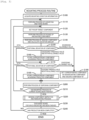
- FIG. 3 is a flowchart illustrating an example of a mounting process routine executed by CPU 41 of mounting control section 40 of mounting device 15.
- This routine is stored in memory section 42 of mounting device 15 and executed in accordance with a starting instruction from an operator.
- CPU 41 reads and acquires mounting condition information of board S to be produced this time (S100).
- CPU 41 reads mounting condition information 43 that is acquired from host PC 60 and stored in memory section 42.
- CPU 41 causes board processing section 22 to convey board S to a mounting position and to perform a process of fixing board S (S110).
- CPU 41 sets a component that is a pickup target based on mounting condition information 43 (S120), causes mounting head 32 to pick up component P from feeder 25 at a preset position and to move component P above pickup/imaging section 27 (S130).
- FIG. 4 is an explanatory diagram illustrating an example of mounting head 32 having picked up component P when viewed from the bottom.
- Fig. 4 illustrates an example in which mounting head 32 includes four nozzles 33.
- component P at the reference position is indicated by dotted lines.
- a positional deviation in the XY-coordinate directions occurs in component Pa with respect to the reference position, and a rotational deviation in which the component is rotated with respect to the reference position to cause an inclination occurs in component Pb.
- a picked-up state of component P may be changed.
- CPU 41 checks whether the positional deviation amount of component P is within a threshold value, exceeds the threshold value and within an allowable value, or exceeds the allowable value (S150).
- a predetermined threshold value at which a probability of a missing component or the like occurring when exceeding a positional deviation amount of component P in a picked-up state of component P is increased is empirically determined, and an allowable value that is larger than the threshold value and at which a normal product cannot be obtained even if component P is disposed on board S when exceeding the threshold value is also empirically determined.
- CPU 41 stores component P as a missing predicted component in board information 44 (S160). In this case, CPU 41 stores a disposition position number of corresponding component P in association with information as the misssing predicted component in board information 44 including identification information (ID) of board S After S160 or when the positional deviation amount of component P is within the threshold value in S150, CPU 41 checks whether the rotational deviation amount of component P is within the threshold value, exceeds the threshold value and within the allowable value, or exceeds the allowable value (S170).
- a predetermined threshold value at which a probability of a missing component or the like occurring when exceeding a rotational deviation amount in a picked-up state of component P is increased is empirically determined, and an allowable value that is larger than the threshold value and at which a normal product cannot be obtained even if component P is disposed on board S when exceeding the threshold value is also empirically determined.
- corresponding component P is stored in board information 44 as a missing predicted component (S180).
- CPU 41 stores a disposition position number of corresponding component P in association with information as the missing predicted component in board information 44 including identification information (ID) of board S.
- ID identification information
- the information obtained from an image captured by pickup/imaging section 27 and possibly leading to a defect thereafter is stored in board information 44. According to board information 44, it is possible to manage by which mounting device 15 component P mounted may be defective.
- CPU 41 determines that a board on which component P is to be mounted will be a defective board, sets corresponding component P as a non-mounting component not used for a mounting process, and then performs a process of discarding component P (S190).
- CPU 41 discards the non-mounting component in a predetermined discarding location after disposing normal components P on board S.
- Components P instead of discarded components P may be collectively mounted at the end of the mounting process of mounting device 15.
- CPU 41 After S190, after S180, or when the rotational deviation amount of component P is within the threshold value in S170, CPU 41 causes mounting section 30 to execute a process of disposing component P (S200). Subsequently, CPU 41 determines whether the mounting process for board S that is currently fixed to the mounting position has been finished (S210), and executes the processes in and after S120 when the mounting process has not been finished. That is, CPU 41 sets component P to be picked up and disposed next, causes mounting section 30 to pick up component P, stores missing predicted component information in board information 44 according to a state of component P, or executes a process of disposing component P on board S while discarding a non-mounting component (S120 to S200).
- CPU 41 executes a missing component inspection and remounting process (S220).
- the missing component inspection and remounting process which will be described later in detail, is a process of inspecting the presence or absence of a missing component on board S, and executing a remounting process for the corresponding component when a component is missing.
- CPU 41 causes board processing section 22 to discharge board S for which the mounting has been finished (S230), and determines whether or not production of all boards S set in mounting condition information 43 has been completed (S240).
- Supply section 24 of the present embodiment corresponds to a supply section
- mounting section 30 corresponds to a mounting section
- inspection/imaging section 34 corresponds to an inspection/imaging section
- mounting control section 40 corresponds to a control section
- feeder 25 and tray 26 correspond to a holding member
- nozzle 33 and the mechanical chuck correspond to a pickup member
- pickup/imaging section 27 corresponds to pickup/imaging section.
- an example of the inspection and mounting method of the present disclosure is also clarified by describing the operation of mounting device 15.
- CPU 41 causes loader 18 to move nozzle 33 for picking up this missing component P to mounting section 30.
- component P can be picked up, and thus production can be executed more reliably and efficiently.
- the mounting device of the present disclosure may include a pickup/imaging section that captures an image of the component in a state of being picked up by the mounting section, and the control section may execute the missing component inspection process by using the captured image of the component in a state of being picked up by the mounting section.
- the control section may execute the missing component inspection process by using the captured image of the component in a state of being picked up by the mounting section.
- the control section may control the inspection/imaging section to execute a foreign object inspection process for detecting a foreign object present on the mounting target when a component on the mounting target is missing.
- production can be executed more efficiently by executing the foreign object inspection process only when a component is missing.
- the control section may execute the foreign object inspection process on some or all of regions where components are mounted on the mounting target.
- production can be executed more efficiently by executing the foreign object inspection process only on a region related to component mounting.
- the control section may execute the foreign object inspection process on a region where a component is to be mounted in the subsequent mounting process, a disposition region where a component having a special shape is disposed, or a disposition region where an expensive component is disposed.
- the inspection and mounting method may employ the aspect of the mounting device described above, or may include a step of expressing the function of the mounting device described above.
- the mounting device, the mounting system, and the inspection and mounting method of the present disclosure can be used in electronic component mounting fields.
Landscapes
- Engineering & Computer Science (AREA)
- Manufacturing & Machinery (AREA)
- Microelectronics & Electronic Packaging (AREA)
- Operations Research (AREA)
- Supply And Installment Of Electrical Components (AREA)
Applications Claiming Priority (1)
| Application Number | Priority Date | Filing Date | Title |
|---|---|---|---|
| PCT/JP2019/028508 WO2021014505A1 (ja) | 2019-07-19 | 2019-07-19 | 実装装置、実装システム及び検査実装方法 |
Publications (3)
| Publication Number | Publication Date |
|---|---|
| EP4002977A1 EP4002977A1 (en) | 2022-05-25 |
| EP4002977A4 EP4002977A4 (en) | 2022-08-03 |
| EP4002977B1 true EP4002977B1 (en) | 2024-09-04 |
Family
ID=74193737
Family Applications (1)
| Application Number | Title | Priority Date | Filing Date |
|---|---|---|---|
| EP19938679.8A Active EP4002977B1 (en) | 2019-07-19 | 2019-07-19 | Mounting device, mounting system, and inspection and mounting method |
Country Status (5)
| Country | Link |
|---|---|
| US (1) | US12262476B2 (https=) |
| EP (1) | EP4002977B1 (https=) |
| JP (1) | JP7197705B2 (https=) |
| CN (1) | CN114041332B (https=) |
| WO (1) | WO2021014505A1 (https=) |
Families Citing this family (1)
| Publication number | Priority date | Publication date | Assignee | Title |
|---|---|---|---|---|
| CN113591589B (zh) * | 2021-07-02 | 2022-09-27 | 北京百度网讯科技有限公司 | 产品漏检的识别方法、装置、电子设备及存储介质 |
Family Cites Families (23)
| Publication number | Priority date | Publication date | Assignee | Title |
|---|---|---|---|---|
| JPH04324999A (ja) * | 1991-04-25 | 1992-11-13 | Matsushita Electric Ind Co Ltd | 電子部品の実装方法 |
| JP2000013097A (ja) * | 1998-06-18 | 2000-01-14 | Juki Corp | 部品搭載装置 |
| JP4045838B2 (ja) * | 2002-04-12 | 2008-02-13 | 松下電器産業株式会社 | 部品装着管理方法 |
| WO2004017704A1 (ja) * | 2002-08-06 | 2004-02-26 | Matsushita Electric Industrial Co., Ltd. | 部品実装方法、及び部品実装装置 |
| JP2006349441A (ja) * | 2005-06-15 | 2006-12-28 | Dainippon Printing Co Ltd | ワークの検査方法、およびワークの検査装置 |
| JP2007158052A (ja) * | 2005-12-06 | 2007-06-21 | Matsushita Electric Ind Co Ltd | 電子部品実装装置及び実装エラー修復方法 |
| JP2007214212A (ja) * | 2006-02-07 | 2007-08-23 | Matsushita Electric Ind Co Ltd | 実装状態判定方法、実装状態判定プログラム、実装状態判定装置、実装方法 |
| US20090000110A1 (en) * | 2006-02-27 | 2009-01-01 | Yasuhiro Maenishi | Mounting Method and Component Mounter |
| JP2009198397A (ja) * | 2008-02-22 | 2009-09-03 | Nagoya Electric Works Co Ltd | 基板検査装置および基板検査方法 |
| US20100155106A1 (en) * | 2008-12-22 | 2010-06-24 | Sun Microsystems, Inc. | Method and apparatus for optical differentiation to detect missing components on a circuit board |
| JP5201115B2 (ja) * | 2009-10-08 | 2013-06-05 | パナソニック株式会社 | 部品実装システム |
| JP5877639B2 (ja) * | 2010-12-27 | 2016-03-08 | 富士機械製造株式会社 | 画像生成装置および画像生成方法 |
| CN103597920B (zh) * | 2011-05-31 | 2016-06-29 | 富士机械制造株式会社 | 对基板作业支援装置及对基板作业支援方法 |
| JP2014007213A (ja) * | 2012-06-22 | 2014-01-16 | Panasonic Corp | 部品実装装置及び部品実装方法 |
| EP3048439B1 (en) * | 2013-09-17 | 2019-08-21 | FUJI Corporation | Mounting inspection device |
| CN103528523A (zh) * | 2013-11-06 | 2014-01-22 | 湖北工业大学 | 一种基于三维立体建模的螺纹检测方法及系统 |
| WO2016110941A1 (ja) * | 2015-01-06 | 2016-07-14 | 富士機械製造株式会社 | 実装関連処理装置、画像処理方法及びそのプログラム |
| JP6550589B2 (ja) * | 2015-02-24 | 2019-07-31 | パナソニックIpマネジメント株式会社 | 部品実装方法 |
| US10820459B2 (en) | 2015-08-25 | 2020-10-27 | Fuji Corporation | Component mounting line |
| JP6762968B2 (ja) | 2016-02-17 | 2020-09-30 | 株式会社Fuji | 作業装置および生産ライン |
| WO2017216950A1 (ja) * | 2016-06-17 | 2017-12-21 | 富士機械製造株式会社 | 部品実装装置及び部品実装システム |
| JP6837138B2 (ja) * | 2017-05-01 | 2021-03-03 | 株式会社Fuji | 実装装置、情報処理装置、実装システム、実装方法及び情報処理方法 |
| JP7084416B2 (ja) * | 2017-12-15 | 2022-06-14 | 株式会社Fuji | 情報処理装置及び情報処理方法 |
-
2019
- 2019-07-19 JP JP2021534864A patent/JP7197705B2/ja active Active
- 2019-07-19 WO PCT/JP2019/028508 patent/WO2021014505A1/ja not_active Ceased
- 2019-07-19 US US17/628,087 patent/US12262476B2/en active Active
- 2019-07-19 CN CN201980098038.8A patent/CN114041332B/zh active Active
- 2019-07-19 EP EP19938679.8A patent/EP4002977B1/en active Active
Also Published As
| Publication number | Publication date |
|---|---|
| CN114041332A (zh) | 2022-02-11 |
| EP4002977A1 (en) | 2022-05-25 |
| US20220322595A1 (en) | 2022-10-06 |
| WO2021014505A1 (ja) | 2021-01-28 |
| EP4002977A4 (en) | 2022-08-03 |
| JPWO2021014505A1 (https=) | 2021-01-28 |
| JP7197705B2 (ja) | 2022-12-27 |
| US12262476B2 (en) | 2025-03-25 |
| CN114041332B (zh) | 2024-01-30 |
Similar Documents
| Publication | Publication Date | Title |
|---|---|---|
| JP7314216B2 (ja) | フィーダの取り外し及び取り付け方法 | |
| US12550309B2 (en) | Component mounting system | |
| JP2003304100A (ja) | 部品装着管理方法、装着検査装置および装着システム | |
| EP3346816B1 (en) | Component-mounting machine | |
| CN114930160B (zh) | 检查装置以及检查方法 | |
| EP4002977B1 (en) | Mounting device, mounting system, and inspection and mounting method | |
| EP4009759B1 (en) | Mounting device, mounting system, and inspection/mounting method | |
| US20230371224A1 (en) | Management device, management method, and work device | |
| JPWO2016139753A1 (ja) | 部品実装機 | |
| US12302503B2 (en) | Component mounting system | |
| US12160958B2 (en) | Mounting device and method for controlling mounting device | |
| US20230413501A1 (en) | Management device and management method, and work device | |
| CN115700028A (zh) | 元件安装系统 | |
| JP7752354B2 (ja) | 部品装着装置および部品装着方法 | |
| JP7761676B2 (ja) | 準備装置、実装装置、実装システム及び情報処理方法 | |
| JP7249490B2 (ja) | 部品実装装置 | |
| CN114026975B (zh) | 元件安装机 | |
| JP2024062605A (ja) | 制御装置、検査方法、および対基板作業機 | |
| JP2026007777A (ja) | 異物検出装置および異物検出方法 | |
| JP6760790B2 (ja) | 表面実装機 | |
| JP2023060597A (ja) | 部品実装システム | |
| JP2021132160A (ja) | 部品実装システムおよび方法 | |
| EP3373717A1 (en) | Component mounting system and component mounting device | |
| WO2018146766A1 (ja) | 実装機およびエラー報知方法 |
Legal Events
| Date | Code | Title | Description |
|---|---|---|---|
| STAA | Information on the status of an ep patent application or granted ep patent |
Free format text: STATUS: THE INTERNATIONAL PUBLICATION HAS BEEN MADE |
|
| PUAI | Public reference made under article 153(3) epc to a published international application that has entered the european phase |
Free format text: ORIGINAL CODE: 0009012 |
|
| STAA | Information on the status of an ep patent application or granted ep patent |
Free format text: STATUS: REQUEST FOR EXAMINATION WAS MADE |
|
| 17P | Request for examination filed |
Effective date: 20211228 |
|
| AK | Designated contracting states |
Kind code of ref document: A1 Designated state(s): AL AT BE BG CH CY CZ DE DK EE ES FI FR GB GR HR HU IE IS IT LI LT LU LV MC MK MT NL NO PL PT RO RS SE SI SK SM TR |
|
| A4 | Supplementary search report drawn up and despatched |
Effective date: 20220630 |
|
| RIC1 | Information provided on ipc code assigned before grant |
Ipc: H05K 13/08 20060101AFI20220624BHEP |
|
| DAV | Request for validation of the european patent (deleted) | ||
| DAX | Request for extension of the european patent (deleted) | ||
| P01 | Opt-out of the competence of the unified patent court (upc) registered |
Effective date: 20230328 |
|
| GRAP | Despatch of communication of intention to grant a patent |
Free format text: ORIGINAL CODE: EPIDOSNIGR1 |
|
| STAA | Information on the status of an ep patent application or granted ep patent |
Free format text: STATUS: GRANT OF PATENT IS INTENDED |
|
| INTG | Intention to grant announced |
Effective date: 20240605 |
|
| GRAS | Grant fee paid |
Free format text: ORIGINAL CODE: EPIDOSNIGR3 |
|
| GRAA | (expected) grant |
Free format text: ORIGINAL CODE: 0009210 |
|
| STAA | Information on the status of an ep patent application or granted ep patent |
Free format text: STATUS: THE PATENT HAS BEEN GRANTED |
|
| AK | Designated contracting states |
Kind code of ref document: B1 Designated state(s): AL AT BE BG CH CY CZ DE DK EE ES FI FR GB GR HR HU IE IS IT LI LT LU LV MC MK MT NL NO PL PT RO RS SE SI SK SM TR |
|
| REG | Reference to a national code |
Ref country code: GB Ref legal event code: FG4D |
|
| REG | Reference to a national code |
Ref country code: CH Ref legal event code: EP |
|
| REG | Reference to a national code |
Ref country code: IE Ref legal event code: FG4D |
|
| REG | Reference to a national code |
Ref country code: DE Ref legal event code: R096 Ref document number: 602019058548 Country of ref document: DE |
|
| REG | Reference to a national code |
Ref country code: LT Ref legal event code: MG9D |
|
| REG | Reference to a national code |
Ref country code: NL Ref legal event code: MP Effective date: 20240904 |
|
| PG25 | Lapsed in a contracting state [announced via postgrant information from national office to epo] |
Ref country code: NO Free format text: LAPSE BECAUSE OF FAILURE TO SUBMIT A TRANSLATION OF THE DESCRIPTION OR TO PAY THE FEE WITHIN THE PRESCRIBED TIME-LIMIT Effective date: 20241204 |
|
| PG25 | Lapsed in a contracting state [announced via postgrant information from national office to epo] |
Ref country code: PL Free format text: LAPSE BECAUSE OF FAILURE TO SUBMIT A TRANSLATION OF THE DESCRIPTION OR TO PAY THE FEE WITHIN THE PRESCRIBED TIME-LIMIT Effective date: 20240904 Ref country code: GR Free format text: LAPSE BECAUSE OF FAILURE TO SUBMIT A TRANSLATION OF THE DESCRIPTION OR TO PAY THE FEE WITHIN THE PRESCRIBED TIME-LIMIT Effective date: 20241205 Ref country code: FI Free format text: LAPSE BECAUSE OF FAILURE TO SUBMIT A TRANSLATION OF THE DESCRIPTION OR TO PAY THE FEE WITHIN THE PRESCRIBED TIME-LIMIT Effective date: 20240904 |
|
| PG25 | Lapsed in a contracting state [announced via postgrant information from national office to epo] |
Ref country code: BG Free format text: LAPSE BECAUSE OF FAILURE TO SUBMIT A TRANSLATION OF THE DESCRIPTION OR TO PAY THE FEE WITHIN THE PRESCRIBED TIME-LIMIT Effective date: 20240904 |
|
| PG25 | Lapsed in a contracting state [announced via postgrant information from national office to epo] |
Ref country code: LV Free format text: LAPSE BECAUSE OF FAILURE TO SUBMIT A TRANSLATION OF THE DESCRIPTION OR TO PAY THE FEE WITHIN THE PRESCRIBED TIME-LIMIT Effective date: 20240904 |
|
| PG25 | Lapsed in a contracting state [announced via postgrant information from national office to epo] |
Ref country code: HR Free format text: LAPSE BECAUSE OF FAILURE TO SUBMIT A TRANSLATION OF THE DESCRIPTION OR TO PAY THE FEE WITHIN THE PRESCRIBED TIME-LIMIT Effective date: 20240904 |
|
| PG25 | Lapsed in a contracting state [announced via postgrant information from national office to epo] |
Ref country code: RS Free format text: LAPSE BECAUSE OF FAILURE TO SUBMIT A TRANSLATION OF THE DESCRIPTION OR TO PAY THE FEE WITHIN THE PRESCRIBED TIME-LIMIT Effective date: 20241204 Ref country code: ES Free format text: LAPSE BECAUSE OF FAILURE TO SUBMIT A TRANSLATION OF THE DESCRIPTION OR TO PAY THE FEE WITHIN THE PRESCRIBED TIME-LIMIT Effective date: 20240904 |
|
| PG25 | Lapsed in a contracting state [announced via postgrant information from national office to epo] |
Ref country code: RS Free format text: LAPSE BECAUSE OF FAILURE TO SUBMIT A TRANSLATION OF THE DESCRIPTION OR TO PAY THE FEE WITHIN THE PRESCRIBED TIME-LIMIT Effective date: 20241204 Ref country code: PL Free format text: LAPSE BECAUSE OF FAILURE TO SUBMIT A TRANSLATION OF THE DESCRIPTION OR TO PAY THE FEE WITHIN THE PRESCRIBED TIME-LIMIT Effective date: 20240904 Ref country code: NO Free format text: LAPSE BECAUSE OF FAILURE TO SUBMIT A TRANSLATION OF THE DESCRIPTION OR TO PAY THE FEE WITHIN THE PRESCRIBED TIME-LIMIT Effective date: 20241204 Ref country code: LV Free format text: LAPSE BECAUSE OF FAILURE TO SUBMIT A TRANSLATION OF THE DESCRIPTION OR TO PAY THE FEE WITHIN THE PRESCRIBED TIME-LIMIT Effective date: 20240904 Ref country code: HR Free format text: LAPSE BECAUSE OF FAILURE TO SUBMIT A TRANSLATION OF THE DESCRIPTION OR TO PAY THE FEE WITHIN THE PRESCRIBED TIME-LIMIT Effective date: 20240904 Ref country code: GR Free format text: LAPSE BECAUSE OF FAILURE TO SUBMIT A TRANSLATION OF THE DESCRIPTION OR TO PAY THE FEE WITHIN THE PRESCRIBED TIME-LIMIT Effective date: 20241205 Ref country code: FI Free format text: LAPSE BECAUSE OF FAILURE TO SUBMIT A TRANSLATION OF THE DESCRIPTION OR TO PAY THE FEE WITHIN THE PRESCRIBED TIME-LIMIT Effective date: 20240904 Ref country code: ES Free format text: LAPSE BECAUSE OF FAILURE TO SUBMIT A TRANSLATION OF THE DESCRIPTION OR TO PAY THE FEE WITHIN THE PRESCRIBED TIME-LIMIT Effective date: 20240904 Ref country code: BG Free format text: LAPSE BECAUSE OF FAILURE TO SUBMIT A TRANSLATION OF THE DESCRIPTION OR TO PAY THE FEE WITHIN THE PRESCRIBED TIME-LIMIT Effective date: 20240904 |
|
| REG | Reference to a national code |
Ref country code: AT Ref legal event code: MK05 Ref document number: 1721781 Country of ref document: AT Kind code of ref document: T Effective date: 20240904 |
|
| PG25 | Lapsed in a contracting state [announced via postgrant information from national office to epo] |
Ref country code: NL Free format text: LAPSE BECAUSE OF FAILURE TO SUBMIT A TRANSLATION OF THE DESCRIPTION OR TO PAY THE FEE WITHIN THE PRESCRIBED TIME-LIMIT Effective date: 20240904 |
|
| PG25 | Lapsed in a contracting state [announced via postgrant information from national office to epo] |
Ref country code: PT Free format text: LAPSE BECAUSE OF FAILURE TO SUBMIT A TRANSLATION OF THE DESCRIPTION OR TO PAY THE FEE WITHIN THE PRESCRIBED TIME-LIMIT Effective date: 20250106 Ref country code: IS Free format text: LAPSE BECAUSE OF FAILURE TO SUBMIT A TRANSLATION OF THE DESCRIPTION OR TO PAY THE FEE WITHIN THE PRESCRIBED TIME-LIMIT Effective date: 20250104 |
|
| PG25 | Lapsed in a contracting state [announced via postgrant information from national office to epo] |
Ref country code: RO Free format text: LAPSE BECAUSE OF FAILURE TO SUBMIT A TRANSLATION OF THE DESCRIPTION OR TO PAY THE FEE WITHIN THE PRESCRIBED TIME-LIMIT Effective date: 20240904 Ref country code: SM Free format text: LAPSE BECAUSE OF FAILURE TO SUBMIT A TRANSLATION OF THE DESCRIPTION OR TO PAY THE FEE WITHIN THE PRESCRIBED TIME-LIMIT Effective date: 20240904 |
|
| PG25 | Lapsed in a contracting state [announced via postgrant information from national office to epo] |
Ref country code: EE Free format text: LAPSE BECAUSE OF FAILURE TO SUBMIT A TRANSLATION OF THE DESCRIPTION OR TO PAY THE FEE WITHIN THE PRESCRIBED TIME-LIMIT Effective date: 20240904 Ref country code: AT Free format text: LAPSE BECAUSE OF FAILURE TO SUBMIT A TRANSLATION OF THE DESCRIPTION OR TO PAY THE FEE WITHIN THE PRESCRIBED TIME-LIMIT Effective date: 20240904 |
|
| PG25 | Lapsed in a contracting state [announced via postgrant information from national office to epo] |
Ref country code: CZ Free format text: LAPSE BECAUSE OF FAILURE TO SUBMIT A TRANSLATION OF THE DESCRIPTION OR TO PAY THE FEE WITHIN THE PRESCRIBED TIME-LIMIT Effective date: 20240904 |
|
| PG25 | Lapsed in a contracting state [announced via postgrant information from national office to epo] |
Ref country code: IT Free format text: LAPSE BECAUSE OF FAILURE TO SUBMIT A TRANSLATION OF THE DESCRIPTION OR TO PAY THE FEE WITHIN THE PRESCRIBED TIME-LIMIT Effective date: 20240904 Ref country code: SK Free format text: LAPSE BECAUSE OF FAILURE TO SUBMIT A TRANSLATION OF THE DESCRIPTION OR TO PAY THE FEE WITHIN THE PRESCRIBED TIME-LIMIT Effective date: 20240904 |
|
| REG | Reference to a national code |
Ref country code: DE Ref legal event code: R097 Ref document number: 602019058548 Country of ref document: DE |
|
| PG25 | Lapsed in a contracting state [announced via postgrant information from national office to epo] |
Ref country code: DK Free format text: LAPSE BECAUSE OF FAILURE TO SUBMIT A TRANSLATION OF THE DESCRIPTION OR TO PAY THE FEE WITHIN THE PRESCRIBED TIME-LIMIT Effective date: 20240904 |
|
| PLBE | No opposition filed within time limit |
Free format text: ORIGINAL CODE: 0009261 |
|
| STAA | Information on the status of an ep patent application or granted ep patent |
Free format text: STATUS: NO OPPOSITION FILED WITHIN TIME LIMIT |
|
| 26N | No opposition filed |
Effective date: 20250605 |
|
| PG25 | Lapsed in a contracting state [announced via postgrant information from national office to epo] |
Ref country code: SE Free format text: LAPSE BECAUSE OF FAILURE TO SUBMIT A TRANSLATION OF THE DESCRIPTION OR TO PAY THE FEE WITHIN THE PRESCRIBED TIME-LIMIT Effective date: 20240904 |
|
| PGFP | Annual fee paid to national office [announced via postgrant information from national office to epo] |
Ref country code: DE Payment date: 20250528 Year of fee payment: 7 |
|
| REG | Reference to a national code |
Ref country code: CH Ref legal event code: H13 Free format text: ST27 STATUS EVENT CODE: U-0-0-H10-H13 (AS PROVIDED BY THE NATIONAL OFFICE) Effective date: 20260224 |
|
| PG25 | Lapsed in a contracting state [announced via postgrant information from national office to epo] |
Ref country code: LU Free format text: LAPSE BECAUSE OF NON-PAYMENT OF DUE FEES Effective date: 20250719 |
|
| GBPC | Gb: european patent ceased through non-payment of renewal fee |
Effective date: 20250719 |
|
| REG | Reference to a national code |
Ref country code: BE Ref legal event code: MM Effective date: 20250731 |
|
| PG25 | Lapsed in a contracting state [announced via postgrant information from national office to epo] |
Ref country code: GB Free format text: LAPSE BECAUSE OF NON-PAYMENT OF DUE FEES Effective date: 20250719 |
|
| PG25 | Lapsed in a contracting state [announced via postgrant information from national office to epo] |
Ref country code: BE Free format text: LAPSE BECAUSE OF NON-PAYMENT OF DUE FEES Effective date: 20250731 |
|
| PG25 | Lapsed in a contracting state [announced via postgrant information from national office to epo] |
Ref country code: FR Free format text: LAPSE BECAUSE OF NON-PAYMENT OF DUE FEES Effective date: 20250731 |
|
| PG25 | Lapsed in a contracting state [announced via postgrant information from national office to epo] |
Ref country code: CH Free format text: LAPSE BECAUSE OF NON-PAYMENT OF DUE FEES Effective date: 20250731 |