EP4002323A1 - Verfahren und vorrichtung zur frühwarnung für ein vorhandenes fahrzeug - Google Patents
Verfahren und vorrichtung zur frühwarnung für ein vorhandenes fahrzeug Download PDFInfo
- Publication number
- EP4002323A1 EP4002323A1 EP20856199.3A EP20856199A EP4002323A1 EP 4002323 A1 EP4002323 A1 EP 4002323A1 EP 20856199 A EP20856199 A EP 20856199A EP 4002323 A1 EP4002323 A1 EP 4002323A1
- Authority
- EP
- European Patent Office
- Prior art keywords
- vehicle
- ego
- nearby
- remote
- driver
- Prior art date
- Legal status (The legal status is an assumption and is not a legal conclusion. Google has not performed a legal analysis and makes no representation as to the accuracy of the status listed.)
- Pending
Links
- 238000000034 method Methods 0.000 title claims abstract description 68
- 238000004422 calculation algorithm Methods 0.000 claims description 35
- 230000015654 memory Effects 0.000 claims description 25
- 230000004044 response Effects 0.000 claims description 24
- 238000013461 design Methods 0.000 description 50
- 238000004891 communication Methods 0.000 description 24
- 238000012545 processing Methods 0.000 description 23
- 230000006870 function Effects 0.000 description 20
- 238000010586 diagram Methods 0.000 description 12
- 238000007635 classification algorithm Methods 0.000 description 8
- 230000000694 effects Effects 0.000 description 7
- 230000002265 prevention Effects 0.000 description 5
- 238000004364 calculation method Methods 0.000 description 4
- 230000008859 change Effects 0.000 description 4
- 238000005516 engineering process Methods 0.000 description 4
- 230000008878 coupling Effects 0.000 description 3
- 238000010168 coupling process Methods 0.000 description 3
- 238000005859 coupling reaction Methods 0.000 description 3
- 238000001914 filtration Methods 0.000 description 3
- 238000007726 management method Methods 0.000 description 3
- 230000008569 process Effects 0.000 description 3
- 230000003321 amplification Effects 0.000 description 2
- 238000013528 artificial neural network Methods 0.000 description 2
- 230000003416 augmentation Effects 0.000 description 2
- 239000003086 colorant Substances 0.000 description 2
- 238000004590 computer program Methods 0.000 description 2
- 238000013500 data storage Methods 0.000 description 2
- 230000007423 decrease Effects 0.000 description 2
- 230000003993 interaction Effects 0.000 description 2
- 230000007774 longterm Effects 0.000 description 2
- 238000003199 nucleic acid amplification method Methods 0.000 description 2
- 238000012216 screening Methods 0.000 description 2
- 101001093748 Homo sapiens Phosphatidylinositol N-acetylglucosaminyltransferase subunit P Proteins 0.000 description 1
- 230000002411 adverse Effects 0.000 description 1
- 208000001491 myopia Diseases 0.000 description 1
- 230000003287 optical effect Effects 0.000 description 1
- 230000008054 signal transmission Effects 0.000 description 1
Images


Classifications
-
- B—PERFORMING OPERATIONS; TRANSPORTING
- B60—VEHICLES IN GENERAL
- B60Q—ARRANGEMENT OF SIGNALLING OR LIGHTING DEVICES, THE MOUNTING OR SUPPORTING THEREOF OR CIRCUITS THEREFOR, FOR VEHICLES IN GENERAL
- B60Q9/00—Arrangement or adaptation of signal devices not provided for in one of main groups B60Q1/00 - B60Q7/00, e.g. haptic signalling
- B60Q9/008—Arrangement or adaptation of signal devices not provided for in one of main groups B60Q1/00 - B60Q7/00, e.g. haptic signalling for anti-collision purposes
-
- B—PERFORMING OPERATIONS; TRANSPORTING
- B60—VEHICLES IN GENERAL
- B60W—CONJOINT CONTROL OF VEHICLE SUB-UNITS OF DIFFERENT TYPE OR DIFFERENT FUNCTION; CONTROL SYSTEMS SPECIALLY ADAPTED FOR HYBRID VEHICLES; ROAD VEHICLE DRIVE CONTROL SYSTEMS FOR PURPOSES NOT RELATED TO THE CONTROL OF A PARTICULAR SUB-UNIT
- B60W30/00—Purposes of road vehicle drive control systems not related to the control of a particular sub-unit, e.g. of systems using conjoint control of vehicle sub-units
- B60W30/08—Active safety systems predicting or avoiding probable or impending collision or attempting to minimise its consequences
- B60W30/095—Predicting travel path or likelihood of collision
- B60W30/0956—Predicting travel path or likelihood of collision the prediction being responsive to traffic or environmental parameters
-
- B—PERFORMING OPERATIONS; TRANSPORTING
- B60—VEHICLES IN GENERAL
- B60W—CONJOINT CONTROL OF VEHICLE SUB-UNITS OF DIFFERENT TYPE OR DIFFERENT FUNCTION; CONTROL SYSTEMS SPECIALLY ADAPTED FOR HYBRID VEHICLES; ROAD VEHICLE DRIVE CONTROL SYSTEMS FOR PURPOSES NOT RELATED TO THE CONTROL OF A PARTICULAR SUB-UNIT
- B60W40/00—Estimation or calculation of non-directly measurable driving parameters for road vehicle drive control systems not related to the control of a particular sub unit, e.g. by using mathematical models
- B60W40/10—Estimation or calculation of non-directly measurable driving parameters for road vehicle drive control systems not related to the control of a particular sub unit, e.g. by using mathematical models related to vehicle motion
- B60W40/114—Yaw movement
-
- B—PERFORMING OPERATIONS; TRANSPORTING
- B60—VEHICLES IN GENERAL
- B60W—CONJOINT CONTROL OF VEHICLE SUB-UNITS OF DIFFERENT TYPE OR DIFFERENT FUNCTION; CONTROL SYSTEMS SPECIALLY ADAPTED FOR HYBRID VEHICLES; ROAD VEHICLE DRIVE CONTROL SYSTEMS FOR PURPOSES NOT RELATED TO THE CONTROL OF A PARTICULAR SUB-UNIT
- B60W50/00—Details of control systems for road vehicle drive control not related to the control of a particular sub-unit, e.g. process diagnostic or vehicle driver interfaces
- B60W50/08—Interaction between the driver and the control system
- B60W50/14—Means for informing the driver, warning the driver or prompting a driver intervention
-
- G—PHYSICS
- G01—MEASURING; TESTING
- G01S—RADIO DIRECTION-FINDING; RADIO NAVIGATION; DETERMINING DISTANCE OR VELOCITY BY USE OF RADIO WAVES; LOCATING OR PRESENCE-DETECTING BY USE OF THE REFLECTION OR RERADIATION OF RADIO WAVES; ANALOGOUS ARRANGEMENTS USING OTHER WAVES
- G01S13/00—Systems using the reflection or reradiation of radio waves, e.g. radar systems; Analogous systems using reflection or reradiation of waves whose nature or wavelength is irrelevant or unspecified
- G01S13/88—Radar or analogous systems specially adapted for specific applications
- G01S13/93—Radar or analogous systems specially adapted for specific applications for anti-collision purposes
- G01S13/931—Radar or analogous systems specially adapted for specific applications for anti-collision purposes of land vehicles
-
- G—PHYSICS
- G01—MEASURING; TESTING
- G01S—RADIO DIRECTION-FINDING; RADIO NAVIGATION; DETERMINING DISTANCE OR VELOCITY BY USE OF RADIO WAVES; LOCATING OR PRESENCE-DETECTING BY USE OF THE REFLECTION OR RERADIATION OF RADIO WAVES; ANALOGOUS ARRANGEMENTS USING OTHER WAVES
- G01S17/00—Systems using the reflection or reradiation of electromagnetic waves other than radio waves, e.g. lidar systems
- G01S17/88—Lidar systems specially adapted for specific applications
- G01S17/93—Lidar systems specially adapted for specific applications for anti-collision purposes
- G01S17/931—Lidar systems specially adapted for specific applications for anti-collision purposes of land vehicles
-
- G—PHYSICS
- G08—SIGNALLING
- G08G—TRAFFIC CONTROL SYSTEMS
- G08G1/00—Traffic control systems for road vehicles
- G08G1/16—Anti-collision systems
- G08G1/161—Decentralised systems, e.g. inter-vehicle communication
- G08G1/163—Decentralised systems, e.g. inter-vehicle communication involving continuous checking
-
- G—PHYSICS
- G08—SIGNALLING
- G08G—TRAFFIC CONTROL SYSTEMS
- G08G1/00—Traffic control systems for road vehicles
- G08G1/16—Anti-collision systems
- G08G1/166—Anti-collision systems for active traffic, e.g. moving vehicles, pedestrians, bikes
-
- B—PERFORMING OPERATIONS; TRANSPORTING
- B60—VEHICLES IN GENERAL
- B60W—CONJOINT CONTROL OF VEHICLE SUB-UNITS OF DIFFERENT TYPE OR DIFFERENT FUNCTION; CONTROL SYSTEMS SPECIALLY ADAPTED FOR HYBRID VEHICLES; ROAD VEHICLE DRIVE CONTROL SYSTEMS FOR PURPOSES NOT RELATED TO THE CONTROL OF A PARTICULAR SUB-UNIT
- B60W50/00—Details of control systems for road vehicle drive control not related to the control of a particular sub-unit, e.g. process diagnostic or vehicle driver interfaces
- B60W50/08—Interaction between the driver and the control system
- B60W50/14—Means for informing the driver, warning the driver or prompting a driver intervention
- B60W2050/146—Display means
-
- B—PERFORMING OPERATIONS; TRANSPORTING
- B60—VEHICLES IN GENERAL
- B60W—CONJOINT CONTROL OF VEHICLE SUB-UNITS OF DIFFERENT TYPE OR DIFFERENT FUNCTION; CONTROL SYSTEMS SPECIALLY ADAPTED FOR HYBRID VEHICLES; ROAD VEHICLE DRIVE CONTROL SYSTEMS FOR PURPOSES NOT RELATED TO THE CONTROL OF A PARTICULAR SUB-UNIT
- B60W2554/00—Input parameters relating to objects
- B60W2554/80—Spatial relation or speed relative to objects
-
- B—PERFORMING OPERATIONS; TRANSPORTING
- B60—VEHICLES IN GENERAL
- B60W—CONJOINT CONTROL OF VEHICLE SUB-UNITS OF DIFFERENT TYPE OR DIFFERENT FUNCTION; CONTROL SYSTEMS SPECIALLY ADAPTED FOR HYBRID VEHICLES; ROAD VEHICLE DRIVE CONTROL SYSTEMS FOR PURPOSES NOT RELATED TO THE CONTROL OF A PARTICULAR SUB-UNIT
- B60W2556/00—Input parameters relating to data
- B60W2556/45—External transmission of data to or from the vehicle
-
- G—PHYSICS
- G01—MEASURING; TESTING
- G01S—RADIO DIRECTION-FINDING; RADIO NAVIGATION; DETERMINING DISTANCE OR VELOCITY BY USE OF RADIO WAVES; LOCATING OR PRESENCE-DETECTING BY USE OF THE REFLECTION OR RERADIATION OF RADIO WAVES; ANALOGOUS ARRANGEMENTS USING OTHER WAVES
- G01S13/00—Systems using the reflection or reradiation of radio waves, e.g. radar systems; Analogous systems using reflection or reradiation of waves whose nature or wavelength is irrelevant or unspecified
- G01S13/88—Radar or analogous systems specially adapted for specific applications
- G01S13/93—Radar or analogous systems specially adapted for specific applications for anti-collision purposes
- G01S13/931—Radar or analogous systems specially adapted for specific applications for anti-collision purposes of land vehicles
- G01S2013/9316—Radar or analogous systems specially adapted for specific applications for anti-collision purposes of land vehicles combined with communication equipment with other vehicles or with base stations
-
- G—PHYSICS
- G01—MEASURING; TESTING
- G01S—RADIO DIRECTION-FINDING; RADIO NAVIGATION; DETERMINING DISTANCE OR VELOCITY BY USE OF RADIO WAVES; LOCATING OR PRESENCE-DETECTING BY USE OF THE REFLECTION OR RERADIATION OF RADIO WAVES; ANALOGOUS ARRANGEMENTS USING OTHER WAVES
- G01S13/00—Systems using the reflection or reradiation of radio waves, e.g. radar systems; Analogous systems using reflection or reradiation of waves whose nature or wavelength is irrelevant or unspecified
- G01S13/88—Radar or analogous systems specially adapted for specific applications
- G01S13/93—Radar or analogous systems specially adapted for specific applications for anti-collision purposes
- G01S13/931—Radar or analogous systems specially adapted for specific applications for anti-collision purposes of land vehicles
- G01S2013/932—Radar or analogous systems specially adapted for specific applications for anti-collision purposes of land vehicles using own vehicle data, e.g. ground speed, steering wheel direction
Definitions
- Embodiments of this application relate to the intelligent transportation field, and in particular, to an ego-vehicle warning method and apparatus.
- a vehicle collision warning such as a forward vehicle collision warning, a crossroad collision warning, a lane change warning, a reverse overtaking warning, a left turn assisted warning, or a blind zone warning
- V2V vehicle to vehicle
- a method for warning an ego-vehicle moving on a road against a vehicle collision risk is as follows: The ego-vehicle obtains moving status data of the ego-vehicle, then obtains information such as a position, a moving speed, and a direction of a surrounding vehicle or a surrounding obstacle of the ego-vehicle with reference to a motion sensor of the ego-vehicle (such as a laser radar, a 360° panoramic camera, or a millimeter wave radar), then determines, according to a moving path prediction calculation method, whether the ego-vehicle will collide with the surrounding obstacle or the surrounding vehicle in a future time period, and when the ego-vehicle collides with the surrounding obstacle or the surrounding vehicle in the future time period, sends alarm information to a driver of the ego-vehicle, so that the driver adjusts a driving status of the ego-vehi
- the existing vehicle warning method includes some disadvantages.
- the existing vehicle warning method mainly focuses on a discussion of the ego-vehicle and the surrounding vehicle or the surrounding obstacle, that is, focuses only on a collision risk between the ego-vehicle and things surrounding the ego-vehicle, and simply calculates whether the surrounding vehicle directly poses a collision threat to the ego-vehicle, but does not calculate adverse impact of a collision between other surrounding vehicles on the ego-vehicle.
- the method is subject to a "short-sighted" trap.
- Embodiments of this application provide an ego-vehicle warning method and apparatus, to resolve a problem that a safety warning capability of an ego-vehicle is relatively low when an accidental collision accident not caused by the ego-vehicle or another accident occurs between vehicles surrounding the ego-vehicle.
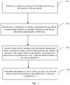
- this application provides an ego-vehicle warning method, where the method includes: determining a nearby area of an ego-vehicle based on moving information of the ego-vehicle; performing target classification on vehicles surrounding the ego-vehicle to obtain a nearby vehicle closest to the ego-vehicle in a plurality of directions and relative to the ego-vehicle and a remote vehicle set including at least one remote vehicle in the plurality of directions; for any remote vehicle in the remote vehicle set, calculating a shortest distance between the remote vehicle and a nearby vehicle in each direction that matches a direction of the remote vehicle in the plurality of directions in a future time period, and recording a time T when the shortest distance is less than a threshold D; and using a nearby vehicle corresponding to an earliest time T among all recorded times T as a warning vehicle, and sending alarm information to a driver of the ego-vehicle, where the alarm information is used to indicate to the driver that an accidental collision accident not caused by
- nearby vehicles surrounding the ego-vehicle and associated with the ego-vehicle and a remote vehicle set including at least one remote vehicle may be determined based on the nearby area of the ego-vehicle, a time T at which each remote vehicle may collide with a nearby vehicle in a direction matching that of the remote vehicle is predicted, a nearby vehicle corresponding to an earliest time T is used as a most threatening vehicle for the ego-vehicle, and the driver is prompted that a collision risk may occur in the direction of the nearby vehicle.
- the moving information of the ego-vehicle includes a current moving speed v of the ego-vehicle, a heading of the ego-vehicle, and a yawing rate of the ego-vehicle; and the determining a nearby area of an ego-vehicle based on moving information of the ego-vehicle includes: determining the nearby area of the ego-vehicle based on a deceleration a of the ego-vehicle, a response time ⁇ t of the driver, a safety distance A, the current moving speed v of the ego-vehicle, the heading of the ego-vehicle, and the yawing rate of the ego-vehicle.
- the nearby area of the ego-vehicle can be determined based on a plurality of objective factors such as the response time of the driver, the current vehicle speed, and the deceleration in vehicle braking, so that the nearby area and a non-nearby area of the ego-vehicle are classified more properly. This ensures that after a collision risk between a vehicle in the nearby area of the ego-vehicle and another vehicle is detected, the driver has a sufficient time to respond while considering a braking time to avoid the risk.
- the deceleration a of the ego-vehicle, the response time ⁇ t of the driver, and the safety distance A are preset based on experience or adjusted by a user based on a requirement.
- a parameter for determining the nearby area of the ego-vehicle may be set at discretion based on the individual response time of the driver and a deceleration time in vehicle braking. In this way, the user can perform an adjustment based on an appropriate driving level of the user, to obtain a more accurate warning prompt effect that is more suitable for the user and improve user experience.
- the performing target classification on vehicles surrounding the ego-vehicle to obtain nearby vehicles in a plurality of directions and remote vehicle sets in the plurality of directions includes: obtaining moving information of the vehicles surrounding the ego-vehicle; determining, based on the moving information of the vehicles surrounding the ego-vehicle and a vehicle kinematics algorithm, vehicle sets that are in the plurality of directions and associated with the ego-vehicle among the vehicles surrounding the ego-vehicle; and determining a vehicle that is in the vehicle set and is located in the nearby area of the ego-vehicle and closest to the ego-vehicle as a nearby vehicle, and determining a vehicle that is in the vehicle set and is located outside the nearby area as a remote vehicle in the remote vehicle set.
- the vehicle kinematics algorithm may be a target classification algorithm. Based on the possible design, the vehicle kinematics algorithm can be used to classify the vehicles surrounding the ego-vehicle into two types: nearby vehicles and remote vehicles. This is simple and feasible.
- calculating a shortest distance between the nearby vehicle in the direction and the remote vehicle in a future time period includes: obtaining an analytic path prediction expression of the nearby vehicle based on a path collision prediction algorithm and moving information of the nearby vehicle, where the analytic path prediction expression of the nearby vehicle is a relation between a time and a moving position of the nearby vehicle; obtaining an analytic path prediction expression of the remote vehicle based on the path collision prediction algorithm and moving information of the remote vehicle, where the analytic path prediction expression of the remote vehicle is a relation between a time and a moving position of the remote vehicle; and calculating the shortest distance between the nearby vehicle and the remote vehicle in the future time period based on the analytic path prediction expression of the nearby vehicle and the analytic path prediction expression of the nearby vehicle.
- each remote vehicle can be traversed based on the path collision prediction algorithm, and the shortest distance between the remote vehicle and the nearby vehicle in the direction matching that of the remote vehicle in the future time period can be calculated. This is simple and feasible.
- the sending alarm information to a driver of the ego-vehicle includes: sending the alarm information to the driver of the ego-vehicle by using an audio electronic control unit ECU; or sending the alarm information to the driver of the ego-vehicle by using an indicator or by using an audio ECU and a user interface UI.
- the alarm information is sent to the driver in a form of sound or by turning on/off the indicator or by using a combination of audio displaying and user interface displaying. This is easy and feasible.
- this application provides a warning apparatus, where the warning apparatus may be a functional module included in a vehicle and capable of performing the ego-vehicle warning method provided in the embodiments of this application, or a chip or a system-on-chip in a vehicle.
- the warning apparatus can implement a function performed by the warning apparatus in the foregoing aspect or each possible design.
- the function may be implemented by hardware, or may be implemented by hardware executing corresponding software.
- the hardware or the software includes one or more modules corresponding to the foregoing function.
- the warning apparatus may include a processing unit and a sending unit.
- the processing unit is configured to: determine a nearby area of an ego-vehicle based on moving information of the ego-vehicle; perform target classification on vehicles surrounding the ego-vehicle to obtain nearby vehicles in a plurality of directions and remote vehicle sets in the plurality of directions, where a nearby vehicle in each direction is a vehicle closest to the ego-vehicle in the nearby area in the direction, and a remote vehicle set in each direction includes a remote vehicle located outside the nearby area in the direction; and for any remote vehicle, calculate a shortest distance between the remote vehicle and a nearby vehicle in each direction that matches a direction of the remote vehicle in the plurality of directions in a future time period, and record, in a memory, a time T when the shortest distance is less than a threshold D.
- the sending unit is configured to send alarm information to a driver of the ego-vehicle based on a nearby vehicle corresponding to an earliest time T among all recorded times T, where the alarm information is used to indicate to the driver that an accidental collision accident not caused by the ego-vehicle or another accidental collision accident may occur in a direction of the nearby vehicle corresponding to the earliest time T.
- the warning apparatus may determine, based on the nearby area of the ego-vehicle, nearby vehicles surrounding the ego-vehicle and associated with the ego-vehicle and a remote vehicle set including at least one remote vehicle, predict a time T at which each remote vehicle may collide with a nearby vehicle in a direction matching that of the remote vehicle, use a nearby vehicle corresponding to an earliest time T as a most threatening vehicle for the ego-vehicle, and prompt the driver that a collision risk may occur in the direction of the nearby vehicle.
- the warning apparatus further includes a receiving unit, configured to obtain the moving information of the ego-vehicle from a GNSS, where the moving information of the ego-vehicle includes a current moving speed v of the ego-vehicle, a heading of the ego-vehicle, and a yawing rate of the ego-vehicle; and the processing unit is specifically configured to determine the nearby area of the ego-vehicle based on a deceleration a of the ego-vehicle, a response time ⁇ t of the driver, a safety distance A, the current moving speed v of the ego-vehicle, the heading of the ego-vehicle, and the yawing rate of the ego-vehicle.
- a receiving unit configured to obtain the moving information of the ego-vehicle from a GNSS, where the moving information of the ego-vehicle includes a current moving speed v of the ego-veh
- the nearby area of the ego-vehicle can be determined based on a plurality of objective factors such as the response time of the driver, the current vehicle speed, and the deceleration in vehicle braking, so that the nearby area and a non-nearby area of the ego-vehicle are classified more properly. This ensures that after a collision risk between a vehicle in the nearby area of the ego-vehicle and another vehicle is detected, the driver has a sufficient time to respond while considering a braking time to avoid the risk.
- the deceleration a of the ego-vehicle, the response time ⁇ t of the driver, and the safety distance A are preset based on experience or adjusted by a user based on a requirement.
- a parameter for determining the nearby area of the ego-vehicle may be set at discretion based on the individual response time of the driver and a deceleration time in vehicle braking. In this way, the user can perform an adjustment based on an appropriate driving level of the user, to obtain a more accurate warning prompt effect that is more suitable for the user and improve user experience.
- the warning apparatus further includes a receiving unit, where the receiving unit is configured to obtain moving information of the vehicles surrounding the ego-vehicle; and the processing unit is specifically configured to determine vehicle sets in the plurality of directions based on the moving information that is of the vehicles surrounding the ego-vehicle and is obtained by a V2X radio transceiver and a vehicle kinematics algorithm, where a vehicle set in each of the plurality of directions includes a vehicle that is located in the direction and associated with the ego-vehicle among the vehicles surrounding the ego-vehicle; and determine a vehicle that is in the vehicle set and is located in the nearby area of the ego-vehicle and closest to the ego-vehicle as a nearby vehicle, and determine a vehicle that is in the vehicle set and is located outside the nearby area as a remote vehicle in the remote vehicle set.
- a vehicle set in each of the plurality of directions includes a vehicle that is located in the direction and associated with the ego-vehicle among the vehicles surrounding
- the vehicle kinematics algorithm can be used to classify the vehicles surrounding the ego-vehicle into two types: nearby vehicles and remote vehicles. This is simple and feasible.
- the processing unit is specifically configured to: for a nearby vehicle in any direction that matches the direction of the remote vehicle, obtain an analytic path prediction expression of the nearby vehicle based on a path collision prediction algorithm and moving information of the nearby vehicle, where the analytic path prediction expression of the nearby vehicle is a relation between a time and a moving position of the nearby vehicle; obtain an analytic path prediction expression of the remote vehicle based on the path collision prediction algorithm and moving information of the remote vehicle, where the analytic path prediction expression of the remote vehicle is a relation between a time and a moving position of the remote vehicle; and calculate the shortest distance between the nearby vehicle and the remote vehicle in the future time period based on the analytic path prediction expression of the nearby vehicle and the analytic path prediction expression of the nearby vehicle.
- each remote vehicle can be traversed based on the path collision prediction algorithm, and the shortest distance between the remote vehicle and the nearby vehicle in the direction matching that of the remote vehicle in the future time period can be calculated. This is simple and feasible.
- the CAN transceiver is specifically configured to send the alarm information to the driver of the ego-vehicle by using an audio electronic control unit ECU; or send the alarm information to the driver of the ego-vehicle by using an indicator or by using an audio ECU and a user interface UI.
- the alarm information may be sent to the driver in a form of sound or by turning on/off the indicator or by using a combination of audio displaying and user interface displaying. This is easy and feasible.
- this application provides a warning apparatus, including an MCU, a CAN processor, and a memory, where
- the warning apparatus may determine, based on the nearby area of the ego-vehicle, nearby vehicles surrounding the ego-vehicle and associated with the ego-vehicle and a remote vehicle set including at least one remote vehicle, predict a time T at which each remote vehicle may collide with a nearby vehicle in a direction matching that of the remote vehicle, use a nearby vehicle corresponding to an earliest time T as a most threatening vehicle for the ego-vehicle, and prompt the driver that a collision risk may occur in the direction of the nearby vehicle.
- the warning apparatus further includes a global navigation satellite system GNSS receiver, where the GNSS receiver is configured to obtain the moving information of the ego-vehicle from a GNSS, where the moving information of the ego-vehicle includes a current moving speed v of the ego-vehicle, a heading of the ego-vehicle, and a yawing rate of the ego-vehicle; and the MCU is specifically configured to determine the nearby area of the ego-vehicle based on a deceleration a of the ego-vehicle, a response time ⁇ t of the driver, a safety distance A, the current moving speed v of the ego-vehicle, the heading of the ego-vehicle, and the yawing rate of the ego-vehicle.
- the GNSS receiver is configured to obtain the moving information of the ego-vehicle from a GNSS, where the moving information of the ego-vehicle
- the nearby area of the ego-vehicle can be determined based on a plurality of objective factors such as the response time of the driver, the current vehicle speed, and the deceleration in vehicle braking, so that the nearby area and a non-nearby area of the ego-vehicle are classified more properly. This ensures that after a collision risk between a vehicle in the nearby area of the ego-vehicle and another vehicle is detected, the driver has a sufficient time to respond while considering a braking time to avoid the risk.
- the deceleration a of the ego-vehicle, the response time ⁇ t of the driver, and the safety distance A are preset based on experience or adjusted by a user based on a requirement.
- a parameter for determining the nearby area of the ego-vehicle may be set at discretion based on the individual response time of the driver and a deceleration time in vehicle braking. In this way, the user can perform an adjustment based on an appropriate driving level of the user, to obtain a more accurate warning prompt effect that is more suitable for the user and improve user experience.
- the warning apparatus further includes a vehicle-to-everything V2X radio transceiver, where the V2X radio transceiver is configured to obtain moving information of the vehicles surrounding the ego-vehicle; and the MCU is specifically configured to determine vehicle sets in the plurality of directions based on the moving information that is of the vehicles surrounding the ego-vehicle and is obtained by a V2X radio transceiver and a vehicle kinematics algorithm, where a vehicle set in each of the plurality of directions includes a vehicle that is located in the direction and associated with the ego-vehicle among the vehicles surrounding the ego-vehicle; and determine a vehicle that is in the vehicle set and is located in the nearby area of the ego-vehicle and closest to the ego-vehicle as a nearby vehicle, and determine a vehicle that is in the vehicle set and is located outside the nearby area as a remote vehicle in the remote vehicle set.
- V2X radio transceiver is configured to obtain moving information of the vehicles surrounding
- the MCU is specifically configured to: for a nearby vehicle in any direction that matches the direction of the remote vehicle, obtain an analytic path prediction expression of the nearby vehicle based on a path collision prediction algorithm and moving information of the nearby vehicle, where the analytic path prediction expression of the nearby vehicle is a relation between a time and a moving position of the nearby vehicle; obtain an analytic path prediction expression of the remote vehicle based on the path collision prediction algorithm and moving information of the remote vehicle, where the analytic path prediction expression of the remote vehicle is a relation between a time and a moving position of the remote vehicle; and calculate the shortest distance between the nearby vehicle and the remote vehicle in the future time period based on the analytic path prediction expression of the nearby vehicle and the analytic path prediction expression of the nearby vehicle.
- each remote vehicle can be traversed based on the path collision prediction algorithm, and the shortest distance between the remote vehicle and the nearby vehicle in the direction matching that of the remote vehicle in
- the CAN transceiver is specifically configured to: send the alarm information to the driver of the ego-vehicle by using an ECU; or send the alarm information to the driver of the ego-vehicle by using an indicator or by using an audio ECU and a user interface UI.
- the alarm information may be sent to the driver in a form of sound or by turning on/off the indicator or by using a combination of audio displaying and user interface displaying. This is easy and feasible.
- a computer-readable storage medium stores instructions, and when the instructions are run on a computer, the computer is enabled to perform the ego-vehicle warning method according to the first aspect or any possible design of the first aspect.
- a computer program product including instructions, where when the computer program product runs on a computer, the computer is enabled to perform the ego-vehicle warning method in the first aspect or any possible design of the first aspect.
- a system-on-chip includes a processor and a communications interface, and is configured to support a warning apparatus in implementing functions in the foregoing aspect.
- the processor determines a nearby area of an ego-vehicle based on moving information of the ego-vehicle; performs target classification on vehicles surrounding the ego-vehicle to obtain nearby vehicles in a plurality of directions and remote vehicle sets in the plurality of directions, where a nearby vehicle in each direction is a vehicle closest to the ego-vehicle in the nearby area in the direction, and a remote vehicle set in each direction includes a remote vehicle located outside the nearby area in the direction; and for any remote vehicle, calculates a shortest distance between the remote vehicle and a nearby vehicle in each direction that matches a direction of the remote vehicle in the plurality of directions in a future time period, and records, in a memory, a time T when the shortest distance is less than a threshold D; and sends,
- an embodiment of this application further provides a vehicle, where the vehicle may include the warning apparatus according to any one of the second aspect to the sixth aspect.
- a method provided in an embodiment of this application may be applied to a driving safety warning scenario shown in FIG. 1 .
- the driving safety warning scenario may include a plurality of vehicles.
- Vehicles may communicate with each other based on a long term evolution communications technology used for vehicles (long term evolution-vehicle, LTE-V), or may communicate with each other based on dedicated short range communication (dedicated short range communication, DSRC) using an 802.11p access layer protocol. This is not limited.
- a vehicle in FIG. 1 may communicate with a roadside unit (roadside unit, RSU) or another network device (for example, a V2X server) by using a radio link.
- the vehicle may be an intelligent network driving (intelligent network driving) vehicle, and is a typical Internet of Vehicles terminal.
- the vehicle may specifically perform an ego-vehicle warning method according to an embodiment of this application by using a functional unit or an apparatus in the vehicle.
- the vehicle may include a warning apparatus 101 configured to perform the ego-vehicle warning method provided in this embodiment of this application.
- the warning apparatus 101 may be communicatively connected to other components of the vehicle by using a controller area network (controller area network, CAN) bus.
- controller area network controller area network, CAN
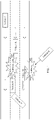
- a vehicle A moves on a road surface
- the vehicle A is further surrounded by a vehicle B and a vehicle C
- the vehicle A, the vehicle B, and the vehicle C move in a same direction on respective lanes.
- a vehicle (vehicle D) moves toward the vehicle B from one side.
- the vehicle A calculates a possibility that the vehicle D will not collide with the vehicle A in a future time period. Therefore, the vehicle A is not warned.
- an actual situation is that the vehicle D may collide with the vehicle B in the future time period.
- a speed and position of the vehicle B or the vehicle D instantaneously change rapidly.
- the position of the vehicle B or the vehicle D deviates after the collision, and may be very close to the vehicle A (relative to a speed of the vehicle A).
- a response time that can be left for a driver of the vehicle A may not be sufficient to avoid the vehicle B or the vehicle D after the collision. Consequently, the vehicle A will also collide with the vehicle B or the vehicle D.
- the vehicle A may identify, in advance by using the ego-vehicle warning method provided in this embodiment of this application, that the vehicle B or the vehicle D will collide with the vehicle A after the vehicle D collides with the vehicle B, and the vehicle A is warned, so that the driver of the vehicle A performs prevention or avoidance in advance, to improve driving safety of the vehicle driven by the user.
- the ego-vehicle warning method provided in this embodiment of this application is: obtaining a vehicle in a surrounding nearby area in which the ego-vehicle moves, and calculating a collision risk between the vehicle in the nearby area of the ego-vehicle and another vehicle; and if a collision between the vehicle in the nearby area of the ego-vehicle and the another vehicle causes a collision risk to the ego-vehicle, warning the ego-vehicle, so that the ego-vehicle knows in advance the collision risk caused to the another vehicle by the vehicle in the nearby area of the ego-vehicle other than a factor of the ego-vehicle and notes a series of possible accidents in advance and can avoid the accidents (for example, decelerate in advance) in advance.
- the ego-vehicle warning method refer to the following description in the embodiment corresponding to FIG. 3 .
- FIG. 1 is merely an example scenario diagram.
- a quantity of vehicles shown in FIG. 1 is not limited in this embodiment of this application.
- the scenario in FIG. 1 may further include other devices.
- the driving safety driving scenario may further include a roadside unit (roadside unit, RSU), and the like.
- the RSU is deployed on a roadside.
- the RSU is mainly configured to collect moving information of a vehicle, and send the collected information to the vehicle.
- the vehicle and the RSU may communicate with each other by using a radio link.
- names of the devices in FIG. 1 are not limited.
- the devices may also have other names.
- the names are replaced with names of network elements having same or similar functions. This is not limited.
- FIG. 2a is a schematic diagram of a structure of a vehicle according to an embodiment of this application.
- the vehicle may include a warning apparatus 101, a vehicle gateway 102, and a vehicle-mounted antenna 103. Further, the vehicle may further include an audio electronic control unit (electronic control unit, ECU) 104, an indicator 105, or the like. Components included in the vehicle may be connected to each other by using a CAN bus.
- ECU electronic control unit
- the structure shown in FIG. 2a does not constitute a specific limitation on the vehicle.
- the vehicle may include more or fewer components than those shown in the figure, or combine some components, or split some components, or have different component arrangements.
- the vehicle may further include a telematics box (telematics box, T-box), a domain controller (domain controller, DC), a multi-domain controller (multi-domain controller, MDC), a user interface (for example, a touch display screen), or the like.
- the components shown in FIG. 2a may be implemented by using hardware, software, or a combination of software and hardware, for example, an Internet of Vehicles chip. A specific structure of the warning apparatus 101 is described in detail in the embodiment shown in FIG. 2a .
- the warning apparatus 101 may be configured to perform the ego-vehicle warning method provided in this embodiment of this application.
- the specific structure of the warning apparatus 101 is described in detail in the embodiment shown in FIG. 2b .
- the vehicle gateway 102 is mainly configured to receive and send vehicle information.
- the vehicle gateway 41 may be connected to the warning apparatus 101 by using a CAN bus connection.
- the vehicle gateway 41 may receive alarm information from the warning apparatus 101, send the alarm information to the audio ECU 104 or the indicator 105, and send an alarm prompt to a driver by using the audio ECU 104 or the indicator 105.
- the vehicle-mounted antenna 103 may be a built-in V2X communications antenna and a GNSS communications antenna.
- the V2X communications antenna is responsible for radio signal transmission and reception such as V2X communication.
- the GNSS communications antenna is responsible for receiving positioning data sent by a GNSS.
- the audio ECU 104 may be configured to externally play back information in a form of sound, or receive an instruction sent by a user, or the like.
- the indicator 105 may have a plurality of colors. Different information content may be conveyed to the driver by using different colors of the indicator 105.
- FIG. 2b is a schematic diagram of a structure of a warning apparatus 101 according to an embodiment of this application.
- the warning apparatus 101 may include a global navigation satellite system (global navigation satellite system, GNSS) receiver 1011, a V2X radio transceiver (modem) 1012, a micro control unit (micro control unit, MCU) 1013, and a CAN processor 1014. Further, the warning apparatus 101 may further include a memory 1015 and a power management module 1016.
- GNSS global navigation satellite system
- modem V2X radio transceiver
- MCU micro control unit
- the structure shown in FIG. 2b does not constitute a specific limitation on the warning apparatus.
- the warning apparatus may include more or fewer components than those shown in the figure, or combine some components, or split some components, or have different component arrangements.
- the components shown in the figure may be implemented by using hardware, software, or a combination of software and hardware.
- the GNSS receiver 1011 is responsible for receiving a GNSS signal.
- the GNSS receiver 1011 may provide a wireless communications solution applied to the warning apparatus 101 and including a GNSS or the like.
- the GNSS receiver 1011 may be one or more devices integrating at least one communications processing module.
- the GNSS receiver 1011 receives an electromagnetic wave by using the GNSS communications antenna, performs frequency modulation and filtering processing on the electromagnetic wave signal, and sends the processed signal to the MCU 1013.
- the GNSS may include a global satellite positioning system (global positioning system, GPS), a global navigation satellite system (global navigation satellite system, GLONASS), a BeiDou navigation satellite system (BeiDou navigation satellite system, BDS), a quasi-zenith satellite system (quasi-zenith satellite system, QZSS), and/or a satellite based augmentation system (satellite based augmentation system, SBAS), or the like. This is not limited.
- GPS global positioning system
- GLONASS global navigation satellite system
- BeiDou navigation satellite system BeiDou navigation satellite system
- BDS BeiDou navigation satellite system
- QZSS quasi-zenith satellite system
- SBAS satellite based augmentation system
- the V2X radio transceiver 1012 is responsible for transmitting and receiving V2X information.
- the V2X radio transceiver 1012 may provide a wireless communications solution applied to the warning apparatus 101 and including V2X or the like.
- the V2X radio transceiver 1012 may include at least one filter, a switch, a power amplifier, a low noise amplifier (low noise amplifier, LNA), or the like.
- the V2X radio transceiver 1012 may receive an electromagnetic wave by using the V2X communications antenna, perform processing such as filtering and amplification on the received electromagnetic wave, and send the processed signal to the MCU 1013.
- the V2X radio transceiver 1012 may further amplify a signal modulated by a modem processor.
- the V2X radio transceiver 1012 may further receive a to-be-sent signal from the CAN processor 1014, perform frequency modulation and amplification on the signal, convert the signal into an electromagnetic wave by using the V2X communications antenna, and radiate the electromagnetic wave.
- the GNSS receiver 1011 and the GNSS communications antenna are coupled, and the V2X radio transceiver 1012 and the V2X communications antenna are coupled, so that the warning apparatus 101 communicates with a network and another device by using a GNSS satellite communications technology and a V2X communications technology.
- the MCU 1013 is responsible for performing, based on the positioning data obtained from the GNSS receiver 1011 and position information that is of a vehicle surrounding the ego-vehicle and that is obtained from the V2X radio transceiver 1012, the ego-vehicle warning method provided in this embodiment of this application.
- the CAN processor 1014 receives vehicle information data, including a vehicle alarm, a start signal, a brake signal, a turn signal, an accelerator signal, and the like.
- the CAN processor 1014 may include one or more processing units.
- the CAN processor 1014 may include an application processor (application processor, AP), a modem processor, a graphics processing unit (graphics processing unit, GPU), an image signal processor (image signal processor, ISP), a controller, a memory, a video codec, a digital signal processor (digital signal processor, DSP), a baseband processor, and/or a neural-network processing unit (neural-network processing unit, NPU).
- Different processing units may be independent components, or may be integrated into one or more processors.
- the CAN processor 1014 may be a nerve center and a command center of the warning apparatus.
- the controller may generate an operation control signal based on instruction operation code and a time sequence signal, to complete control of instruction reading and instruction execution.
- the CAN processor 1014 may be further provided with a memory, configured to store instructions and data.
- the memory in the CAN processor 1014 is a cache memory.
- the memory may store instructions or data just used or cyclically used by the CAN processor 1014.
- the memory 1015 may be configured to store computer executable program code, and the executable program code includes instructions. By running the instructions and data stored in the memory 1015, the CAN processor 1014 may perform various function applications and data processing of the warning apparatus 101. For example, in this embodiment, the CAN processor 1014 may send alarm information to the driver based on a time T of a shortest distance between a remote vehicle and a nearby vehicle that is stored in the memory 1015.
- the memory 1015 may include a data storage area and a program storage area.
- the data storage area is configured to store corresponding data.
- the memory 1015 may include a highspeed random access memory, and may further include a non-volatile memory, for example, at least one magnetic storage device, a flash (flash) memory device, a UFS, or an eMMC.
- the power management module 1016 is connected to the CAN processor 1014, and connected to a power supply by using a power supply and grounding terminal.
- the power management module 1016 receives a power input, and supplies power to the CAN processor 1014 or the like.
- the V2X radio transceiver 1012, the MCU 1013, and the CAN processor 1014 may be integrated in a chip module (or referred to as a system-on-chip).
- the chip system may include a chip, or may include a chip and another discrete component.
- a vehicle described in the following embodiment may have the components shown in FIG. 2a
- a warning apparatus described in the following embodiment may have the components shown in FIG. 2b .
- FIG. 3 is an ego-vehicle warning method according to an embodiment of this application.
- the ego-vehicle warning method is performed by a warning apparatus.
- the warning apparatus may have the components shown in FIG. 2 .
- the method may include the following steps.
- Step 301 Determine a nearby area of an ego-vehicle based on moving information of the ego-vehicle.
- the ego-vehicle may be any vehicle in the scenario shown in FIG. 1 .
- the moving information of the ego-vehicle includes a current moving speed v of the ego-vehicle, a heading of the ego-vehicle, and a yawing rate of the ego-vehicle.
- the warning apparatus may obtain the moving information of the ego-vehicle from a GNSS by using a GNSS receiver.
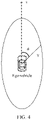
- the nearby area of the ego-vehicle may be an elliptical area.
- the nearby area of the ego-vehicle may be formed by a set of position points whose distances to the ego-vehicle (or a center of the ego-vehicle) are less than a preset threshold.
- An area other than the nearby area may be referred to as a non-nearby area of the ego-vehicle.
- the preset threshold may be set based on a requirement. When a distance from a position point to the ego-vehicle is less than the preset threshold, it indicates that the position point is relatively close to the ego-vehicle, and may be referred to as a nearby point of the ego-vehicle.
- the determining a nearby area of an ego-vehicle based on moving information of the ego-vehicle may include: determining the nearby area of the ego-vehicle based on a deceleration a of the ego-vehicle, a response time ⁇ t of a driver, a safety distance A, the current moving speed v of the ego-vehicle, the heading of the ego-vehicle, and the yawing rate of the ego-vehicle.
- Y is a distance from an edge point of the nearby area of the ego-vehicle to the ego-vehicle (or a center point of the ego-vehicle); a indicates the deceleration when the driver of the ego-vehicle realizes that the deceleration is needed, and a may be a preset fixed value (for example, -3.6 m/S ⁇ 2); ⁇ t indicates the response time of the driver of the ego-vehicle, and ⁇ t may be a fixed value (for example, 3 seconds); t is the time for the driver of the ego-vehicle to decelerate from the current moving speed v of the ego-vehicle to 0 when the driver of the ego-vehicle realizes that the
- FIG. 4 shows the nearby area of the ego-vehicle.
- the nearby area of the ego-vehicle increases when the moving speed v of the ego-vehicle increases, and decreases when the moving speed v of the ego-vehicle decreases.
- the deceleration a of the ego-vehicle, the response time ⁇ t of the driver, and the safety distance A are preset based on experience or adjusted by a user based on a requirement.
- Step 302 Perform target classification on vehicles surrounding the ego-vehicle to obtain nearby vehicles in a plurality of directions and remote vehicle sets in the plurality of directions.
- the plurality of directions may be eight directions relative to the ego-vehicle, for example, may include a front side of the ego-vehicle, a front left side of the ego-vehicle, a front right side of the ego-vehicle, a left side of the ego-vehicle, a right side of the ego-vehicle, a rear side of the ego-vehicle, a rear left side of the ego-vehicle, and a rear right side of the ego-vehicle.
- a horizontal coordinate system is established by using the ego-vehicle as a center.
- a moving direction of the ego-vehicle is an x-axis.
- the x-axis points to the moving direction of the ego-vehicle.
- a y-axis is perpendicular to the x-axis and points to a right side of the ego-vehicle.
- the front side of the ego-vehicle may be an area within a range of [-5 degrees, + 5 degrees).
- the front right side of the ego-vehicle may be an area within a range of [+ 5 degrees, 80 degrees).
- the right side of the ego-vehicle may be an area within a range of [80 degrees, 100 degrees).
- the rear right side of the ego-vehicle may be an area within a range of [100 degrees, 175 degrees).
- the rear side of the ego-vehicle may be an area within a range of [175 degrees, 185 degrees).
- the rear left side of the ego-vehicle may be an area within a range of [185 degrees, 260 degrees).
- the left side of the ego-vehicle may be an area within a range of [260 degrees, 280 degrees).
- the front left side of the ego-vehicle may be an area within a range of [280 degrees, 355 degrees).
- a nearby vehicle in each direction is a vehicle closest to the ego-vehicle in the nearby area in the direction, or may be described as a vehicle that is located in the nearby area of the ego-vehicle in the direction and associated with the ego-vehicle during moving (having a potential collision risk with the ego-vehicle) and closest to the ego-vehicle.
- the nearby vehicle may also be defined as a nearby vehicle relative to the ego-vehicle. It may be understood that there is a maximum of one nearby vehicle in each direction only, and there may be no nearby vehicle (that is, no nearby vehicle exists).
- a remote vehicle set in each direction includes a remote vehicle located outside the nearby area in the direction, or the remote vehicle may be described as a vehicle located in the non-nearby area of the ego-vehicle in the direction and associated with the ego-vehicle during moving (having a potential collision risk with the ego-vehicle). It may be understood that there may be a plurality of remote vehicles, that is, the remote vehicle may be one or more vehicles. Certainly, there may be no remote vehicle associated with the ego-vehicle in a direction. This is not limited.
- the performing target classification on vehicles surrounding the ego-vehicle to obtain nearby vehicles in a plurality of directions and remote vehicle sets in the plurality of directions may include: after determining the nearby area of the ego-vehicle, obtaining, by the warning apparatus, information about the vehicles surrounding the ego-vehicle (for example, moving speeds, position information, and heading information of the vehicles); determining vehicle sets in the plurality of directions based on the moving information of the vehicles surrounding the ego-vehicle and a vehicle kinematics algorithm, where a vehicle set in each of the plurality of directions includes a vehicle that is located in the direction and associated with the ego-vehicle among the vehicles surrounding the ego-vehicle; and determining a vehicle that is in the vehicle set and is located in the nearby area of the ego-vehicle and closest to the ego-vehicle as a nearby vehicle, and determining a vehicle that is in the vehicle set and is located outside the nearby area as a remote vehicle in the remote vehicle
- the warning apparatus may receive, through V2X communication, a basic safety message (basic safety message, BSM) packet sent by a vehicle surrounding the ego-vehicle, where the BSM packet carries an identity (identity, ID) of the surrounding vehicle, and a moving speed, position information, heading information, and the like of the surrounding vehicle.
- BSM basic safety message
- the warning apparatus may receive, by using a V2X radio transceiver, a BSM packet sent by the surrounding vehicle, and parse the received BSM packet to obtain information such as the ID of the surrounding vehicle, and the moving speed, position information, and heading information of the surrounding vehicle.
- the surrounding vehicle may obtain the moving speed, position information, heading information, and the like of the surrounding vehicle by using the prior art. Details are not described herein again.
- the vehicle kinematics algorithm may be any method for screening out the nearby vehicle and the remote vehicle relative to the ego-vehicle. There may be a plurality of algorithms for implementing this function.
- the vehicle kinematics algorithm may be a target classification algorithm or another algorithm. In the description of this embodiment of this application, it is assumed that the vehicle kinematics algorithm is the target classification algorithm. For a specific implementation process of the target classification algorithm, refer to the following description in a first scenario of the method shown in FIG. 3 .
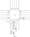
- a vehicle 1 and a vehicle 2 are located in the nearby area of the ego-vehicle, and a vehicle 3, a vehicle 4, and a vehicle 5 are located in the non-nearby area of the ego-vehicle; if the vehicle 1 and the vehicle 2 are associated with the ego-vehicle, and the vehicle 1 is a vehicle that is located on the front side of the ego-vehicle and closest to the ego-vehicle, the vehicle 1 is a nearby vehicle on the front side; if the vehicle 2 is a vehicle that is located on the rear right side of the ego-vehicle and closest to the ego-vehicle, the vehicle 2 is a nearby vehicle on the rear right side; if the vehicle 3 and the vehicle 4 are associated with the ego-vehicle, the vehicle 3 is a remote vehicle on the front right side, and the vehicle 4 is a remote vehicle on the rear side of the ego-vehicle; if the vehicle 5
- Step 303 For any remote vehicle, calculate a shortest distance between the remote vehicle and a nearby vehicle in each direction that matches a direction of the remote vehicle in the plurality of directions in a future time period, and record a time T when the shortest distance is less than a threshold D.
- the direction of the remote vehicle and the direction matching the direction of the remote vehicle satisfy a collision direction matching rule, and the collision direction matching rule may be preconfigured on the warning apparatus based on experience.
- the collision direction matching rule may be shown in Table 1. If the remote vehicle is located on the rear side, directions matching the direction of the remote vehicle include five directions: the right side, the left side, the rear left side, the rear right side, and the rear side. If the remote vehicle is located on the rear left side, directions matching the direction of the remote vehicle include five directions: the front left side, the left side, the rear left side, the rear right side, and the rear side. If the remote vehicle is located on the front left side, directions matching the direction of the remote vehicle include five directions: the front side, the left side, the front right side, the rear left side, and the front left side.
- directions matching the direction of the remote vehicle include five directions: the front right side, the front side, the right side, the rear right side, and the front left side. If the remote vehicle is located on the front side, directions matching the direction of the remote vehicle include five directions: the front right side, the left side, the front rear side, the right side, and the front side. If the remote vehicle is located on the left side, directions matching the direction of the remote vehicle include five directions: the front left side, the left side, the rear left side, the front side, and the rear side. If the remote vehicle is located on the right side, directions matching the direction of the remote vehicle include five directions: the right side, the front right side, the rear right side, the front side, and the rear side.
- directions matching the direction of the remote vehicle include five directions: the right side, the rear left side, the rear side, the front right side, and the rear side.
- Table 1 Direction of the remote vehicle Directions matching the direction of the remote vehicle Rear side Right side, left side, rear left side, rear right side, and rear side Rear left side Front left side, left side, rear left side, rear right side, and rear side Front left side Front side, left side, front right side, rear left side, and front left side Front right side Front right side Front right side, front side, right side, rear right side, and front left side Front side Front right side Front right side, left side, front rear side, right side, and front left side Front side Front right side, left side, front rear side, right side, and front side Left side Front left side, left side, rear left side, front side, and rear side Right side Right side Right side Right side, front right side, rear right side, front side, and rear side Rear right side Right side, rear left side, rear side, front right side, and rear side Rear right side Right side, rear left
- calculating a shortest distance between the nearby vehicle in the direction and the remote vehicle in a future time period includes:
- the moving information of the remote vehicle may include the current moving position of the remote vehicle, a moving speed v of the remote vehicle, a predicted curvature R of the remote vehicle, a heading a of the remote vehicle, and the like.
- the current moving position of the remote vehicle may be obtained by a GPS of the remote vehicle.
- the moving speed v of the remote vehicle is obtained by a speed sensor of the remote vehicle.
- the heading a of the remote vehicle may be obtained from GPS positioning data of the remote vehicle.
- the moving information of the nearby vehicle may include the current moving position of the nearby vehicle, a moving speed v of the nearby vehicle, a predicted curvature R of the nearby vehicle, a heading a of the nearby vehicle, and the like.
- the current moving position of the nearby vehicle may be obtained by a GPS of the nearby vehicle.
- the moving speed v of the nearby vehicle is obtained by a speed sensor of the nearby vehicle.
- the heading a of the nearby vehicle may be obtained from GPS positioning data of the nearby vehicle.
- the future time period may be set based on a requirement.
- the future time period may be set to a fixed value based on experience, for example, set to 10 seconds (s).
- the threshold D may be set based on a requirement. This is not limited.
- the shortest distance between the remote vehicle and the nearby vehicle in the direction matching the direction of the remote vehicle is greater than or equal to the threshold D, it indicates that there is no collision risk between the remote vehicle and the nearby vehicle in the direction matching the direction of the remote vehicle. In this case, there is no predicted collision time between the remote vehicle and the nearby vehicle in the direction matching the direction of the remote vehicle, and no recording is performed. In the future time period, if the shortest distance between the remote vehicle and the nearby vehicle in the direction matching the direction of the remote vehicle is less than the threshold D, it indicates that there is no collision risk between the remote vehicle and the nearby vehicle in the direction matching the direction of the remote vehicle.
- the path collision prediction algorithm (path predication method) is intended to predict a future longitude and latitude position of the vehicle and an expression in the future time period based on running data and a predicted curvature R of the vehicle.
- the path collision prediction algorithm may be the following formula (2).
- x t and y t are moving positions of the vehicle in a future time period t
- x 0 and y 0 are current moving positions of the vehicle
- v is the moving speed of the vehicle
- R is the predicted curvature
- R is equal to a ratio of the moving speed v of the vehicle to a yawing angular velocity of the vehicle
- ⁇ is a yawing angle of the vehicle
- the yawing angle of the vehicle is an included angle between the heading a of the vehicle and the due north direction.
- calculating the shortest distance between the remote vehicle and the nearby vehicle in the direction matching the direction of the remote vehicle may include: sequentially calculating, at a plurality of times in the future time period based on the formula (2), moving positions of the remote vehicle and moving positions of the nearby vehicle matching the remote vehicle, using distance differences between the moving positions of the remote vehicle and the moving positions of the remote vehicle as distance values between the remote vehicle and the nearby vehicle in the direction matching the direction of the remote vehicle, and using a smallest distance value among the distance values between the remote vehicle and the nearby vehicle as the shortest distance between the remote vehicle and the nearby vehicle in the direction matching the direction of the remote vehicle.
- the plurality of times in the future time period may be 0.1s, 0.2s, 0.3s, ..., and 10s.
- the warning apparatus may first calculate a distance value between the remote vehicle and the nearby vehicle in the direction matching the direction of the remote vehicle at 0.1s, then calculate a distance value between the remote vehicle and the nearby vehicle in the direction matching the direction of the remote vehicle at 0.2s, then calculate a distance value between the remote vehicle and the nearby vehicle in the direction matching the direction of the remote vehicle at 0.3s, and so on, until all distance values between the remote vehicle and the nearby vehicle in the direction matching the direction of the remote vehicle are calculated, and then taking a smallest distance value from the calculation results as the shortest distance between the remote vehicle and the nearby vehicle in the direction matching the direction of the remote vehicle.
- Step 304 Send alarm information to the driver of the ego-vehicle based on the nearby vehicle corresponding to the earliest time T among all recorded times T.
- the nearby vehicle corresponding to the earliest time T among the times T when the shortest distance is less than the threshold D may be a most risky vehicle in the nearby area of the ego-vehicle.
- the alarm information is used to indicate to the driver that an accidental collision accident not caused by the ego-vehicle or another accidental collision accident may occur in the direction of the nearby vehicle corresponding to the earliest time T. Further, the driver may be prompted to drive carefully, or slow down, or change to a left/right lane.
- the alarm information may be information in a form of a sound wave.
- the warning apparatus may send the alarm information to the driver of the ego-vehicle by using an audio ECU in the ego-vehicle.
- the warning apparatus may send the alarm information to the driver by using an indicator.
- an indicator is disposed in a position that can be easily seen by the driver, and the indicator may emit yellow light.
- the warning apparatus may trigger turn-on of the indicator based on the nearby vehicle corresponding to the earliest time T among the times T when the shortest distance is less than the threshold D, that is, turn on the small yellow indicator, to send the alarm information to the driver.
- the driver is prompted that an accidental collision accident not caused by the ego-vehicle or another accidental collision accident may occur in the direction of the nearby vehicle corresponding to the earliest time T among the times T when the shortest distance is less than the threshold D, so that the driver drives carefully.
- the alarm information may indicate to the driver that a vehicle surrounding the ego-vehicle is at risk of colliding with the remote vehicle, and that the risk may affect the ego-vehicle, so that the driver drives carefully. There is no need to specify a direction in which a vehicle may have a collision risk.
- the alarm information may be sent to the driver by using a combination of the audio ECU and a user interface (user interface, UI).
- the warning apparatus may send, to the driver of the ego-vehicle by using the audio ECU in the ego-vehicle, that an accidental collision accident not caused by the ego-vehicle or another accidental collision accident may occur, so that the driver drives carefully.
- the warning apparatus displays the direction of the nearby vehicle corresponding to the earliest time T on the UI, so that the driver knows in which direction a danger is likely to occur.
- the alarm information may alternatively be sent to the driver by using a combination of the indicator and the UI.
- the warning apparatus may trigger turn-on of the indicator, to indicate to the driver that an accidental collision accident not caused by the ego-vehicle or another accidental collision accident may occur, so that the driver drives carefully.
- the warning apparatus displays the direction of the nearby vehicle corresponding to the earliest time T on the UI, so that the driver knows in which direction a danger is likely to occur.
- nearby vehicles associated with the ego-vehicle include ⁇ vehicle 1, vehicle 2 ⁇ , where the vehicle 1 is located on the front side, and the vehicle 2 is located on the rear side; and remote vehicles associated with the ego-vehicle include ⁇ vehicle 3, vehicle 4 ⁇ , where the vehicle 3 is located on the front right side, and the vehicle 4 is located on the rear side.
- the nearby vehicles in the direction matching the direction of the vehicle 3 include ⁇ vehicle 1, vehicle 2 ⁇
- the nearby vehicles in the direction matching the direction of the vehicle 4 include ⁇ vehicle 2 ⁇ .
- a distance between the vehicle 3 and the vehicle 1 at 0.1s and a distance between the vehicle 3 and the vehicle 1 at 0.2s are iteratively calculated based on the formula (2), until all distances between the vehicle 3 and the vehicle 1 within 10s are calculated, and a time T1 when the shortest distance between the vehicle 3 and the vehicle 1 is less than the threshold D is recorded.
- a time T2 when the shortest distance between the vehicle 3 and the vehicle 2 is less than the threshold D is calculated and recorded
- a time T3 when the shortest distance between the vehicle 4 and the vehicle 2 is less than the threshold D is calculated and recorded.
- T1, T2, and T3 are compared. If T2 is the earliest, the driver is prompted that a danger may occur on the rear right side of the vehicle 2 corresponding to T2, so that the driver drives carefully.
- a nearby vehicle and a remote vehicle surrounding the ego-vehicle and associated with the ego-vehicle may be determined, and a collision risk between vehicles surrounding the ego-vehicle is analyzed in advance based on the collision direction matching rule and the path collision prediction algorithm. For example, the time T when the shortest distance between the nearby vehicle and the remote vehicle is less than the threshold D is calculated and recorded, the vehicle corresponding to the earliest time T among the times T when the shortest distance is less than the threshold D is used as the most risky vehicle in the nearby area of the ego-vehicle, and the driver is prompted to note the risk.
- the target classification algorithm (target classification method) is an existing algorithm. Assuming that the ego-vehicle is the ego-vehicle and that the directions relative to the ego-vehicle are eight directions, the target classification algorithm is described in detail as follows: receiving moving information of other vehicles surrounding the ego-vehicle; using the other vehicles surrounding the ego-vehicle as target vehicles;
- a target vehicle satisfies any one or more of the following conditions (1) to (3), it is determined that the target vehicle is a vehicle not associated with the ego-vehicle: (1) If the target vehicle moves opposite the ego-vehicle and is located on the left side, the right side, the rear left side, the rear right side, or the rear side, and a heading angle difference is greater than ⁇ 80 degrees, it is determined that the target vehicle is a vehicle not associated with the ego-vehicle.
- the target vehicle moves in the same direction as the ego-vehicle and is located on the front side, the front left side, or the front right side, and the speed v ⁇ sin ⁇ of the target vehicle minus the moving speed v of the ego-vehicle is greater than 0, it is determined that the target vehicle is a vehicle not associated with the ego-vehicle.
- the target vehicle moves in the same direction as the ego-vehicle and is located on the rear side, the rear left side, or the rear right side, and the speed v of the ego-vehicle minus the speed v ⁇ sin ⁇ of the target vehicle is greater than 0, it is determined that the target vehicle is a vehicle not associated with the ego-vehicle.
- ⁇ arctan (AC/ BC) , a longitude and latitude of the target vehicle are (x1, y1), a longitude and latitude of the ego-vehicle are (x0, y0), AC is equal to y1-y0, and BC is equal to x1-x0.
- the deceleration a, the response time ⁇ t of the driver, and the safety distance A in the formula (1) may be preset based on experience or adjusted by the user based on a requirement, so that the user can adjust the nearby area of the vehicle based on an appropriate driving level of the user and obtain a more suitable and accurate warning and reminding effect based on the specified nearby area.
- the deceleration a, the response time ⁇ t of the driver, and the safety distance A may be set based on an actual requirement of the driver (for example, the driving level of the driver).
- the driver may input the deceleration a, the response time ⁇ t of the driver, and the safety distance A into the ego-vehicle through a human-machine interaction interface of the ego-vehicle based on a situation of the driver, so that the warning apparatus determines the nearby area of the ego-vehicle based on the input speed a, response time ⁇ t of the driver, and safety distance A, and the formula (1).
- the warning apparatus may periodically calculate, by using the method shown in FIG. 3 , the nearby vehicle corresponding to the earliest time T among the times T when the shortest distance is less than the threshold D, and send alarm information based on a calculation result.
- the period may be set to 100 milliseconds or another time length. This is not limited. Assuming that the period is 100 milliseconds, the warning apparatus may perform, once every 100 milliseconds, the ego-vehicle warning method shown in FIG. 3 .
- the warning apparatus may cancel the alarm information based on a moving status of the vehicle, and initiate new alarm information. Specifically, the method is shown in FIG. 7A and FIG. 7B .
- FIG. 7A and FIG. 7B are a flowchart of another ego-vehicle warning method according to an embodiment of this application. As shown in FIG. 7A and FIG. 7B , the method is performed by a warning apparatus, and the method may include the following steps.
- Step 701 In a first period, a warning apparatus performs the method shown in FIG. 3 to obtain a nearby vehicle corresponding to an earliest time T among times T when a shortest distance is less than a threshold D, and sends alarm information based on the nearby vehicle corresponding to the earliest time T among the times T when the shortest distance is less than the threshold D.
- step 701 refer to step 304. Details are not described again.
- Step 702 In a next period adjacent to the first period, for example, in a second period, the warning apparatus recalculates a nearby area of an ego-vehicle.
- step 301 For a method for recalculating the nearby area of the ego-vehicle by the warning apparatus, refer to step 301. Details are not described again.
- Step 703 The warning apparatus determines, based on a target classification algorithm, nearby vehicles located in the nearby area of the ego-vehicle and remote vehicle sets located in a non-nearby area in the second period, and determines whether the nearby vehicle corresponding to the earliest time T among the times T when the shortest distance is less than the threshold D in the first period is included in the determined nearby vehicles in the nearby area of the ego-vehicle.
- step 704 If the nearby vehicle corresponding to the earliest time T among the times T when the shortest distance is less than the threshold D in the first period is not included in the nearby vehicles in the nearby area of the ego-vehicle, alarm cancellation information is sent, and step 704 is performed; or if the nearby vehicle corresponding to the earliest time T among the times T when the shortest distance is less than the threshold D in the first period is included in the nearby vehicles in the nearby area of the ego-vehicle, step 704 is performed.
- the alarm cancellation information may be used to indicate to a driver that an accident in a direction of the nearby vehicle corresponding to the earliest time T among the times T when the shortest distance is less than the threshold D is cleared. For example, if the nearby vehicle corresponding to the earliest time T among the times T when the shortest distance is less than the threshold D in the first period is a vehicle 2, and the vehicle 2 is located on a rear right side of the ego-vehicle, the alarm cancellation information may indicate to the driver that an accident on the rear right side of the driver is cleared.
- the warning apparatus may send the alarm cancellation information to the driver of the ego-vehicle by using an audio ECU in the ego-vehicle; or the warning apparatus sends the alarm cancellation information to the driver by turning off an indicator.
- the nearby vehicles located in the nearby area of the ego-vehicle and remote vehicles located in the non-nearby area in the second period refer to step 301. Details are not described again.
- Step 704 For any remote vehicle in the second period, calculate a shortest distance between the remote vehicle and a nearby vehicle in each direction that matches a direction of the remote vehicle in a plurality of directions in a future time period, and record a time T when the shortest distance is less than the threshold D.
- step 704 refer to step 303. Details are not described again.
- Step 705 Determine whether the calculated nearby vehicle corresponding to the earliest time T among the times T when the shortest distance is less than the threshold D in the second period is the same as the calculated nearby vehicle corresponding to the earliest time T among the times T when the shortest distance is less than the threshold D in the first period, that is, determine whether the most threatening vehicle in the nearby area of the ego-vehicle is the original vehicle; and if the calculated nearby vehicle corresponding to the earliest time T among the times T when the shortest distance is less than the threshold D in the second period is different from the nearby vehicle corresponding to the earliest time T among the times T when the shortest distance is less than the threshold D in the first period, send new alarm information; otherwise, keep the alarm information in step 701 unchanged.
- the new alarm information may be used to indicate that an accidental collision accident not caused by the ego-vehicle or another accidental collision accident may occur in the direction of the nearby vehicle corresponding to the earliest time T among the times T when the shortest distance is less than the threshold D in the second period, so that the driver drives carefully.
- step 303 For example, for a manner in which the warning apparatus sends the new alarm information, refer to the description in step 303. Details are not described again.
- the warning apparatus may periodically detect whether there is a threatening vehicle surrounding the ego-vehicle, feed back a direction of a most threatening vehicle to the driver, prompt the driver that there is a danger in the direction, so that the driver drives carefully, and when the threat is cleared, cancel an alarm, thereby improving vehicle driving safety.
- the warning apparatus includes corresponding hardware structures and/or software modules for performing the functions.
- a person skilled in the art should easily be aware that, in combination with the examples described in the embodiments disclosed in this specification, algorithms steps may be implemented by hardware or a combination of hardware and computer software. Whether a function is implemented by hardware or hardware driven by computer software depends on particular applications and design constraints of the technical solutions. A person skilled in the art may use different methods to implement the described functions for each particular application, but it should not be considered that the implementation goes beyond the scope of this application.
- the warning apparatus may be divided into functional modules based on the foregoing method examples.
- each functional module may be obtained through division based on each corresponding function, or two or more functions may be integrated into one processing module.
- the integrated module may be implemented in a form of hardware, or may be implemented in a form of a software functional module.
- module division is an example, and is merely logical function division. In actual implementation, another division manner may be used.
- FIG. 8 is a schematic diagram of composition of a warning apparatus 80 according to an embodiment of this application.
- the warning apparatus 80 may be a functional module in an ego-vehicle, or a chip or a system-on-chip in an ego-vehicle. As shown in FIG. 8 , the warning apparatus 80 may include a processing unit 801 and a sending unit 802.
- the processing unit 801 is configured to: determine a nearby area of the ego-vehicle based on moving information of the ego-vehicle; perform target classification on vehicles surrounding the ego-vehicle to obtain nearby vehicles in a plurality of directions and remote vehicle sets in the plurality of directions, where a nearby vehicle in each direction is a vehicle closest to the ego-vehicle in the nearby area in the direction, and a remote vehicle set in each direction includes a remote vehicle located outside the nearby area in the direction; and for any remote vehicle, calculate a shortest distance between the remote vehicle and a nearby vehicle in each direction that matches a direction of the remote vehicle in the plurality of directions in a future time period, and record, in a memory, a time T when the shortest distance is less than a threshold D.
- the processing unit 801 supports the warning apparatus 80 in performing step 301, step 302, and step 303.
- the sending unit 802 is configured to send alarm information to a driver of the ego-vehicle based on a nearby vehicle corresponding to an earliest time T among all recorded times T, where the alarm information is used to indicate to the driver that an accidental collision accident not caused by the ego-vehicle or another accidental collision accident may occur in a direction of the nearby vehicle corresponding to the earliest time T.
- the sending unit 802 supports the warning apparatus 80 in performing step 304.
- the warning apparatus 80 is configured to perform each step of the ego-vehicle warning methods shown in FIG. 3 and FIG. 7A and FIG. 7B , and can achieve a same effect as the foregoing ego-vehicle warning methods.
- the processing unit 801 in FIG. 8 may be replaced with an MCU, and the MCU may integrate functions of the processing unit 801.
- the sending unit 802 in FIG. 8 may be replaced with a CAN processor, and the CAN processor may integrate functions of the sending unit 802.
- the warning apparatus 80 shown in FIG. 8 may further include a memory.
- the warning apparatus 80 in this embodiment of this application may be the warning apparatus shown in FIG. 2b .
- the disclosed apparatus and method may be implemented in other manners.
- the described apparatus embodiments are merely examples.
- division into the modules or units is merely logical function division.
- a plurality of units or components may be combined or may be integrated into another apparatus, or some features may be ignored or not be performed.
- the displayed or discussed mutual couplings or direct couplings or communication connections may be implemented through some interfaces.
- the indirect couplings or communication connections between the apparatuses or units may be implemented in electronic, mechanical, or other forms.
- the units described as separate components may be or may not be physically separate, and components displayed as units may be one or more physical units, that is, may be located in one place, or may be distributed in a plurality of different places. Some or all of the units may be selected based on actual requirements to achieve the objectives of the solutions in the embodiments.
- functional units in the embodiments of this application may be integrated into one processing unit, or each of the units may exist alone physically, or two or more units are integrated into one unit.
- the integrated unit may be implemented in a form of hardware, or may be implemented in a form of a software functional unit.
- the integrated unit When the integrated unit is implemented in a form of a software functional unit and sold or used as an independent product, the integrated unit may be stored in a readable storage medium.
- the software product is stored in a storage medium and includes several instructions for instructing a device (which may be a single-chip microcomputer, a chip, or the like) or a processor (processor) to perform all or some of the steps of the methods described in the embodiments of this application.
- the foregoing storage medium includes: any medium that can store program code, such as a USB flash drive, a removable hard disk, a ROM, a RAM, a magnetic disk, or an optical disc.
Landscapes
- Engineering & Computer Science (AREA)
- Automation & Control Theory (AREA)
- Mechanical Engineering (AREA)
- Physics & Mathematics (AREA)
- Transportation (AREA)
- Human Computer Interaction (AREA)
- Remote Sensing (AREA)
- Radar, Positioning & Navigation (AREA)
- General Physics & Mathematics (AREA)
- Mathematical Physics (AREA)
- Electromagnetism (AREA)
- Computer Networks & Wireless Communication (AREA)
- Traffic Control Systems (AREA)
Applications Claiming Priority (2)
| Application Number | Priority Date | Filing Date | Title |
|---|---|---|---|
| CN201910792798.0A CN110588510B (zh) | 2019-08-26 | 2019-08-26 | 一种对本车的预警方法及装置 |
| PCT/CN2020/111510 WO2021037087A1 (zh) | 2019-08-26 | 2020-08-26 | 一种对本车的预警方法及装置 |
Publications (2)
| Publication Number | Publication Date |
|---|---|
| EP4002323A1 true EP4002323A1 (de) | 2022-05-25 |
| EP4002323A4 EP4002323A4 (de) | 2022-07-27 |
Family
ID=68855757
Family Applications (1)
| Application Number | Title | Priority Date | Filing Date |
|---|---|---|---|
| EP20856199.3A Pending EP4002323A4 (de) | 2019-08-26 | 2020-08-26 | Verfahren und vorrichtung zur frühwarnung für ein vorhandenes fahrzeug |
Country Status (4)
| Country | Link |
|---|---|
| US (1) | US11807261B2 (de) |
| EP (1) | EP4002323A4 (de) |
| CN (1) | CN110588510B (de) |
| WO (1) | WO2021037087A1 (de) |
Families Citing this family (17)
| Publication number | Priority date | Publication date | Assignee | Title |
|---|---|---|---|---|
| CN110588510B (zh) * | 2019-08-26 | 2021-09-07 | 华为技术有限公司 | 一种对本车的预警方法及装置 |
| CN111426326B (zh) * | 2020-01-17 | 2022-03-08 | 深圳市镭神智能系统有限公司 | 一种导航方法、装置、设备、系统及存储介质 |
| JP7259775B2 (ja) * | 2020-01-27 | 2023-04-18 | いすゞ自動車株式会社 | ふらつき警報装置およびふらつき警報制御方法 |
| CN111323042B (zh) * | 2020-02-20 | 2023-10-10 | 华为技术有限公司 | 目标物体的预警方法、装置和电子设备 |
| CN111326019A (zh) * | 2020-02-27 | 2020-06-23 | 腾讯科技(深圳)有限公司 | 驾驶风险预警方法及装置、计算机介质和电子设备 |
| TWI766254B (zh) * | 2020-03-18 | 2022-06-01 | 崑山科技大學 | 車輛警示方法 |
| CN111613092B (zh) * | 2020-05-09 | 2023-10-27 | 腾讯科技(深圳)有限公司 | 车辆碰撞预警方法、装置、设备及计算机可读存储介质 |
| CN111653124A (zh) * | 2020-05-15 | 2020-09-11 | 腾讯科技(深圳)有限公司 | 数据处理方法、装置、电子设备及存储介质 |
| CN113808435B (zh) * | 2020-06-11 | 2024-03-12 | 奥迪股份公司 | 用于车辆的辅助装置、相应的方法及存储介质 |
| US20220258755A1 (en) * | 2021-02-16 | 2022-08-18 | Toyota Research Institute, Inc. | Directional stimuli to enhance vehicle operator situational awareness |
| CN115223394A (zh) * | 2021-04-20 | 2022-10-21 | 北京航迹科技有限公司 | 一种预警方法、装置、设备、存储介质和程序产品 |
| CN113269990B (zh) * | 2021-07-16 | 2021-10-15 | 宁波均联智行科技股份有限公司 | 一种车辆碰撞的预警方法及车辆控制系统 |
| CN113619578A (zh) * | 2021-07-28 | 2021-11-09 | 东风汽车集团股份有限公司 | 一种车辆防碰撞方法、防碰撞系统和计算机可读存储介质 |
| CN113793535B (zh) * | 2021-09-15 | 2022-06-21 | 智道网联科技(北京)有限公司 | 并存交通风险的告警方法、装置和计算机可读存储介质 |
| CN114115174B (zh) * | 2021-10-27 | 2022-06-24 | 北京云汉通航科技有限公司 | 一种高速警用预警车的故障处理方法、系统及装置 |
| CN115424474B (zh) * | 2022-11-04 | 2023-02-14 | 联友智连科技有限公司 | 一种基于v2x和rsu的左转辅助预警方法 |
| CN116259194A (zh) * | 2023-03-21 | 2023-06-13 | 阿维塔科技(重庆)有限公司 | 一种车辆防碰撞方法及装置、设备、存储介质 |
Family Cites Families (25)
| Publication number | Priority date | Publication date | Assignee | Title |
|---|---|---|---|---|
| DE102004028822B4 (de) * | 2004-06-15 | 2006-07-06 | Daimlerchrysler Ag | Verfahren zur Erkennung einer Ausrichtungsänderung eines Umgebungsfahrzeugs |
| US20090228172A1 (en) * | 2008-03-05 | 2009-09-10 | Gm Global Technology Operations, Inc. | Vehicle-to-vehicle position awareness system and related operating method |
| US20120041632A1 (en) | 2010-08-12 | 2012-02-16 | Robert Bosch Gmbh | Combined lane change assist and rear, cross-traffic alert functionality |
| US9187118B2 (en) * | 2011-12-30 | 2015-11-17 | C & P Technologies, Inc. | Method and apparatus for automobile accident reduction using localized dynamic swarming |
| US9495874B1 (en) * | 2012-04-13 | 2016-11-15 | Google Inc. | Automated system and method for modeling the behavior of vehicles and other agents |
| JP5867273B2 (ja) * | 2012-04-27 | 2016-02-24 | 富士通株式会社 | 接近物体検知装置、接近物体検知方法及び接近物体検知用コンピュータプログラム |
| KR101382873B1 (ko) * | 2012-06-29 | 2014-04-08 | 엘지이노텍 주식회사 | 전방차량 충돌 경고 시스템 및 전방차량 충돌 경고 방법 |
| WO2014024294A1 (ja) * | 2012-08-09 | 2014-02-13 | トヨタ自動車 株式会社 | 車両の警報装置 |
| US20140176714A1 (en) * | 2012-12-26 | 2014-06-26 | Automotive Research & Test Center | Collision prevention warning method and device capable of tracking moving object |
| CN103144633B (zh) | 2012-12-27 | 2016-03-02 | 中国科学技术大学苏州研究院 | 基于车联网技术的追尾碰撞预警方法 |
| DE102013214233B4 (de) * | 2013-07-19 | 2015-02-05 | Honda Motor Co., Ltd. | Intelligentes Vorwärtskollisionswarnsystem |
| DE102015103361A1 (de) * | 2014-03-22 | 2015-09-24 | Ford Global Technologies, Llc | Verkehrsdichte-empfindlichkeitswähler |
| CN104753691B (zh) * | 2015-02-27 | 2018-02-09 | 同济大学 | 基于车车协作的车联网紧急消息多跳广播传输方法 |
| CN104882025B (zh) | 2015-05-13 | 2017-02-22 | 东华大学 | 一种基于车联网技术的碰撞检测预警方法 |
| JP2017030435A (ja) * | 2015-07-30 | 2017-02-09 | クラリオン株式会社 | 車間距離制御装置 |
| US9908468B2 (en) * | 2016-01-12 | 2018-03-06 | Toyota Motor Engineering & Manufacturing North America, Inc. | Apparatus and method for providing an extended forward collision warning |
| DE102016203086B4 (de) | 2016-02-26 | 2018-06-28 | Robert Bosch Gmbh | Verfahren und Vorrichtung zur Fahrerassistenz |
| CN106781692B (zh) | 2016-12-01 | 2020-09-04 | 东软集团股份有限公司 | 车辆碰撞预警的方法、装置及系统 |
| JP6610585B2 (ja) * | 2017-03-13 | 2019-11-27 | トヨタ自動車株式会社 | 衝突回避制御装置 |
| CN206684953U (zh) | 2017-04-09 | 2017-11-28 | 兰州工业学院 | 一种基于车联网的汽车防碰撞预警系统 |
| JP6848794B2 (ja) * | 2017-09-29 | 2021-03-24 | トヨタ自動車株式会社 | 衝突回避支援装置 |
| CN109147394A (zh) | 2018-11-12 | 2019-01-04 | 安徽江淮汽车集团股份有限公司 | 交叉路口的车辆碰撞预警方法 |
| CN109872567A (zh) * | 2019-03-01 | 2019-06-11 | 浙江吉利汽车研究院有限公司 | 车辆前向碰撞预警方法、装置及设备 |
| CN110111602B (zh) * | 2019-04-30 | 2021-01-19 | 浙江吉利控股集团有限公司 | 一种车辆碰撞预警方法、装置及设备 |
| CN110588510B (zh) * | 2019-08-26 | 2021-09-07 | 华为技术有限公司 | 一种对本车的预警方法及装置 |
-
2019
- 2019-08-26 CN CN201910792798.0A patent/CN110588510B/zh active Active
-
2020
- 2020-08-26 EP EP20856199.3A patent/EP4002323A4/de active Pending
- 2020-08-26 WO PCT/CN2020/111510 patent/WO2021037087A1/zh unknown
- 2020-08-26 US US17/635,809 patent/US11807261B2/en active Active
Also Published As
| Publication number | Publication date |
|---|---|
| US20220289223A1 (en) | 2022-09-15 |
| WO2021037087A1 (zh) | 2021-03-04 |
| EP4002323A4 (de) | 2022-07-27 |
| CN110588510A (zh) | 2019-12-20 |
| US11807261B2 (en) | 2023-11-07 |
| CN110588510B (zh) | 2021-09-07 |
Similar Documents
| Publication | Publication Date | Title |
|---|---|---|
| EP4002323A1 (de) | Verfahren und vorrichtung zur frühwarnung für ein vorhandenes fahrzeug | |
| US11312378B2 (en) | System and method for vehicle control using vehicular communication | |
| US11338813B2 (en) | System and method for merge assist using vehicular communication | |
| TWI751974B (zh) | 專用短程通訊(dsrc)中的安全事件訊息傳輸定時 | |
| US9922565B2 (en) | Sensor fusion of camera and V2V data for vehicles | |
| US9889847B2 (en) | Method and system for driver assistance for a vehicle | |
| JP2018111490A (ja) | 無線車両データに基づく車両緩和システム | |
| DE102019205607A1 (de) | Systeme und Verfahren für vorausschauenden Spurwechsel | |
| CN111483457A (zh) | 用于避免碰撞的装置、系统和方法 | |
| CN111055840A (zh) | 车辆对基础设施(v2i)消息传递系统 | |
| US20170025001A1 (en) | Fusion of non-vehicle-to-vehicle communication equipped vehicles with unknown vulnerable road user | |
| JP5673646B2 (ja) | 周辺車両認識装置 | |
| WO2017187884A1 (ja) | 推奨走行速度提供プログラム、走行支援システム、車両制御装置および自動走行車両 | |
| EP4129787A1 (de) | Auswahlverfahren für ein schlüsselziel, vorrichtung und system | |
| US20240149915A1 (en) | Classification and prioritization of objects for autonomous driving | |
| JP2017033403A (ja) | 運転支援装置 | |
| WO2020177647A1 (zh) | 一种利用无线电信号进行目标物探测的方法及相关装置 | |
| US20180232967A1 (en) | Information processing device, information processing method, computer program product, and moving object | |
| CN117416375A (zh) | 车辆避让方法、装置、设备及存储介质 | |
| JP2018139031A (ja) | 情報提供装置、情報提供方法およびコンピュータプログラム | |
| US20220410904A1 (en) | Information processing device, information processing system and information processing method | |
| Tang | Pedestrian protection using the integration of v2v communication and pedestrian automatic emergency braking system | |
| WO2017154517A1 (ja) | 送信装置、通信システム | |
| JP2017125702A (ja) | 物体検出装置 | |
| WO2023015505A1 (zh) | 一种车辆驾驶方法、装置及系统 |
Legal Events
| Date | Code | Title | Description |
|---|---|---|---|
| STAA | Information on the status of an ep patent application or granted ep patent |
Free format text: STATUS: THE INTERNATIONAL PUBLICATION HAS BEEN MADE |
|
| PUAI | Public reference made under article 153(3) epc to a published international application that has entered the european phase |
Free format text: ORIGINAL CODE: 0009012 |
|
| STAA | Information on the status of an ep patent application or granted ep patent |
Free format text: STATUS: REQUEST FOR EXAMINATION WAS MADE |
|
| 17P | Request for examination filed |
Effective date: 20220216 |
|
| AK | Designated contracting states |
Kind code of ref document: A1 Designated state(s): AL AT BE BG CH CY CZ DE DK EE ES FI FR GB GR HR HU IE IS IT LI LT LU LV MC MK MT NL NO PL PT RO RS SE SI SK SM TR |
|
| A4 | Supplementary search report drawn up and despatched |
Effective date: 20220629 |
|
| RIC1 | Information provided on ipc code assigned before grant |
Ipc: B60W 30/095 20120101ALI20220623BHEP Ipc: B60Q 9/00 20060101ALI20220623BHEP Ipc: G08G 1/16 20060101AFI20220623BHEP |
|
| DAV | Request for validation of the european patent (deleted) | ||
| DAX | Request for extension of the european patent (deleted) | ||
| REG | Reference to a national code |
Ref country code: DE Ref legal event code: R079 Free format text: PREVIOUS MAIN CLASS: G08G0001160000 Ipc: B60W0040114000 |
|
| GRAP | Despatch of communication of intention to grant a patent |
Free format text: ORIGINAL CODE: EPIDOSNIGR1 |
|
| STAA | Information on the status of an ep patent application or granted ep patent |
Free format text: STATUS: GRANT OF PATENT IS INTENDED |
|
| RIC1 | Information provided on ipc code assigned before grant |
Ipc: B60W 30/095 20120101ALI20240322BHEP Ipc: G08G 1/16 20060101ALI20240322BHEP Ipc: B60Q 9/00 20060101ALI20240322BHEP Ipc: G01S 17/931 20200101ALI20240322BHEP Ipc: G01S 13/931 20200101ALI20240322BHEP Ipc: B60W 50/14 20200101ALI20240322BHEP Ipc: B60W 40/114 20120101AFI20240322BHEP |
|
| INTG | Intention to grant announced |
Effective date: 20240412 |