EP4000149B1 - Elektrische leiteranordnung - Google Patents
Elektrische leiteranordnung Download PDFInfo
- Publication number
- EP4000149B1 EP4000149B1 EP20746896.8A EP20746896A EP4000149B1 EP 4000149 B1 EP4000149 B1 EP 4000149B1 EP 20746896 A EP20746896 A EP 20746896A EP 4000149 B1 EP4000149 B1 EP 4000149B1
- Authority
- EP
- European Patent Office
- Prior art keywords
- yarn
- insulating jacket
- conductor
- section
- conductor assembly
- Prior art date
- Legal status (The legal status is an assumption and is not a legal conclusion. Google has not performed a legal analysis and makes no representation as to the accuracy of the status listed.)
- Active
Links
Images

Classifications
-
- H—ELECTRICITY
- H02—GENERATION; CONVERSION OR DISTRIBUTION OF ELECTRIC POWER
- H02G—INSTALLATION OF ELECTRIC CABLES OR LINES, OR OF COMBINED OPTICAL AND ELECTRIC CABLES OR LINES
- H02G15/00—Cable fittings
- H02G15/02—Cable terminations
- H02G15/06—Cable terminating boxes, frames or other structures
- H02G15/064—Cable terminating boxes, frames or other structures with devices for relieving electrical stress
- H02G15/068—Cable terminating boxes, frames or other structures with devices for relieving electrical stress connected to the cable shield only
-
- H—ELECTRICITY
- H01—ELECTRIC ELEMENTS
- H01B—CABLES; CONDUCTORS; INSULATORS; SELECTION OF MATERIALS FOR THEIR CONDUCTIVE, INSULATING OR DIELECTRIC PROPERTIES
- H01B7/00—Insulated conductors or cables characterised by their form
- H01B7/17—Protection against damage caused by external factors, e.g. sheaths or armouring
- H01B7/18—Protection against damage caused by wear, mechanical force or pressure; Sheaths; Armouring
-
- H—ELECTRICITY
- H05—ELECTRIC TECHNIQUES NOT OTHERWISE PROVIDED FOR
- H05K—PRINTED CIRCUITS; CASINGS OR CONSTRUCTIONAL DETAILS OF ELECTRIC APPARATUS; MANUFACTURE OF ASSEMBLAGES OF ELECTRICAL COMPONENTS
- H05K9/00—Screening of apparatus or components against electric or magnetic fields
- H05K9/0073—Shielding materials
- H05K9/0081—Electromagnetic shielding materials, e.g. EMI, RFI shielding
- H05K9/009—Electromagnetic shielding materials, e.g. EMI, RFI shielding comprising electro-conductive fibres, e.g. metal fibres, carbon fibres, metallised textile fibres, electro-conductive mesh, woven, non-woven mat, fleece, cross-linked
-
- H—ELECTRICITY
- H01—ELECTRIC ELEMENTS
- H01B—CABLES; CONDUCTORS; INSULATORS; SELECTION OF MATERIALS FOR THEIR CONDUCTIVE, INSULATING OR DIELECTRIC PROPERTIES
- H01B1/00—Conductors or conductive bodies characterised by the conductive materials; Selection of materials as conductors
- H01B1/20—Conductive material dispersed in non-conductive organic material
-
- H—ELECTRICITY
- H01—ELECTRIC ELEMENTS
- H01B—CABLES; CONDUCTORS; INSULATORS; SELECTION OF MATERIALS FOR THEIR CONDUCTIVE, INSULATING OR DIELECTRIC PROPERTIES
- H01B13/00—Apparatus or processes specially adapted for manufacturing conductors or cables
- H01B13/22—Sheathing; Armouring; Screening; Applying other protective layers
-
- H—ELECTRICITY
- H01—ELECTRIC ELEMENTS
- H01B—CABLES; CONDUCTORS; INSULATORS; SELECTION OF MATERIALS FOR THEIR CONDUCTIVE, INSULATING OR DIELECTRIC PROPERTIES
- H01B13/00—Apparatus or processes specially adapted for manufacturing conductors or cables
- H01B13/22—Sheathing; Armouring; Screening; Applying other protective layers
- H01B13/26—Sheathing; Armouring; Screening; Applying other protective layers by winding, braiding or longitudinal lapping
-
- H—ELECTRICITY
- H01—ELECTRIC ELEMENTS
- H01B—CABLES; CONDUCTORS; INSULATORS; SELECTION OF MATERIALS FOR THEIR CONDUCTIVE, INSULATING OR DIELECTRIC PROPERTIES
- H01B17/00—Insulators or insulating bodies characterised by their form
- H01B17/56—Insulating bodies
- H01B17/58—Tubes, sleeves, beads, or bobbins through which the conductor passes
-
- H—ELECTRICITY
- H01—ELECTRIC ELEMENTS
- H01B—CABLES; CONDUCTORS; INSULATORS; SELECTION OF MATERIALS FOR THEIR CONDUCTIVE, INSULATING OR DIELECTRIC PROPERTIES
- H01B7/00—Insulated conductors or cables characterised by their form
- H01B7/0009—Details relating to the conductive cores
-
- H—ELECTRICITY
- H01—ELECTRIC ELEMENTS
- H01B—CABLES; CONDUCTORS; INSULATORS; SELECTION OF MATERIALS FOR THEIR CONDUCTIVE, INSULATING OR DIELECTRIC PROPERTIES
- H01B7/00—Insulated conductors or cables characterised by their form
- H01B7/02—Disposition of insulation
-
- H—ELECTRICITY
- H01—ELECTRIC ELEMENTS
- H01B—CABLES; CONDUCTORS; INSULATORS; SELECTION OF MATERIALS FOR THEIR CONDUCTIVE, INSULATING OR DIELECTRIC PROPERTIES
- H01B7/00—Insulated conductors or cables characterised by their form
- H01B7/17—Protection against damage caused by external factors, e.g. sheaths or armouring
- H01B7/28—Protection against damage caused by moisture, corrosion, chemical attack or weather
- H01B7/2806—Protection against damage caused by corrosion
-
- H—ELECTRICITY
- H02—GENERATION; CONVERSION OR DISTRIBUTION OF ELECTRIC POWER
- H02G—INSTALLATION OF ELECTRIC CABLES OR LINES, OR OF COMBINED OPTICAL AND ELECTRIC CABLES OR LINES
- H02G15/00—Cable fittings
- H02G15/08—Cable junctions
- H02G15/18—Cable junctions protected by sleeves, e.g. for communication cable
- H02G15/184—Cable junctions protected by sleeves, e.g. for communication cable with devices for relieving electrical stress
-
- H—ELECTRICITY
- H05—ELECTRIC TECHNIQUES NOT OTHERWISE PROVIDED FOR
- H05K—PRINTED CIRCUITS; CASINGS OR CONSTRUCTIONAL DETAILS OF ELECTRIC APPARATUS; MANUFACTURE OF ASSEMBLAGES OF ELECTRICAL COMPONENTS
- H05K9/00—Screening of apparatus or components against electric or magnetic fields
- H05K9/0073—Shielding materials
- H05K9/0098—Shielding materials for shielding electrical cables
-
- H—ELECTRICITY
- H01—ELECTRIC ELEMENTS
- H01B—CABLES; CONDUCTORS; INSULATORS; SELECTION OF MATERIALS FOR THEIR CONDUCTIVE, INSULATING OR DIELECTRIC PROPERTIES
- H01B17/00—Insulators or insulating bodies characterised by their form
- H01B17/56—Insulating bodies
- H01B17/60—Composite insulating bodies
Definitions
- the invention relates to an electrical conductor arrangement comprising an electrical conductor, an electrically insulating sheath arranged around at least one conductor section of the conductor, and an electrically conductive sheath arranged around an insulating sheath section of the insulating sheath.
- Such conductor arrangements are used in and/or on many electrical devices, for example, in electrical feedthroughs through housing openings or on cables, where the electrically conductive sheath of a conductor arrangement serves, for example, to shield against electric fields.
- a particular weak point of such a conductor arrangement is the area where the sheath ends around the insulating jacket. In this area, high field strengths of an electric field at the end of the sheath, which acts as an electrical electrode, can lead to significant discharges (“sparks") on the surface of the insulating jacket, which can damage or destroy the insulating jacket in a short time. This effect is further amplified if the end of the sheath has sharp edges, because small radii of an edge of the sheath lead to particularly high electric field strengths in the area surrounding the edge.
- field control Measures that influence local electric field strengths are referred to as field control.
- Elements for field control are referred to as field control elements.
- different measures are used. For example, it may be sufficient to make the radii of an electrode large enough to keep the field strength at the interface below the electrical strength of the insulating sheath. This type of field control is referred to as geometric field control.
- weakly conductive coatings in the form of varnishes, tapes, or filled plastics can be applied to the surface of the insulating sheath as field control elements.
- the electric field drives a current through these materials, which, together with their resistance, leads to a voltage drop.
- This voltage drop defines the potential along the surface.
- This type of field control is called resistive field control.
- the field strength for alternating voltage is not constant along such a system, since part of the current flows capacitively via the insulating sheath to the conductor of the conductor arrangement. As a result, the voltage drop is lower further away from the sheath. This can be counteracted by reducing the resistance along the length of the field control element.
- Another possibility is to use materials whose conductivity is strongly dependent on the applied field strength. At particularly exposed areas, such materials become more conductive, further reducing the field strength. This type of field control is called nonlinear field control.
- refractive materials with a high relative permittivity can be used for AC systems. These materials "break” the electric field at their interface with the insulation, thus pushing it away from the electrode edge. This type of field control is called refractive field control.
- a termination for a plastic-insulated power cable is known. This includes a field control cone with a continuous conductor wire embedded in its sheath.
- From the DE 17 77 892 U is a device for the production of terminations for high-voltage cables, high-voltage bushings for transformers, converters, or the like, made of castable, curable, or self-curing insulating compounds with conductive inserts for potential control.
- Concentric rings made of conductive materials, particularly metal, can be inserted into the mold before the compound is poured. The rings can be secured in the mold by webs or threads made of an insulating material with chemical and physical properties corresponding to the casting compound.
- the invention is based on the object of providing an electrical conductor arrangement of the type described above with a simple, to specify precise field control that can be adapted to the respective requirements, in particular for electrical bushings and cables.
- an electrical conductor arrangement having the features of claim 1
- An electrical conductor arrangement comprises an electrical conductor, an electrically insulating sheath arranged around at least one conductor section of the conductor, an electrically conductive sheath arranged around a first insulating sheath section of the insulating sheath, and an electrically conductive yarn wound around a second insulating sheath section of the insulating sheath adjacent to the first insulating sheath section for electrical field control.
- a winding device is used, in particular, for winding.
- a rotational movement is performed for winding. For example, the conductor arrangement is rotated with the insulating sheath.
- the yarn (the electrically conductive yarn) can be wound directly onto the insulating sheath.
- the yarn (the electrically conductive yarn) is or will therefore be wound directly onto the insulating sheath.
- An electrical conductor arrangement thus comprises an electrically conductive yarn for field control.
- the yarn is wound around an insulating sheath section of an insulating sheath, which surrounds an adjacent insulating sheath section between a conductor and an electrically conductive sheath of the conductor arrangement.
- the yarn is used as a field control element for an electric field at the end of the electrically conductive sheath.
- a yarn end portion of the yarn is connected to a sheath end portion of the sheath, for example, by gluing. This advantageously fixes a yarn end portion of the yarn near the sheath end portion of the sheath, and the yarn is electrically coupled to the sheath galvanically and/or capacitively.
- the yarn is wound helically around the second insulating sheath section.
- the helical winding of the yarn can have different pitches.
- the pitch of the helical winding and its variation along the course of the winding allow the electrical resistance of the winding and its local variation in a direction parallel to the conductor to be flexibly adapted to the respective field control requirements.
- the yarn has a lower specific electrical conductivity than the sheath.
- the wound yarn has an electrical resistance in the range between 1 M ⁇ /m and 100 M ⁇ /m.
- the yarn is made of a polyamide fiber which is surrounded by an electrically conductive coated with a carbon-containing material, or made of a fiber mixture comprising at least one polyamide fiber and one electrically conductive carbon fiber, or of a metallic fiber.
- the yarn is surrounded by a protective layer or protective sheath.
- a protective layer or protective sheath advantageously protects the yarn against mechanical and/or chemical damage.
- the dielectric strength of the system consisting of the yarn and the protective layer or protective sheath can be increased.
- the yarn is fixed to the second insulating sheath section by a hardening or hardenable resin.
- a hardening or hardenable resin advantageously stabilizes the yarn and protects it against local and global mechanical displacements.
- the local pitches of the winding can be fixed.
- a curing or curable resin is applied to the second insulating sheath section to fix the yarn to the second insulating sheath section, and the yarn is wound around the second insulating sheath section before the resin on the resin has completely cured.
- An electrical feedthrough according to the invention through a housing opening of a housing of an electrical device has a conductor arrangement according to the invention, the Sheath is electrically connected to the housing and is guided through the housing opening with the conductor and the insulating sheath.
- a cable according to the invention has a conductor arrangement according to the invention.
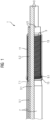
- FIG 1 shows an embodiment of an electrical conductor arrangement 1 according to the invention in a partially sectioned view, wherein the upper part of the FIG 1
- the conductor assembly 1 is shown in section.
- the conductor assembly 1 comprises an electrical conductor 3, an electrically insulating insulating jacket 5, an electrically conductive sheath 7, an electrically conductive yarn 9 for electric field control, a resin layer 11, and a protective layer 13.
- the insulating jacket 5 is arranged around a conductor section 3.1 of the conductor 3.
- the sheath 7 is arranged around a first insulating jacket section 5.1 of the insulating jacket 5.
- the resin layer 11 is applied to an outer surface of a second insulating jacket section 5.2 of the insulating jacket 5, which section is adjacent to the first insulating jacket section 5.1.
- the yarn 9 is wound helically around the second insulating jacket section 5.2 on the resin layer 11.
- the resin layer 11 fixes the yarn 9 to the second insulating jacket section 5.2.
- a yarn end section 9.1 of the yarn 9 is electrically conductively connected to a sheath end section 7.1 of the sheath 7 and is firmly fixed to the sheath end section 7.1 by an adhesive 15.
- the sheath end section 7.1 has an outer diameter that tapers conically towards the second insulating jacket section 5.2.
- the protective layer 13 is arranged around the yarn 9 and the resin layer 11.
- the protective layer 13 is shown transparent, but
- the conductor 3 is made of copper, for example.
- the insulating sheath 5 is made of polyetheretherketone (PEEK), cross-linked polyethylene (VPE), polyvinyl chloride (PVC) or a comparable polymer, oil-paper, ceramic, silicone, resin-impregnated mica tapes, or synthetic resin.
- the sheath 7 is made of stainless steel, for example.
- the yarn 9 is made of a polyamide fiber encased in an electrically conductive carbon-containing material, a fiber mixture comprising at least one polyamide fiber and one electrically conductive carbon fiber, or a thin metallic fiber.
- the resin layer 11 is made of a curing or hardening resin, for example, epoxy resin.
- the protective layer 13 is also made of a curing or hardening resin, for example, in particular of the same resin as the resin layer 11.
- the yarn 9 has a lower specific electrical conductivity than the sheath 7.
- the wound Yarn 9 has an electrical resistance in the range between 1 M ⁇ /m and 100 M ⁇ /m.
- a base body is first produced, comprising the conductor 3, the insulating sheath 5, and the sheath 7.
- Resin for the resin layer 11 is then applied to the second insulating sheath section 5.2.
- the yarn 9 is then wound around the sheath end section 7.1 and the second insulating sheath section 5.2, pressed against the resin, and bonded to the sheath end section 7.1 by the adhesive 15.
- material for the protective layer 13 is applied to the yarn 9 and the resin layer 11.
- FIG 2 shows a partially sectioned illustration of an embodiment of an electrical feedthrough 17 according to the invention through a housing opening 19.1 of an electrically conductive housing 19 of an electrical device.
- the electrical device is, for example, an electrical machine such as a motor, a generator or a transformer, or an electrical switching device such as a circuit breaker or a disconnector.
- the feedthrough 17 comprises a FIG 1 formed conductor arrangement 1 and a seal 21.
- the housing 19 and the seal 21 are shown in section, the conductor arrangement 1 is as in Figure 1 shown partially in section.
- the insulating sheath section 5.2 of the conductor arrangement 1 is arranged within the housing 19.
- the sleeve 7 protrudes from the housing opening 19.1.
- the seal 21 runs annularly around the sleeve 7, connects the sleeve 7 in an electrically conductive manner to the housing 19, and seals the housing opening 19.1.
- the sleeve 7 is made of a material containing graphite.
- the conductor 3 is connected or connectable to a current path of the electrical equipment (in the case that the electrical equipment is an electrical machine, the conductor 3 is connected, for example, to a winding of the machine; in the case that the electrical equipment is an electrical switching device, the conductor 3 for example, connected to a switching contact of the switching device).
- the shell 7 and the housing 19 are connected, for example, to earth potential.
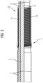
- FIG 3 shows analogous to FIG 1 a partially sectioned view of an embodiment of a cable 23 according to the invention.
- the cable 23 comprises a FIG 1 formed conductor arrangement 1, which forms a first cable end of the cable 23, wherein the insulating sheath 5 extends around the conductor 3 to a (not shown) second cable end of the cable 23.
- the second cable end can be formed like the first cable end.
- the Figures 1 to 3 The exemplary embodiments of conductor arrangements 1 shown can be modified in various ways.
- the helical winding of the yarn 9 can have locally different pitches in order to change the electrical resistance of the winding along its course and to adapt it to the requirements of field control.
- a protective sheath instead of a protective layer 13, a protective sheath can be provided which envelops the yarn 9 and the resin layer 11.
- Further exemplary embodiments of a conductor arrangement 1 according to the invention have no resin layer 11 and/or no protective layer 13 at all.
- the yarn 9 is not electrically connected to the sheath 7, but is only capacitively coupled to the sheath 7.
Landscapes
- Engineering & Computer Science (AREA)
- Manufacturing & Machinery (AREA)
- Microelectronics & Electronic Packaging (AREA)
- Physics & Mathematics (AREA)
- Electromagnetism (AREA)
- Textile Engineering (AREA)
- Chemical & Material Sciences (AREA)
- Spectroscopy & Molecular Physics (AREA)
- Dispersion Chemistry (AREA)
- Insulators (AREA)
- Insulated Conductors (AREA)
- Communication Cables (AREA)
- Insulating Bodies (AREA)
Description
- Die Erfindung betrifft eine elektrische Leiteranordnung mit einem elektrischen Leiter, einem wenigstens um einen Leiterabschnitt des Leiters herum angeordneten elektrisch isolierenden Isoliermantel und einer elektrisch leitfähigen Hülle, die um einen Isoliermantelabschnitt des Isoliermantels herum angeordnet ist.
- Derartige Leiteranordnungen werden in und/oder an vielen elektrischen Betriebsmitteln, beispielsweise in elektrischen Durchführungen durch Gehäuseöffnungen, oder an Kabeln eingesetzt, wobei die elektrisch leitfähige Hülle einer Leiteranordnung beispielsweise zum Abschirmen elektrischer Felder dient. Eine besondere Schwachstelle einer derartigen Leiteranordnung ist der Bereich, in dem die Hülle um den Isoliermantel endet. In diesem Bereich kann es aufgrund hoher Feldstärken eines elektrischen Feldes am Ende der als elektrische Elektrode wirkenden Hülle zu erheblichen Entladungen ("Funken") auf der Oberfläche des Isoliermantels kommen, die den Isoliermantel in kurzer Zeit beschädigen oder zerstören können. Dieser Effekt wird weiter verstärkt, wenn das Ende der Hülle scharfkantig ausgeführt ist, weil kleine Radien einer Kante der Hülle in der Umgebung der Kante zu besonders hohen elektrischen Feldstärken führen.
- Maßnahmen, die die lokalen elektrischen Feldstärken beeinflussen, werden als Feldsteuerung bezeichnet. Elemente zur Feldsteuerung werden als Feldsteuerelemente bezeichnet. Je nach Anforderung an die Feldsteuerung werden verschiedene Maßnahmen eingesetzt. So kann es zum Beispiel ausreichen, die Radien einer Elektrode groß genug auszuführen, um die Feldstärke an der Grenzfläche unterhalb der elektrischen Festigkeit des Isoliermantels zu halten. Diese Art der Feldsteuerung wird als geometrische Feldsteuerung bezeichnet.
- Alternativ können als Feldsteuerelemente schwach leitfähige Beläge in Form von Lacken, Bändern, oder gefüllten Kunststoffen auf die Oberfläche des Isoliermantels aufgebracht werden. Das elektrische Feld treibt einen Strom durch diese Stoffe, der zusammen mit ihrem Widerstand zu einem Spannungsabfall führt. Dieser Spannungsabfall wiederum definiert das Potenzial entlang der Oberfläche. Je präziser der Widerstand eingestellt werden kann, desto präziser kann das Potenzial und damit das Feld gesteuert werden. Diese Art der Feldsteuerung wird als resistive Feldsteuerung bezeichnet. Entlang eines solchen Systems ist die Feldstärke bei Wechselspannung jedoch nicht konstant, da ein Teil des Stroms kapazitiv über den Isoliermantel zum Leiter der Leiteranordnung fließt. Dadurch fällt der Spannungsabfall weiter von der Hülle entfernt geringer aus. Dem kann entgegengewirkt werden, indem der Widerstand über die Länge des Feldsteuerelements gesenkt wird.
- Eine weitere Möglichkeit besteht darin, Materialien zu verwenden, deren Leitfähigkeit eine starke Abhängigkeit von der anliegenden Feldstärke zeigt. An besonders feldstärkebelasteten Stellen werden solche Stoffe leitfähiger, wodurch die Feldstärke weiter reduziert wird. Diese Art der Feldsteuerung wird als nichtlineare Feldsteuerung bezeichnet.
- Alternativ können für Wechselspannungssysteme so genannte refraktive Materialien verwendet werden, die eine hohe relative Permittivität haben. Diese Stoffe "brechen" das elektrische Feld an ihrer Grenzfläche zur Isolierung und drängen es somit weg von der Elektrodenkante. Diese Art der Feldsteuerung wird als refraktive Feldsteuerung bezeichnet.
- Aus der
DE 77 22 352 U1 ist ein Endverschluss eines kunststoffisolierten Starkstromkabels bekannt. Daraus ist ein Feldsteuerungstrichter bekannt, in dessen Mantel ein durchgehender Leitungsdraht eingebettet ist. - Aus der
DE 17 77 892 U ist eine Vorrichtung zur Herstellung von Endverschlüssen für Hochspannungskabel, Hochspannungsdurchführen für Transformatoren, Wandlern oder dergleichen aus gießbaren, härtbaren oder selbsthärtenden Isoliermassen mit leitenden Einlagen zur Potentialsteuerung, bekannt. In die Gießform können vor dem Eingießen der Masse konzentrische Ringe aus leitenden Stoffen, insbesondere Metall, eingelegt werden. Die Ringe können durch Stege oder Fäden aus einem Isolierstoff mit der Gießmasse entsprechenden chemischen und physikalischen Eigenschaften in der Form festgelegt werden. - Der Erfindung liegt die Aufgabe zugrunde, eine elektrische Leiteranordnung der oben beschriebenen Art mit einer einfach, präzise und den jeweiligen Anforderungen anpassbar realisierbaren Feldsteuerung, insbesondere für elektrische Durchführungen und Kabel, anzugeben.
- Die Aufgabe wird erfindungsgemäß durch eine elektrische Leiteranordnung mit den Merkmalen des Anspruchs 1, ein Verfahren zum Herstellen einer elektrischen Leiteranordnung mit den Merkmalen des Anspruchs 10, eine elektrische Durchführung mit den Merkmalen des Anspruchs 11 und ein Kabel mit den Merkmalen des Anspruchs 12 gelöst.
- Vorteilhafte Ausgestaltungen der Erfindung sind Gegenstand der Unteransprüche.
- Eine erfindungsgemäße elektrische Leiteranordnung umfasst einen elektrische Leiter, einen wenigstens um einen Leiterabschnitt des Leiters herum angeordneten elektrisch isolierenden Isoliermantel, eine elektrisch leitfähige Hülle, die um einen ersten Isoliermantelabschnitt des Isoliermantels herum angeordnet ist, und ein elektrisch leitfähiges Garn, das zur elektrischen Feldsteuerung um einen an den ersten Isoliermantelabschnitt angrenzenden zweiten Isoliermantelabschnitt des Isoliermantels gewickelt ist. Zum Wickeln wird insbesondere ein Wickelgerät verwendet. Zum Wickeln wird eine Rotationsbewegung ausgeführt. Rotiert wird beispielsweise die Leiteranordnung mit dem Isoliermantel. Es ist beispielsweise auch möglich beim Wickeln die Leiteranordnung mit dem Isoliermantel zu fixieren und das Garn mittels einer sich rotierenden Vorrichtung um die Leiteranordnung auf den Isoliermantel zu wickeln. Das Garn (das elektrisch leitfähige Garn) ist direkt auf den Isoliermantel wickelbar. Das Garn (das elektrisch leitfähige Garn) ist bzw. wird also direkt auf den Isoliermantel gewickelt.
- Eine erfindungsgemäße elektrische Leiteranordnung weist also ein elektrisch leitfähiges Garn zur Feldsteuerung auf. Das Garn ist um einen Isoliermantelabschnitt eines Isoliermantels gewickelt, der einen daran angrenzenden Isoliermantelabschnitt zwischen einem Leiter und einer elektrisch leitfähigen Hülle der Leiteranordnung aufweist. Das Garn wird dabei als ein Feldsteuerelement für ein elektrisches Feld am Ende der elektrisch leitfähigen Hülle eingesetzt. Durch die Wahl des Materials, aus dem das Garn gefertigt ist, und die Ausführung der Wicklung des Garns kann vorteilhaft eine präzise und variabel den jeweiligen Anforderungen anpassbare Feldsteuerung realisiert werden, die einen nur geringen Bauraum erfordert und daher insbesondere bei begrenztem Platzbedarf vorteilhaft verwendbar ist.
- Bei einer Ausgestaltung der Erfindung ist ein Garnendabschnitt des Garns mit einem Hüllenendabschnitt der Hülle, beispielsweise durch Kleben, verbunden. Dadurch wird vorteilhaft ein Garnendabschnitt des Garns in der Nähe des Hüllenendabschnitts der Hülle fixiert und das Garn wird galvanisch und/oder kapazitiv elektrisch an die Hülle gekoppelt.
- Bei einer weiteren Ausgestaltung der Erfindung ist das Garn helixartig um den zweiten Isoliermantelabschnitt gewickelt. Insbesondere kann die helixartige Wicklung des Garns unterschiedliche Steigungen aufweisen. Dadurch kann durch die Steigung der helixartigen Wicklung und deren Variation entlang des Verlaufs der Wicklung der elektrische Widerstand der Wicklung und seine lokale Variation in einer zum Leiter parallelen Richtung flexibel den jeweiligen Anforderungen an die Feldsteuerung angepasst werden.
- Bei einer weiteren Ausgestaltung der Erfindung weist das Garn eine geringere spezifische elektrische Leitfähigkeit als die Hülle auf. Bei einer weiteren Ausgestaltung der Erfindung weist das gewickelte Garn einen elektrischen Widerstand im Bereich zwischen 1 MΩ/m und 100 MΩ/m auf. Diese Ausgestaltungen der Erfindung sind typischen Ausführungen elektrisch leitfähiger Hüllen angepasst.
- Bei weiteren Ausgestaltungen der Erfindung ist das Garn aus einer Polyamidfaser, die von einem elektrisch leitfähigen kohlenstoffhaltigen Material umhüllt ist, oder aus einem Fasergemisch, das wenigstens eine Polyamidfaser und eine elektrisch leitfähige Kohlenstofffaser umfasst, oder aus einer metallischen Faser gefertigt. Die genannten Materialien ermöglichen die Herstellung von elektrisch schwach leitfähigem gewickeltem Garn und eignen sich daher in besonderem Maße zur Fertigung von Garn für eine erfindungsgemäße Leiteranordnung.
- Bei einer weiteren Ausgestaltung der Erfindung ist das Garn von einer Schutzschicht oder Schutzhülle umgeben. Dadurch kann das Garn vorteilhaft gegen mechanische und/oder chemische Beeinträchtigungen geschützt werden. Ferner kann durch eine geeignete Wahl des Materials und/oder eine geeignete Gestaltung der Schutzschicht oder Schutzhülle die elektrische Durchschlagsfestigkeit des aus dem Garn und der Schutzschicht oder Schutzhülle bestehenden Systems erhöht werden.
- Bei einer Ausgestaltung der Erfindung ist das Garn durch ein aushärtendes oder aushärtbares Harz an dem zweiten Isoliermantelabschnitt fixiert. Dadurch kann das Garn vorteilhaft stabilisiert und gegen lokale und globale mechanische Verschiebungen geschützt werden. Insbesondere können im Falle einer helixartigen Wicklung des Garns die lokalen Steigungen der Wicklung fixiert werden.
- Bei dem erfindungsgemäßen Verfahren zum Herstellen einer erfindungsgemäßen Leiteranordnung wird dementsprechend zum Fixieren des Garns an dem zweiten Isoliermantelabschnitt ein aushärtendes oder aushärtbares Harz auf den zweiten Isoliermantelabschnitt aufgebracht und das Garn wird vor dem vollständigen Aushärten des Harzes auf dem Harz um den zweiten Isoliermantelabschnitt gewickelt.
- Eine erfindungsgemäße elektrische Durchführung durch eine Gehäuseöffnung eines Gehäuses eines elektrischen Betriebsmittels weist eine erfindungsgemäße Leiteranordnung auf, deren Hülle elektrisch mit dem Gehäuse verbunden und mit dem Leiter und dem Isoliermantel durch die Gehäuseöffnung geführt ist.
- Ein erfindungsgemäßes Kabel weist eine erfindungsgemäße Leiteranordnung auf.
- Da eine erfindungsgemäße elektrische Durchführung und ein erfindungsgemäßes Kabel eine erfindungsgemäße Leiteranordnung aufweisen, ergeben sich deren Vorteile aus den oben genannten Vorteilen einer erfindungsgemäßen Leiteranordnung.
- Die oben beschriebenen Eigenschaften, Merkmale und Vorteile dieser Erfindung sowie die Art und Weise, wie diese erreicht werden, werden klarer und deutlicher verständlich im Zusammenhang mit der folgenden Beschreibung von Ausführungsbeispielen, die im Zusammenhang mit den Zeichnungen näher erläutert werden. Dabei zeigen:
- FIG 1
- eine teilweise geschnittene Darstellung eines Ausführungsbeispiels einer elektrischen Leiteranordnung,
- FIG 2
- eine teilweise geschnittene Darstellung eines Ausführungsbeispiels einer elektrischen Durchführung,
- FIG 3
- eine teilweise geschnittene Darstellung eines Ausführungsbeispiels eines Kabels.
- Einander entsprechende Teile sind in den Figuren mit denselben Bezugszeichen versehen.
-
FIG 1 zeigt ein Ausführungsbeispiel einer erfindungsgemäßen elektrischen Leiteranordnung 1 in einer teilweise geschnittenen Darstellung, wobei der obere Teil derFIG 1 die Leiteranordnung 1 geschnitten darstellt ist. Die Leiteranordnung 1 umfasst einen elektrischen Leiter 3, einen elektrisch isolierenden Isoliermantel 5, eine elektrisch leitfähige Hülle 7, ein elektrisch leitfähiges Garn 9 zur elektrischen Feldsteuerung, eine Harzschicht 11 und eine Schutzschicht 13. - Der Isoliermantel 5 ist um einen Leiterabschnitt 3.1 des Leiters 3 herum angeordnet. Die Hülle 7 ist um einen ersten Isoliermantelabschnitt 5.1 des Isoliermantels 5 herum angeordnet. Die Harzschicht 11 ist auf eine Außenoberfläche eines an den ersten Isoliermantelabschnitt 5.1 angrenzenden zweiten Isoliermantelabschnitts 5.2 des Isoliermantels 5 aufgetragen. Das Garn 9 ist an der Harzschicht 11 helixartig um den zweiten Isoliermantelabschnitt 5.2 gewickelt. Die Harzschicht 11 fixiert das Garn 9 an dem zweiten Isoliermantelabschnitt 5.2. Ein Garnendabschnitt 9.1 des Garns 9 ist mit einem Hüllenendabschnitt 7.1 der Hülle 7 elektrisch leitfähig verbunden und durch einen Kleber 15 stoffschlüssig an dem Hüllenendabschnitt 7.1 fixiert. Der Hüllenendabschnitt 7.1 weist einen zu dem zweiten Isoliermantelabschnitt 5.2 hin konisch abnehmenden Außendurchmesser auf. Die Schutzschicht 13 ist um das Garn 9 und die Harzschicht 11 herum angeordnet. Die Schutzschicht 13 ist transparent dargestellt, kann jedoch auch intransparent ausgeführt sein.
- Der Leiter 3 ist beispielsweise aus Kupfer gefertigt. Der Isoliermantel 5 ist beispielsweise aus Polyetheretherketon (PEEK), vernetztem Polyethylen (VPE), Polyvinylchlorid (PVC) oder einen vergleichbarem Polymer, Öl-Papier, Keramik, Silikon, harzgetränkten Glimmerbändern oder Kunstharz gefertigt. Die Hülle 7 ist beispielsweise aus einem Edelstahl gefertigt. Das Garn 9 ist beispielsweise aus einer Polyamidfaser, die von einem elektrisch leitfähigen kohlenstoffhaltigen Material umhüllt ist, aus einem Fasergemisch, das wenigstens eine Polyamidfaser und eine elektrisch leitfähige Kohlenstofffaser umfasst, oder aus einer dünnen metallischen Faser gefertigt. Die Harzschicht 11 ist aus einem aushärtenden oder aushärtbaren Harz, beispielsweise aus Epoxidharz, gefertigt. Die Schutzschicht 13 ist beispielsweise ebenfalls aus einem aushärtenden oder aushärtbaren Harz gefertigt, insbesondere aus demselben Harz wie die Harzschicht 11.
- Das Garn 9 weist eine geringere spezifische elektrische Leitfähigkeit als die Hülle 7 auf. Beispielsweise weist das gewickelte Garn 9 einen elektrischen Widerstand im Bereich zwischen 1 MΩ/m und 100 MΩ/m auf.
- Bei der Herstellung der Leiteranordnung 1 wird zunächst ein Grundkörper hergestellt, der den Leiter 3, den Isoliermantel 5 und die Hülle 7 umfasst. Anschließend wird Harz für die Harzschicht 11 auf den zweiten Isoliermantelabschnitt 5.2 aufgebracht. Danach wird das Garn 9 um den Hüllenendabschnitt 7.1 und um den zweiten Isoliermantelabschnitt 5.2 gewickelt und dabei an das Harz gedrückt und durch den Kleber 15 mit dem Hüllenendabschnitt 7.1 verbunden. Abschließend wird Material für die Schutzschicht 13 auf das Garn 9 und die Harzschicht 11 aufgebracht.
-
FIG 2 zeigt eine teilweise geschnittene Darstellung eines Ausführungsbeispiels einer erfindungsgemäßen elektrischen Durchführung 17 durch eine Gehäuseöffnung 19.1 eines elektrisch leitfähigen Gehäuses 19 eines elektrischen Betriebsmittels. Das elektrische Betriebsmittel ist beispielsweise eine elektrische Maschine wie ein Motor, ein Generator oder ein Transformator, oder ein elektrisches Schaltgerät wie ein Leistungsschalter oder ein Trennschalter. Die Durchführung 17 umfasst eine wie inFIG 1 ausgebildete Leiteranordnung 1 und eine Dichtung 21. Das Gehäuse 19 und die Dichtung 21 sind geschnitten dargestellt, die Leiteranordnung 1 ist wie inFigur 1 teilweise geschnitten dargestellt. Der Isoliermantelabschnitt 5.2 der Leiteranordnung 1 ist innerhalb des Gehäuses 19 angeordnet. Die Hülle 7 ragt aus der Gehäuseöffnung 19.1 heraus. Die Dichtung 21 verläuft ringförmig um die Hülle 7, verbindet die Hülle 7 elektrisch leitend mit dem Gehäuse 19 und dichtet die Gehäuseöffnung 19.1 ab. Beispielsweise ist die Hülle 7 aus einem Material gefertigt, das Graphit enthält. Der Leiter 3 ist mit einem Strompfad des elektrischen Betriebsmittels verbunden oder verbindbar (im Fall, dass das elektrische Betriebsmittel eine elektrische Maschine ist, ist der Leiter 3 beispielsweise mit einer Wicklung der Maschine verbunden; im Fall, dass das elektrische Betriebsmittel ein elektrisches Schaltgerät ist, ist der Leiter 3 beispielsweise mit einem Schaltkontakt des Schaltgeräts verbunden). Die Hülle 7 und das Gehäuse 19 sind beispielsweise mit Erdpotential verbunden. -
FIG 3 zeigt analog zuFIG 1 eine teilweise geschnittene Darstellung eines Ausführungsbeispiels eines erfindungsgemäßen Kabels 23. Das Kabel 23 umfasst eine wie inFIG 1 ausgebildete Leiteranordnung 1, die ein erstes Kabelende des Kabels 23 bildet, wobei der Isoliermantel 5 um den Leiter 3 herum bis zu einem (nicht dargestellten) zweiten Kabelende des Kabels 23 verläuft. Das zweite Kabelende kann wie das erste Kabelende ausgebildet sein. - Die in den
Figuren 1 bis 3 gezeigten Ausführungsbeispiele von Leiteranordnungen 1 können in verschiedener Weise abgewandelt werden. Insbesondere kann die helixartige Wicklung des Garns 9 lokal unterschiedliche Steigungen aufweisen, um den elektrischen Widerstand der Wicklung entlang ihres Verlaufes zu verändern und den Anforderungen an die Feldsteuerung anzupassen. Ferner kann statt einer Schutzschicht 13 eine Schutzhülle vorgesehen sein, die das Garn 9 und die Harzschicht 11 einhüllt. Weitere Ausführungsbeispiele einer erfindungsgemäßen Leiteranordnung 1 weisen gar keine Harzschicht 11 und/ oder keine Schutzschicht 13 auf. Bei weiteren Ausführungsbeispielen ist das Garn 9 nicht mit der Hülle 7 elektrisch verbunden, sondern an die Hülle 7 nur kapazitiv gekoppelt. - Obwohl die Erfindung im Detail durch bevorzugte Ausführungsbeispiele näher illustriert und beschrieben wurde, so ist die Erfindung nicht durch die offenbarten Beispiele eingeschränkt und andere Variationen können vom Fachmann hieraus abgeleitet werden, ohne den Schutzumfang der Erfindung zu verlassen.
Claims (12)
- Elektrische Leiteranordnung (1), umfassend- einen elektrischen Leiter (3),- einen wenigstens um einen Leiterabschnitt (3.1) des Leiters (3) herum angeordneten elektrisch isolierenden Isoliermantel (5),- eine elektrisch leitfähige Hülle (7), die um einen ersten Isoliermantelabschnitt (5.1) des Isoliermantels (5) herum angeordnet ist,dadurch gekennzeichnet, dass ein elektrisch leitfähiges Garn (9) zur elektrischen Feldsteuerung um einen an den ersten Isoliermantelabschnitt (5.1) angrenzenden zweiten Isoliermantelabschnitt (5.2) des Isoliermantels (5) gewickelt ist, wobei das Garn (9) aus einer Polyamidfaser gefertigt ist, die von einem elektrisch leitfähigen kohlenstoffhaltigen Material umhüllt ist oder wobei das Garn (9) aus einem Fasergemisch gefertigt ist, das wenigstens eine Polyamidfaser und eine elektrisch leitfähige Kohlenstofffaser umfasst.
- Leiteranordnung (1) nach Anspruch 1, wobei ein Garnendabschnitt (9.1) des Garns (9) mit einem Hüllenendabschnitt (7.1) der Hülle (7), beispielsweise durch Kleben, verbunden ist.
- Leiteranordnung (1) nach Anspruch 1 oder 2, wobei das Garn (9) helixartig um den zweiten Isoliermantelabschnitt (5.2) gewickelt ist.
- Leiteranordnung (1) nach Anspruch 2, wobei die helixartige Wicklung des Garns (9) unterschiedliche Steigungen aufweist.
- Leiteranordnung (1) nach einem der vorhergehenden Ansprüche, wobei das Garn (9) eine geringere spezifische elektrische Leitfähigkeit als die Hülle (7) aufweist.
- Leiteranordnung (1) nach einem der vorhergehenden Ansprüche, wobei das gewickelte Garn (9) einen elektrischen Widerstand im Bereich zwischen 1 MΩ/m und 100 MΩ/m aufweist.
- Leiteranordnung (1) nach einem der Ansprüche 1 bis 6, wobei das Garn (9) aus wenigstens einer metallischen Faser gefertigt ist.
- Leiteranordnung (1) nach einem der vorhergehenden Ansprüche, wobei das Garn (9) von einer Schutzschicht (13) oder Schutzhülle umgeben ist.
- Leiteranordnung (1) nach einem der vorhergehenden Ansprüche, wobei das Garn (9) durch ein aushärtendes oder aushärtbares Harz an dem zweiten Isoliermantelabschnitt (5.2) fixiert ist.
- Verfahren zum Herstellen einer Leiteranordnung (1) nach einem der vorhergehenden Ansprüche, wobei- zum Fixieren des Garns (9) an dem zweiten Isoliermantelabschnitt (5.2) ein aushärtendes oder aushärtbares Harz auf den zweiten Isoliermantelabschnitt (5.2) aufgebracht wird und- das Garn (9) vor dem vollständigen Aushärten des Harzes auf dem Harz um den zweiten Isoliermantelabschnitt (5.2) gewickelt wird.
- Elektrische Durchführung (17) durch eine Gehäuseöffnung (19.1) eines Gehäuses (19) eines elektrischen Betriebsmittels, wobei die Durchführung (17) eine Leiteranordnung (1) nach einem der Ansprüche 1 bis 9 aufweist, deren Hülle (7) elektrisch mit dem Gehäuse (19) verbunden und zusammen mit dem Leiter (3) und dem ersten Isoliermantelabschnitt (5.1) des Isoliermantels (5) durch die Gehäuseöffnung (19.1) geführt ist.
- Kabel (23) mit einer Leiteranordnung (1) nach einem der Ansprüche 1 bis 9.
Applications Claiming Priority (2)
| Application Number | Priority Date | Filing Date | Title |
|---|---|---|---|
| EP19200091.7A EP3799239A1 (de) | 2019-09-27 | 2019-09-27 | Elektrische leiteranordnung |
| PCT/EP2020/069943 WO2021058160A1 (de) | 2019-09-27 | 2020-07-15 | Elektrische leiteranordnung |
Publications (2)
| Publication Number | Publication Date |
|---|---|
| EP4000149A1 EP4000149A1 (de) | 2022-05-25 |
| EP4000149B1 true EP4000149B1 (de) | 2025-05-21 |
Family
ID=68072261
Family Applications (2)
| Application Number | Title | Priority Date | Filing Date |
|---|---|---|---|
| EP19200091.7A Withdrawn EP3799239A1 (de) | 2019-09-27 | 2019-09-27 | Elektrische leiteranordnung |
| EP20746896.8A Active EP4000149B1 (de) | 2019-09-27 | 2020-07-15 | Elektrische leiteranordnung |
Family Applications Before (1)
| Application Number | Title | Priority Date | Filing Date |
|---|---|---|---|
| EP19200091.7A Withdrawn EP3799239A1 (de) | 2019-09-27 | 2019-09-27 | Elektrische leiteranordnung |
Country Status (4)
| Country | Link |
|---|---|
| US (1) | US12356597B2 (de) |
| EP (2) | EP3799239A1 (de) |
| CN (1) | CN114503222A (de) |
| WO (1) | WO2021058160A1 (de) |
Family Cites Families (21)
| Publication number | Priority date | Publication date | Assignee | Title |
|---|---|---|---|---|
| DE1777892U (de) * | 1954-06-21 | 1958-11-20 | Siemens Ag | Vorrichtung zur herstellung von endverschluessen fuer hochspannungskabel od. dgl. aus giessbaren massen mit potentialsteuernden einlagen und damit hergestellter endverschluss. |
| DE7722352U1 (de) * | 1977-07-16 | 1977-10-20 | Kabel- Und Lackdrahtfabriken Gmbh, 6800 Mannheim | Kabelendverschluß |
| DE3312025A1 (de) * | 1983-04-02 | 1984-10-04 | Felten & Guilleaume Energietechnik GmbH, 5000 Köln | Hoechstspannungskabel mit einem endverschluss mit gewickelter keule |
| EP0445490B1 (de) * | 1990-03-08 | 1995-06-07 | Italco S.P.A. | Band für die Umhüllung von Endverschlüssen von Mittelspannungskabeln und von glatten Isolierungen |
| CA2096066C (en) * | 1993-05-12 | 1998-02-24 | John Chung Chan | Power cable with longitudinal waterblock elements |
| JPH10243540A (ja) * | 1997-02-26 | 1998-09-11 | Hitachi Cable Ltd | Cvケーブル終端箱の導電層接地処理方法 |
| IT1291526B1 (it) * | 1997-04-10 | 1999-01-11 | Pirelli Cavi S P A Ora Pirelli | Terminale secco per cavo elettrico |
| BR9916813A (pt) | 1998-12-14 | 2001-10-16 | Siemens Ag | Dispositivo e método para controlar a intensidade de campo da região de uma instalação polar para cabos dielétricos |
| DE19904133B4 (de) * | 1999-02-03 | 2007-02-08 | Degussa Ag | Oberflächenmodifizierter Isolator und Verfahren zur Modifizierung der Oberfläche eines Isolators |
| SE514210C2 (sv) | 1999-05-28 | 2001-01-22 | Abb Ab | Styrning av fält vid högspänning |
| DE10227227A1 (de) | 2002-06-18 | 2004-01-22 | Siemens Ag | Glimmschutz |
| JP4195848B2 (ja) | 2003-10-08 | 2008-12-17 | 昭和電線ケーブルシステム株式会社 | 気中終端用ポリマー套管およびこれを用いたケーブル気中終端接続部 |
| US6810847B1 (en) * | 2004-01-09 | 2004-11-02 | Ernest T. Jefferson | Charge dissipative cover for spark plug, ignition wire and boot |
| US7402753B2 (en) * | 2005-01-12 | 2008-07-22 | Schlumberger Technology Corporation | Enhanced electrical cables |
| US8413723B2 (en) * | 2006-01-12 | 2013-04-09 | Schlumberger Technology Corporation | Methods of using enhanced wellbore electrical cables |
| EP1870975B1 (de) | 2006-06-21 | 2010-08-04 | ABB Technology Ltd | Vorrichtung zur elektrischen Feldsteuerung |
| EP1995850B1 (de) * | 2007-05-25 | 2010-06-30 | Siemens Aktiengesellschaft | Endenglimmschutzanordnung |
| FR2991808B1 (fr) * | 2012-06-08 | 2015-07-17 | Nexans | Dispositif comprenant une couche piegeuse de charges d'espace |
| DE102015107479A1 (de) * | 2015-05-12 | 2016-11-17 | Bundesrepublik Deutschland, Vertreten Durch Den Bundesminister Für Wirtschaft Und Energie, Dieser Vertreten Durch Den Präsidenten Der Bundesanstalt Für Materialforschung Und -Prüfung (Bam) | Hochspannungskabelgarnitur und Verfahren zum Herstellen einer Hochspannungskabelgarnitur |
| US9773585B1 (en) * | 2016-12-20 | 2017-09-26 | American Fire Wire, Inc. | Fire resistant coaxial cable |
| CN109802351B (zh) * | 2017-11-17 | 2022-08-12 | 3M中国有限公司 | 全干式电缆终端和电缆组件及其制造、组装或改进方法 |
-
2019
- 2019-09-27 EP EP19200091.7A patent/EP3799239A1/de not_active Withdrawn
-
2020
- 2020-07-15 CN CN202080067905.4A patent/CN114503222A/zh active Pending
- 2020-07-15 EP EP20746896.8A patent/EP4000149B1/de active Active
- 2020-07-15 US US17/764,071 patent/US12356597B2/en active Active
- 2020-07-15 WO PCT/EP2020/069943 patent/WO2021058160A1/de not_active Ceased
Also Published As
| Publication number | Publication date |
|---|---|
| US12356597B2 (en) | 2025-07-08 |
| WO2021058160A1 (de) | 2021-04-01 |
| EP4000149A1 (de) | 2022-05-25 |
| CN114503222A (zh) | 2022-05-13 |
| US20220361383A1 (en) | 2022-11-10 |
| EP3799239A1 (de) | 2021-03-31 |
Similar Documents
| Publication | Publication Date | Title |
|---|---|---|
| EP1476928B1 (de) | Hüllkörper für ein hochspannungskabel und kabelelement, welches mit einem solchen hüllkörper versehen ist | |
| DE2948280C2 (de) | ||
| DE69738421T2 (de) | Kabelendstück | |
| EP3639282B1 (de) | Steckbare hochspannungsdurchführung und elektrisches gerät mit steckbarer hochspannungsdurchführung | |
| EP3144944A1 (de) | Elektrische wicklung, trockentransformator mit einer solchen elektrischen wicklung und verfahren zur herstellung einer elektrischen wicklung | |
| EP1964133A1 (de) | Dreileiterkabel | |
| DE69708727T2 (de) | Gleichstromdurchführung | |
| DE69503131T2 (de) | Zylindrische, radial schrumpfbare muffe fuer elektrisches kabel und ihre zusammensetzung | |
| EP2740197B1 (de) | Elektrische leitungseinrichtung, endenglimmschutzanordnung und verfahren zum herstellen eines endenglimmschutzes | |
| DE4225267C3 (de) | Abdichtungsvorrichtung für ein elektronisches Schaltgerät | |
| AT521182A4 (de) | Spannungsteilungsvorrichtung mit Stäbchenstruktur | |
| EP3711071B1 (de) | Hochspannungsdurchführung | |
| DE2312272A1 (de) | Mit einem monolithischen dielektrikum versehener zubehoerteil, beispielsweise fuer hochspannungskabel | |
| EP3799239A1 (de) | Elektrische leiteranordnung | |
| EP2599089A1 (de) | Füllstoff zur steuerung von elektrischen potentialen in transformatoren, generatoren oder dergleichen | |
| EP3818602A1 (de) | Verbindungsmuffe | |
| DE4009243C2 (de) | ||
| EP1487074A1 (de) | Hüllkörper für ein Hochspannungskabel und Verfahren zu seiner Herstellung | |
| DE2263909A1 (de) | Kabelendstueck | |
| EP3358690A1 (de) | Verbindungsmuffe | |
| WO2020008056A1 (de) | Verbindungsmuffe mit konische aufnahmebereiche zur aufnahme von konisch abgementelten kabelenden | |
| DE3016585A1 (de) | Mehrader-kabelverbindung fuer mittelspannungs-kabel | |
| WO2017031602A1 (de) | Vorgefertigter muffenkörper für die verbindung zweier hochspannungspolymerkabel für gleichstrom | |
| EP3218908B1 (de) | Glimmschutzmaterial mit einstellbarem widerstand | |
| DE1801077C3 (de) | Hochspannungskabel |
Legal Events
| Date | Code | Title | Description |
|---|---|---|---|
| STAA | Information on the status of an ep patent application or granted ep patent |
Free format text: STATUS: UNKNOWN |
|
| STAA | Information on the status of an ep patent application or granted ep patent |
Free format text: STATUS: THE INTERNATIONAL PUBLICATION HAS BEEN MADE |
|
| PUAI | Public reference made under article 153(3) epc to a published international application that has entered the european phase |
Free format text: ORIGINAL CODE: 0009012 |
|
| STAA | Information on the status of an ep patent application or granted ep patent |
Free format text: STATUS: REQUEST FOR EXAMINATION WAS MADE |
|
| 17P | Request for examination filed |
Effective date: 20220215 |
|
| AK | Designated contracting states |
Kind code of ref document: A1 Designated state(s): AL AT BE BG CH CY CZ DE DK EE ES FI FR GB GR HR HU IE IS IT LI LT LU LV MC MK MT NL NO PL PT RO RS SE SI SK SM TR |
|
| DAV | Request for validation of the european patent (deleted) | ||
| DAX | Request for extension of the european patent (deleted) | ||
| RAP1 | Party data changed (applicant data changed or rights of an application transferred) |
Owner name: INNOMOTICS GMBH |
|
| GRAP | Despatch of communication of intention to grant a patent |
Free format text: ORIGINAL CODE: EPIDOSNIGR1 |
|
| STAA | Information on the status of an ep patent application or granted ep patent |
Free format text: STATUS: GRANT OF PATENT IS INTENDED |
|
| INTG | Intention to grant announced |
Effective date: 20241219 |
|
| GRAS | Grant fee paid |
Free format text: ORIGINAL CODE: EPIDOSNIGR3 |
|
| GRAA | (expected) grant |
Free format text: ORIGINAL CODE: 0009210 |
|
| STAA | Information on the status of an ep patent application or granted ep patent |
Free format text: STATUS: THE PATENT HAS BEEN GRANTED |
|
| AK | Designated contracting states |
Kind code of ref document: B1 Designated state(s): AL AT BE BG CH CY CZ DE DK EE ES FI FR GB GR HR HU IE IS IT LI LT LU LV MC MK MT NL NO PL PT RO RS SE SI SK SM TR |
|
| REG | Reference to a national code |
Ref country code: GB Ref legal event code: FG4D Free format text: NOT ENGLISH |
|
| REG | Reference to a national code |
Ref country code: CH Ref legal event code: EP |
|
| REG | Reference to a national code |
Ref country code: DE Ref legal event code: R096 Ref document number: 502020011103 Country of ref document: DE |
|
| REG | Reference to a national code |
Ref country code: IE Ref legal event code: FG4D Free format text: LANGUAGE OF EP DOCUMENT: GERMAN |
|
| REG | Reference to a national code |
Ref country code: NL Ref legal event code: MP Effective date: 20250521 |
|
| PG25 | Lapsed in a contracting state [announced via postgrant information from national office to epo] |
Ref country code: PT Free format text: LAPSE BECAUSE OF FAILURE TO SUBMIT A TRANSLATION OF THE DESCRIPTION OR TO PAY THE FEE WITHIN THE PRESCRIBED TIME-LIMIT Effective date: 20250922 Ref country code: ES Free format text: LAPSE BECAUSE OF FAILURE TO SUBMIT A TRANSLATION OF THE DESCRIPTION OR TO PAY THE FEE WITHIN THE PRESCRIBED TIME-LIMIT Effective date: 20250521 Ref country code: FI Free format text: LAPSE BECAUSE OF FAILURE TO SUBMIT A TRANSLATION OF THE DESCRIPTION OR TO PAY THE FEE WITHIN THE PRESCRIBED TIME-LIMIT Effective date: 20250521 |
|
| PGFP | Annual fee paid to national office [announced via postgrant information from national office to epo] |
Ref country code: DE Payment date: 20250728 Year of fee payment: 6 |
|
| REG | Reference to a national code |
Ref country code: LT Ref legal event code: MG9D |
|
| PG25 | Lapsed in a contracting state [announced via postgrant information from national office to epo] |
Ref country code: GR Free format text: LAPSE BECAUSE OF FAILURE TO SUBMIT A TRANSLATION OF THE DESCRIPTION OR TO PAY THE FEE WITHIN THE PRESCRIBED TIME-LIMIT Effective date: 20250822 |
|
| PGFP | Annual fee paid to national office [announced via postgrant information from national office to epo] |
Ref country code: NO Payment date: 20250725 Year of fee payment: 6 |
|
| PG25 | Lapsed in a contracting state [announced via postgrant information from national office to epo] |
Ref country code: NL Free format text: LAPSE BECAUSE OF FAILURE TO SUBMIT A TRANSLATION OF THE DESCRIPTION OR TO PAY THE FEE WITHIN THE PRESCRIBED TIME-LIMIT Effective date: 20250521 Ref country code: PL Free format text: LAPSE BECAUSE OF FAILURE TO SUBMIT A TRANSLATION OF THE DESCRIPTION OR TO PAY THE FEE WITHIN THE PRESCRIBED TIME-LIMIT Effective date: 20250521 |
|
| PG25 | Lapsed in a contracting state [announced via postgrant information from national office to epo] |
Ref country code: BG Free format text: LAPSE BECAUSE OF FAILURE TO SUBMIT A TRANSLATION OF THE DESCRIPTION OR TO PAY THE FEE WITHIN THE PRESCRIBED TIME-LIMIT Effective date: 20250521 |
|
| PGFP | Annual fee paid to national office [announced via postgrant information from national office to epo] |
Ref country code: GB Payment date: 20250722 Year of fee payment: 6 |
|
| PG25 | Lapsed in a contracting state [announced via postgrant information from national office to epo] |
Ref country code: HR Free format text: LAPSE BECAUSE OF FAILURE TO SUBMIT A TRANSLATION OF THE DESCRIPTION OR TO PAY THE FEE WITHIN THE PRESCRIBED TIME-LIMIT Effective date: 20250521 |
|
| PG25 | Lapsed in a contracting state [announced via postgrant information from national office to epo] |
Ref country code: RS Free format text: LAPSE BECAUSE OF FAILURE TO SUBMIT A TRANSLATION OF THE DESCRIPTION OR TO PAY THE FEE WITHIN THE PRESCRIBED TIME-LIMIT Effective date: 20250821 |
|
| PG25 | Lapsed in a contracting state [announced via postgrant information from national office to epo] |
Ref country code: IS Free format text: LAPSE BECAUSE OF FAILURE TO SUBMIT A TRANSLATION OF THE DESCRIPTION OR TO PAY THE FEE WITHIN THE PRESCRIBED TIME-LIMIT Effective date: 20250921 |
|
| PG25 | Lapsed in a contracting state [announced via postgrant information from national office to epo] |
Ref country code: LV Free format text: LAPSE BECAUSE OF FAILURE TO SUBMIT A TRANSLATION OF THE DESCRIPTION OR TO PAY THE FEE WITHIN THE PRESCRIBED TIME-LIMIT Effective date: 20250521 |
|
| PG25 | Lapsed in a contracting state [announced via postgrant information from national office to epo] |
Ref country code: DK Free format text: LAPSE BECAUSE OF FAILURE TO SUBMIT A TRANSLATION OF THE DESCRIPTION OR TO PAY THE FEE WITHIN THE PRESCRIBED TIME-LIMIT Effective date: 20250521 Ref country code: SM Free format text: LAPSE BECAUSE OF FAILURE TO SUBMIT A TRANSLATION OF THE DESCRIPTION OR TO PAY THE FEE WITHIN THE PRESCRIBED TIME-LIMIT Effective date: 20250521 |
|
| PG25 | Lapsed in a contracting state [announced via postgrant information from national office to epo] |
Ref country code: CZ Free format text: LAPSE BECAUSE OF FAILURE TO SUBMIT A TRANSLATION OF THE DESCRIPTION OR TO PAY THE FEE WITHIN THE PRESCRIBED TIME-LIMIT Effective date: 20250521 |
|
| PG25 | Lapsed in a contracting state [announced via postgrant information from national office to epo] |
Ref country code: EE Free format text: LAPSE BECAUSE OF FAILURE TO SUBMIT A TRANSLATION OF THE DESCRIPTION OR TO PAY THE FEE WITHIN THE PRESCRIBED TIME-LIMIT Effective date: 20250521 |
|
| PG25 | Lapsed in a contracting state [announced via postgrant information from national office to epo] |
Ref country code: SK Free format text: LAPSE BECAUSE OF FAILURE TO SUBMIT A TRANSLATION OF THE DESCRIPTION OR TO PAY THE FEE WITHIN THE PRESCRIBED TIME-LIMIT Effective date: 20250521 Ref country code: RO Free format text: LAPSE BECAUSE OF FAILURE TO SUBMIT A TRANSLATION OF THE DESCRIPTION OR TO PAY THE FEE WITHIN THE PRESCRIBED TIME-LIMIT Effective date: 20250521 |
|
| PG25 | Lapsed in a contracting state [announced via postgrant information from national office to epo] |
Ref country code: IT Free format text: LAPSE BECAUSE OF FAILURE TO SUBMIT A TRANSLATION OF THE DESCRIPTION OR TO PAY THE FEE WITHIN THE PRESCRIBED TIME-LIMIT Effective date: 20250521 |
|
| REG | Reference to a national code |
Ref country code: CH Ref legal event code: H13 Free format text: ST27 STATUS EVENT CODE: U-0-0-H10-H13 (AS PROVIDED BY THE NATIONAL OFFICE) Effective date: 20260224 Ref country code: DE Ref legal event code: R097 Ref document number: 502020011103 Country of ref document: DE |
|
| PG25 | Lapsed in a contracting state [announced via postgrant information from national office to epo] |
Ref country code: LU Free format text: LAPSE BECAUSE OF NON-PAYMENT OF DUE FEES Effective date: 20250715 |
|
| REG | Reference to a national code |
Ref country code: BE Ref legal event code: MM Effective date: 20250731 |
|
| PLBE | No opposition filed within time limit |
Free format text: ORIGINAL CODE: 0009261 |
|
| STAA | Information on the status of an ep patent application or granted ep patent |
Free format text: STATUS: NO OPPOSITION FILED WITHIN TIME LIMIT |
|
| REG | Reference to a national code |
Ref country code: CH Ref legal event code: L10 Free format text: ST27 STATUS EVENT CODE: U-0-0-L10-L00 (AS PROVIDED BY THE NATIONAL OFFICE) Effective date: 20260402 |
|
| PG25 | Lapsed in a contracting state [announced via postgrant information from national office to epo] |
Ref country code: BE Free format text: LAPSE BECAUSE OF NON-PAYMENT OF DUE FEES Effective date: 20250731 |
|
| PG25 | Lapsed in a contracting state [announced via postgrant information from national office to epo] |
Ref country code: FR Free format text: LAPSE BECAUSE OF NON-PAYMENT OF DUE FEES Effective date: 20250721 |
|
| PG25 | Lapsed in a contracting state [announced via postgrant information from national office to epo] |
Ref country code: CH Free format text: LAPSE BECAUSE OF NON-PAYMENT OF DUE FEES Effective date: 20250731 |
|
| 26N | No opposition filed |
Effective date: 20260224 |