EP3995889A1 - Lighting device and control thereof - Google Patents
Lighting device and control thereof Download PDFInfo
- Publication number
- EP3995889A1 EP3995889A1 EP21211524.0A EP21211524A EP3995889A1 EP 3995889 A1 EP3995889 A1 EP 3995889A1 EP 21211524 A EP21211524 A EP 21211524A EP 3995889 A1 EP3995889 A1 EP 3995889A1
- Authority
- EP
- European Patent Office
- Prior art keywords
- flash
- camera
- lighting device
- shutter
- trigger
- Prior art date
- Legal status (The legal status is an assumption and is not a legal conclusion. Google has not performed a legal analysis and makes no representation as to the accuracy of the status listed.)
- Withdrawn
Links
Images


Classifications
-
- G—PHYSICS
- G03—PHOTOGRAPHY; CINEMATOGRAPHY; ANALOGOUS TECHNIQUES USING WAVES OTHER THAN OPTICAL WAVES; ELECTROGRAPHY; HOLOGRAPHY
- G03B—APPARATUS OR ARRANGEMENTS FOR TAKING PHOTOGRAPHS OR FOR PROJECTING OR VIEWING THEM; APPARATUS OR ARRANGEMENTS EMPLOYING ANALOGOUS TECHNIQUES USING WAVES OTHER THAN OPTICAL WAVES; ACCESSORIES THEREFOR
- G03B15/00—Special procedures for taking photographs; Apparatus therefor
- G03B15/02—Illuminating scene
- G03B15/03—Combinations of cameras with lighting apparatus; Flash units
- G03B15/05—Combinations of cameras with electronic flash apparatus; Electronic flash units
-
- G—PHYSICS
- G03—PHOTOGRAPHY; CINEMATOGRAPHY; ANALOGOUS TECHNIQUES USING WAVES OTHER THAN OPTICAL WAVES; ELECTROGRAPHY; HOLOGRAPHY
- G03B—APPARATUS OR ARRANGEMENTS FOR TAKING PHOTOGRAPHS OR FOR PROJECTING OR VIEWING THEM; APPARATUS OR ARRANGEMENTS EMPLOYING ANALOGOUS TECHNIQUES USING WAVES OTHER THAN OPTICAL WAVES; ACCESSORIES THEREFOR
- G03B15/00—Special procedures for taking photographs; Apparatus therefor
- G03B15/02—Illuminating scene
- G03B15/03—Combinations of cameras with lighting apparatus; Flash units
- G03B15/04—Combinations of cameras with non-electronic flash apparatus; Non-electronic flash units
-
- G—PHYSICS
- G03—PHOTOGRAPHY; CINEMATOGRAPHY; ANALOGOUS TECHNIQUES USING WAVES OTHER THAN OPTICAL WAVES; ELECTROGRAPHY; HOLOGRAPHY
- G03B—APPARATUS OR ARRANGEMENTS FOR TAKING PHOTOGRAPHS OR FOR PROJECTING OR VIEWING THEM; APPARATUS OR ARRANGEMENTS EMPLOYING ANALOGOUS TECHNIQUES USING WAVES OTHER THAN OPTICAL WAVES; ACCESSORIES THEREFOR
- G03B7/00—Control of exposure by setting shutters, diaphragms or filters, separately or conjointly
-
- G—PHYSICS
- G03—PHOTOGRAPHY; CINEMATOGRAPHY; ANALOGOUS TECHNIQUES USING WAVES OTHER THAN OPTICAL WAVES; ELECTROGRAPHY; HOLOGRAPHY
- G03B—APPARATUS OR ARRANGEMENTS FOR TAKING PHOTOGRAPHS OR FOR PROJECTING OR VIEWING THEM; APPARATUS OR ARRANGEMENTS EMPLOYING ANALOGOUS TECHNIQUES USING WAVES OTHER THAN OPTICAL WAVES; ACCESSORIES THEREFOR
- G03B9/00—Exposure-making shutters; Diaphragms
- G03B9/08—Shutters
- G03B9/36—Sliding rigid plate
- G03B9/40—Double plate
- G03B9/42—Double plate with adjustable slot; with mechanism controlling relative movement of plates to form slot
-
- H—ELECTRICITY
- H04—ELECTRIC COMMUNICATION TECHNIQUE
- H04N—PICTORIAL COMMUNICATION, e.g. TELEVISION
- H04N23/00—Cameras or camera modules comprising electronic image sensors; Control thereof
- H04N23/56—Cameras or camera modules comprising electronic image sensors; Control thereof provided with illuminating means
-
- H—ELECTRICITY
- H05—ELECTRIC TECHNIQUES NOT OTHERWISE PROVIDED FOR
- H05B—ELECTRIC HEATING; ELECTRIC LIGHT SOURCES NOT OTHERWISE PROVIDED FOR; CIRCUIT ARRANGEMENTS FOR ELECTRIC LIGHT SOURCES, IN GENERAL
- H05B41/00—Circuit arrangements or apparatus for igniting or operating discharge lamps
- H05B41/14—Circuit arrangements
- H05B41/30—Circuit arrangements in which the lamp is fed by pulses, e.g. flash lamp
- H05B41/32—Circuit arrangements in which the lamp is fed by pulses, e.g. flash lamp for single flash operation
- H05B41/325—Circuit arrangements in which the lamp is fed by pulses, e.g. flash lamp for single flash operation by measuring the incident light
-
- G—PHYSICS
- G03—PHOTOGRAPHY; CINEMATOGRAPHY; ANALOGOUS TECHNIQUES USING WAVES OTHER THAN OPTICAL WAVES; ELECTROGRAPHY; HOLOGRAPHY
- G03B—APPARATUS OR ARRANGEMENTS FOR TAKING PHOTOGRAPHS OR FOR PROJECTING OR VIEWING THEM; APPARATUS OR ARRANGEMENTS EMPLOYING ANALOGOUS TECHNIQUES USING WAVES OTHER THAN OPTICAL WAVES; ACCESSORIES THEREFOR
- G03B2215/00—Special procedures for taking photographs; Apparatus therefor
- G03B2215/05—Combinations of cameras with electronic flash units
- G03B2215/0564—Combinations of cameras with electronic flash units characterised by the type of light source
- G03B2215/0567—Solid-state light source, e.g. LED, laser
Definitions
- This invention relates to a lighting device and control thereof; in particular to a lighting device operable to produce a flash.
- flash units are used to illuminate scenes for a fraction of a second to allow a camera to obtain a good photographic image in poor light conditions. These flash units are typically triggered to coincide with the camera shutter by an electrical signal from the camera itself. Studio lights differ from flash lights in that they provide a continuous level of illumination which allows the user to "shoot what they see” taking out the guess work and 'trial and error' process associated with flash. Additionally this means continuous light can be used for both photography and video. However they are typically unable to match the instantaneous light levels of a dedicated flash unit, since to do so would require excessive cost and power.
- Modern flash/strobe units sometimes include "modelling lights” consisting of an additional light source in addition to the flash light source.
- the purpose of such additional lights is to compose the image and pose the 'model' so the photographer can judge where shadows and highlights will fall in advance of the flash. From a human physiology point of view, this is an easier process for a subject to endure, as high power continuous lighting can be uncomfortable and sometimes carries a health risk to the subject.
- Such an arrangement also allows the camera to autofocus, and enables the model to pose and prepare for the flash and control pupil dilation without over reacting to the brightness of the flash.
- a second light source independent of the primary strobe or flash may affect the outcome of the photograph as they necessarily use a different bulb from the main flash unit at a lower intensity and varying correlated colour temperature (CCT), often with lower colour rendering index (CRI) accuracy - this throws off the skin tone, and renders inaccurate light readings taken before the flash is fired. It also limits the usefulness of any approximation of shadow and highlights perceived which, due to the positioning and light characteristic differences of the modelling light, will noticeably vary from the primary strobe/ flash unit.
- CCT correlated colour temperature
- CRI colour rendering index
- a lighting device or lighting system adapted to provide continuous lighting with built in, user controllable, flash capability.
- the lighting device comprises light emitting diodes adapted to allow changing colour temperature.
- the lighting device is powered via its own built in (battery) power source.
- a lighting control device comprising: means for receiving (for example in the form of a processor and associated memory) a trigger; and means for switching operation (for example, in the form of switching circuitry) of a lighting device from a continuous mode to a flash mode upon receipt of said trigger, wherein said lighting device comprises at least one light emitting diode; and said flash mode is at a higher brightness than said continuous mode.
- a lighting system comprising: a lighting device; and a lighting control device; wherein the lighting control device is operable to switch operation of said lighting device between a continuous mode and a flash mode, wherein said lighting device comprises at least one light emitting diode; and said flash mode is at a higher brightness than said continuous mode.
- the lighting control device in the lighting system is a lighting control device as described herein.
- a method of controlling a lighting device comprising at least one light emitting diode, the method comprising: powering a lighting device in a continuous mode; receiving a trigger; powering said lighting device so as to emit a flash upon receipt of said trigger, wherein the flash is at a higher brightness than said continuous mode.
- the lighting device or lighting system containing built in flash capability is an LED lighting fixture.
- a lighting device or lighting system provides an energy efficiency saving compared to incandescent, halogen or florescent lighting devices.
- the lighting device or lighting system containing built in flash capability is operable to run off an internal power source, such as V Lock Broadcast battery.
- an internal power source such as V Lock Broadcast battery.
- the lighting device or lighting system has enhanced portability and increased utility for location shooting.
- the lighting device or lighting system comprises a flash sync 3.5mm jack input to enable the LED light to be used as a "strobe/flash" via a standard PC or 'hotshoe' flash sync connector.
- start/stop "triggering" of the flash can be controlled locally via a user interface on the lighting device or lighting system itself, remotely via WiFi TM , Bluetooth TM , Zigbee TM or wireless DMX from a smart phone or tablet, or from a wired 3.5mm minijack remote trigger, or a wired DMX trigger.
- the sync connection is universal enabling flash synchronisation including any standard Canon TM /Nikon TM /third party device, including opto slave coupler, and can be also operated as a wireless slave Flash with any standard wireless slave remote trigger system (e.g. Pocket Wizard TM , Photix TM etc).
- any standard wireless slave remote trigger system e.g. Pocket Wizard TM , Photix TM etc.
- the flash Sync port may also enable wired push button trigger or remote wireless trigger, to trigger certain lighting effect simulations. This allows remote control of lighting effects when the lighting device or lighting system is in an inaccessible location, such as mounted on a ceiling truss.
- the flash is controlled by a control panel on the back of the lighting device or lighting system itself - comprising buttons, rotary knobs and a display of the effect parameter, or via a serial communications interface (e.g. RS232, USB or DMX) from a computer running custom lighting control software.
- a control panel on the back of the lighting device or lighting system itself - comprising buttons, rotary knobs and a display of the effect parameter, or via a serial communications interface (e.g. RS232, USB or DMX) from a computer running custom lighting control software.
- a serial communications interface e.g. RS232, USB or DMX
- the flash can be remote controlled via Wi-Fi from a smart phone or tablet running a suitable custom lighting control app.
- the flash trigger may be provided by an detected electrical signal connected via a standard 3.5mm mono mini jack such as a wired remote trigger switch, camera shutter release or 'PC' connector, or a camera shutter release trigger signal direct from the camera ISO 518 hot-shoe, or A wireless signal relayed from the camera by a commercial wireless transmitter / receiver trigger kit such as the Pocket Wizard ® PlusX., or an optical slave trigger - so that the flash can be remotely triggered by detecting the light from another flash.
- a standard 3.5mm mono mini jack such as a wired remote trigger switch, camera shutter release or 'PC' connector, or a camera shutter release trigger signal direct from the camera ISO 518 hot-shoe
- a wireless signal relayed from the camera by a commercial wireless transmitter / receiver trigger kit such as the Pocket Wizard ® PlusX., or an optical slave trigger - so that the flash can be remotely triggered by detecting the light from another flash.
- the parameters of the flash are customisable locally on the light itself, or remotely via Wifi or Bluetooth.
- the lighting device with built in flash is operable to generate both continuous illumination for 'modelling' and a short pulse of very bright light suitable for flash photography.
- the lighting device with built in flash capability uses its primary light source as both the flash and modelling light source, to enable accurate preview of shadow and highlight characteristics of the light source prior to the photograph being taken.
- the lighting device with built in flash capability is adapted to produce a short burst of light up to 4 times brighter than its maximum continuous output level, without damaging the LEDs within the lighting device.
- the lighting device with built in flash capability has minimal to zero re-cycle or recharge time to enable high frame rate photography. In one example, this is provided by the lighting device comprising LEDs.
- the lighting device comprises multiple LEDs arranged over a much larger area than a typical flash bulb, which provides a more spread and diffused 'soft-light' source that will be perceived as looking very similar to natural light (i.e. a larger luminaire light source).
- the means for receiving a trigger comprises a connection to a camera.
- the means for receiving a trigger comprises a wireless receiver.
- the means for receiving a trigger comprises an optical sensor adapted to detect a flash.
- the lighting device further comprises means for receiving user input.
- said means for receiving user input comprises a wireless receiver adapted to receive input from a mobile device.
- said means for receiving user input comprises a user interface.
- the lighting device further comprises means for adjusting the colour of the light of said continuous mode and/or said flash mode.
- the lighting device further comprises means for throttling the power to said lighting device in said continuous mode.
- the means for throttling the power comprises means for modulating the power.
- said means for modulating comprises means for pulse width modulation.
- said modulation is current-mode modulation.
- the means for switching operation (for example in the form of switching circuitry) is adapted to switch to said flash mode for substantially the duration that a camera's shutter is open.
- the appropriate flash duration is determined in dependence on the time elapsed since a previous flash trigger was received.
- the lighting element can be protected from damage from multiple overlapping flashes in quick succession.
- the means for switching operation (for example in the form of switching circuitry) is adapted to switch to said flash mode for substantially the duration that a camera's shutter is open. This is particularly beneficial for fast shutter speeds where otherwise portions of the frame may not be properly exposed
- the lighting system is for flash photography.
- the lighting system further comprises means for receiving user input, preferably via a user interface.
- the lighting system further comprises means for adjusting the colour of the light of said continuous mode and/or said flash mode.
- the lighting system further comprises means for adjusting the duration and/or power of said flash mode.
- said flash mode is a higher power mode than said continuous mode.
- said flash mode is 100% to 1,000%, 200% to 400%, or 300% to 400% of the power of the continuous mode.
- said continuous power mode and said flash mode use the same light emitting element.
- said at least one light emitting diode comprises light emitting diodes of differing colours.
- the lighting system further comprises a power supply.
- said power source comprises a battery.
- the step of powering a lighting device in a continuous mode comprises throttling the power so as to dim the lighting device.
- throttling comprises modulating the power to the lighting device.
- the modulating comprises pulse width modulation.
- said modulation is current-mode modulation.
- the step of powering said lighting device so as to emit a flash comprises reducing said throttling.
- the step of receiving a trigger comprises receiving a trigger from a camera.
- the step of receiving a trigger comprises wirelessly receiving a trigger.
- the step of for receiving a trigger comprises detecting a flash.
- the flash has a duration of between 1ms and 100ms, optionally a duration of between 1ms and 50ms.
- the method may further comprise delaying the emission of said flash following receipt of a trigger.
- the delay is between 1ms and 999ms.
- the method may further comprise the step of returning to said continuous mode following said flash.
- Any apparatus feature as described herein may also be provided as a method feature, and vice versa.
- means plus function features may be expressed alternatively in terms of their corresponding structure, such as a suitably programmed processor and associated memory.
- the invention also provides a computer program and a computer program product comprising software code adapted, when executed on a data processing apparatus, to perform any of the methods described herein, including any or all of their component steps.
- the invention also provides a computer program and a computer program product comprising software code which, when executed on a data processing apparatus, comprises any of the apparatus features described herein.
- the invention also provides a computer program and a computer program product having an operating system which supports a computer program for carrying out any of the methods described herein and/or for embodying any of the apparatus features described herein.
- the invention also provides a computer readable medium having stored thereon the computer program as aforesaid.
- the invention also provides a signal carrying the computer program as aforesaid, and a method of transmitting such a signal.
- 'flash' and 'strobe' may be understood to mean a sudden burst of light intended to illuminate an object for photography.
- 'flashes' are typically between 1ms and 100ms, but may be shorter or longer depending on the specific circumstances.
- the present invention provides a continuous light with built-in flash functionality; a light with built-in flash capability able to generate both continuous illumination for 'modelling' and a short pulse of very bright light suitable for flash photography.
- the continuous 'modelling' light and the 'flash' light are produced by the same light emitting elements. This ensures that the continuous light and the flash have uniform colour and shadow properties.
- the continuous light, and the flash light are controllable - in terms of brightness (illuminance) and colour temperature (Kelvin).
- the lighting device that is capable of both operating as a continuous light and as a flash (with a higher power output), in which both modes have a fully user customisable colour temperature range (Kelvin), to enable photographs to be taken to match accurately the ambient lighting conditions, and so as to determine accurate white balance.
- Such a device acts as a bridge between legacy flash/strobe devices and continuous light devices, providing the benefits of both technologies whilst reducing or eliminating the typical drawbacks when separate devices are used.
- the present system therefore provides continuous, controllable 'modelling' light for setup, posing and image composition for both video, cinematographic and photographic applications, and a bright triggerable flash to provide an extra level of illumination needed to bring out details in the scene to be photographed.
- the present invention uses only one light source (e.g. an LED Matrix ) for both the primary flash and the modelling light (as opposed to two independent lights), and in so doing providing a high quality modelling light with identical characteristics to the "primary" flash light.
- the colour temperature and shadowing characteristic provided by the flash is essentially identical to that of the constant light in which the camera was set up. This affords accurate and predictable results rather than relying on 'trial and error'.
- This provides the ability to use the light for both video and photography as a continuous light source, but also serving as a dedicated strobe flash light source with a large surface area of luminaire, and provides a softer, less harsh shadowing than traditional flash units.
- Figure 1 shows a schematic diagram of a lighting system 10.
- the system comprises a lighting control unit 50, a lighting device 12, and a power supply 14.
- the lighting control unit 50 is part of the lighting device 12, for example, being placed on the reverse of the lighting device 12.
- the power supply 14 may take the form of a battery pack within the lighting system 50, or within the lighting device 12.
- the power supply 14 may be an external power source such as mains power, or a generator.
- the lighting control unit 50 controls the lighting device 12 to either be powered so as to provide continuous lighting, or so as to provide a flash.
- the user enables a 'wait for trigger mode' whereby the lighting control unit 50 primes the lighting device 12 to be able to provide a flash upon receipt of a trigger.
- the lighting device 12 in one example comprises an array of light emitting elements such as LEDs, potentially consisting of multiple colours.
- the array may be a panel, flood light, a cluster or any other arrangement of LEDs. This provides the ability for the lighting to produce light of a desired brightness and colour by varying the relative intensities of the different LEDs.
- the lighting device 12 may alternatively be a filament (incandescent), halogen or other type of lighting.
- LEDs have particular advantages over other forms of light source, as they do not have a recycle / recharge time. Having an effectively instantaneous recycle time allows photographers to work at any frame rate without limitations on flash/frames per second. LEDs can be powered by relatively low power sources (such as a battery pack) eliminating the need for external power units. LEDs are more reliable than bulbs typically used for flashes and do not stress the light emitting element as strenuously and as such can achieve a lifespan in excess of 100 x greater than incandescent or fluorescent (e.g. Xenon) bulbs (i.e. in excess of 100,000 - 500,000 flashes).
- incandescent or fluorescent e.g. Xenon
- the lighting device 12 is able to switch into a high-current, high-power 'flash' mode (producing multiples of the maximum 100% continuous light output - anywhere from 0.4 to 5 times more than 100% maximum brightness) just for the duration of the flash, and then return to normal current and power levels. In this way it is possible to exceed the normal limits on continuous power and current without damaging the light elements and without requiring a more powerful power supply 14.
- the means for switching between continuous and flash modes may comprise switching circuitry - for example circuitry comprising a semiconductor switch, or a relay.
- the lighting control unit 50 comprises a user interface 20, a trigger unit, an output unit 58, and a processor 54 and associated memory 56.
- the user interface 20 enables a user to adjust settings and enable / disable the flash and/or continuous light.
- the user adjustable parameters include but are not limited to the following:
- the user interface 20 may take the form of a screen and buttons and/or knobs on the lighting device 12 itself enabling a user to adjust the above settings.
- a user may adjust the settings via a separate device (such as a smartphone or tablet in conjunction with a suitable application, or via a serial communications interface (e.g. RS232, USB or DMX) from a computer running suitable lighting control software) and the settings are transmitted to the lighting control unit 50.
- a separate device such as a smartphone or tablet in conjunction with a suitable application, or via a serial communications interface (e.g. RS232, USB or DMX) from a computer running suitable lighting control software) and the settings are transmitted to the lighting control unit 50.
- a separate device such as a smartphone or tablet in conjunction with a suitable application, or via a serial communications interface (e.g. RS232, USB or DMX) from a computer running suitable lighting control software) and the settings are transmitted to the lighting control unit 50.
- a serial communications interface e.g. RS
- the brightness, duration, and colour values generated by the Flash Control Logic are then passed to the output unit 58 where they are translated into the appropriate format for input to the lighting device 12 drive circuit. This may involve the processor sending data which defines the current control output for each LED colour.
- the trigger unit 52 is adapted to receive a trigger, which may be from an external trigger device 40.
- the trigger may be provided by any of the following:
- the trigger unit 52 comprises means for receiving a trigger signal, for example in the form of a wireless receiver or a light sensor (with a suitably programmed processor and associated memory).
- a trigger signal for example in the form of a wireless receiver or a light sensor (with a suitably programmed processor and associated memory).
- the synchronisation between a camera and the lighting system 12 is universal enabling flash synchronisation including any standard Canon ® / Nikon ® / third party device, including opto (optocoupler) slave couplers.
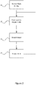
- FIG. 2 shows a flow diagram for controlling the lighting system 10.
- the first step S1 is for the lighting control unit 50 to receive the flash settings. The user then instructs the system to enter a 'wait for trigger mode' in step S2.
- the lighting device 12 is primed so as to be ready to produce a flash.
- the current (or voltage) to the lighting device 12 is ramped up to the required level to generate the flash while the continuous light output is throttled at a constant level to dim the lighting device 12 to compensate for the increased peak current (or voltage).
- step S3 A trigger is then detected at step S3, the lighting control unit 50 then waits for the specified delay period then outputs a flash in step S4. The system then returns to the 'wait for trigger' mode in step S2.
- the user can exit the primed 'wait-for-trigger' mode by pressing a button on the lighting device (or via a wireless device). This sets the lighting device 12 current back to its normal value and puts the lighting device 12 back into normal continuous operation mode.
- the 'priming' of the lighting device 12 in the 'wait for trigger' mode in one example involves increasing the power supplied to the device by throttling the transmission of the power to the lighting device 12 so that the output of the light is the relatively low-level 'continuous' light.
- this throttling is reduced or removed for a short duration so that a higher power is transmitted to the lighting device 12 to emit a 'flash'.
- the power supply 14 of lighting system 10 may comprise overload compensation circuity so that short increases in current draw (during the 'flash') do not damage the components of the system 10.
- the power throttling may take the form of modulating the power supplied to the lighting device 12, controlled by the processor 54 and associated memory 56 controlling a modulation circuit in the output unit 58.
- the modulation is in the form of pulse width modulation.
- Modulation reduces the losses that compared to throttling the power by way of resistive means (for example) as the resistive losses in modulation only occur during the transition state of the switch used, which is negligible when using semiconductor switches such as metal oxide field-effect transistors (MOSFETs) or insulated-gate bipolar transistors IGBTs.
- MOSFETs metal oxide field-effect transistors
- IGBTs insulated-gate bipolar transistors
- analogue dimming of LEDs by resistive means may alter the colour characteristics, meaning that the flash may be a slightly different colour to the continuous 'modelling light'.
- Modulation is well-suited to providing a very short pulse as switching by way of semiconductor switches can accurately produce a 'pulse' of increased power with a controllable delay for a controllable period, for example so that a user can adjust the delay and/or duration of the flash in the order of milliseconds.
- the modulation results in the current and/or the voltage supplied to the lighting device 12 being lowered (stepped-down) when in continuous mode. If the lighting device 12 comprises LEDs, flickering may occur if the voltage is lowered below an activation voltage, so it may be preferable to control the current.
- a current-mode controlled pulse width modulation circuit may be utilised to control the current supplied to the lighting source 12. Such circuitry may be more complex than voltage-mode controlled pulse with modulation circuity, but effectively eliminates 'flickering', and simplifies load sharing.
- a voltage-mode controlled modulation circuit may be used to control the voltage supplied to the lighting source 12. If this produces flickering at a frequency above human perception (e.g. above 200Hz), and/or at a frequency above the frame rate / shutter speed of a camera recording the scene, it can be accepted.
- a frequency above human perception e.g. above 200Hz
- a frequency above the frame rate / shutter speed of a camera recording the scene it can be accepted.
- Example of suitable modulation circuitry include: triode for alternating current (TRIAC) diode (also referred to as a bidirectional triode thyristor), or a Buck converter, under the control of a clock output from processor 54.
- TRIAC alternating current
- a Buck converter under the control of a clock output from processor 54.
- components to rectify an AC signal to DC may be incorporated as necessary.
- triggering a second flash may damage the LED element by keeping it on at a higher output level that would be optimal.
- a second flash trigger i.e. asking the unit to fire
- the lighting device automatically truncates the flash duration to still provide the user with a usable flash, but at the same time preventing damage to the LED lighting element that would otherwise occur.
- This feature is termed 'Adaptive input monitoring' (A.I.M).
- the appropriate duration of a second flash is thus determined in dependence on the time elapsed since a previous flash trigger was received - generally, the closer the two flashes are together, the shorter the duration the second flash will be so as to protect the lighting element.
- a further feature of the lighting control system is the ability to provide a continuous LED light that is also able to flash at a shutter speed faster than the native internal sync speed of a camera.
- Typical flash guns have the problem that the duration of the flash is very short and as such when using a very fast shutter speed a portion of the frame may not be lit (or appearing to have a band of unlit frame). This is particularly problematic when you require faster shutter speeds to effectively capture the action, or for other aesthetic reasons (like requiring a wide aperture).
- the apparatus described herein is adapted to provide a continuous burst of LED light that at a shutter speed faster than the native internal sync speed of a camera - substantially for the duration that the camera's shutter is open - as shown in Figure 3(b) .
- a shutter-synchronised flash is provided that is a brighter continuous light during the entire period the camera shutter is open, effectively enabling a flash at a shutter speed that is faster than the native internal sync speed of the camera.
- This approach is particularly well suited to LED lighting where a constant, controllable light output can be produced - which is not possible when using halogen flash units.
- Typical flash/strobe units work by storing energy into a capacitor, which is then released as one major flash burst. A recycle time is then required to recharge that capacitor in order to provide another burst. This results in critical moments where the flash simply does not fire resulting in under exposed photographs, or completely unusable results. In situations such as weddings photography, that perfect moment may be lost forever whilst waiting for the flash to recharge.
- Modern cameras can now shoot at multiple frames per second and the present system is able to respond to the needs of those modern cameras.
- Existing cameras which rely on capacitors cannot enable a photographer to take advantage of a camera's ability to shoot multiple frames per second whilst using flash.
- the present system provides a continuous LED light that can also flash.
- the LEDs have the advantage that they do not have to store energy in capacitor releasing it in one major event.
- LED systems would run at 20mA nominal current to avoid damage to LEDs that can be caused by running at higher currents.
- the system described herein enables the LEDs to run at multiples over than 20mA (e.g. 4 or 5x) i.e. up to 100mA to produce a 'burst' or flash of light, resulting in a light output significantly greater that the normally derived light output, whilst at the same time avoiding damage that would typically occur by running an LED over its nominal operating current (which refers to continuous current provided to the LED).
- multiple lighting devices 12 may be coupled together, but only a sub-set of them may flash when a trigger is received.
Landscapes
- Physics & Mathematics (AREA)
- General Physics & Mathematics (AREA)
- Engineering & Computer Science (AREA)
- Multimedia (AREA)
- Signal Processing (AREA)
- Studio Devices (AREA)
- Circuit Arrangement For Electric Light Sources In General (AREA)
- Stroboscope Apparatuses (AREA)
Applications Claiming Priority (3)
| Application Number | Priority Date | Filing Date | Title |
|---|---|---|---|
| GB1606658.1A GB2549333A (en) | 2016-04-15 | 2016-04-15 | Lighting device and control thereof |
| GB1705754.8A GB2547811B (en) | 2016-04-15 | 2017-04-10 | Lighting device and control thereof |
| EP17166340.4A EP3232264B1 (en) | 2016-04-15 | 2017-04-12 | Lighting device and control thereof |
Related Parent Applications (1)
| Application Number | Title | Priority Date | Filing Date |
|---|---|---|---|
| EP17166340.4A Division EP3232264B1 (en) | 2016-04-15 | 2017-04-12 | Lighting device and control thereof |
Publications (1)
| Publication Number | Publication Date |
|---|---|
| EP3995889A1 true EP3995889A1 (en) | 2022-05-11 |
Family
ID=58744721
Family Applications (2)
| Application Number | Title | Priority Date | Filing Date |
|---|---|---|---|
| EP21211524.0A Withdrawn EP3995889A1 (en) | 2016-04-15 | 2017-04-12 | Lighting device and control thereof |
| EP17166340.4A Active EP3232264B1 (en) | 2016-04-15 | 2017-04-12 | Lighting device and control thereof |
Family Applications After (1)
| Application Number | Title | Priority Date | Filing Date |
|---|---|---|---|
| EP17166340.4A Active EP3232264B1 (en) | 2016-04-15 | 2017-04-12 | Lighting device and control thereof |
Country Status (4)
| Country | Link |
|---|---|
| US (3) | US10606150B2 (enExample) |
| EP (2) | EP3995889A1 (enExample) |
| JP (1) | JP6961168B2 (enExample) |
| GB (2) | GB2549333A (enExample) |
Cited By (1)
| Publication number | Priority date | Publication date | Assignee | Title |
|---|---|---|---|---|
| US20240064413A1 (en) * | 2022-08-22 | 2024-02-22 | Meta Platforms Technologies, Llc | Comfortable multiplexed lighting for modeling relightable avatars |
Families Citing this family (9)
| Publication number | Priority date | Publication date | Assignee | Title |
|---|---|---|---|---|
| GB2520087A (en) | 2013-11-11 | 2015-05-13 | Vectair Systems Ltd | Fragrance Dispenser |
| GB2549333A (en) * | 2016-04-15 | 2017-10-18 | Rotolight Ltd | Lighting device and control thereof |
| US11728668B2 (en) * | 2017-06-02 | 2023-08-15 | Apple Inc. | Electronic device with battery capability modeling |
| DE102017212313A1 (de) * | 2017-07-19 | 2019-01-24 | BSH Hausgeräte GmbH | Haushaltsgeschirrspülmaschine und Verfahren zum Betreiben einer Haushaltsgeschirrspülmaschine |
| KR102008267B1 (ko) * | 2017-12-12 | 2019-08-07 | 엘지전자 주식회사 | 라이팅 장치 및 이를 포함하는 공연 시스템 |
| CN108521701B (zh) * | 2018-03-30 | 2024-05-10 | 宁波格立光电科技有限公司 | 调光控制器及调光方法 |
| JP7141910B2 (ja) * | 2018-10-26 | 2022-09-26 | シーシーエス株式会社 | Oled駆動装置およびoled駆動方法ならびにoled駆動システム |
| JP7278057B2 (ja) * | 2018-11-02 | 2023-05-19 | シャープ株式会社 | 照明装置 |
| CN112882318B (zh) * | 2021-02-10 | 2025-10-03 | 深圳市影友摄影器材有限公司 | 闪光灯色温控制电路及控制方法、闪光灯设备 |
Citations (3)
| Publication number | Priority date | Publication date | Assignee | Title |
|---|---|---|---|---|
| US20070189754A1 (en) * | 2004-02-12 | 2007-08-16 | Hiroyuki Iwasaki | Camera system |
| US20110119409A1 (en) * | 2009-11-18 | 2011-05-19 | Leap Devices, LLC. | Device, system, and method to couple a personal digital assistant with a camera |
| JP2014232163A (ja) * | 2013-05-28 | 2014-12-11 | キヤノン株式会社 | 照明装置、撮像装置、発光制御方法並びにプログラム |
Family Cites Families (24)
| Publication number | Priority date | Publication date | Assignee | Title |
|---|---|---|---|---|
| JP3120903B2 (ja) * | 1992-07-29 | 2000-12-25 | 旭光学工業株式会社 | カメラおよびスレーブ機能を備えたストロボ装置 |
| JP2000019615A (ja) * | 1998-06-30 | 2000-01-21 | Kyocera Corp | 撮影タイミング表示装置 |
| US6407512B1 (en) * | 1999-11-19 | 2002-06-18 | Fuji Photo Film Co., Ltd. | Flashing device of an automatic light-regulation type |
| JP4288553B2 (ja) * | 2000-07-25 | 2009-07-01 | 富士フイルム株式会社 | カメラのストロボ装置 |
| JP4040358B2 (ja) * | 2002-03-15 | 2008-01-30 | シャープ株式会社 | 撮影機能を有した携帯電話機 |
| JP2005130111A (ja) * | 2003-10-22 | 2005-05-19 | Nec Corp | カメラ付き携帯電話機 |
| WO2008036978A2 (en) * | 2006-09-22 | 2008-03-27 | High Lighting Llc | Lighting systems |
| WO2008042402A2 (en) * | 2006-10-02 | 2008-04-10 | Heffelfinger David M | Vehicle testing lamp apparatus, system, and method |
| WO2008078136A1 (en) * | 2006-12-27 | 2008-07-03 | Nokia Corporation | An illumination apparatus for an electronic device |
| CA2752169A1 (en) * | 2009-02-12 | 2010-08-19 | Lab Partners Associates, Inc. | Early photographic synchronization system and method |
| US8718461B2 (en) * | 2009-02-12 | 2014-05-06 | Lab Partners Associates, Inc. | Photographic synchronization optimization system and method |
| CN101604111B (zh) * | 2009-06-15 | 2013-01-02 | 张一鸣 | 一种防逆光拍摄的方法和装置 |
| US20120044374A1 (en) | 2010-02-19 | 2012-02-23 | Pohlert Rudy G | Photography led lighting and effects generation system |
| ES2640955T3 (es) * | 2010-03-09 | 2017-11-07 | Perceptimed, Inc. | Verificación y dispensación de medicación |
| GB2482562A (en) * | 2010-08-06 | 2012-02-08 | Morten Hjerde | Light control device |
| US9338330B2 (en) * | 2011-09-23 | 2016-05-10 | Reflex Technologies, Llc | Method and apparatus for continuous motion film scanning |
| JP5866962B2 (ja) * | 2011-10-21 | 2016-02-24 | 株式会社ニコン | 照明装置 |
| JP6161262B2 (ja) * | 2012-11-19 | 2017-07-12 | 株式会社ミツトヨ | 画像測定機のled照明方法及び装置 |
| CN104301475B (zh) * | 2013-07-17 | 2018-01-05 | 联芯科技有限公司 | 具有闪光灯和手电筒功能的移动终端 |
| US9690169B2 (en) * | 2013-11-04 | 2017-06-27 | Lab Partners Associates, Inc. | Photographic lighting system and method |
| KR101517330B1 (ko) * | 2014-04-25 | 2015-05-04 | 송창환 | 연성기판을 이용한 섬광 및 지속광 led 조명 |
| WO2016076777A1 (en) * | 2014-11-14 | 2016-05-19 | Profoto Ab | A flash generator for a flash tube |
| US10704745B2 (en) * | 2015-10-13 | 2020-07-07 | Lume Cube, Inc. | Mobile light source |
| GB2549333A (en) * | 2016-04-15 | 2017-10-18 | Rotolight Ltd | Lighting device and control thereof |
-
2016
- 2016-04-15 GB GB1606658.1A patent/GB2549333A/en not_active Withdrawn
-
2017
- 2017-04-10 GB GB1705754.8A patent/GB2547811B/en not_active Expired - Fee Related
- 2017-04-11 JP JP2017078504A patent/JP6961168B2/ja active Active
- 2017-04-12 US US15/485,239 patent/US10606150B2/en active Active
- 2017-04-12 EP EP21211524.0A patent/EP3995889A1/en not_active Withdrawn
- 2017-04-12 EP EP17166340.4A patent/EP3232264B1/en active Active
-
2020
- 2020-03-10 US US16/813,750 patent/US11079658B2/en not_active Expired - Fee Related
-
2021
- 2021-07-12 US US17/372,539 patent/US20210333691A1/en not_active Abandoned
Patent Citations (3)
| Publication number | Priority date | Publication date | Assignee | Title |
|---|---|---|---|---|
| US20070189754A1 (en) * | 2004-02-12 | 2007-08-16 | Hiroyuki Iwasaki | Camera system |
| US20110119409A1 (en) * | 2009-11-18 | 2011-05-19 | Leap Devices, LLC. | Device, system, and method to couple a personal digital assistant with a camera |
| JP2014232163A (ja) * | 2013-05-28 | 2014-12-11 | キヤノン株式会社 | 照明装置、撮像装置、発光制御方法並びにプログラム |
Cited By (1)
| Publication number | Priority date | Publication date | Assignee | Title |
|---|---|---|---|---|
| US20240064413A1 (en) * | 2022-08-22 | 2024-02-22 | Meta Platforms Technologies, Llc | Comfortable multiplexed lighting for modeling relightable avatars |
Also Published As
| Publication number | Publication date |
|---|---|
| GB201705754D0 (en) | 2017-05-24 |
| US10606150B2 (en) | 2020-03-31 |
| US20200209716A1 (en) | 2020-07-02 |
| JP6961168B2 (ja) | 2021-11-05 |
| US20180004069A1 (en) | 2018-01-04 |
| EP3232264B1 (en) | 2021-12-01 |
| US20210333691A1 (en) | 2021-10-28 |
| GB2547811A (en) | 2017-08-30 |
| GB2547811B (en) | 2020-11-25 |
| JP2017201619A (ja) | 2017-11-09 |
| GB2549333A (en) | 2017-10-18 |
| EP3232264A1 (en) | 2017-10-18 |
| US11079658B2 (en) | 2021-08-03 |
Similar Documents
| Publication | Publication Date | Title |
|---|---|---|
| US11079658B2 (en) | Lighting system and control thereof | |
| US10667360B2 (en) | Artificial light color mixing process | |
| US11096255B2 (en) | Ambient light sensing lighting system | |
| CN101025544A (zh) | 照相机的闪光灯装置及电子照相机 | |
| WO2018124439A1 (ko) | 피사체와 조명장치 간의 거리에 연동하여 조명장치의 출력을 조절하는 조명용 자동제어장치 | |
| CN113974526A (zh) | 一种自动调光频闪的光源装置及内窥镜 | |
| US11096260B2 (en) | Ambient light sensing lighting strobe system | |
| KR101014622B1 (ko) | 사진촬영용 엘이디 조명장치 및 그 제어방법 | |
| US20200041082A1 (en) | Adaptive Ambiance Lighting | |
| JP2010102208A (ja) | 撮影用補助光源装置 | |
| WO2015051592A1 (zh) | 多灯具的控制方法 | |
| NL2021044B1 (en) | LED driver and method of operating a camera | |
| US11864293B2 (en) | Hard and soft light module with ambient light sensing | |
| WO2016074645A1 (zh) | 数字影棚摄影灯光系统 | |
| CN108064099B (zh) | 智能照明控制系统、控制方法及智能照明系统 | |
| CN108541110B (zh) | 一种自动调节式大功率补光装置及其补光方法 | |
| CN103179742B (zh) | 同步调光方法 | |
| JP2013200322A (ja) | Ledフラッシュ光源の発光制御方法と、ledフラッシュ光源装置 | |
| US20220187684A1 (en) | External light source for mobile devices | |
| CN119071643B (zh) | 光源控制方法、机器视觉光源控制器及工业相机 | |
| JP2014077962A (ja) | ストロボ装置 | |
| JPH04136922A (ja) | ストロボ内蔵カメラ | |
| JP2006227154A (ja) | 写真撮影用照明装置 | |
| TWM473535U (zh) | 微白光照明設備改良結構 | |
| TWM473534U (zh) | 微白光照明設備 |
Legal Events
| Date | Code | Title | Description |
|---|---|---|---|
| PUAI | Public reference made under article 153(3) epc to a published international application that has entered the european phase |
Free format text: ORIGINAL CODE: 0009012 |
|
| STAA | Information on the status of an ep patent application or granted ep patent |
Free format text: STATUS: THE APPLICATION HAS BEEN PUBLISHED |
|
| AC | Divisional application: reference to earlier application |
Ref document number: 3232264 Country of ref document: EP Kind code of ref document: P |
|
| AK | Designated contracting states |
Kind code of ref document: A1 Designated state(s): AL AT BE BG CH CY CZ DE DK EE ES FI FR GB GR HR HU IE IS IT LI LT LU LV MC MK MT NL NO PL PT RO RS SE SI SK SM TR |
|
| RAP1 | Party data changed (applicant data changed or rights of an application transferred) |
Owner name: ROTOLIGHT TECHNOLOGIES LIMITED |
|
| STAA | Information on the status of an ep patent application or granted ep patent |
Free format text: STATUS: REQUEST FOR EXAMINATION WAS MADE |
|
| 17P | Request for examination filed |
Effective date: 20230216 |
|
| RBV | Designated contracting states (corrected) |
Designated state(s): AL AT BE BG CH CY CZ DE DK EE ES FI FR GB GR HR HU IE IS IT LI LT LU LV MC MK MT NL NO PL PT RO RS SE SI SK SM TR |
|
| STAA | Information on the status of an ep patent application or granted ep patent |
Free format text: STATUS: EXAMINATION IS IN PROGRESS |
|
| 17Q | First examination report despatched |
Effective date: 20241115 |
|
| STAA | Information on the status of an ep patent application or granted ep patent |
Free format text: STATUS: THE APPLICATION IS DEEMED TO BE WITHDRAWN |
|
| 18D | Application deemed to be withdrawn |
Effective date: 20250318 |