EP3989346A1 - Anordnungsartiges batteriepack für ess - Google Patents
Anordnungsartiges batteriepack für ess Download PDFInfo
- Publication number
- EP3989346A1 EP3989346A1 EP21822072.1A EP21822072A EP3989346A1 EP 3989346 A1 EP3989346 A1 EP 3989346A1 EP 21822072 A EP21822072 A EP 21822072A EP 3989346 A1 EP3989346 A1 EP 3989346A1
- Authority
- EP
- European Patent Office
- Prior art keywords
- lead
- battery cell
- battery
- cartridge
- battery pack
- Prior art date
- Legal status (The legal status is an assumption and is not a legal conclusion. Google has not performed a legal analysis and makes no representation as to the accuracy of the status listed.)
- Pending
Links
Images


Classifications
-
- H—ELECTRICITY
- H01—ELECTRIC ELEMENTS
- H01M—PROCESSES OR MEANS, e.g. BATTERIES, FOR THE DIRECT CONVERSION OF CHEMICAL ENERGY INTO ELECTRICAL ENERGY
- H01M50/00—Constructional details or processes of manufacture of the non-active parts of electrochemical cells other than fuel cells, e.g. hybrid cells
- H01M50/20—Mountings; Secondary casings or frames; Racks, modules or packs; Suspension devices; Shock absorbers; Transport or carrying devices; Holders
-
- H—ELECTRICITY
- H01—ELECTRIC ELEMENTS
- H01M—PROCESSES OR MEANS, e.g. BATTERIES, FOR THE DIRECT CONVERSION OF CHEMICAL ENERGY INTO ELECTRICAL ENERGY
- H01M50/00—Constructional details or processes of manufacture of the non-active parts of electrochemical cells other than fuel cells, e.g. hybrid cells
- H01M50/50—Current conducting connections for cells or batteries
- H01M50/502—Interconnectors for connecting terminals of adjacent batteries; Interconnectors for connecting cells outside a battery casing
-
- H—ELECTRICITY
- H01—ELECTRIC ELEMENTS
- H01M—PROCESSES OR MEANS, e.g. BATTERIES, FOR THE DIRECT CONVERSION OF CHEMICAL ENERGY INTO ELECTRICAL ENERGY
- H01M50/00—Constructional details or processes of manufacture of the non-active parts of electrochemical cells other than fuel cells, e.g. hybrid cells
- H01M50/50—Current conducting connections for cells or batteries
- H01M50/531—Electrode connections inside a battery casing
- H01M50/536—Electrode connections inside a battery casing characterised by the method of fixing the leads to the electrodes, e.g. by welding
-
- H—ELECTRICITY
- H01—ELECTRIC ELEMENTS
- H01M—PROCESSES OR MEANS, e.g. BATTERIES, FOR THE DIRECT CONVERSION OF CHEMICAL ENERGY INTO ELECTRICAL ENERGY
- H01M50/00—Constructional details or processes of manufacture of the non-active parts of electrochemical cells other than fuel cells, e.g. hybrid cells
- H01M50/10—Primary casings; Jackets or wrappings
- H01M50/116—Primary casings; Jackets or wrappings characterised by the material
- H01M50/124—Primary casings; Jackets or wrappings characterised by the material having a layered structure
-
- H—ELECTRICITY
- H01—ELECTRIC ELEMENTS
- H01M—PROCESSES OR MEANS, e.g. BATTERIES, FOR THE DIRECT CONVERSION OF CHEMICAL ENERGY INTO ELECTRICAL ENERGY
- H01M50/00—Constructional details or processes of manufacture of the non-active parts of electrochemical cells other than fuel cells, e.g. hybrid cells
- H01M50/20—Mountings; Secondary casings or frames; Racks, modules or packs; Suspension devices; Shock absorbers; Transport or carrying devices; Holders
- H01M50/204—Racks, modules or packs for multiple batteries or multiple cells
- H01M50/207—Racks, modules or packs for multiple batteries or multiple cells characterised by their shape
- H01M50/211—Racks, modules or packs for multiple batteries or multiple cells characterised by their shape adapted for pouch cells
-
- H—ELECTRICITY
- H01—ELECTRIC ELEMENTS
- H01M—PROCESSES OR MEANS, e.g. BATTERIES, FOR THE DIRECT CONVERSION OF CHEMICAL ENERGY INTO ELECTRICAL ENERGY
- H01M50/00—Constructional details or processes of manufacture of the non-active parts of electrochemical cells other than fuel cells, e.g. hybrid cells
- H01M50/20—Mountings; Secondary casings or frames; Racks, modules or packs; Suspension devices; Shock absorbers; Transport or carrying devices; Holders
- H01M50/258—Modular batteries; Casings provided with means for assembling
-
- H—ELECTRICITY
- H01—ELECTRIC ELEMENTS
- H01M—PROCESSES OR MEANS, e.g. BATTERIES, FOR THE DIRECT CONVERSION OF CHEMICAL ENERGY INTO ELECTRICAL ENERGY
- H01M50/00—Constructional details or processes of manufacture of the non-active parts of electrochemical cells other than fuel cells, e.g. hybrid cells
- H01M50/50—Current conducting connections for cells or batteries
- H01M50/502—Interconnectors for connecting terminals of adjacent batteries; Interconnectors for connecting cells outside a battery casing
- H01M50/509—Interconnectors for connecting terminals of adjacent batteries; Interconnectors for connecting cells outside a battery casing characterised by the type of connection, e.g. mixed connections
- H01M50/51—Connection only in series
-
- H—ELECTRICITY
- H01—ELECTRIC ELEMENTS
- H01M—PROCESSES OR MEANS, e.g. BATTERIES, FOR THE DIRECT CONVERSION OF CHEMICAL ENERGY INTO ELECTRICAL ENERGY
- H01M50/00—Constructional details or processes of manufacture of the non-active parts of electrochemical cells other than fuel cells, e.g. hybrid cells
- H01M50/50—Current conducting connections for cells or batteries
- H01M50/502—Interconnectors for connecting terminals of adjacent batteries; Interconnectors for connecting cells outside a battery casing
- H01M50/514—Methods for interconnecting adjacent batteries or cells
- H01M50/517—Methods for interconnecting adjacent batteries or cells by fixing means, e.g. screws, rivets or bolts
-
- H—ELECTRICITY
- H01—ELECTRIC ELEMENTS
- H01M—PROCESSES OR MEANS, e.g. BATTERIES, FOR THE DIRECT CONVERSION OF CHEMICAL ENERGY INTO ELECTRICAL ENERGY
- H01M2220/00—Batteries for particular applications
- H01M2220/10—Batteries in stationary systems, e.g. emergency power source in plant
-
- Y—GENERAL TAGGING OF NEW TECHNOLOGICAL DEVELOPMENTS; GENERAL TAGGING OF CROSS-SECTIONAL TECHNOLOGIES SPANNING OVER SEVERAL SECTIONS OF THE IPC; TECHNICAL SUBJECTS COVERED BY FORMER USPC CROSS-REFERENCE ART COLLECTIONS [XRACs] AND DIGESTS
- Y02—TECHNOLOGIES OR APPLICATIONS FOR MITIGATION OR ADAPTATION AGAINST CLIMATE CHANGE
- Y02E—REDUCTION OF GREENHOUSE GAS [GHG] EMISSIONS, RELATED TO ENERGY GENERATION, TRANSMISSION OR DISTRIBUTION
- Y02E60/00—Enabling technologies; Technologies with a potential or indirect contribution to GHG emissions mitigation
- Y02E60/10—Energy storage using batteries
Definitions
- the present disclosure relates to a battery pack, and more particularly, to a battery pack for an Energy Storage System (ESS).
- ESS Energy Storage System
- Lithium secondary batteries which can be repeatedly recharged as an alternative to fossil energy.
- Lithium secondary batteries have been primarily used in traditional hand-held devices such as mobile phones, video cameras and electric tools. Recently, there is a growing tendency of the range of applications of lithium secondary batteries to electric vehicles (EV, HEV, PHEV), uninterruptible power supply systems (UPSs) and energy storage systems (ESSs).
- EV electric vehicles
- HEV high-voltage
- PHEV uninterruptible power supply systems
- ESSs energy storage systems
- a battery module or battery pack is used in which a plurality of battery cells themselves or mounted in a cartridge is stacked to form a dense structure, and electrically connected to each other.
- the ESS refers to a system which is supplied with external power from an external power source, for example, a power generation plant, stores it, and transmits the power to a desired location at a necessary time.
- an external power source for example, a power generation plant
- power from renewable energy sources such as solar power and wind power may be stored, and power may be supplied from external power sources at low times at which electricity rates are low and stored, and the stored power may be supplied at times when power consumption is high, thereby contributing to the high efficiency of power management from the position of power providers and low electricity costs from the position of customers.
- a battery pack necessary for a home ESS may be manufactured by stacking a plurality of battery cells to form a dense structure, and electrically connecting them. Since the electrical connection is established by welding the leads of the battery cells, the battery module or battery pack in the form of a welded product is provided to customers. Problems may occur during the use of the battery pack, and the most common problem is deformation of the battery module caused by swelling of a specific battery cell and a voltage drop of the specific battery cell, and these problems are those occurring in the specific battery cell, not those occurring over the entire battery module.
- the present disclosure is directed to providing a battery pack for a home energy storage system (ESS) which is so easy to separate and install a battery cell that a customer can replace the battery cell in person.
- ESS home energy storage system
- a battery pack includes a casing, at least two battery cells, and a system including a cartridge in which the battery cell is received and a lead jig, wherein the cartridge is configured to be opened and closed to attach/detach the battery cell, and the lead jig is configured to be mounted/demounted on/from a lead of the battery cell, and when the battery cell is received in the cartridge and stacked in a thicknesswise direction and the lead jig is mounted on the lead of the battery cell, an electrical connection is established between the battery cells without welding the leads of the battery cells.
- the battery cell may be a pouch type secondary battery of a flat shape including a laminated film for hermetic seal and the lead extending in two directions.
- the lead jig may be provided on the two directions in which the leads of the battery cell extend.
- the casing may include a case configured to receive the battery cell to stack the battery cell in the thicknesswise direction and having an opening formed in at least one end.
- the cartridge may be press-fit into the casing.
- the cartridge may include a pair of frames to support edges of the battery cell while exposing the lead of the battery cell, and snap buttons disposed on opposing sides between the pair of frames.
- the lead jig may include a pair of conductive plates where the lead of the battery cell is inserted in between, and an adjustment member connected to reduce a distance between the pair of conductive plates so that the conductive plates compress the lead, or increase the distance between the conductive plates to separate the conductive plates from the lead.
- the adjustment member may be a lever member which works with movement of one of the pair of conductive plates closer to and away from the lead.
- the lead jig may further include a connecting bar to connect in series the lead of any one battery cell to the lead of the adjacent battery cell in the thicknesswise direction.
- the cartridge in which the battery cells are received and the configuration for connection between the leads can be assembled/disassembled or attached/detached, it is possible to easily separate and install the battery cell of the battery pack for a home energy storage system (ESS) by mounting/demounting the jig and the cartridge. Accordingly, it is possible to reduce the burden for replacement of a specific battery cell when a problem occurs in the specific battery cell and eliminate the need to replace the entire battery module or battery pack due to the problem occurred in the specific battery cell.
- ESS home energy storage system
- the present disclosure there is no need to weld the leads of the battery cells beforehand, i.e., before provided to customers, thereby achieving cost savings. It is possible to reduce damage to the casing which may occur during delivery of finished products. Since the battery cell, the casing and the system may be separately delivered, it is possible to achieve flexibility in products supply.
- the present disclosure manufactures an assemble type battery pack.
- the assemble type refers to a configuration in which individual parts can be assembled and disassembled depending on the purpose.
- the present disclosure proposes to provide customers with each of a casing, a system and a battery cell as disassembled, not welded together like the conventional battery module or battery pack, that is, each modular component, and assembling them at the destination.
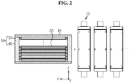
- FIG. 1 is a block diagram conceptually showing the battery pack according to an embodiment of the present disclosure. Additionally, FIG. 2 is a schematic diagram showing a simplest example of the battery pack of FIG. 1 .
- the battery pack 100 is a modular battery pack, and includes a casing 10, at least two battery cells 20 and a system 50.
- the system 50 includes a cartridge 30 in which the battery cells 20 are received and a lead jig 40. All the components may have an electric shock prevention function. Each component is provided to a customer as separated as shown in FIG. 1 , and may be assembled into the battery pack 100 at the destination.
- the system 50 may be mounted in the casing 10.
- the system 50 mounted in the casing 10 and the battery cell 20 may be separately provided to the customer as shown in FIG. 2 , and the customer only has to combine the battery cell 20 with the cartridge 30 and the lead jig 40 at the destination. That is, since the system 50 has been already completed, to use, just combine the battery cell 20 with the cartridge 30 and the lead jig 40.
- the cartridge 30 is used to receive the battery cell 20 therein and stack in the thicknesswise direction within the casing 10.
- the cartridge 30 is configured to be opened and closed to attach/detach the battery cell 20.
- the lead jig 40 is configured to be mounted/demounted on/from the lead of the battery cell 20.
- the lead jig 40 is mounted on the lead of the battery cell 20.
- the customer puts the battery cell 20 in the cartridge 30 and places in the lead jig 40.
- the customer may mount the system 50 in the casing 10, put the battery cell 20 in the cartridge 30 and place in the lead jig 40.
- the customer may put the battery cell 20 in the cartridge 30 and stack, then place in the lead jig 40, and put both the battery cell 20 and the system 50 in the casing 10.
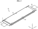
- FIG. 3 is a diagram showing the structure of the battery cell 20 that may be included in the battery pack of the present disclosure.
- the battery cell 20 may be a pouch type secondary battery of a flat shape including a laminated film 22 for a hermetic seal and the lead 24 extending in two directions.
- the pouch type secondary battery may include an electrode assembly and an electrolyte solution in the laminated film 22.
- the electrode assembly may include at least one positive electrode plate and at least one negative electrode plate with a separator interposed between. More specifically, the electrode assembly may be divided into a roll type electrode assembly in which one positive electrode plate and one negative electrode plate are rolled together with a separator, and a stack type electrode assembly in which a plurality of positive electrode plates and a plurality of negative electrode plates are stacked in an alternating manner with a separator interposed between.
- the laminated film 22 may include an outer insulating layer, a metal layer and an inner adhesive layer.
- the laminated film 22 may receive the electrode assembly therein.
- the electrode assembly is interposed between two laminated films 22, and a sealing region S is formed by welding along the periphery of the electrode assembly with the inner adhesive layers of the laminated films 22 in contact with each other to seal an internal space in which the electrode assembly is received.
- the lead 24 connected to the electrode assembly may extend leftward and rightward from the battery cell 20.
- a part of the sealing region S where the lead 24 does not extend may be wing-folded, for example, folded in the thicknesswise direction of the battery cell 20 and finished with a tape 26.
- the battery cell 20 when the thicknesswise direction of the battery cell 20 is referred to as a Z-axis direction, the battery cell 20 has a flat shape such that a surface perpendicular to the Z-axis direction has a widest area.
- a direction in which the lead 24 extends from the battery cell 20 is referred to as an X-axis direction
- the sealing region S placed in a Y-axis direction perpendicular to the X-axis direction is wing-folded.
- One lead 24 is positive and the other is negative.
- the battery cell 20 is formed in a rectangular shape having two long sides and two short sides along the periphery, and the two short sides are placed perpendicular to the X axis in the X-axis direction and the lead 24 extends to form a terrace.
- the two long sides are placed perpendicular to the Y axis in the Y-axis direction.
- the battery pack 100 may include various types of battery cells known at the time of filing the patent application.
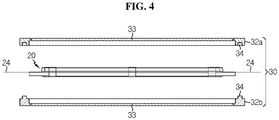
- FIG. 4 is an exploded cross-sectional view of the cartridge that may be included in the battery pack of the present disclosure.
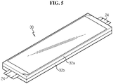
- FIG. 5 is an assembled perspective view of the cartridge and the battery cell.
- the cartridge 30 holds the battery cell 20 to prevent the battery cell 20 from moving.
- the cartridge 30 is configured to be opened and closed to attach/detach the battery cell 20.
- the cartridge 30 includes a pair of frames 32a, 32b to support the edges of the battery cell 20 while exposing the lead 24 of the battery cell 20, and snap buttons 34 may be formed on opposing sides between the pair of frames 32a, 32b.
- the pair of frames 32a, 32b when engaged, may be approximately symmetrical, and may be a frame of a rectangular ring shape with the hollow center.
- the four edges of the pair of frames 32a, 32b are disposed on the periphery of the battery cell 20, and the battery cell 20 may be received in the internal space of the pair of frames 32a, 32b.
- a heat sink 33 may be further included on the inner side of the pair of frames 32a, 32b.
- the cartridge 30 is configured to be opened and closed to attach/detach the battery cell 20.
- the cartridge 30 may stably support the battery cell 20.
- the snap buttons 34 are disengaged, the pair of frames 32a, 32b may be separated, from which the battery cell 20 may be taken out.
- a hook coupling structure may be formed by engaging/disengaging a hook attached to one frame with/from a hook stop formed in the other frame. The cartridge 30 and the battery cell 20 may be assembled/disassembled to maximize the user convenience.
- the casing 10 is configured to receive and store the battery cell 20 therein to protect the battery cell 20. Additionally, the casing 10 forms the shape of the entire battery pack 100.
- the casing 10 may have a receiving space for receiving the battery cell 20 by the unit of the cartridge 30.
- the inside and outside of the casing 10 need the insulating and flame retardant functions, and the casing 10 may have various types and shapes. Due to the limited space for installation in home, it is necessary to make the casing 10 and the entire system compact.
- FIG. 6 shows an example of the casing 10 that may be included in the battery pack 100 of the present disclosure.
- the casing 10 may include a case 12 in which the battery cell 20 is received to stack in the thicknesswise direction and having an opening O formed in at least one end.
- the opening O may be formed at various locations, for example, top, bottom or side of the case 12. After all the battery cells 20 are received in the case 12, the opening O may be closed with a cover 14. The cover 14 is opened and closed.
- this embodiment shows that the opening O is disposed on the side of the case 12 and covered with the cover 14 to form an approximately rectangular box shape, the present disclosure is not limited to the shape of the casing 10.
- the cartridge 30 may be press-fit into the casing 10.
- the case 12 may further include an auxiliary configuration for receiving the cartridge 30, for example, a groove structure into which the cartridge 30 is slidably inserted through the cartridge 30 the opening O or a protrusion such as a rack on which each cartridge 30 is placed.
- each individual cartridge 30 may be pushed into place and received in the casing 10, and it is possible to support the battery cell 20 more stably.
- the battery pack 100 including the casing 10 may be manufactured to hold the battery cell 20 by the unit of the cartridge 30.
- the case 12 itself may be assembled.
- the case 12 may include a top plate 12a to cover the top of the battery cell 20 received in the topmost cartridge 30 in the Z-axis direction, a bottom plate 12b placed opposite the top plate 12a to cover the bottom of the battery cell 20 received in the bottommost cartridge 30, and a pair of side plates 12c connected to the top plate 12a and the bottom plate 12b and placed outside of the short sides of the battery cells 20.
- a rectangular tubular shape having two open sides in the Y-axis direction may be formed.
- the case 12 may further include a rear plate 12d that vertically meets the top plate 12a, the bottom plate 12b and the side plates 12c to close one of the open sides.
- the battery pack 100 for use in home ESS may be formed in a wall-hanging shape for user convenience and space utilization, and installed on the indoor or outdoor wall or column.
- a bracket for wall-mounting use may be added according to the properties of the corresponding product. Accordingly, the casing 10 may be fixed using the added bracket or a support such as a rack with the rear plate 12d placed facing the wall.
- the user may remove the cover 14 disposed on the front side to see the inner part of the case 12 in a straightforward manner.
- the cartridge 30 or the battery cell 20 may inserted or removed through the opening O.
- any other example of the casing 10 is possible.
- the top plate 12a, the bottom plate 12b, the side plates 12c and the rear plate 12d may be connected in contact with one another by bonding or bolting or using a hinge structure.
- any one may have a press-fit protrusion and the other may have a press-fit groove
- the top plate 12a, the bottom plate 12b, the side plates 12c and the rear plate 12d may be assembled by press-fitting.
- each of the press-fit groove and the press-fit protrusion may be continuously formed along the vertical edges of the top plate 12a, the bottom plate 12b, the side plates 12c, and the rear plate 12d.
- a fixing member may be included between the cover 14 and the case 12 to fix the cover 14 to the case 12.
- FIG. 7 is a schematic diagram of the lead jig 40 that may be included in the battery pack 100 of the present disclosure.
- the lead jig 40 is configured to be mounted/demounted on/from the lead 24 of the battery cell 20.
- the lead jig 40 may include a pair of conductive plates 41a, 41b and an adjustment member 43. Since the battery cell 20 has the bidirectional lead 24, the lead jig 40 may be provided in the two directions in which the lead 24 of the battery cell 20 extends.
- a unit including the pair of conductive plates 41a, 41b and the adjustment member 43 may be provided corresponding to the lead 24 of the battery cell 20 for each battery cell 20.
- the casing 10 may further include an auxiliary configuration to simply receive the units, fix after receiving, or install earlier than the cartridge 30.
- the lead 24 of the battery cell 20 may be inserted in between the pair of conductive plates 41a, 41b.
- the pair of conductive plates 41a, 41b are provided with an area that is similar to or larger than the lead 24.
- the pair of conductive plates 41a, 41b further include a hole, through which a connection member such as a fastener or a screw is further provided, to allow the pair of conductive plates 41a, 41b to move in the Z-axis direction and prevent them from sliding or moving in the X-axis direction or Y-axis direction.
- the adjustment member 43 is connected to the pair of conductive plates 41a, 41b to adjust the distance between the pair of conductive plates 41a, 41b, especially in the Z-axis direction.
- the adjustment member 43 may reduce the distance between the conductive plates 41a, 41b to compress the lead 24 inserted in between the pair of conductive plates 41a, 41b. Additionally, the adjustment member 43 may increase the distance between the conductive plates 41a, 41b to separate the conductive plates 41a, 41b from the lead 24.
- the distance between the pair of conductive plates 41a, 41b may be adjusted by allowing one or both of the conductive plates 41a, 41b to move in the Z-axis direction.
- the system 50 is configured such that when the battery cell 20 is received in the cartridge 30 and stacked in the thicknesswise direction and the lead jig 40 is mounted on the lead 24 of the battery cell 20, electrical connection between the battery cells 20 is established without welding the leads 24 of the battery cells 20.
- the lead jig 40 may further include a connecting bar 44 to connect in series the lead 24 of any one battery cell 20 to the lead 24 of the other adjacent battery cell 20 in the thicknesswise direction, that is, the Z-axis direction.
- a series connection may be established without a member such as a busbar through the connection between the two leads 24 stacked on top of each other in the thicknesswise direction on the side of the battery cells 20.
- the battery cell 20 may be received in the cartridge 30 and stacked in the thicknesswise direction, and the lead jig 40 may be mounted on the lead 24 of the battery cell 20 to complete the battery module, and then received in the casing 10.
- the lead jig 40 may be installed in the casing 10
- the cartridge 30 may be stacked in the casing 10
- the lead 24 may be compressed through the lead jig 40.
- the lead jig 40 may be installed in the casing 10, and each time the cartridge 30 is received in the casing 10, the lead 24 may be compressed through the lead jig 40.
- the casing 10 may further include the auxiliary configuration to simply receive the lead jig 40, fix after receiving, or install earlier than the cartridge 30.
- the lead jig 40 may be installed in the casing 10, and the cartridge 30 may be inserted into the case 12 along the Y-axis direction like putting books on a bookshelf and assembled along the Z-axis direction, or to the contrary, removed and separated one by one.
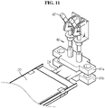
- FIGS. 8 to 11 are diagrams detailing an embodiment of the lead jig 40, and in particular, FIGS. 8 and 9 are side views illustrating a method of use, and FIGS. 10 and 11 are perspective views illustrating a method of use.
- FIGS. 8 to 11 show an example of connecting the battery cell 20 for illustration.
- the adjustment member 43 of the lead jig 40 is a lever member 45.
- the lever member 45 works with the movement of one of the pair of conductive plates 41a, 41b, i.e., the upper conductive plate 41a closer to and away from the lead 24.
- FIG. 8 is a side view showing the connection of the lead 24 of the battery cell 20 using the lever member 45
- FIG. 9 is a side view showing the release of connection of the lead 24 of the battery cell 20 using the lever member 45.
- FIG. 10 is a perspective view showing the connection of the lead 24 of the battery cell 20 using the lever member 45
- FIG. 11 is a perspective view showing the release of connection of the lead 24 of the battery cell 20 using the lever member 45.
- the lever member 45 includes a drive 46 to drive the upper conductive plate 41a to make a vertical motion and a lever 47 to vertically manipulate the drive 46, and when the lever 47 is lowered, the drive 46 is lowered and the upper conductive plate 41a connected thereto moves closer to the lead 24, and when the lever 47 is raised, the drive 46 is raised and the upper conductive plate 41a connected thereto moves away from the lead 24.
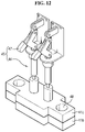
- FIGS. 12 and 13 are perspective views illustrating an embodiment of the lead jig for connection of the battery cell and release of connection.
- FIG. 12 is a perspective view showing the connection of the lead of the battery cell using the lever member 45
- FIG. 13 is a perspective view showing the release of connection of the lead of the battery cell using the lever member 45.
- the pair of conductive plates 41a, 41b further include the hole 48, and a screw 49 is added thereto.
- the lever 47 is in lower position, the drive 46 is in lower position, and the upper conductive plate 41a connected thereto is close contact with the lower conductive plate 41b.
- FIG. 13 the lever 47 is in upper position, the drive 46 is in upper position, and the upper conductive plate 41a connected thereto is spaced apart from the lower conductive plate 41b.
- FIG. 12 shows the absence of the screw 49
- FIG. 13 shows the presence of the screw 49.
- FIG. 14 is a perspective view of connection of the lead of the battery cell using an embodiment of the lead jig. As shown, in actual use, the battery cell 20 is received in the cartridge 30, and connection is made by the unit of the cartridge 30.
- the leads 24 of the corresponding battery cell 20 are interposed between each conductive plate 41a, 41b disposed outside of the leads 24, and the conductive plates 41a, 41b are brought into contact with each other using the lever member 45 on the two sides, the leads 24 are compressed to establish an electrical connection.
- the lead 24 may be removed simply by separating the conductive plates 41a, 41b using the lever member 45 which adjusts the conductive plates 41a, 41b compressing the lead 24 of the corresponding battery cell 20, and the battery cell 20 may be removed from the casing 10 by removing the other lead 24 in the same way, so maintenance and repair is feasible and work is very simple. Accordingly, in the coupling of the battery cell 20, workability is good and the maintenance and repair performance is excellent.
- the battery pack 100 of the present disclosure includes the complete system 50 separated from the casing 10, to use, just combine the battery cell 20 with the cartridge 30 and the lead jig 40.
- the battery pack 100 may be used as a battery pack for a home ESS system. Since the cartridge 30 in which the battery cell 20 is received and the component for connection between the leads 24 are assembled/disassembled or attached/detached, it is possible to separate and install the battery cell 20 in a straightforward manner by mounting/demounting the lead jig 40 and the cartridge 30. Accordingly, it is possible to reduce the work burden and eliminate the need to replace the entire module or cell when a problem occurs in a specific cell. Accordingly, since the customer only has to replace the specific cell at which the problem occurred, it is possible to reduce the A/S costs, thereby reducing the maintenance costs.
Landscapes
- Chemical & Material Sciences (AREA)
- Chemical Kinetics & Catalysis (AREA)
- Electrochemistry (AREA)
- General Chemical & Material Sciences (AREA)
- Battery Mounting, Suspending (AREA)
- Sealing Battery Cases Or Jackets (AREA)
- Connection Of Batteries Or Terminals (AREA)
Applications Claiming Priority (2)
| Application Number | Priority Date | Filing Date | Title |
|---|---|---|---|
| KR1020200071146A KR102862188B1 (ko) | 2020-06-11 | 2020-06-11 | Ess를 위한 조립형 배터리 팩 |
| PCT/KR2021/003259 WO2021251596A1 (ko) | 2020-06-11 | 2021-03-16 | Ess를 위한 조립형 배터리 팩 |
Publications (2)
| Publication Number | Publication Date |
|---|---|
| EP3989346A1 true EP3989346A1 (de) | 2022-04-27 |
| EP3989346A4 EP3989346A4 (de) | 2022-12-21 |
Family
ID=78845633
Family Applications (1)
| Application Number | Title | Priority Date | Filing Date |
|---|---|---|---|
| EP21822072.1A Pending EP3989346A4 (de) | 2020-06-11 | 2021-03-16 | Anordnungsartiges batteriepack für ess |
Country Status (7)
| Country | Link |
|---|---|
| US (1) | US12170385B2 (de) |
| EP (1) | EP3989346A4 (de) |
| JP (1) | JP7350981B2 (de) |
| KR (1) | KR102862188B1 (de) |
| CN (1) | CN114342172B (de) |
| AU (1) | AU2021289110A1 (de) |
| WO (1) | WO2021251596A1 (de) |
Families Citing this family (1)
| Publication number | Priority date | Publication date | Assignee | Title |
|---|---|---|---|---|
| KR20240100030A (ko) | 2022-12-22 | 2024-07-01 | 주식회사 엘지에너지솔루션 | 배터리팩 승하강 장치 |
Family Cites Families (26)
| Publication number | Priority date | Publication date | Assignee | Title |
|---|---|---|---|---|
| JP2006286357A (ja) * | 2005-03-31 | 2006-10-19 | Tdk Corp | バッテリ装置及びバッテリケース |
| JP2007087907A (ja) * | 2005-09-26 | 2007-04-05 | Fuji Heavy Ind Ltd | 蓄電体セルのケース構造 |
| JP5070697B2 (ja) | 2005-12-19 | 2012-11-14 | 日産自動車株式会社 | 電池モジュール |
| JP2010118625A (ja) * | 2008-11-14 | 2010-05-27 | Oh'tec Electronics Corp | 電極接続具、それを備えた蓄電装置 |
| DE102011119212A1 (de) * | 2011-11-23 | 2013-05-23 | Li-Tec Battery Gmbh | Elektroenergie-Speichervorrichtung mit flachen Speicherzellen |
| JP5247896B2 (ja) | 2012-01-04 | 2013-07-24 | 日本航空電子工業株式会社 | 蓄電装置 |
| US20150303419A1 (en) | 2012-11-06 | 2015-10-22 | Nec Corporation | Battery Shelf Assembly, Power Storage System, and Assemblying Method of Battery Shelf Assembly |
| KR102007459B1 (ko) * | 2012-12-27 | 2019-08-05 | 에스케이이노베이션 주식회사 | 배터리 셀 탭 연결 장치 및 이를 이용한 배터리 모듈 |
| KR102069152B1 (ko) | 2013-02-14 | 2020-01-22 | 에스케이이노베이션 주식회사 | 배터리 셀 전극탭 연결장치 및 이를 포함하는 배터리 모듈 |
| FR3008549B1 (fr) | 2013-07-11 | 2015-06-26 | Renault Sa | Module a plusieurs cellules demontables, batterie comportant un tel module et vehicule comportant une telle batterie |
| US9385355B2 (en) * | 2013-07-30 | 2016-07-05 | Johnson Controls Technology Company | System and method for crimping interconnection of battery cells |
| US9312580B2 (en) | 2013-07-30 | 2016-04-12 | Johnson Controls Technology Company | Battery module with phase change material |
| KR101558694B1 (ko) | 2013-12-18 | 2015-10-07 | 현대자동차주식회사 | 차량의 고전압배터리 |
| JP2015133289A (ja) * | 2014-01-15 | 2015-07-23 | トヨタ紡織株式会社 | 電池モジュール及び電池モジュール用のホルダ |
| JP6429367B2 (ja) | 2014-07-28 | 2018-11-28 | 中部電力株式会社 | 蓄電体保持ケース |
| KR102358209B1 (ko) | 2014-11-13 | 2022-02-03 | 현대모비스 주식회사 | 탈부착이 가능한 셀탭 커넥터 |
| KR101823584B1 (ko) | 2015-03-04 | 2018-01-30 | 주식회사 엘지화학 | 전지 팩 |
| KR101957403B1 (ko) | 2015-08-18 | 2019-03-12 | 주식회사 엘지화학 | 셀 리드 연결 장치 및 이를 포함하는 배터리 모듈 |
| KR102063935B1 (ko) | 2015-10-13 | 2020-01-08 | 주식회사 엘지화학 | 배터리 모듈 |
| KR102088974B1 (ko) * | 2016-06-07 | 2020-03-13 | 주식회사 엘지화학 | 배터리 모듈, 이러한 배터리 모듈을 포함하는 배터리 팩 및 이러한 배터리 팩을 포함하는 전력 저장 장치 |
| US10566599B2 (en) | 2016-07-05 | 2020-02-18 | Ammon N. Balaster | Modular power storage and supply system |
| KR102587165B1 (ko) | 2016-08-31 | 2023-10-06 | 주식회사 엘지에너지솔루션 | 배터리 팩 및 이러한 배터리 팩을 포함하는 자동차 |
| KR102140311B1 (ko) | 2017-04-07 | 2020-07-31 | 주식회사 엘지화학 | 배터리 모듈과 이를 포함하는 배터리 팩 및 자동차 |
| KR101826932B1 (ko) | 2017-08-14 | 2018-02-08 | 주식회사 광명전기 | 배터리 응용 전력저장장치에서의 회로 직렬 및 병렬 연결에 대한 플러그 인 시스템 |
| US10565151B2 (en) | 2017-11-09 | 2020-02-18 | Micron Technology, Inc. | Memory devices and systems with parallel impedance adjustment circuitry and methods for operating the same |
| KR101978321B1 (ko) | 2018-09-19 | 2019-05-14 | 이텍산업 주식회사 | 전기식 스키드 스티어로더용 착탈식 배터리 랙 시스템 |
-
2020
- 2020-06-11 KR KR1020200071146A patent/KR102862188B1/ko active Active
-
2021
- 2021-03-16 WO PCT/KR2021/003259 patent/WO2021251596A1/ko not_active Ceased
- 2021-03-16 AU AU2021289110A patent/AU2021289110A1/en active Pending
- 2021-03-16 US US17/624,779 patent/US12170385B2/en active Active
- 2021-03-16 EP EP21822072.1A patent/EP3989346A4/de active Pending
- 2021-03-16 JP JP2022505496A patent/JP7350981B2/ja active Active
- 2021-03-16 CN CN202180004917.7A patent/CN114342172B/zh active Active
Also Published As
| Publication number | Publication date |
|---|---|
| WO2021251596A1 (ko) | 2021-12-16 |
| CN114342172A (zh) | 2022-04-12 |
| JP2022542373A (ja) | 2022-10-03 |
| US12170385B2 (en) | 2024-12-17 |
| US20220255197A1 (en) | 2022-08-11 |
| AU2021289110A1 (en) | 2022-02-10 |
| KR102862188B1 (ko) | 2025-09-18 |
| KR20210154038A (ko) | 2021-12-20 |
| JP7350981B2 (ja) | 2023-09-26 |
| EP3989346A4 (de) | 2022-12-21 |
| CN114342172B (zh) | 2025-04-18 |
Similar Documents
| Publication | Publication Date | Title |
|---|---|---|
| EP2955772B1 (de) | Batteriepack | |
| JP5723991B2 (ja) | コンパクトな構造を有するバッテリーパック | |
| US20230125202A1 (en) | Battery cell, battery, electric apparatus, and manufacturing method and system of battery cell | |
| EP2562842B1 (de) | Batteriemodul | |
| JP6051753B2 (ja) | 蓄電モジュール | |
| CN102047490B (zh) | 二次电池和电池系统 | |
| JPWO2013031613A1 (ja) | 電源装置及びこれを備える車両並びに蓄電装置 | |
| WO2012165493A1 (ja) | 電力用の電源装置及び電源装置を備える車両 | |
| JP2012160347A (ja) | 電源装置及び電源装置を備える車両 | |
| JP2012248416A (ja) | 組電池およびバッテリーシステム | |
| JP2013114951A (ja) | 電源装置及びこれを備える車両並びに蓄電装置、連結ユニット | |
| JP2021523517A (ja) | モジュールハウジングを含むバッテリーモジュール | |
| US20240204294A1 (en) | Battery device | |
| CN116404375A (zh) | 储能模组及储能系统 | |
| US12170385B2 (en) | Modular battery pack for energy storage system | |
| JPWO2006093010A1 (ja) | モジュール用筐体および組電池用筐体 | |
| WO2012173069A1 (ja) | 電力用の電源装置及び電源装置を備える車両 | |
| WO2026036986A1 (zh) | 储能装置及用电设备 | |
| US20240170791A1 (en) | Battery pack | |
| JP2013196850A (ja) | 蓄電装置 | |
| CN218586290U (zh) | 电芯结构和动力电池 | |
| KR102947405B1 (ko) | 배터리 팩 | |
| CN114122597B (zh) | 一种钠离子电池模块及电动车 | |
| CN206422135U (zh) | 组合式软包动力电池模块 | |
| EP4583266A1 (de) | Energiespeichervorrichtung und elektrizitätsverbrauchsvorrichtung |
Legal Events
| Date | Code | Title | Description |
|---|---|---|---|
| STAA | Information on the status of an ep patent application or granted ep patent |
Free format text: STATUS: THE INTERNATIONAL PUBLICATION HAS BEEN MADE |
|
| PUAI | Public reference made under article 153(3) epc to a published international application that has entered the european phase |
Free format text: ORIGINAL CODE: 0009012 |
|
| STAA | Information on the status of an ep patent application or granted ep patent |
Free format text: STATUS: REQUEST FOR EXAMINATION WAS MADE |
|
| 17P | Request for examination filed |
Effective date: 20220118 |
|
| AK | Designated contracting states |
Kind code of ref document: A1 Designated state(s): AL AT BE BG CH CY CZ DE DK EE ES FI FR GB GR HR HU IE IS IT LI LT LU LV MC MK MT NL NO PL PT RO RS SE SI SK SM TR |
|
| A4 | Supplementary search report drawn up and despatched |
Effective date: 20221118 |
|
| RIC1 | Information provided on ipc code assigned before grant |
Ipc: H01M 50/514 20210101ALI20221114BHEP Ipc: H01M 50/258 20210101ALI20221114BHEP Ipc: H01M 50/211 20210101ALI20221114BHEP Ipc: H01M 50/517 20210101ALI20221114BHEP Ipc: H01M 50/51 20210101ALI20221114BHEP Ipc: H01M 50/124 20210101ALI20221114BHEP Ipc: H01M 50/116 20210101ALI20221114BHEP Ipc: H01M 50/502 20210101ALI20221114BHEP Ipc: H01M 50/20 20210101AFI20221114BHEP |
|
| DAV | Request for validation of the european patent (deleted) | ||
| DAX | Request for extension of the european patent (deleted) |