EP3983618B1 - Verfahren zur montage eines vorgefertigten bauelements an ein anderes bauelement und verbindungsanordnung - Google Patents
Verfahren zur montage eines vorgefertigten bauelements an ein anderes bauelement und verbindungsanordnung Download PDFInfo
- Publication number
- EP3983618B1 EP3983618B1 EP20731524.3A EP20731524A EP3983618B1 EP 3983618 B1 EP3983618 B1 EP 3983618B1 EP 20731524 A EP20731524 A EP 20731524A EP 3983618 B1 EP3983618 B1 EP 3983618B1
- Authority
- EP
- European Patent Office
- Prior art keywords
- construction element
- prefabricated
- grout
- another construction
- another
- Prior art date
- Legal status (The legal status is an assumption and is not a legal conclusion. Google has not performed a legal analysis and makes no representation as to the accuracy of the status listed.)
- Active
Links
- 238000010276 construction Methods 0.000 title claims description 291
- 238000000034 method Methods 0.000 title claims description 30
- 239000011440 grout Substances 0.000 claims description 70
- 239000004567 concrete Substances 0.000 claims description 39
- 238000000926 separation method Methods 0.000 claims description 36
- 230000015572 biosynthetic process Effects 0.000 claims description 20
- 239000011248 coating agent Substances 0.000 claims description 13
- 238000000576 coating method Methods 0.000 claims description 13
- 239000000463 material Substances 0.000 claims description 10
- 238000004873 anchoring Methods 0.000 claims description 6
- 229910052602 gypsum Inorganic materials 0.000 claims description 4
- 239000010440 gypsum Substances 0.000 claims description 4
- 239000011431 lime mortar Substances 0.000 claims description 4
- 239000011490 mineral wool Substances 0.000 claims description 4
- 239000011505 plaster Substances 0.000 claims description 4
- 230000000149 penetrating effect Effects 0.000 claims 1
- 239000011150 reinforced concrete Substances 0.000 description 25
- 229920000642 polymer Polymers 0.000 description 6
- 229910000831 Steel Inorganic materials 0.000 description 5
- 239000010959 steel Substances 0.000 description 5
- 239000000126 substance Substances 0.000 description 4
- 238000011065 in-situ storage Methods 0.000 description 3
- OKTJSMMVPCPJKN-UHFFFAOYSA-N Carbon Chemical compound [C] OKTJSMMVPCPJKN-UHFFFAOYSA-N 0.000 description 2
- 235000013162 Cocos nucifera Nutrition 0.000 description 2
- 244000060011 Cocos nucifera Species 0.000 description 2
- 229910052799 carbon Inorganic materials 0.000 description 2
- 230000001419 dependent effect Effects 0.000 description 2
- 239000004744 fabric Substances 0.000 description 2
- 239000012530 fluid Substances 0.000 description 2
- 238000009415 formwork Methods 0.000 description 2
- 239000002184 metal Substances 0.000 description 2
- 239000004570 mortar (masonry) Substances 0.000 description 2
- 239000011120 plywood Substances 0.000 description 2
- 239000004753 textile Substances 0.000 description 2
- 239000002023 wood Substances 0.000 description 2
- 238000005516 engineering process Methods 0.000 description 1
Images


Classifications
-
- E—FIXED CONSTRUCTIONS
- E04—BUILDING
- E04B—GENERAL BUILDING CONSTRUCTIONS; WALLS, e.g. PARTITIONS; ROOFS; FLOORS; CEILINGS; INSULATION OR OTHER PROTECTION OF BUILDINGS
- E04B1/00—Constructions in general; Structures which are not restricted either to walls, e.g. partitions, or floors or ceilings or roofs
- E04B1/02—Structures consisting primarily of load-supporting, block-shaped, or slab-shaped elements
- E04B1/04—Structures consisting primarily of load-supporting, block-shaped, or slab-shaped elements the elements consisting of concrete, e.g. reinforced concrete, or other stone-like material
- E04B1/043—Connections specially adapted therefor
-
- E—FIXED CONSTRUCTIONS
- E04—BUILDING
- E04B—GENERAL BUILDING CONSTRUCTIONS; WALLS, e.g. PARTITIONS; ROOFS; FLOORS; CEILINGS; INSULATION OR OTHER PROTECTION OF BUILDINGS
- E04B1/00—Constructions in general; Structures which are not restricted either to walls, e.g. partitions, or floors or ceilings or roofs
- E04B1/38—Connections for building structures in general
-
- E—FIXED CONSTRUCTIONS
- E04—BUILDING
- E04B—GENERAL BUILDING CONSTRUCTIONS; WALLS, e.g. PARTITIONS; ROOFS; FLOORS; CEILINGS; INSULATION OR OTHER PROTECTION OF BUILDINGS
- E04B1/00—Constructions in general; Structures which are not restricted either to walls, e.g. partitions, or floors or ceilings or roofs
- E04B1/18—Structures comprising elongated load-supporting parts, e.g. columns, girders, skeletons
- E04B1/20—Structures comprising elongated load-supporting parts, e.g. columns, girders, skeletons the supporting parts consisting of concrete, e.g. reinforced concrete, or other stonelike material
- E04B1/21—Connections specially adapted therefor
-
- E—FIXED CONSTRUCTIONS
- E04—BUILDING
- E04B—GENERAL BUILDING CONSTRUCTIONS; WALLS, e.g. PARTITIONS; ROOFS; FLOORS; CEILINGS; INSULATION OR OTHER PROTECTION OF BUILDINGS
- E04B1/00—Constructions in general; Structures which are not restricted either to walls, e.g. partitions, or floors or ceilings or roofs
- E04B1/343—Structures characterised by movable, separable, or collapsible parts, e.g. for transport
- E04B1/34315—Structures characterised by movable, separable, or collapsible parts, e.g. for transport characterised by separable parts
-
- E—FIXED CONSTRUCTIONS
- E04—BUILDING
- E04B—GENERAL BUILDING CONSTRUCTIONS; WALLS, e.g. PARTITIONS; ROOFS; FLOORS; CEILINGS; INSULATION OR OTHER PROTECTION OF BUILDINGS
- E04B1/00—Constructions in general; Structures which are not restricted either to walls, e.g. partitions, or floors or ceilings or roofs
- E04B1/38—Connections for building structures in general
- E04B1/41—Connecting devices specially adapted for embedding in concrete or masonry
- E04B1/4114—Elements with sockets
- E04B1/4121—Elements with sockets with internal threads or non-adjustable captive nuts
-
- E—FIXED CONSTRUCTIONS
- E04—BUILDING
- E04B—GENERAL BUILDING CONSTRUCTIONS; WALLS, e.g. PARTITIONS; ROOFS; FLOORS; CEILINGS; INSULATION OR OTHER PROTECTION OF BUILDINGS
- E04B1/00—Constructions in general; Structures which are not restricted either to walls, e.g. partitions, or floors or ceilings or roofs
- E04B1/38—Connections for building structures in general
- E04B1/41—Connecting devices specially adapted for embedding in concrete or masonry
- E04B1/4114—Elements with sockets
- E04B1/4135—Elements with sockets receiving removal bolt heads
-
- E—FIXED CONSTRUCTIONS
- E04—BUILDING
- E04G—SCAFFOLDING; FORMS; SHUTTERING; BUILDING IMPLEMENTS OR AIDS, OR THEIR USE; HANDLING BUILDING MATERIALS ON THE SITE; REPAIRING, BREAKING-UP OR OTHER WORK ON EXISTING BUILDINGS
- E04G21/00—Preparing, conveying, or working-up building materials or building elements in situ; Other devices or measures for constructional work
Definitions
- the invention relates to method for mounting a prefabricated construction element comprising concrete to another construction element as defined in the preamble of independent claim 1.
- the invention also relates to a connection arrangement between prefabricated construction element comprising concrete and another construction element as defined in the preamble of independent claim 9
- Document ITVR 20 100 206 A1 discloses a method according to the preamble of claim 1 and a connection arrangement according to the preamble of claim 9.
- the object is to provide a method for mounting a prefabricated construction element comprising concrete to another construction element and a connection arrangement between prefabricated construction element comprising concrete and another construction element, which allows to open the connection between the prefabricated construction and the another construction element in such manner that the prefabricated construction element comprising concrete can easily be demounted and be reused so as to promote circular economy.
- connection arrangement between prefabricated construction element comprising concrete and another construction element of the invention is correspondingly characterized by the definitions of independent claim 9 .
- the prefabricated construction element comprising concrete can for example be any one of a prefabricated reinforced concrete column/pile/pillar, a prefabricated reinforced concrete beam and a prefabricated concrete wall element.
- Said another construction element can also be a prefabricated construction element comprising concrete for example a prefabricated reinforced concrete column/pile/pillar.
- said another construction element can be a cast-in-situ construction element comprising concrete such as a reinforced concrete foundation or a part belonging to a reinforced concrete foundation.
- the prefabricated construction element 1 comprising concrete can for example be any one of a prefabricated reinforced concrete column/pile/pillar, as illustrated in figures 1 to 3 , a prefabricated reinforced concrete beam, as illustrated in figure 7 , and a prefabricated concrete wall element, as illustrated in figures 4 to 6 .
- Said another construction element 2 can also be a prefabricated construction element 1 comprising concrete for example a prefabricated reinforced concrete column/pile/pillar, as illustrated in figure 7 .
- said another construction element 2 can be a cast-in-situ construction element comprising concrete such as a reinforced concrete foundation or a part belonging to a reinforced concrete foundation, as illustrated in figures 1 to 6 .
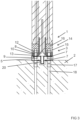
- the method comprises a connecting step for connecting the prefabricated construction element 1 by means of repeatably openable and closable mechanical connection means 3 to said another construction element 2 so that a joint 4 is formed between the prefabricated construction element 1 and said another construction element 2 and so that the joint 4 is at least partly limited by the prefabricated construction element 1 and said another construction element 2.
- the method comprises a grouting step for grouting the joint 4 by covering such as filling the joint 4 at least partly with grout 5 and allowing the grout 5 to harden.
- the method comprises a coating step for coating surfaces 6 of the prefabricated construction element 1 that is to be covered by grout 5 in said grouting step at least partly with separation means 7 such as with anti-adhesion means prior said grouting step.
- mechanical anti-adhesion means such as perforated or unperforated plates, sheets or films be used as separation means 7.
- mechanical anti-adhesion means can for example be used an expanded steel sheet, a perforated steel sheet, a plate of polymer, a sheet of polymer, a film of polymer, a textile sheet, a fabric sheet, formwork liner, and wood such as coated plywood.
- An advantage that is achieved by using a perforated plate, sheet or a film as a separation means 7 is that the perforations allows for grout 5 to attach to the prefabricated construction element 1 through the separation means 7. This provides for a stronger connection between the grout 5 and the prefabricated construction element 1 while allowing for easy detaching of the prefabricated construction element 1 from the separation means 7 and from the grout 5.
- anti-adhesion substances such as fluid for example oil, cementitious retarder, or carbon be used as separation means 7.
- the coating step includes preferably, but not necessarily, providing for the coating step a separation means 7 that is a means separate from the prefabricated construction element 1, i.e. that does not form a part of the prefabricated construction element 1, and that is a means separate from said another construction element 2, i.e. that does not form a part of said another construction element 2.
- the separation means 7 is preferably, but not necessarily, arranged to at least partly follow an interface (not marked with a reference numeral) i.e. a connection surface between the grout 5 that is configured to cover the prefabricated construction element 1 in the joint 4 and the surfaces 6 of the prefabricated construction element 1.
- the method allows easy removal of the prefabricated construction element 1 from grouting without damaging the prefabricated construction element 1, because the grout 5 will not adhere to the surfaces 6 of the prefabricated construction element 1 because of the separation means 7.
- the coating step includes preferably, but not necessarily, additionally coating surfaces 6 of said another construction element 2 that is to be covered by grout 5 at least partly with separation means 7 such as with any alternative of the separation means 7 presented prior said grouting.
- the separation means 7 is preferably, but not necessarily, arranged to at least partly follow an interface (not marked with a reference numeral) i.e. a connection surface between the grout 5 that is configured to cover said another construction element 2 in the joint 4 and the surfaces 6 of said another construction element 2.
- the method allows easy removal of the from the said another construction element 2 without damaging said another construction element 2, because the grout 5 will not adhere to the surfaces 6 of said another construction element 2 coated by separation means 7.
- the connecting step includes, as illustrated in figures 1 to 7 , providing repeatably openable and closable mechanical connection means 3 comprising anchor bolts 8 extending from said another construction element 2.
- the connection step includes screwing first nuts 9 on the anchor bolts 8 so that the nuts are at a distance from said another construction element 2, as illustrated in figures 1 to 3 .
- the connection step includes arranging the anchor bolts 8 to penetrate openings 10 in the prefabricated construction element 1 so that the first nuts 9 are between said another construction element 2 and the prefabricated construction element 1 and a grouting space 11 is formed between said another construction element 2 and the prefabricated construction element 1.
- the connection step includes screwing second nuts 12 to the anchor bolts 8 to secure the prefabricated construction element 1 to the anchor bolts 8.
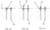
- a washer 17 is arranged at the anchor bolts 8 between the openings 10 and second nuts 12.
- the method includes preferably, but not necessarily, arranging in the connection step the anchor bolts 8 to penetrate openings 10 formed in metal plates 13 of connector elements 14 at least partly cast into the concrete of the prefabricated construction element 1.
- connector element 14 can for example be in the form of a column shoe, as illustrated in the embodiments shown in figures 1 to 3 , a beam shoe, as illustrated in the embodiment illustrated in figure 7 , or a wall shoe, as illustrated in the embodiments shown in figures 4 and 5 , depending on the form of the prefabricated construction element 1.
- connection step includes arranging the anchor bolts 8 to penetrate openings 10 in the prefabricated construction element 1 so that the anchor bolts 8 extend into a cavity 15 in the prefabricated construction element 1, and the connection step includes screwing said second nuts 12 to the anchor bolts 8 inside the cavities so that the second nuts 12 will be housed in the cavities.
- the method includes a filling step for filling the cavities at least partly with other material 16 than grout 5 prior said grouting step to at least partly prevent grout 5 from entering said cavities.
- At least one of mineral wool, gypsum, plaster and lime mortar is used as said other material 16 in the filling step. These materials are easier to remove than concrete or mortar so that the repeatably openable and closable mechanical connection means 3 can be accessed in the cavity 15 and be opened, as exemplified in figure 8 .
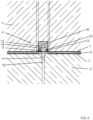
- the method can include providing the prefabricated construction element 1 with at least one of a projection formation 20 configured to project into grout 5 in the joint between the prefabricated construction element 1 and said another construction element 2 and a cavity formation 21 into which grout 5 from the joint between the prefabricated construction element 1 and said another construction element 2 is configured to project.
- the method can include providing said another construction element 2 with at least one of a projection formation 20 configured to project into grout 5 in the joint between the prefabricated construction element 1 and said another construction element 2, and a cavity formation 21 into which grout 5 from the joint between the prefabricated construction element 1 and said another construction element 2 is configured to project.
- the construction element 1 can be provided with a formation 20 that extend into a cavity 21 in the grout 5 between the prefabricated construction element 1 and said another construction element 2, as illustrated in figure 2 .
- construction element 1 can alternatively be provided with a formation 20 that extend into a cavity 21 in said another construction element 2, as illustrated in figure 3 .
- shear force transfer capacity between the prefabricated construction element 1 and said another construction element 2 be increased, while still creating an easily dismountable connection allowing reuse of a least the construction element 1, by forming a cavity 21 in the surface 6 of the prefabricated construction element 1 so that the cavity 21 is configured to be filled with the grout 5 cast between the prefabricated construction element 1 and said another construction element 2, as illustrated in figure 5 .
- shear force transfer capacity between the prefabricated construction element 1 and said another construction element 2 be increased, while still creating an easily dismountable connection allowing reuse of a least the construction element 1, by forming a cavity 21 both in the surface 6 of the prefabricated construction element 1 and in the surface 6 of said another construction element so that both cavities 21 are configured to be filled with the grout 5 cast between the prefabricated construction element 1 and said another construction element 2, as illustrated in figure 6 .
- the anchor bolts 8 are preferably, but not necessarily, threaded bars, which are screwed into threaded muffs 17, which are casted into concrete of said another construction element 2 so that the threaded muffs 17 extend from the surface 6 of said another construction element 2 into said another construction element 2, and which are anchored by means of anchoring means 18 fastened to said threaded muffs 17 and also casted into concrete of said another construction element 2.
- An example of such is Copra ® anchoring coupler by Peikko Group.
- the prefabricated construction element 1 comprising concrete can for example be any one of a prefabricated reinforced concrete column/pile/pillar, as illustrated in figures 1 to 3 , a prefabricated reinforced concrete beam, as illustrated in figure 7 , and a prefabricated concrete wall element, as illustrated in figures 4 to 6 .
- Said another construction element 2 can also be a prefabricated construction element 1 comprising concrete for example a prefabricated reinforced concrete column/pile/pillar, as illustrated in figure 7 .
- said another construction element 2 can be a cast-in-situ construction element comprising concrete such as a reinforced concrete foundation or a part belonging to a reinforced concrete foundation, as illustrated in figures 1 to 6 .
- the prefabricated construction element 1 is connected by means of repeatably openable and closable mechanical connection means 3 to said another construction element 2 so that a joint 4 is formed between the prefabricated construction element 1 and said another construction element 2 and so that the joint 4 is at least partly limited by the prefabricated construction element 1 and said another construction element 2.
- the joint 4 is at least partly covered such as filled with grout 5 that is allowed to harden.
- separation means 7 such as anti-adhesion means 7 is present between surfaces 6 of the prefabricated construction element 1 that is at least partly covered by grout 5 and said grout 5 at least partly covering the joint 4 and that allowed to harden.
- the separation means 7 can comprise mechanical anti-adhesion means such as perforated or unperforated plates, sheets or films.
- Mechanical anti-adhesion means can for example be an expanded steel sheet, a perforated steel sheet, a plate of polymer, a sheet of polymer, a film of polymer, a textile sheet, a fabric sheet, formwork liner, and wood such as coated plywood.
- An advantage that is achieved by using a perforated plate, sheet or a film as a separation means 7 is that the perforations allows for grout 5 to attach to the prefabricated construction element 1 through the separation means 7. This provides for a stronger connection between the grout 5 and the prefabricated construction element 1 while allowing for easy detaching of the prefabricated construction element 1 from the separation means 7 and from the grout 5.
- the separation means 7 can comprise anti-adhesion substances such as fluid for example oil or carbon.
- the separation means 7 is preferably, but not necessarily, a means separate from the prefabricated construction element 1, i.e. not a part of the prefabricated construction element, and a means separate from said another construction element 2, i.e. not a part of said another construction element 2.
- the separation means 7 follows preferably, but not necessarily, at least partly an interface (not marked with a reference numeral) i.e. a connection surface between the grout 5 that covers the prefabricated construction element 1 in the joint 4 and the surfaces 6 of the prefabricated construction element 1.
- connection arrangement allows easy removal of the prefabricated construction element 1 from grouting without damaging the prefabricated construction element 1, because the grout 5 will not adhere to the surfaces 6 of the prefabricated construction element 1 coated by anti-adhesion substance 7.
- separation means 7 such as any alternative of the separation means 7 as presented is preferably also present between surfaces 6 of said another construction element 2 that is at least partly covered by grout 5 and said grout 5 at least partly covering the joint 4 and that is allowed to harden.
- An advantage of this is that this allows easy removal of the grouting from the other construction element, because the grout 5 will not adhere to the surfaces 6 of said another construction element 2 coated by anti-adhesion substance 7.
- the separation means 7 follows preferably, but not necessarily, at least partly an interface (not marked with a reference numeral) i.e. a connection surface between the grout 5 that covers said another construction element 2 in the joint 4 and the surfaces 6 of said another construction element 2.
- connection arrangement includes, as illustrated in figures 1 to 7 , repeatably openable and closable mechanical connection means 3 comprising anchor bolts 8 extending from said another construction element 2.
- the repeatably openable and closable mechanical connection means 3 include first nuts 9 screwed on the anchor bolts 8 so that the nuts are at a distance from said another construction element 2, as illustrated in figures 1 to 3 .
- the anchor bolts 8 can penetrate openings 10 in the prefabricated construction element 1 so that the first nuts 9 are between said another construction element 2 and the prefabricated construction element 1 and so that a grouting space 11 is formed between said another construction element 2 and the prefabricated construction element 1.
- the repeatably openable and closable mechanical connection means 3 include second nuts 12 screwed to the anchor bolts 8 to secure the prefabricated construction element 1 to the anchor bolts 8.
- a washer 17 is arranged at the anchor bolts 8 between the openings 10 and second nuts 12.
- the anchor bolts 8 can penetrate openings 10 formed in metal plates 13 of connector elements 14 at least partly cast into the concrete of the prefabricated construction element 1.
- Such connector element 14 can for example be in the form of a column shoe, as illustrated in the embodiments shown in figures 1 to 3 , a beam shoe, as illustrated in the embodiment illustrated in figure 7 , or a wall shoe, as illustrated in the embodiments shown in figures 4 and 5 , depending on the form of the prefabricated construction element 1.
- the anchor bolts 8 penetrate in the connection arrangement openings 10 in the prefabricated construction element 1 so that the anchor bolts 8 extend into a cavity 15 in the prefabricated construction element 1, and said second nuts 12 are screwed to the anchor bolts 8 inside the cavities so that the second nuts 12 are housed in the cavities.
- the cavities are at least partly with other material 16 than grout 5 prior said grouting step to at least partly prevent grout 5 from entering said cavities.
- At least one of mineral wool, gypsum, plaster and lime mortar are used as said other material 16 in the filling step. These materials are easier to remove than concrete or mortar so that the repeatably openable and closable mechanical connection means 3 can be accessed in the cavity 15 and be opened, as exemplified in figure 8 .
- the prefabricated construction element 1 can be provided with at least one of a projection formation 20 that projects into grout 5 in the joint between the prefabricated construction element 1 and said another construction element 2 and a cavity formation 21 into which grout 5 from the joint between the prefabricated construction element 1 and said another construction element 2 projects.
- said another construction element 2 can be provided with at least one of a projection formation 20 that projects into grout 5 in the joint between the prefabricated construction element 1 and said another construction element 2, and a cavity formation 21 into which grout 5 from the joint between the prefabricated construction element 1 and said another construction element 2 projects.
- the construction element 1 can be provided with a formation 20 that extend into a cavity 21 in the grout 5 between the prefabricated construction element 1 and said another construction element 2, as illustrated in figure 2 .
- construction element 1 can alternatively be provided with a formation 20 that extend into a cavity 21 in said another construction element 2, as illustrated in figure 3 .
- shear force transfer capacity between the prefabricated construction element 1 and said another construction element 2 be increased, while still creating an easily dismountable connection allowing reuse of a least the construction element 1, by forming a cavity 21 in the surface 6 of the prefabricated construction element 1 so that the cavity 21 is configured to be filled with the grout 5 cast between the prefabricated construction element 1 and said another construction element 2, as illustrated in figure 5 .
- shear force transfer capacity between the prefabricated construction element 1 and said another construction element 2 be increased, while still creating an easily dismountable connection allowing reuse of a least the construction element 1, by forming a cavity 21 both in the surface 6 of the prefabricated construction element 1 and in the surface 6 of said another construction element so that both cavities 21 are configured to be filled with the grout 5 cast between the prefabricated construction element 1 and said another construction element 2, as illustrated in figure 6 .
- the anchor bolts 8 are preferably, but not necessarily, threaded bars, which are screwed into threaded muffs 17, which are casted into concrete of said another construction element 2 so that the threaded muffs 17 extend from the surface 6 of said another construction element 2 into said another construction element 2, and which are anchored by means of anchoring means 18 fastened to said threaded muffs 17 and also casted into concrete of said another construction element 2.
- An example of such is Copra ® anchoring coupler by Peikko Group.
Landscapes
- Engineering & Computer Science (AREA)
- Architecture (AREA)
- Civil Engineering (AREA)
- Structural Engineering (AREA)
- Physics & Mathematics (AREA)
- Electromagnetism (AREA)
- Mechanical Engineering (AREA)
- Joining Of Building Structures In Genera (AREA)
Claims (16)
- Verfahren zur Montage eines Beton umfassenden vorgefertigten Bauelements (1) an einem anderen Bauelement (2), wobei das Verfahren umfasst:einen Verbindungsschritt zum Verbinden des vorgefertigten Bauelements (1) mit einem anderen Bauelement (2) mittels wiederholt öffnungs- und schließfähiger mechanischer Verbindungsmittel (3) dergestalt, dass zwischen dem vorgefertigten Bauelement (1) und dem anderen Bauelement (2) eine Fuge (4) ausgebildet wird,einen Vergussschritt zum Vergießen der Fuge (4), indem die Fuge (4) mindestens teilweise mit Vergussmörtel (5) bedeckt wird und der Vergussmörtel (5) aushärten gelassen wird, undeinen Beschichtungsschritt zum mindestens teilweisen Beschichten von Oberflächen (6) des im Vergussschritt mit Vergussmörtel (5) zu bedeckenden vorgefertigten Bauelements (1) mit einem Trennmittel (7) vor dem Vergussschritt,wobei der Verbindungsschritt umfasst: Bereitstellen von wiederholt öffnungs- und schließfähigen mechanischen Verbindungsmitteln (3), die aus dem anderen Bauelement (2) herausragende Ankerschrauben (8) umfassen,wobei der Verbindungsschritt umfasst: Aufschrauben erster Muttern (9) auf die Ankerschrauben (8) dergestalt, dass die Muttern einen Abstand zum anderen Bauelement (2) aufweisen,wobei der Verbindungsschritt umfasst: Anordnen der Ankerschrauben (8) dergestalt, dass sie Öffnungen (10) im vorgefertigten Bauelement (1) durchdringen, so dass die ersten Muttern (9) sich zwischen dem anderen Bauelement (2) und dem vorgefertigten Bauelement (1) befinden und ein Vergussraum (11) zwischen dem anderen Bauelement (2) und dem vorgefertigten Bauelement (1) ausgebildet wird,wobei der Verbindungsschritt umfasst: Aufschrauben zweiter Muttern (12) auf die Ankerschrauben (8), um das vorgefertigte Bauelement (1) an den Ankerschrauben (8) zu befestigen,wobei der Verbindungsschritt umfasst: Anordnen der Ankerschrauben (8) dergestalt, dass sie Öffnungen (10) im vorgefertigten Bauelement (1) durchdringen, so dass die Ankerschrauben (8) in einen Hohlraum (15) im vorgefertigten Bauelement (1) hineinragen,wobei der Verbindungsschritt umfasst: Aufschrauben der zweiten Muttern (12) auf die Ankerschrauben (8) im Inneren der Hohlräume, so dass die zweiten Muttern (12) in die Hohlräume aufgenommen werden,gekennzeichnetdurch einen Füllschritt zum mindestens teilweisen Füllen der Hohlräume mit einem anderen Material (16), das kein Vergussmörtel (5) ist, vor dem Vergussschritt, um das Eintreten von Vergussmörtel (5) in die Hohlräume mindestens teilweise zu verhindern, unddadurch, dass als das andere Material (16) im Füllschritt mindestens eines von Mineralwolle, Gips, Gipsmörtel und Kalkmörtel verwendet wird.
- Verfahren nach Anspruch 1, gekennzeichnet dadurch,
dass das Trennmittel (7) so eingerichtet ist, dass es mindestens teilweise einer Grenzfläche zwischen dem für das Bedecken des vorgefertigten Bauelements (1) in der Fuge (4) ausgelegten Vergussmörtel (5) und dem vorgefertigten Bauelement (1) folgt. - Verfahren nach Anspruch 1 oder 2, gekennzeichnet dadurch,
dass der Beschichtungsschritt zusätzlich umfasst: mindestens teilweises Beschichten von Oberflächen (6) des mit Vergussmörtel (5) zu bedeckenden anderen Bauelements (2) mit einem Trennmittel (7) vor dem Verguss. - Verfahren nach Anspruch 3, gekennzeichnet dadurch,
dass das Trennmittel (7) so eingerichtet ist, dass es mindestens teilweise einer Grenzfläche zwischen dem zum Bedecken des anderen Bauelements (2) in der Fuge (4) ausgelegten Vergussmörtel (5) und dem anderen Bauelement (2) folgt. - Verfahren nach einem der Ansprüche 1 bis 4, gekennzeichnet dadurch,
dass als Ankerschrauben (8) Gewindestangen bereitgestellt werden, die in Gewindehülsen (17) eingeschraubt werden, die in Beton des anderen Bauelements (2) dergestalt gegossen werden, dass sich die Gewindehülsen (17) von der Oberfläche (6) des anderen Bauelements (2) in das andere Bauelement (2) hinein erstrecken, und die mittels Verankerungsmitteln (18), die an den Gewindehülsen (17) befestigt und auch in Beton des anderen Bauelements (2) gegossen werden, verankert werden. - Verfahren nach einem der Ansprüche 1 bis 5, gekennzeichnet dadurch,
dass für den Beschichtungsschritt ein Trennmittel (7) bereitgestellt wird, das ein vom vorgefertigten Bauelement (1) separates Mittel ist und das ein vom anderen Bauelement (2) separates Mittel ist. - Verfahren nach einem der Ansprüche 1 bis 6, gekennzeichnet durch
Versehen des vorgefertigten Bauelements (1) mit einer Vorsprungformation (20), die dazu ausgelegt ist, in den Vergussmörtel (5) in der Fuge zwischen dem vorgefertigten Bauelement (1) und dem anderen Bauelement (2) hineinzuragen, und/oder einer Hohlraumformation (21), in die Vergussmörtel (5) aus der Fuge zwischen dem vorgefertigten Bauelement (1) und dem anderen Bauelement (2) hineinzuragen ausgelegt ist. - Verfahren nach einem der Ansprüche 1 bis 7, gekennzeichnet durch
Versehen des anderen Bauelements (2) mit einer Vorsprungformation (20), die dazu ausgelegt ist, in den Vergussmörtel (5) in der Fuge zwischen dem vorgefertigten Bauelement (1) und dem anderen Bauelement (2) hineinzuragen, und/oder einer Hohlraumformation (21), in die Vergussmörtel (5) aus der Fuge zwischen dem vorgefertigten Bauelement (1) und dem anderen Bauelement (2) hineinzuragen ausgelegt ist. - Verbindungsanordnung zwischen einem Beton umfassenden vorgefertigten Bauelement (1) und einem anderen Bauelement (2), wobei in der Verbindungsanordnungdas vorgefertigte Bauelement (1) mittels wiederholt öffnungs- und schließfähiger mechanischer Verbindungsmittel (3) mit dem anderen Bauelement (2) dergestalt verbunden ist, dass eine Fuge (4) zwischen dem vorgefertigten Bauelement (1) und dem anderen Bauelement (2) ausgebildet ist, unddie Fuge (4) mindestens teilweise mit Vergussmörtel (5) bedeckt ist, der aushärten gelassen wird,durch ein Trennmittel (7) zwischen Oberflächen (6) des mindestens teilweise mit Vergussmörtel (5) bedeckten vorgefertigten Bauelements (1) und den Vergussmörtel (5), der die Fuge (4) mindestens teilweise bedeckt und der härten gelassen wurde,die wiederholt öffnungs- und schließfähigen mechanischen Verbindungsmittel (3) Ankerschrauben (8) umfassen, die aus dem anderen Bauelement (2) herausragen,erste Muttern (9) auf den Ankerschrauben (8) aufgeschraubt sind, so dass die Muttern in einem Abstand zum anderen Bauelement (2) gelegen sind,die Ankerschrauben (8) Öffnungen (10) im vorgefertigten Bauelement (1) durchdringen, so dass die ersten Muttern (9) sich zwischen dem anderen Bauelement (2) und dem vorgefertigten Bauelement (1) befinden und ein Vergussraum (11) zwischen dem anderen Bauelement (2) und dem vorgefertigten Bauelement (1) ausgebildet ist, undzweite Muttern (12) auf die Ankerschrauben (8) aufgeschraubt sind, um das vorgefertigte Bauelement (1) an den Ankerschrauben (8) zu befestigen,die Ankerschrauben (8) die Öffnungen (10) im vorgefertigten Bauelement (1) durchdringen, so dass die Ankerschrauben (8) in einen Hohlraum (15) im vorgefertigten Bauelement (1) hineinragen, unddie zweiten Muttern (12) auf die Ankerschrauben (8) im Inneren der Hohlräume aufgeschraubt sind, so dass die zweiten Muttern (12) in die Hohlräume aufgenommen sind,gekennzeichnet dadurch,dass die Hohlräume mindestens teilweise mit einem anderen Material (16), das kein Vergussmörtel (5) ist, gefüllt sind, um das Eintreten von Vergussmörtel (5) in die Hohlräume mindestens teilweise zu verhindern, unddass das andere Material (16) mindestens eines von Mineralwolle, Gips, Gipsmörtel und Kalkmörtel umfasst.
- Verbindungsanordnung nach Anspruch 9, gekennzeichnet dadurch,
dass das Trennmittel (7) mindestens teilweise einer Grenzfläche zwischen dem Vergussmörtel (5), der das vorgefertigte Bauelement (1) in der Fuge (4) bedeckt, und dem vorgefertigten Bauelement (1) folgt. - Verbindungsanordnung nach Anspruch 9 oder 10, gekennzeichnet
durch Trennmittel (7) zwischen Oberflächen (6) des anderen Bauelements (2), das mindestens teilweise mit Vergussmörtel (5) bedeckt ist, und dem Vergussmörtel (5), der mindestens teilweise die Fuge (4) bedeckt und der härten gelassen wurde. - Verbindungsanordnung nach einem der Ansprüche 9 bis 11, gekennzeichnet dadurch,
dass das Trennmittel (7) mindestens teilweise einer Grenzfläche zwischen dem Vergussmörtel (5), der das andere Bauelement (2) in der Fuge (4) bedeckt, und dem anderen Bauelement (2) folgt. - Verbindungsanordnung nach einem der Ansprüche 9 bis 12, gekennzeichnet dadurch,
dass die Ankerschrauben (8) Gewindestangen sind, die in Gewindehülsen (17) eingeschraubt sind, die in Beton des anderen Bauelements (2) dergestalt gegossen sind, dass sich die Gewindehülsen (17) von der Oberfläche (6) des anderen Bauelements (2) in das andere Bauelement (2) hinein erstrecken, und die mittels Verankerungsmitteln (18), die an den Gewindehülsen (17) befestigt und auch in Beton des anderen Bauelements (2) gegossen sind, verankert sind. - Verbindungsanordnung nach einem der Ansprüche 9 bis 13, gekennzeichnet dadurch,
dass das Trennmittel (7) ein vom vorgefertigten Bauelement (1) separates Mittel ist und ein vom anderen Bauelement (2) separates Mittel ist. - Verbindungsanordnung nach einem der Ansprüche 9 bis 14, gekennzeichnet dadurch,
dass das vorgefertigte Bauelement (1) mit einer Vorsprungformation (20), die in den Vergussmörtel (5) in der Fuge zwischen dem vorgefertigten Bauelement (1) und dem anderen Bauelement (2) hineinragt, und/oder einer Hohlraumformation (21), in die Vergussmörtel (5) aus der Fuge zwischen dem vorgefertigten Bauelement (1) und dem anderen Bauelement (2) hineinragt, versehen ist. - Verbindungsanordnung nach einem der Ansprüche 9 bis 15, gekennzeichnet dadurch,
dass das andere Bauelement (2) mit einer Vorsprungformation (20), die in den Vergussmörtel (5) in der Fuge zwischen dem vorgefertigten Bauelement (1) und dem anderen Bauelement (2) hineinragt, und/oder einer Hohlraumformation (21), in die Vergussmörtel (5) aus der Fuge zwischen dem vorgefertigten Bauelement (1) und dem anderen Bauelement (2) hineinragt, versehen ist.
Applications Claiming Priority (2)
| Application Number | Priority Date | Filing Date | Title |
|---|---|---|---|
| FI20195517 | 2019-06-14 | ||
| PCT/FI2020/050363 WO2020249852A1 (en) | 2019-06-14 | 2020-05-29 | Method for mounting a prefabricated construction element to another construction element and connection arrangement |
Publications (3)
| Publication Number | Publication Date |
|---|---|
| EP3983618A1 EP3983618A1 (de) | 2022-04-20 |
| EP3983618C0 EP3983618C0 (de) | 2023-07-26 |
| EP3983618B1 true EP3983618B1 (de) | 2023-07-26 |
Family
ID=71069869
Family Applications (1)
| Application Number | Title | Priority Date | Filing Date |
|---|---|---|---|
| EP20731524.3A Active EP3983618B1 (de) | 2019-06-14 | 2020-05-29 | Verfahren zur montage eines vorgefertigten bauelements an ein anderes bauelement und verbindungsanordnung |
Country Status (7)
| Country | Link |
|---|---|
| EP (1) | EP3983618B1 (de) |
| KR (1) | KR102619755B1 (de) |
| CN (1) | CN114174610B (de) |
| ES (1) | ES2961083T3 (de) |
| HU (1) | HUE063667T2 (de) |
| PL (1) | PL3983618T3 (de) |
| WO (1) | WO2020249852A1 (de) |
Families Citing this family (1)
| Publication number | Priority date | Publication date | Assignee | Title |
|---|---|---|---|---|
| CN114960390A (zh) * | 2022-06-01 | 2022-08-30 | 中铁第四勘察设计院集团有限公司 | 一种预埋式脱空注浆装置及注浆施工方法 |
Family Cites Families (8)
| Publication number | Priority date | Publication date | Assignee | Title |
|---|---|---|---|---|
| US3775928A (en) * | 1972-03-09 | 1973-12-04 | Descon Concordia Syst Ltd | Erection method for structural system |
| DE102004017006B4 (de) * | 2004-04-02 | 2012-03-29 | Aloys Wobben | Verfahren zum Errichten eines Turmes |
| DE102004017008B4 (de) * | 2004-04-02 | 2009-10-22 | Aloys Wobben | Verfahren zum Errichten eines Turmes |
| ITMI20051565A1 (it) * | 2005-08-11 | 2007-02-12 | Edilmatic S R L | Dispositivo di interconnessione per collegare una trave ad un pilastro prefabbricati in cemento armato e metodo per collegare la trave al pilastro per mezzo di tale dispositivo |
| US8037651B2 (en) * | 2008-03-19 | 2011-10-18 | Clifford Dent | Ground anchor assembly |
| US20110131899A1 (en) * | 2010-04-30 | 2011-06-09 | Stefan Voss | Apparatus and method for producing a concrete foundation |
| IT1403484B1 (it) * | 2010-10-29 | 2013-10-17 | Sar Costruzioni Prefabbricate S R L | Struttura di fondazione particolarmente per edifici prefabbricati |
| FI123856B (fi) * | 2011-06-20 | 2013-11-29 | Peikko Group Oy | Liitäntälaite vierekkäisten betonielementtiosien kiinnittämiseen ja menetelmä ensimmäisen ja toisen betonielementtiosan yhdistämiseksi |
-
2020
- 2020-05-29 CN CN202080043599.0A patent/CN114174610B/zh active Active
- 2020-05-29 EP EP20731524.3A patent/EP3983618B1/de active Active
- 2020-05-29 PL PL20731524.3T patent/PL3983618T3/pl unknown
- 2020-05-29 KR KR1020217040790A patent/KR102619755B1/ko active IP Right Grant
- 2020-05-29 WO PCT/FI2020/050363 patent/WO2020249852A1/en active Application Filing
- 2020-05-29 HU HUE20731524A patent/HUE063667T2/hu unknown
- 2020-05-29 ES ES20731524T patent/ES2961083T3/es active Active
Also Published As
| Publication number | Publication date |
|---|---|
| ES2961083T3 (es) | 2024-03-08 |
| WO2020249852A1 (en) | 2020-12-17 |
| EP3983618C0 (de) | 2023-07-26 |
| KR20220009418A (ko) | 2022-01-24 |
| CN114174610A (zh) | 2022-03-11 |
| EP3983618A1 (de) | 2022-04-20 |
| PL3983618T3 (pl) | 2023-10-09 |
| KR102619755B1 (ko) | 2023-12-29 |
| HUE063667T2 (hu) | 2024-01-28 |
| CN114174610B (zh) | 2024-04-09 |
Similar Documents
| Publication | Publication Date | Title |
|---|---|---|
| RU2375523C1 (ru) | Опалубка для создания усиливающей оболочки конструкции из гофрированных стальных листов | |
| WO2011114507A1 (ja) | 新設地下構造物の施工方法 | |
| EP3983618B1 (de) | Verfahren zur montage eines vorgefertigten bauelements an ein anderes bauelement und verbindungsanordnung | |
| EP3336260A1 (de) | Methode zum bauen eines turmfundaments | |
| JP3780816B2 (ja) | 既存建物の免震構造化方法 | |
| JPS5916621B2 (ja) | 地下タンクの側壁構築方法 | |
| CN215715401U (zh) | 一种可拆卸土钉墙结构 | |
| KR100728266B1 (ko) | 무지주 지하 옹벽 거푸집 시공의 흙막이와 인장와이어연결구조 | |
| JP5356085B2 (ja) | 仮設支柱の基礎構造及びその構築方法 | |
| RU2037604C1 (ru) | Способ усиления фундамента здания, сооружения | |
| JP3641227B2 (ja) | 地下構造躯体の施工法 | |
| EA044430B1 (ru) | Способ крепления предварительно изготовленного строительного элемента к другому строительному элементу и соединительное устройство | |
| JPH01268971A (ja) | 既設構造物の組積造壁体の移築工法 | |
| JP4511080B2 (ja) | 地下構造物の構築方法 | |
| JPH05179647A (ja) | 山留め壁の支保構造 | |
| JP2686570B2 (ja) | ケーソン底版の構築方法 | |
| JPS63280153A (ja) | 地下躯体の逆打ち工法 | |
| JP2003147784A (ja) | 鋼製型枠支保工 | |
| JP2000064314A (ja) | 基礎構造躯体の構築方法 | |
| CN219654016U (zh) | 一种带互锁构造的叠合剪力墙 | |
| RU2119022C1 (ru) | Способ возведения монолитных стен зданий | |
| JP3718701B2 (ja) | 既存建物への免震装置組込み方法 | |
| JP3797754B2 (ja) | 地下躯体底版の構築方法 | |
| EP2907925B1 (de) | Verstärkung einer Rückhaltewand | |
| KR200410018Y1 (ko) | 파형강판 구조물의 보강구조 |
Legal Events
| Date | Code | Title | Description |
|---|---|---|---|
| STAA | Information on the status of an ep patent application or granted ep patent |
Free format text: STATUS: UNKNOWN |
|
| STAA | Information on the status of an ep patent application or granted ep patent |
Free format text: STATUS: THE INTERNATIONAL PUBLICATION HAS BEEN MADE |
|
| PUAI | Public reference made under article 153(3) epc to a published international application that has entered the european phase |
Free format text: ORIGINAL CODE: 0009012 |
|
| STAA | Information on the status of an ep patent application or granted ep patent |
Free format text: STATUS: REQUEST FOR EXAMINATION WAS MADE |
|
| 17P | Request for examination filed |
Effective date: 20211230 |
|
| AK | Designated contracting states |
Kind code of ref document: A1 Designated state(s): AL AT BE BG CH CY CZ DE DK EE ES FI FR GB GR HR HU IE IS IT LI LT LU LV MC MK MT NL NO PL PT RO RS SE SI SK SM TR |
|
| DAV | Request for validation of the european patent (deleted) | ||
| DAX | Request for extension of the european patent (deleted) | ||
| GRAP | Despatch of communication of intention to grant a patent |
Free format text: ORIGINAL CODE: EPIDOSNIGR1 |
|
| STAA | Information on the status of an ep patent application or granted ep patent |
Free format text: STATUS: GRANT OF PATENT IS INTENDED |
|
| INTG | Intention to grant announced |
Effective date: 20230314 |
|
| GRAS | Grant fee paid |
Free format text: ORIGINAL CODE: EPIDOSNIGR3 |
|
| GRAA | (expected) grant |
Free format text: ORIGINAL CODE: 0009210 |
|
| STAA | Information on the status of an ep patent application or granted ep patent |
Free format text: STATUS: THE PATENT HAS BEEN GRANTED |
|
| AK | Designated contracting states |
Kind code of ref document: B1 Designated state(s): AL AT BE BG CH CY CZ DE DK EE ES FI FR GB GR HR HU IE IS IT LI LT LU LV MC MK MT NL NO PL PT RO RS SE SI SK SM TR |
|
| REG | Reference to a national code |
Ref country code: CH Ref legal event code: EP |
|
| REG | Reference to a national code |
Ref country code: IE Ref legal event code: FG4D |
|
| REG | Reference to a national code |
Ref country code: DE Ref legal event code: R096 Ref document number: 602020014473 Country of ref document: DE |
|
| U01 | Request for unitary effect filed |
Effective date: 20230821 |
|
| U07 | Unitary effect registered |
Designated state(s): AT BE BG DE DK EE FI FR IT LT LU LV MT NL PT SE SI Effective date: 20230828 |
|
| REG | Reference to a national code |
Ref country code: NO Ref legal event code: T2 Effective date: 20230726 |
|
| REG | Reference to a national code |
Ref country code: SK Ref legal event code: T3 Ref document number: E 42112 Country of ref document: SK |
|
| REG | Reference to a national code |
Ref country code: LT Ref legal event code: MG9D |
|
| PG25 | Lapsed in a contracting state [announced via postgrant information from national office to epo] |
Ref country code: GR Free format text: LAPSE BECAUSE OF FAILURE TO SUBMIT A TRANSLATION OF THE DESCRIPTION OR TO PAY THE FEE WITHIN THE PRESCRIBED TIME-LIMIT Effective date: 20231027 |
|
| PG25 | Lapsed in a contracting state [announced via postgrant information from national office to epo] |
Ref country code: IS Free format text: LAPSE BECAUSE OF FAILURE TO SUBMIT A TRANSLATION OF THE DESCRIPTION OR TO PAY THE FEE WITHIN THE PRESCRIBED TIME-LIMIT Effective date: 20231126 |
|
| REG | Reference to a national code |
Ref country code: HU Ref legal event code: AG4A Ref document number: E063667 Country of ref document: HU |
|
| PG25 | Lapsed in a contracting state [announced via postgrant information from national office to epo] |
Ref country code: RS Free format text: LAPSE BECAUSE OF FAILURE TO SUBMIT A TRANSLATION OF THE DESCRIPTION OR TO PAY THE FEE WITHIN THE PRESCRIBED TIME-LIMIT Effective date: 20230726 Ref country code: IS Free format text: LAPSE BECAUSE OF FAILURE TO SUBMIT A TRANSLATION OF THE DESCRIPTION OR TO PAY THE FEE WITHIN THE PRESCRIBED TIME-LIMIT Effective date: 20231126 Ref country code: HR Free format text: LAPSE BECAUSE OF FAILURE TO SUBMIT A TRANSLATION OF THE DESCRIPTION OR TO PAY THE FEE WITHIN THE PRESCRIBED TIME-LIMIT Effective date: 20230726 Ref country code: GR Free format text: LAPSE BECAUSE OF FAILURE TO SUBMIT A TRANSLATION OF THE DESCRIPTION OR TO PAY THE FEE WITHIN THE PRESCRIBED TIME-LIMIT Effective date: 20231027 |
|
| REG | Reference to a national code |
Ref country code: ES Ref legal event code: FG2A Ref document number: 2961083 Country of ref document: ES Kind code of ref document: T3 Effective date: 20240308 |
|
| PG25 | Lapsed in a contracting state [announced via postgrant information from national office to epo] |
Ref country code: SM Free format text: LAPSE BECAUSE OF FAILURE TO SUBMIT A TRANSLATION OF THE DESCRIPTION OR TO PAY THE FEE WITHIN THE PRESCRIBED TIME-LIMIT Effective date: 20230726 Ref country code: RO Free format text: LAPSE BECAUSE OF FAILURE TO SUBMIT A TRANSLATION OF THE DESCRIPTION OR TO PAY THE FEE WITHIN THE PRESCRIBED TIME-LIMIT Effective date: 20230726 |