EP3983618B1 - Method for mounting a prefabricated construction element to another construction element and connection arrangement - Google Patents
Method for mounting a prefabricated construction element to another construction element and connection arrangement Download PDFInfo
- Publication number
- EP3983618B1 EP3983618B1 EP20731524.3A EP20731524A EP3983618B1 EP 3983618 B1 EP3983618 B1 EP 3983618B1 EP 20731524 A EP20731524 A EP 20731524A EP 3983618 B1 EP3983618 B1 EP 3983618B1
- Authority
- EP
- European Patent Office
- Prior art keywords
- construction element
- prefabricated
- grout
- another construction
- another
- Prior art date
- Legal status (The legal status is an assumption and is not a legal conclusion. Google has not performed a legal analysis and makes no representation as to the accuracy of the status listed.)
- Active
Links
- 238000010276 construction Methods 0.000 title claims description 291
- 238000000034 method Methods 0.000 title claims description 30
- 239000011440 grout Substances 0.000 claims description 70
- 239000004567 concrete Substances 0.000 claims description 39
- 238000000926 separation method Methods 0.000 claims description 36
- 230000015572 biosynthetic process Effects 0.000 claims description 20
- 239000011248 coating agent Substances 0.000 claims description 13
- 238000000576 coating method Methods 0.000 claims description 13
- 239000000463 material Substances 0.000 claims description 10
- 238000004873 anchoring Methods 0.000 claims description 6
- 229910052602 gypsum Inorganic materials 0.000 claims description 4
- 239000010440 gypsum Substances 0.000 claims description 4
- 239000011431 lime mortar Substances 0.000 claims description 4
- 239000011490 mineral wool Substances 0.000 claims description 4
- 239000011505 plaster Substances 0.000 claims description 4
- 230000000149 penetrating effect Effects 0.000 claims 1
- 239000011150 reinforced concrete Substances 0.000 description 25
- 229920000642 polymer Polymers 0.000 description 6
- 229910000831 Steel Inorganic materials 0.000 description 5
- 239000010959 steel Substances 0.000 description 5
- 239000000126 substance Substances 0.000 description 4
- 238000011065 in-situ storage Methods 0.000 description 3
- OKTJSMMVPCPJKN-UHFFFAOYSA-N Carbon Chemical compound [C] OKTJSMMVPCPJKN-UHFFFAOYSA-N 0.000 description 2
- 235000013162 Cocos nucifera Nutrition 0.000 description 2
- 244000060011 Cocos nucifera Species 0.000 description 2
- 229910052799 carbon Inorganic materials 0.000 description 2
- 230000001419 dependent effect Effects 0.000 description 2
- 239000004744 fabric Substances 0.000 description 2
- 239000012530 fluid Substances 0.000 description 2
- 238000009415 formwork Methods 0.000 description 2
- 239000002184 metal Substances 0.000 description 2
- 239000004570 mortar (masonry) Substances 0.000 description 2
- 239000011120 plywood Substances 0.000 description 2
- 239000004753 textile Substances 0.000 description 2
- 239000002023 wood Substances 0.000 description 2
- 238000005516 engineering process Methods 0.000 description 1
Images


Classifications
-
- E—FIXED CONSTRUCTIONS
- E04—BUILDING
- E04B—GENERAL BUILDING CONSTRUCTIONS; WALLS, e.g. PARTITIONS; ROOFS; FLOORS; CEILINGS; INSULATION OR OTHER PROTECTION OF BUILDINGS
- E04B1/00—Constructions in general; Structures which are not restricted either to walls, e.g. partitions, or floors or ceilings or roofs
- E04B1/02—Structures consisting primarily of load-supporting, block-shaped, or slab-shaped elements
- E04B1/04—Structures consisting primarily of load-supporting, block-shaped, or slab-shaped elements the elements consisting of concrete, e.g. reinforced concrete, or other stone-like material
- E04B1/043—Connections specially adapted therefor
-
- E—FIXED CONSTRUCTIONS
- E04—BUILDING
- E04B—GENERAL BUILDING CONSTRUCTIONS; WALLS, e.g. PARTITIONS; ROOFS; FLOORS; CEILINGS; INSULATION OR OTHER PROTECTION OF BUILDINGS
- E04B1/00—Constructions in general; Structures which are not restricted either to walls, e.g. partitions, or floors or ceilings or roofs
- E04B1/38—Connections for building structures in general
-
- E—FIXED CONSTRUCTIONS
- E04—BUILDING
- E04B—GENERAL BUILDING CONSTRUCTIONS; WALLS, e.g. PARTITIONS; ROOFS; FLOORS; CEILINGS; INSULATION OR OTHER PROTECTION OF BUILDINGS
- E04B1/00—Constructions in general; Structures which are not restricted either to walls, e.g. partitions, or floors or ceilings or roofs
- E04B1/18—Structures comprising elongated load-supporting parts, e.g. columns, girders, skeletons
- E04B1/20—Structures comprising elongated load-supporting parts, e.g. columns, girders, skeletons the supporting parts consisting of concrete, e.g. reinforced concrete, or other stonelike material
- E04B1/21—Connections specially adapted therefor
-
- E—FIXED CONSTRUCTIONS
- E04—BUILDING
- E04B—GENERAL BUILDING CONSTRUCTIONS; WALLS, e.g. PARTITIONS; ROOFS; FLOORS; CEILINGS; INSULATION OR OTHER PROTECTION OF BUILDINGS
- E04B1/00—Constructions in general; Structures which are not restricted either to walls, e.g. partitions, or floors or ceilings or roofs
- E04B1/343—Structures characterised by movable, separable, or collapsible parts, e.g. for transport
- E04B1/34315—Structures characterised by movable, separable, or collapsible parts, e.g. for transport characterised by separable parts
-
- E—FIXED CONSTRUCTIONS
- E04—BUILDING
- E04B—GENERAL BUILDING CONSTRUCTIONS; WALLS, e.g. PARTITIONS; ROOFS; FLOORS; CEILINGS; INSULATION OR OTHER PROTECTION OF BUILDINGS
- E04B1/00—Constructions in general; Structures which are not restricted either to walls, e.g. partitions, or floors or ceilings or roofs
- E04B1/38—Connections for building structures in general
- E04B1/41—Connecting devices specially adapted for embedding in concrete or masonry
- E04B1/4114—Elements with sockets
- E04B1/4121—Elements with sockets with internal threads or non-adjustable captive nuts
-
- E—FIXED CONSTRUCTIONS
- E04—BUILDING
- E04B—GENERAL BUILDING CONSTRUCTIONS; WALLS, e.g. PARTITIONS; ROOFS; FLOORS; CEILINGS; INSULATION OR OTHER PROTECTION OF BUILDINGS
- E04B1/00—Constructions in general; Structures which are not restricted either to walls, e.g. partitions, or floors or ceilings or roofs
- E04B1/38—Connections for building structures in general
- E04B1/41—Connecting devices specially adapted for embedding in concrete or masonry
- E04B1/4114—Elements with sockets
- E04B1/4135—Elements with sockets receiving removal bolt heads
-
- E—FIXED CONSTRUCTIONS
- E04—BUILDING
- E04G—SCAFFOLDING; FORMS; SHUTTERING; BUILDING IMPLEMENTS OR AIDS, OR THEIR USE; HANDLING BUILDING MATERIALS ON THE SITE; REPAIRING, BREAKING-UP OR OTHER WORK ON EXISTING BUILDINGS
- E04G21/00—Preparing, conveying, or working-up building materials or building elements in situ; Other devices or measures for constructional work
Definitions
- the invention relates to method for mounting a prefabricated construction element comprising concrete to another construction element as defined in the preamble of independent claim 1.
- the invention also relates to a connection arrangement between prefabricated construction element comprising concrete and another construction element as defined in the preamble of independent claim 9
- Document ITVR 20 100 206 A1 discloses a method according to the preamble of claim 1 and a connection arrangement according to the preamble of claim 9.
- the object is to provide a method for mounting a prefabricated construction element comprising concrete to another construction element and a connection arrangement between prefabricated construction element comprising concrete and another construction element, which allows to open the connection between the prefabricated construction and the another construction element in such manner that the prefabricated construction element comprising concrete can easily be demounted and be reused so as to promote circular economy.
- connection arrangement between prefabricated construction element comprising concrete and another construction element of the invention is correspondingly characterized by the definitions of independent claim 9 .
- the prefabricated construction element comprising concrete can for example be any one of a prefabricated reinforced concrete column/pile/pillar, a prefabricated reinforced concrete beam and a prefabricated concrete wall element.
- Said another construction element can also be a prefabricated construction element comprising concrete for example a prefabricated reinforced concrete column/pile/pillar.
- said another construction element can be a cast-in-situ construction element comprising concrete such as a reinforced concrete foundation or a part belonging to a reinforced concrete foundation.
- the prefabricated construction element 1 comprising concrete can for example be any one of a prefabricated reinforced concrete column/pile/pillar, as illustrated in figures 1 to 3 , a prefabricated reinforced concrete beam, as illustrated in figure 7 , and a prefabricated concrete wall element, as illustrated in figures 4 to 6 .
- Said another construction element 2 can also be a prefabricated construction element 1 comprising concrete for example a prefabricated reinforced concrete column/pile/pillar, as illustrated in figure 7 .
- said another construction element 2 can be a cast-in-situ construction element comprising concrete such as a reinforced concrete foundation or a part belonging to a reinforced concrete foundation, as illustrated in figures 1 to 6 .
- the method comprises a connecting step for connecting the prefabricated construction element 1 by means of repeatably openable and closable mechanical connection means 3 to said another construction element 2 so that a joint 4 is formed between the prefabricated construction element 1 and said another construction element 2 and so that the joint 4 is at least partly limited by the prefabricated construction element 1 and said another construction element 2.
- the method comprises a grouting step for grouting the joint 4 by covering such as filling the joint 4 at least partly with grout 5 and allowing the grout 5 to harden.
- the method comprises a coating step for coating surfaces 6 of the prefabricated construction element 1 that is to be covered by grout 5 in said grouting step at least partly with separation means 7 such as with anti-adhesion means prior said grouting step.
- mechanical anti-adhesion means such as perforated or unperforated plates, sheets or films be used as separation means 7.
- mechanical anti-adhesion means can for example be used an expanded steel sheet, a perforated steel sheet, a plate of polymer, a sheet of polymer, a film of polymer, a textile sheet, a fabric sheet, formwork liner, and wood such as coated plywood.
- An advantage that is achieved by using a perforated plate, sheet or a film as a separation means 7 is that the perforations allows for grout 5 to attach to the prefabricated construction element 1 through the separation means 7. This provides for a stronger connection between the grout 5 and the prefabricated construction element 1 while allowing for easy detaching of the prefabricated construction element 1 from the separation means 7 and from the grout 5.
- anti-adhesion substances such as fluid for example oil, cementitious retarder, or carbon be used as separation means 7.
- the coating step includes preferably, but not necessarily, providing for the coating step a separation means 7 that is a means separate from the prefabricated construction element 1, i.e. that does not form a part of the prefabricated construction element 1, and that is a means separate from said another construction element 2, i.e. that does not form a part of said another construction element 2.
- the separation means 7 is preferably, but not necessarily, arranged to at least partly follow an interface (not marked with a reference numeral) i.e. a connection surface between the grout 5 that is configured to cover the prefabricated construction element 1 in the joint 4 and the surfaces 6 of the prefabricated construction element 1.
- the method allows easy removal of the prefabricated construction element 1 from grouting without damaging the prefabricated construction element 1, because the grout 5 will not adhere to the surfaces 6 of the prefabricated construction element 1 because of the separation means 7.
- the coating step includes preferably, but not necessarily, additionally coating surfaces 6 of said another construction element 2 that is to be covered by grout 5 at least partly with separation means 7 such as with any alternative of the separation means 7 presented prior said grouting.
- the separation means 7 is preferably, but not necessarily, arranged to at least partly follow an interface (not marked with a reference numeral) i.e. a connection surface between the grout 5 that is configured to cover said another construction element 2 in the joint 4 and the surfaces 6 of said another construction element 2.
- the method allows easy removal of the from the said another construction element 2 without damaging said another construction element 2, because the grout 5 will not adhere to the surfaces 6 of said another construction element 2 coated by separation means 7.
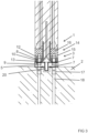
- the connecting step includes, as illustrated in figures 1 to 7 , providing repeatably openable and closable mechanical connection means 3 comprising anchor bolts 8 extending from said another construction element 2.
- the connection step includes screwing first nuts 9 on the anchor bolts 8 so that the nuts are at a distance from said another construction element 2, as illustrated in figures 1 to 3 .
- the connection step includes arranging the anchor bolts 8 to penetrate openings 10 in the prefabricated construction element 1 so that the first nuts 9 are between said another construction element 2 and the prefabricated construction element 1 and a grouting space 11 is formed between said another construction element 2 and the prefabricated construction element 1.
- the connection step includes screwing second nuts 12 to the anchor bolts 8 to secure the prefabricated construction element 1 to the anchor bolts 8.
- a washer 17 is arranged at the anchor bolts 8 between the openings 10 and second nuts 12.
- the method includes preferably, but not necessarily, arranging in the connection step the anchor bolts 8 to penetrate openings 10 formed in metal plates 13 of connector elements 14 at least partly cast into the concrete of the prefabricated construction element 1.
- connector element 14 can for example be in the form of a column shoe, as illustrated in the embodiments shown in figures 1 to 3 , a beam shoe, as illustrated in the embodiment illustrated in figure 7 , or a wall shoe, as illustrated in the embodiments shown in figures 4 and 5 , depending on the form of the prefabricated construction element 1.
- connection step includes arranging the anchor bolts 8 to penetrate openings 10 in the prefabricated construction element 1 so that the anchor bolts 8 extend into a cavity 15 in the prefabricated construction element 1, and the connection step includes screwing said second nuts 12 to the anchor bolts 8 inside the cavities so that the second nuts 12 will be housed in the cavities.
- the method includes a filling step for filling the cavities at least partly with other material 16 than grout 5 prior said grouting step to at least partly prevent grout 5 from entering said cavities.
- At least one of mineral wool, gypsum, plaster and lime mortar is used as said other material 16 in the filling step. These materials are easier to remove than concrete or mortar so that the repeatably openable and closable mechanical connection means 3 can be accessed in the cavity 15 and be opened, as exemplified in figure 8 .
- the method can include providing the prefabricated construction element 1 with at least one of a projection formation 20 configured to project into grout 5 in the joint between the prefabricated construction element 1 and said another construction element 2 and a cavity formation 21 into which grout 5 from the joint between the prefabricated construction element 1 and said another construction element 2 is configured to project.
- the method can include providing said another construction element 2 with at least one of a projection formation 20 configured to project into grout 5 in the joint between the prefabricated construction element 1 and said another construction element 2, and a cavity formation 21 into which grout 5 from the joint between the prefabricated construction element 1 and said another construction element 2 is configured to project.
- the construction element 1 can be provided with a formation 20 that extend into a cavity 21 in the grout 5 between the prefabricated construction element 1 and said another construction element 2, as illustrated in figure 2 .
- construction element 1 can alternatively be provided with a formation 20 that extend into a cavity 21 in said another construction element 2, as illustrated in figure 3 .
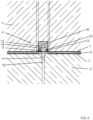
- shear force transfer capacity between the prefabricated construction element 1 and said another construction element 2 be increased, while still creating an easily dismountable connection allowing reuse of a least the construction element 1, by forming a cavity 21 in the surface 6 of the prefabricated construction element 1 so that the cavity 21 is configured to be filled with the grout 5 cast between the prefabricated construction element 1 and said another construction element 2, as illustrated in figure 5 .
- shear force transfer capacity between the prefabricated construction element 1 and said another construction element 2 be increased, while still creating an easily dismountable connection allowing reuse of a least the construction element 1, by forming a cavity 21 both in the surface 6 of the prefabricated construction element 1 and in the surface 6 of said another construction element so that both cavities 21 are configured to be filled with the grout 5 cast between the prefabricated construction element 1 and said another construction element 2, as illustrated in figure 6 .
- the anchor bolts 8 are preferably, but not necessarily, threaded bars, which are screwed into threaded muffs 17, which are casted into concrete of said another construction element 2 so that the threaded muffs 17 extend from the surface 6 of said another construction element 2 into said another construction element 2, and which are anchored by means of anchoring means 18 fastened to said threaded muffs 17 and also casted into concrete of said another construction element 2.
- An example of such is Copra ® anchoring coupler by Peikko Group.
- the prefabricated construction element 1 comprising concrete can for example be any one of a prefabricated reinforced concrete column/pile/pillar, as illustrated in figures 1 to 3 , a prefabricated reinforced concrete beam, as illustrated in figure 7 , and a prefabricated concrete wall element, as illustrated in figures 4 to 6 .
- Said another construction element 2 can also be a prefabricated construction element 1 comprising concrete for example a prefabricated reinforced concrete column/pile/pillar, as illustrated in figure 7 .
- said another construction element 2 can be a cast-in-situ construction element comprising concrete such as a reinforced concrete foundation or a part belonging to a reinforced concrete foundation, as illustrated in figures 1 to 6 .
- the prefabricated construction element 1 is connected by means of repeatably openable and closable mechanical connection means 3 to said another construction element 2 so that a joint 4 is formed between the prefabricated construction element 1 and said another construction element 2 and so that the joint 4 is at least partly limited by the prefabricated construction element 1 and said another construction element 2.
- the joint 4 is at least partly covered such as filled with grout 5 that is allowed to harden.
- separation means 7 such as anti-adhesion means 7 is present between surfaces 6 of the prefabricated construction element 1 that is at least partly covered by grout 5 and said grout 5 at least partly covering the joint 4 and that allowed to harden.
- the separation means 7 can comprise mechanical anti-adhesion means such as perforated or unperforated plates, sheets or films.
- Mechanical anti-adhesion means can for example be an expanded steel sheet, a perforated steel sheet, a plate of polymer, a sheet of polymer, a film of polymer, a textile sheet, a fabric sheet, formwork liner, and wood such as coated plywood.
- An advantage that is achieved by using a perforated plate, sheet or a film as a separation means 7 is that the perforations allows for grout 5 to attach to the prefabricated construction element 1 through the separation means 7. This provides for a stronger connection between the grout 5 and the prefabricated construction element 1 while allowing for easy detaching of the prefabricated construction element 1 from the separation means 7 and from the grout 5.
- the separation means 7 can comprise anti-adhesion substances such as fluid for example oil or carbon.
- the separation means 7 is preferably, but not necessarily, a means separate from the prefabricated construction element 1, i.e. not a part of the prefabricated construction element, and a means separate from said another construction element 2, i.e. not a part of said another construction element 2.
- the separation means 7 follows preferably, but not necessarily, at least partly an interface (not marked with a reference numeral) i.e. a connection surface between the grout 5 that covers the prefabricated construction element 1 in the joint 4 and the surfaces 6 of the prefabricated construction element 1.
- connection arrangement allows easy removal of the prefabricated construction element 1 from grouting without damaging the prefabricated construction element 1, because the grout 5 will not adhere to the surfaces 6 of the prefabricated construction element 1 coated by anti-adhesion substance 7.
- separation means 7 such as any alternative of the separation means 7 as presented is preferably also present between surfaces 6 of said another construction element 2 that is at least partly covered by grout 5 and said grout 5 at least partly covering the joint 4 and that is allowed to harden.
- An advantage of this is that this allows easy removal of the grouting from the other construction element, because the grout 5 will not adhere to the surfaces 6 of said another construction element 2 coated by anti-adhesion substance 7.
- the separation means 7 follows preferably, but not necessarily, at least partly an interface (not marked with a reference numeral) i.e. a connection surface between the grout 5 that covers said another construction element 2 in the joint 4 and the surfaces 6 of said another construction element 2.
- connection arrangement includes, as illustrated in figures 1 to 7 , repeatably openable and closable mechanical connection means 3 comprising anchor bolts 8 extending from said another construction element 2.
- the repeatably openable and closable mechanical connection means 3 include first nuts 9 screwed on the anchor bolts 8 so that the nuts are at a distance from said another construction element 2, as illustrated in figures 1 to 3 .
- the anchor bolts 8 can penetrate openings 10 in the prefabricated construction element 1 so that the first nuts 9 are between said another construction element 2 and the prefabricated construction element 1 and so that a grouting space 11 is formed between said another construction element 2 and the prefabricated construction element 1.
- the repeatably openable and closable mechanical connection means 3 include second nuts 12 screwed to the anchor bolts 8 to secure the prefabricated construction element 1 to the anchor bolts 8.
- a washer 17 is arranged at the anchor bolts 8 between the openings 10 and second nuts 12.
- the anchor bolts 8 can penetrate openings 10 formed in metal plates 13 of connector elements 14 at least partly cast into the concrete of the prefabricated construction element 1.
- Such connector element 14 can for example be in the form of a column shoe, as illustrated in the embodiments shown in figures 1 to 3 , a beam shoe, as illustrated in the embodiment illustrated in figure 7 , or a wall shoe, as illustrated in the embodiments shown in figures 4 and 5 , depending on the form of the prefabricated construction element 1.
- the anchor bolts 8 penetrate in the connection arrangement openings 10 in the prefabricated construction element 1 so that the anchor bolts 8 extend into a cavity 15 in the prefabricated construction element 1, and said second nuts 12 are screwed to the anchor bolts 8 inside the cavities so that the second nuts 12 are housed in the cavities.
- the cavities are at least partly with other material 16 than grout 5 prior said grouting step to at least partly prevent grout 5 from entering said cavities.
- At least one of mineral wool, gypsum, plaster and lime mortar are used as said other material 16 in the filling step. These materials are easier to remove than concrete or mortar so that the repeatably openable and closable mechanical connection means 3 can be accessed in the cavity 15 and be opened, as exemplified in figure 8 .
- the prefabricated construction element 1 can be provided with at least one of a projection formation 20 that projects into grout 5 in the joint between the prefabricated construction element 1 and said another construction element 2 and a cavity formation 21 into which grout 5 from the joint between the prefabricated construction element 1 and said another construction element 2 projects.
- said another construction element 2 can be provided with at least one of a projection formation 20 that projects into grout 5 in the joint between the prefabricated construction element 1 and said another construction element 2, and a cavity formation 21 into which grout 5 from the joint between the prefabricated construction element 1 and said another construction element 2 projects.
- the construction element 1 can be provided with a formation 20 that extend into a cavity 21 in the grout 5 between the prefabricated construction element 1 and said another construction element 2, as illustrated in figure 2 .
- construction element 1 can alternatively be provided with a formation 20 that extend into a cavity 21 in said another construction element 2, as illustrated in figure 3 .
- shear force transfer capacity between the prefabricated construction element 1 and said another construction element 2 be increased, while still creating an easily dismountable connection allowing reuse of a least the construction element 1, by forming a cavity 21 in the surface 6 of the prefabricated construction element 1 so that the cavity 21 is configured to be filled with the grout 5 cast between the prefabricated construction element 1 and said another construction element 2, as illustrated in figure 5 .
- shear force transfer capacity between the prefabricated construction element 1 and said another construction element 2 be increased, while still creating an easily dismountable connection allowing reuse of a least the construction element 1, by forming a cavity 21 both in the surface 6 of the prefabricated construction element 1 and in the surface 6 of said another construction element so that both cavities 21 are configured to be filled with the grout 5 cast between the prefabricated construction element 1 and said another construction element 2, as illustrated in figure 6 .
- the anchor bolts 8 are preferably, but not necessarily, threaded bars, which are screwed into threaded muffs 17, which are casted into concrete of said another construction element 2 so that the threaded muffs 17 extend from the surface 6 of said another construction element 2 into said another construction element 2, and which are anchored by means of anchoring means 18 fastened to said threaded muffs 17 and also casted into concrete of said another construction element 2.
- An example of such is Copra ® anchoring coupler by Peikko Group.
Description
- The invention relates to method for mounting a prefabricated construction element comprising concrete to another construction element as defined in the preamble of
independent claim 1. - The invention also relates to a connection arrangement between prefabricated construction element comprising concrete and another construction element as defined in the preamble of
independent claim 9 - Document
ITVR 20 100 206 A1 claim 1 and a connection arrangement according to the preamble ofclaim 9. - The object is to provide a method for mounting a prefabricated construction element comprising concrete to another construction element and a connection arrangement between prefabricated construction element comprising concrete and another construction element, which allows to open the connection between the prefabricated construction and the another construction element in such manner that the prefabricated construction element comprising concrete can easily be demounted and be reused so as to promote circular economy.
- The method for mounting a prefabricated construction element comprising concrete to another construction element of the invention is characterized by the definitions of
independent claim 1. - Preferred embodiments of the method are defined in the
dependent claims 2 to 8. - The connection arrangement between prefabricated construction element comprising concrete and another construction element of the invention is correspondingly characterized by the definitions of
independent claim 9 . - Preferred embodiments of the connection arrangement are defined in the dependent claims 10-16.
- The prefabricated construction element comprising concrete can for example be any one of a prefabricated reinforced concrete column/pile/pillar, a prefabricated reinforced concrete beam and a prefabricated concrete wall element.
- Said another construction element can also be a prefabricated construction element comprising concrete for example a prefabricated reinforced concrete column/pile/pillar. Alternatively said another construction element can be a cast-in-situ construction element comprising concrete such as a reinforced concrete foundation or a part belonging to a reinforced concrete foundation.
- In the following the method and the connection arrangement will described in more detail by referring to the figures, which
-
Figure 1 shows a first embodiment of the connection arrangement, where the prefabricated construction element is in the form of a prefabricated reinforced concrete column and where the another construction element is in the form of reinforced concrete foundation, -
Figure 2 shows a second embodiment of the connection arrangement, where the prefabricated construction element is in the form of a prefabricated reinforced concrete column and where the another construction element is in the form of reinforced concrete foundation, -
Figure 3 shows a third embodiment of the connection arrangement, where the prefabricated construction element is in the form of a prefabricated reinforced concrete column and where the another construction element is in the form of reinforced concrete foundation, -
Figure 4 shows a fourth embodiment of the connection arrangement, where the prefabricated construction element is in the form of a prefabricated concrete wall element and where the another construction element is in the form of reinforced concrete foundation, -
Figure 5 shows a fifth embodiment of the connection arrangement, where the prefabricated construction element is in the form of a prefabricated concrete wall element and where the another construction element is in the form of reinforced concrete foundation, -
Figure 6 shows a sixth embodiment of the connection arrangement, where the prefabricated construction element is in the form of a prefabricated concrete wall element and where the another construction element is in the form of reinforced concrete foundation, -
Figure 7 shows a seventh embodiment of the connection arrangement, where the prefabricated construction element is in the form of a prefabricated concrete beam and where the another construction element is in the form of prefabricated reinforced concrete column, -
Figure 8 shows a step in a demounting process of the first embodiment of the connection arrangement shown infigure 1 , -
Figure 9 shows another step in the demounting process of the first embodiment of the connection arrangement shown infigure 1 , -
Figure 10 shows still another step in the demounting process of the first embodiment of the connection arrangement shown infigure 1 , -
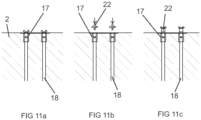
Figures 11a to 11c shows further steps of the demounting process of the first embodiment of the connection arrangement shown infigure 1 , -
Figure 12 shows a separation means that is in the form of a non-perforated sheet, and -
Figure 13 shows a separation means that is in the form of an expanded steel sheet. - First the method for mounting a
prefabricated construction element 1 comprising concrete to anotherconstruction element 2 will be described in greater detail. - The
prefabricated construction element 1 comprising concrete can for example be any one of a prefabricated reinforced concrete column/pile/pillar, as illustrated infigures 1 to 3 , a prefabricated reinforced concrete beam, as illustrated infigure 7 , and a prefabricated concrete wall element, as illustrated infigures 4 to 6 . - Said another
construction element 2 can also be aprefabricated construction element 1 comprising concrete for example a prefabricated reinforced concrete column/pile/pillar, as illustrated infigure 7 . Alternatively said anotherconstruction element 2 can be a cast-in-situ construction element comprising concrete such as a reinforced concrete foundation or a part belonging to a reinforced concrete foundation, as illustrated infigures 1 to 6 . - The method comprises a connecting step for connecting the
prefabricated construction element 1 by means of repeatably openable and closable mechanical connection means 3 to said anotherconstruction element 2 so that a joint 4 is formed between theprefabricated construction element 1 and said anotherconstruction element 2 and so that the joint 4 is at least partly limited by theprefabricated construction element 1 and said anotherconstruction element 2. - The method comprises a grouting step for grouting the joint 4 by covering such as filling the joint 4 at least partly with
grout 5 and allowing thegrout 5 to harden. - The method comprises a coating step for
coating surfaces 6 of theprefabricated construction element 1 that is to be covered bygrout 5 in said grouting step at least partly with separation means 7 such as with anti-adhesion means prior said grouting step. - In the coating step can mechanical anti-adhesion means such as perforated or unperforated plates, sheets or films be used as separation means 7. As mechanical anti-adhesion means can for example be used an expanded steel sheet, a perforated steel sheet, a plate of polymer, a sheet of polymer, a film of polymer, a textile sheet, a fabric sheet, formwork liner, and wood such as coated plywood. An advantage that is achieved by using a perforated plate, sheet or a film as a separation means 7 is that the perforations allows for
grout 5 to attach to theprefabricated construction element 1 through the separation means 7. This provides for a stronger connection between thegrout 5 and theprefabricated construction element 1 while allowing for easy detaching of theprefabricated construction element 1 from the separation means 7 and from thegrout 5. - In the coating step can anti-adhesion substances such as fluid for example oil, cementitious retarder, or carbon be used as separation means 7.
- The coating step includes preferably, but not necessarily, providing for the coating step a separation means 7 that is a means separate from the
prefabricated construction element 1, i.e. that does not form a part of theprefabricated construction element 1, and that is a means separate from said anotherconstruction element 2, i.e. that does not form a part of said anotherconstruction element 2. - The separation means 7 is preferably, but not necessarily, arranged to at least partly follow an interface (not marked with a reference numeral) i.e. a connection surface between the
grout 5 that is configured to cover theprefabricated construction element 1 in the joint 4 and thesurfaces 6 of theprefabricated construction element 1. - The method allows easy removal of the
prefabricated construction element 1 from grouting without damaging theprefabricated construction element 1, because thegrout 5 will not adhere to thesurfaces 6 of theprefabricated construction element 1 because of the separation means 7. - The coating step includes preferably, but not necessarily, additionally
coating surfaces 6 of said anotherconstruction element 2 that is to be covered bygrout 5 at least partly with separation means 7 such as with any alternative of the separation means 7 presented prior said grouting. In such case, the separation means 7 is preferably, but not necessarily, arranged to at least partly follow an interface (not marked with a reference numeral) i.e. a connection surface between thegrout 5 that is configured to cover said anotherconstruction element 2 in the joint 4 and thesurfaces 6 of said anotherconstruction element 2. - The method allows easy removal of the from the said another
construction element 2 without damaging said anotherconstruction element 2, because thegrout 5 will not adhere to thesurfaces 6 of said anotherconstruction element 2 coated by separation means 7. - According to the invention, the connecting step includes, as illustrated in
figures 1 to 7 , providing repeatably openable and closable mechanical connection means 3 comprisinganchor bolts 8 extending from said anotherconstruction element 2. The connection step includes screwingfirst nuts 9 on theanchor bolts 8 so that the nuts are at a distance from said anotherconstruction element 2, as illustrated infigures 1 to 3 . The connection step includes arranging theanchor bolts 8 to penetrateopenings 10 in theprefabricated construction element 1 so that thefirst nuts 9 are between said anotherconstruction element 2 and theprefabricated construction element 1 and agrouting space 11 is formed between said anotherconstruction element 2 and theprefabricated construction element 1. The connection step includes screwingsecond nuts 12 to theanchor bolts 8 to secure theprefabricated construction element 1 to theanchor bolts 8. The embodiments illustrated infigures 4 to 6 , awasher 17 is arranged at theanchor bolts 8 between theopenings 10 andsecond nuts 12. In such embodiments, the method includes preferably, but not necessarily, arranging in the connection step theanchor bolts 8 to penetrateopenings 10 formed inmetal plates 13 ofconnector elements 14 at least partly cast into the concrete of theprefabricated construction element 1.Such connector element 14 can for example be in the form of a column shoe, as illustrated in the embodiments shown infigures 1 to 3 , a beam shoe, as illustrated in the embodiment illustrated infigure 7 , or a wall shoe, as illustrated in the embodiments shown infigures 4 and5 , depending on the form of theprefabricated construction element 1. The connection step includes arranging theanchor bolts 8 to penetrateopenings 10 in theprefabricated construction element 1 so that theanchor bolts 8 extend into acavity 15 in theprefabricated construction element 1, and the connection step includes screwing saidsecond nuts 12 to theanchor bolts 8 inside the cavities so that thesecond nuts 12 will be housed in the cavities. According to the invention, the method includes a filling step for filling the cavities at least partly withother material 16 thangrout 5 prior said grouting step to at least partly preventgrout 5 from entering said cavities. At least one of mineral wool, gypsum, plaster and lime mortar is used as saidother material 16 in the filling step. These materials are easier to remove than concrete or mortar so that the repeatably openable and closable mechanical connection means 3 can be accessed in thecavity 15 and be opened, as exemplified infigure 8 . - To increase the shear force transfer capacity between
grout 5 in the joint 4 between theprefabricated construction element 1 and said anotherconstruction element 2, while still creating an easily dismountable connection allowing reuse of a least theconstruction element 1, the method can include providing theprefabricated construction element 1 with at least one of aprojection formation 20 configured to project intogrout 5 in the joint between theprefabricated construction element 1 and said anotherconstruction element 2 and acavity formation 21 into whichgrout 5 from the joint between theprefabricated construction element 1 and said anotherconstruction element 2 is configured to project. - To increase the shear force transfer capacity between
grout 5 in the joint 4 between theprefabricated construction element 1 and said anotherconstruction element 2, while still creating an easily dismountable connection allowing reuse of a least theconstruction element 1, the method can include providing said anotherconstruction element 2 with at least one of aprojection formation 20 configured to project intogrout 5 in the joint between theprefabricated construction element 1 and said anotherconstruction element 2, and acavity formation 21 into whichgrout 5 from the joint between theprefabricated construction element 1 and said anotherconstruction element 2 is configured to project. - To increase the shear force transfer capacity between the
prefabricated construction element 1 and said anotherconstruction element 2, while still creating an easily dismountable connection allowing reuse of a least theconstruction element 1, theconstruction element 1 can be provided with aformation 20 that extend into acavity 21 in thegrout 5 between theprefabricated construction element 1 and said anotherconstruction element 2, as illustrated infigure 2 . - To increase the shear force transfer capacity between the
prefabricated construction element 1 and said anotherconstruction element 2, while still creating an easily dismountable connection allowing reuse of a least theconstruction element 1,construction element 1 can alternatively be provided with aformation 20 that extend into acavity 21 in said anotherconstruction element 2, as illustrated infigure 3 . - Alternatively can shear force transfer capacity between the
prefabricated construction element 1 and said anotherconstruction element 2 be increased, while still creating an easily dismountable connection allowing reuse of a least theconstruction element 1, by forming acavity 21 in thesurface 6 of theprefabricated construction element 1 so that thecavity 21 is configured to be filled with thegrout 5 cast between theprefabricated construction element 1 and said anotherconstruction element 2, as illustrated infigure 5 . - Alternatively can shear force transfer capacity between the
prefabricated construction element 1 and said anotherconstruction element 2 be increased, while still creating an easily dismountable connection allowing reuse of a least theconstruction element 1, by forming acavity 21 both in thesurface 6 of theprefabricated construction element 1 and in thesurface 6 of said another construction element so that bothcavities 21 are configured to be filled with thegrout 5 cast between theprefabricated construction element 1 and said anotherconstruction element 2, as illustrated infigure 6 . - The
anchor bolts 8 are preferably, but not necessarily, threaded bars, which are screwed into threadedmuffs 17, which are casted into concrete of said anotherconstruction element 2 so that the threaded muffs 17 extend from thesurface 6 of said anotherconstruction element 2 into said anotherconstruction element 2, and which are anchored by means of anchoring means 18 fastened to said threaded muffs 17 and also casted into concrete of said anotherconstruction element 2. An example of such is Copra® anchoring coupler by Peikko Group. An advantage of this that this allows to remove the threaded bar from the threadedmuff 17 so that noanchor bolts 8 project from said anotherconstruction element 2 as illustrated infigures 11a to 11c . Infigures 11b and 11c aseparate tool 22 is screwed into the treaded muffs 17 to remove the treaded muffs 17 from the anotherconstruction element 2. - Next the connection arrangement between
prefabricated construction element 1 comprising concrete and anotherconstruction element 2 will be described in greater detail. - The
prefabricated construction element 1 comprising concrete can for example be any one of a prefabricated reinforced concrete column/pile/pillar, as illustrated infigures 1 to 3 , a prefabricated reinforced concrete beam, as illustrated infigure 7 , and a prefabricated concrete wall element, as illustrated infigures 4 to 6 . - Said another
construction element 2 can also be aprefabricated construction element 1 comprising concrete for example a prefabricated reinforced concrete column/pile/pillar, as illustrated infigure 7 . Alternatively said anotherconstruction element 2 can be a cast-in-situ construction element comprising concrete such as a reinforced concrete foundation or a part belonging to a reinforced concrete foundation, as illustrated infigures 1 to 6 . - In the connection arrangement, the
prefabricated construction element 1 is connected by means of repeatably openable and closable mechanical connection means 3 to said anotherconstruction element 2 so that a joint 4 is formed between theprefabricated construction element 1 and said anotherconstruction element 2 and so that the joint 4 is at least partly limited by theprefabricated construction element 1 and said anotherconstruction element 2. - In the connection arrangement, the joint 4 is at least partly covered such as filled with
grout 5 that is allowed to harden. - In the connection arrangement, separation means 7 such as anti-adhesion means 7 is present between
surfaces 6 of theprefabricated construction element 1 that is at least partly covered bygrout 5 and saidgrout 5 at least partly covering the joint 4 and that allowed to harden. - The separation means 7 can comprise mechanical anti-adhesion means such as perforated or unperforated plates, sheets or films. Mechanical anti-adhesion means can for example be an expanded steel sheet, a perforated steel sheet, a plate of polymer, a sheet of polymer, a film of polymer, a textile sheet, a fabric sheet, formwork liner, and wood such as coated plywood. An advantage that is achieved by using a perforated plate, sheet or a film as a separation means 7 is that the perforations allows for
grout 5 to attach to theprefabricated construction element 1 through the separation means 7. This provides for a stronger connection between thegrout 5 and theprefabricated construction element 1 while allowing for easy detaching of theprefabricated construction element 1 from the separation means 7 and from thegrout 5. - The separation means 7 can comprise anti-adhesion substances such as fluid for example oil or carbon.
- The separation means 7 is preferably, but not necessarily, a means separate from the
prefabricated construction element 1, i.e. not a part of the prefabricated construction element, and a means separate from said anotherconstruction element 2, i.e. not a part of said anotherconstruction element 2. - The separation means 7 follows preferably, but not necessarily, at least partly an interface (not marked with a reference numeral) i.e. a connection surface between the
grout 5 that covers theprefabricated construction element 1 in the joint 4 and thesurfaces 6 of theprefabricated construction element 1. - The connection arrangement allows easy removal of the
prefabricated construction element 1 from grouting without damaging theprefabricated construction element 1, because thegrout 5 will not adhere to thesurfaces 6 of theprefabricated construction element 1 coated byanti-adhesion substance 7. - In the connection arrangement, separation means 7 such as any alternative of the separation means 7 as presented is preferably also present between
surfaces 6 of said anotherconstruction element 2 that is at least partly covered bygrout 5 and saidgrout 5 at least partly covering the joint 4 and that is allowed to harden. An advantage of this is that this allows easy removal of the grouting from the other construction element, because thegrout 5 will not adhere to thesurfaces 6 of said anotherconstruction element 2 coated byanti-adhesion substance 7. In such case, the separation means 7 follows preferably, but not necessarily, at least partly an interface (not marked with a reference numeral) i.e. a connection surface between thegrout 5 that covers said anotherconstruction element 2 in the joint 4 and thesurfaces 6 of said anotherconstruction element 2. - According to the invention, the connection arrangement includes, as illustrated in
figures 1 to 7 , repeatably openable and closable mechanical connection means 3 comprisinganchor bolts 8 extending from said anotherconstruction element 2. The repeatably openable and closable mechanical connection means 3 includefirst nuts 9 screwed on theanchor bolts 8 so that the nuts are at a distance from said anotherconstruction element 2, as illustrated infigures 1 to 3 . Theanchor bolts 8 can penetrateopenings 10 in theprefabricated construction element 1 so that thefirst nuts 9 are between said anotherconstruction element 2 and theprefabricated construction element 1 and so that agrouting space 11 is formed between said anotherconstruction element 2 and theprefabricated construction element 1. The repeatably openable and closable mechanical connection means 3 includesecond nuts 12 screwed to theanchor bolts 8 to secure theprefabricated construction element 1 to theanchor bolts 8. The embodiments illustrated infigures 4 to 6 , awasher 17 is arranged at theanchor bolts 8 between theopenings 10 and second nuts 12. In such embodiments, theanchor bolts 8 can penetrateopenings 10 formed inmetal plates 13 ofconnector elements 14 at least partly cast into the concrete of theprefabricated construction element 1.Such connector element 14 can for example be in the form of a column shoe, as illustrated in the embodiments shown infigures 1 to 3 , a beam shoe, as illustrated in the embodiment illustrated infigure 7 , or a wall shoe, as illustrated in the embodiments shown infigures 4 and5 , depending on the form of theprefabricated construction element 1. Theanchor bolts 8 penetrate in theconnection arrangement openings 10 in theprefabricated construction element 1 so that theanchor bolts 8 extend into acavity 15 in theprefabricated construction element 1, and saidsecond nuts 12 are screwed to theanchor bolts 8 inside the cavities so that the second nuts 12 are housed in the cavities. The cavities are at least partly withother material 16 thangrout 5 prior said grouting step to at least partly preventgrout 5 from entering said cavities. At least one of mineral wool, gypsum, plaster and lime mortar are used as saidother material 16 in the filling step. These materials are easier to remove than concrete or mortar so that the repeatably openable and closable mechanical connection means 3 can be accessed in thecavity 15 and be opened, as exemplified infigure 8 . - To increase the shear force transfer capacity between
grout 5 in the joint 4 between theprefabricated construction element 1 and said anotherconstruction element 2, while still creating an easily dismountable connection allowing reuse of a least theconstruction element 1, theprefabricated construction element 1 can be provided with at least one of aprojection formation 20 that projects intogrout 5 in the joint between theprefabricated construction element 1 and said anotherconstruction element 2 and acavity formation 21 into whichgrout 5 from the joint between theprefabricated construction element 1 and said anotherconstruction element 2 projects. - To increase the shear force transfer capacity between
grout 5 in the joint 4 between theprefabricated construction element 1 and said anotherconstruction element 2, while still creating an easily dismountable connection allowing reuse of a least theconstruction element 1, said anotherconstruction element 2 can be provided with at least one of aprojection formation 20 that projects intogrout 5 in the joint between theprefabricated construction element 1 and said anotherconstruction element 2, and acavity formation 21 into whichgrout 5 from the joint between theprefabricated construction element 1 and said anotherconstruction element 2 projects. - To increase the shear force transfer capacity between the
prefabricated construction element 1 and said anotherconstruction element 2, while still creating an easily dismountable connection allowing reuse of a least theconstruction element 1, theconstruction element 1 can be provided with aformation 20 that extend into acavity 21 in thegrout 5 between theprefabricated construction element 1 and said anotherconstruction element 2, as illustrated infigure 2 . - To increase the shear force transfer capacity between the
prefabricated construction element 1 and said anotherconstruction element 2, while still creating an easily dismountable connection allowing reuse of a least theconstruction element 1,construction element 1 can alternatively be provided with aformation 20 that extend into acavity 21 in said anotherconstruction element 2, as illustrated infigure 3 . - Alternatively can shear force transfer capacity between the
prefabricated construction element 1 and said anotherconstruction element 2 be increased, while still creating an easily dismountable connection allowing reuse of a least theconstruction element 1, by forming acavity 21 in thesurface 6 of theprefabricated construction element 1 so that thecavity 21 is configured to be filled with thegrout 5 cast between theprefabricated construction element 1 and said anotherconstruction element 2, as illustrated infigure 5 . - Alternatively can shear force transfer capacity between the
prefabricated construction element 1 and said anotherconstruction element 2 be increased, while still creating an easily dismountable connection allowing reuse of a least theconstruction element 1, by forming acavity 21 both in thesurface 6 of theprefabricated construction element 1 and in thesurface 6 of said another construction element so that bothcavities 21 are configured to be filled with thegrout 5 cast between theprefabricated construction element 1 and said anotherconstruction element 2, as illustrated infigure 6 . - The
anchor bolts 8 are preferably, but not necessarily, threaded bars, which are screwed into threadedmuffs 17, which are casted into concrete of said anotherconstruction element 2 so that the threaded muffs 17 extend from thesurface 6 of said anotherconstruction element 2 into said anotherconstruction element 2, and which are anchored by means of anchoring means 18 fastened to said threaded muffs 17 and also casted into concrete of said anotherconstruction element 2. An example of such is Copra® anchoring coupler by Peikko Group. An advantage of this that this allows to remove the threaded bar from the threadedmuff 17 so that noanchor bolts 8 project from said anotherconstruction element 2 as illustrated infigures 11a to 11c . Infigures 11b and 11c aseparate tool 22 is screwed into the treaded muffs 17 to remove the treaded muffs 17 from the anotherconstruction element 2. - It is apparent to a person skilled in the art that as technology advanced, the basic idea of the invention can be implemented in various ways. The invention and its embodiments are therefore not restricted to the above examples, but they may vary within the scope of the claims.
Claims (16)
- A method for mounting a prefabricated construction element (1) comprising concrete to another construction element (2), wherein the method comprisesa connecting step for connecting the prefabricated construction element (1) by means of repeatably openable and closable mechanical connection means (3) to said another construction element (2) so that a joint (4) is formed between the prefabricated construction element (1) and said another construction element (2),a grouting step for grouting the joint (4) by covering the joint (4) at least partly with grout (5) and allowing the grout (5) to harden, anda coating step for coating surfaces (6) of the prefabricated construction element (1) that is to be covered by grout (5) in said grouting step at least partly with separation means (7) prior said grouting step,wherein the connecting step includes providing repeatably openable and closable mechanical connection means (3) comprising anchor bolts (8) extending from said another construction element (2),wherein the connection step includes screwing first nuts (9) on the anchor bolts (8) so that the nuts are at a distance from said another construction element (2),wherein the connection step includes arranging the anchor bolts (8) to penetrate openings (10) in the prefabricated construction element (1) so that the first nuts (9) are between said another construction element (2) and the prefabricated construction element (1) and a grouting space (11) is formed between said another construction element (2) and the prefabricated construction element (1),wherein the connection step includes screwing second nuts (12) to the anchor bolts (8) to secure the prefabricated construction element (1) to the anchor bolts (8).wherein the connection step includes arranging the anchor bolts (8) to penetrate openings (10) in the prefabricated construction element (1) so that the anchor bolts (8) extend into a cavity (15) in the prefabricated construction element (1),wherein the connection step includes screwing said second nuts (12) to the anchor bolts (8) inside the cavities so that the second nuts (12) will be housed in the cavities,characterizedby a filling step for filling the cavities at least partly with other material (16) than grout (5) prior said grouting step to at least partly prevent grout (5) from entering said cavities, andby using at least one of mineral wool, gypsum, plaster and lime mortar as said other material (16) in the filling step.
- The method according to claim 1, characterized
by the separation means (7) is arranged to at least partly follow an interface between the grout (5) that is configured to cover the prefabricated construction element (1) in the joint (4) and the prefabricated construction element (1). - The method according to claim 1 or 2, characterized
by the coating step includes additionally coating surfaces (6) of said another construction element (2) that is to be covered by grout (5) at least partly with separation means (7) prior said grouting. - The method according to claim 3, characterized
by the separation means (7) is arranged to at least partly follow an interface between the grout (5) that is configured to cover said another construction element (2) in the joint (4) and said another construction element (2). - The method according to any of the claims 1 to 4, characterized
by providing as anchor bolts (8) threaded bars, which are screwed into threaded muffs (17), which are casted into concrete of said another construction element (2) so that the threaded muffs (17) extend from the surface (6) of said another construction element (2) into said another construction element (2), and which are anchored by means of anchoring means (18) fastened to said threaded muffs (17) and also casted into concrete of said another construction element (2). - The method according to any of the claims 1 to 5, characterized
by providing for the coating step a separation means (7) that is a means separate from the prefabricated construction element (1) and that is a means separate from said another construction element (2). - The method according to any of the claims 1 to 6, characterized
by providing the prefabricated construction element (1) with at least one of a projection formation (20) configured to project into grout (5) in the joint between the prefabricated construction element (1) and said another construction element (2) and a cavity formation (21) into which grout (5) from the joint between the prefabricated construction element (1) and said another construction element (2) is configured to project. - The method according to any of the claims 1 to 7, characterized
by providing said another construction element (2) with at least one of a projection formation (20) configured to project into grout (5) in the joint between the prefabricated construction element (1) and said another construction element (2), and a cavity formation (21) into which grout (5) from the joint between the prefabricated construction element (1) and said another construction element (2) is configured to project. - A connection arrangement between prefabricated construction element (1) comprising concrete and another construction element (2), wherein in the connection arrangementthe prefabricated construction element (1) is connected by means of repeatably openable and closable mechanical connection means (3) to said another construction element (2) so that a joint (4) is formed between the prefabricated construction element (1) and said another construction element (2), andthe joint (4) is at least partly covered with grout (5) that is allowed to harden,by separation means (7) between surfaces (6) of the prefabricated construction element (1) that is at least partly covered by grout (5) and said grout (5) at least partly covering the joint (4) and that allowed to hardenby said repeatably openable and closable mechanical connection means (3) comprising anchor bolts (8) extending from said another construction element (2),by first nuts (9) screwed on the anchor bolts (8) so that the nuts are at a distance from said another construction element (2),by the anchor bolts (8) penetrating openings (10) in the prefabricated construction element (1) so that the first nuts (9) are between said another construction element (2) and the prefabricated construction element (1) and a grouting space (11) is formed between said another construction element (2) and the prefabricated construction element (1), andby second nuts (12) screwed to the anchor bolts (8) to secure the prefabricated construction element (1) to the anchor bolts (8)by the anchor bolts (8) penetrate the openings (10) in the prefabricated construction element (1) so that the anchor bolts (8) extend into a cavity (15) in the prefabricated construction element (1), andby the said second nuts (12) being screwed to the anchor bolts (8) inside the cavities so that the second nuts (12) are housed in the cavities,characterizedby the cavities being at least partly filled with other material (16) than grout (5) to at least partly prevent grout (5) from entering said cavities, andby said other material (16) comprising at least one of mineral wool, gypsum, plaster and lime mortar.
- The connection arrangement according to claim 9, characterized
by the separation means (7) follows at least partly an interface between the grout (5) that covers the prefabricated construction element (1) in the joint (4) and the prefabricated construction element (1). - The connection arrangement according to claim 9 or 10, characterized
by separation means (7) between surfaces (6) of said another construction element (2) that is at least partly covered by grout (5) and said grout (5) at least partly covering the joint (4) and that allowed to harden. - The connection arrangement according to any of the claims 9 to 11, characterized
by the separation means (7) follows at least partly an interface between the grout (5) that covers said another construction element (2) in the joint (4) and said another construction element (2). - The connection arrangement according to any of the claims 9 to 12, characterized
by the anchor bolts (8) are threaded bars, which are screwed into threaded muffs (17), which are casted into concrete of said another construction element (2) so that the threaded muffs (17) extend from the surface (6) of said another construction element (2) into said another construction element (2), and which are anchored by means of anchoring means (18) fastened to said threaded muffs (17) and also casted into concrete of said another construction element (2). - The connection arrangement according to any of the claims 9 to 13, characterized
by the separation means (7) is a means separate from the prefabricated construction element (1) and a means separate from said another construction element (2). - The connection arrangement according to any of the claims 9 to 14, characterized
by the prefabricated construction element (1) is provided with at least one of a projection formation (20) that projects into grout (5) in the joint between the prefabricated construction element (1) and said another construction element (2) and a cavity formation (21) into which grout (5) from the joint between the prefabricated construction element (1) and said another construction element (2) projects. - The connection arrangement according to any of the claims 9 to 15, characterized
by said another construction element (2) is provided with at least one of a projection formation (20) that projects into grout (5) in the joint between the prefabricated construction element (1) and said another construction element (2), and a cavity formation (21) into which grout (5) from the joint between the prefabricated construction element (1) and said another construction element (2) projects.
Applications Claiming Priority (2)
| Application Number | Priority Date | Filing Date | Title |
|---|---|---|---|
| FI20195517 | 2019-06-14 | ||
| PCT/FI2020/050363 WO2020249852A1 (en) | 2019-06-14 | 2020-05-29 | Method for mounting a prefabricated construction element to another construction element and connection arrangement |
Publications (3)
| Publication Number | Publication Date |
|---|---|
| EP3983618A1 EP3983618A1 (en) | 2022-04-20 |
| EP3983618C0 EP3983618C0 (en) | 2023-07-26 |
| EP3983618B1 true EP3983618B1 (en) | 2023-07-26 |
Family
ID=71069869
Family Applications (1)
| Application Number | Title | Priority Date | Filing Date |
|---|---|---|---|
| EP20731524.3A Active EP3983618B1 (en) | 2019-06-14 | 2020-05-29 | Method for mounting a prefabricated construction element to another construction element and connection arrangement |
Country Status (7)
| Country | Link |
|---|---|
| EP (1) | EP3983618B1 (en) |
| KR (1) | KR102619755B1 (en) |
| CN (1) | CN114174610B (en) |
| ES (1) | ES2961083T3 (en) |
| HU (1) | HUE063667T2 (en) |
| PL (1) | PL3983618T3 (en) |
| WO (1) | WO2020249852A1 (en) |
Families Citing this family (1)
| Publication number | Priority date | Publication date | Assignee | Title |
|---|---|---|---|---|
| CN114960390A (en) * | 2022-06-01 | 2022-08-30 | 中铁第四勘察设计院集团有限公司 | Pre-embedded type void grouting device and grouting construction method |
Family Cites Families (8)
| Publication number | Priority date | Publication date | Assignee | Title |
|---|---|---|---|---|
| US3775928A (en) * | 1972-03-09 | 1973-12-04 | Descon Concordia Syst Ltd | Erection method for structural system |
| DE102004017006B4 (en) * | 2004-04-02 | 2012-03-29 | Aloys Wobben | Method of erecting a tower |
| DE102004017008B4 (en) * | 2004-04-02 | 2009-10-22 | Aloys Wobben | Method for erecting a tower |
| ITMI20051565A1 (en) * | 2005-08-11 | 2007-02-12 | Edilmatic S R L | INTERCONNECTION DEVICE FOR CONNECTING A BEAM TO A PREFABRICATED PILLAR IN REINFORCED CONCRETE AND METHOD TO CONNECT THE BEAM TO THE PILLAR BY MEANS OF THIS DEVICE |
| US8037651B2 (en) * | 2008-03-19 | 2011-10-18 | Clifford Dent | Ground anchor assembly |
| US20110131899A1 (en) * | 2010-04-30 | 2011-06-09 | Stefan Voss | Apparatus and method for producing a concrete foundation |
| IT1403484B1 (en) * | 2010-10-29 | 2013-10-17 | Sar Costruzioni Prefabbricate S R L | FOUNDATION STRUCTURE PARTICULARLY FOR PREFABRICATED BUILDINGS |
| FI123856B (en) * | 2011-06-20 | 2013-11-29 | Peikko Group Oy | Connecting device for attaching adjacent concrete element parts and method for joining a first and a second concrete element part |
-
2020
- 2020-05-29 PL PL20731524.3T patent/PL3983618T3/en unknown
- 2020-05-29 HU HUE20731524A patent/HUE063667T2/en unknown
- 2020-05-29 CN CN202080043599.0A patent/CN114174610B/en active Active
- 2020-05-29 WO PCT/FI2020/050363 patent/WO2020249852A1/en active Application Filing
- 2020-05-29 ES ES20731524T patent/ES2961083T3/en active Active
- 2020-05-29 EP EP20731524.3A patent/EP3983618B1/en active Active
- 2020-05-29 KR KR1020217040790A patent/KR102619755B1/en active IP Right Grant
Also Published As
| Publication number | Publication date |
|---|---|
| EP3983618C0 (en) | 2023-07-26 |
| CN114174610A (en) | 2022-03-11 |
| PL3983618T3 (en) | 2023-10-09 |
| EP3983618A1 (en) | 2022-04-20 |
| CN114174610B (en) | 2024-04-09 |
| WO2020249852A1 (en) | 2020-12-17 |
| KR20220009418A (en) | 2022-01-24 |
| KR102619755B1 (en) | 2023-12-29 |
| ES2961083T3 (en) | 2024-03-08 |
| HUE063667T2 (en) | 2024-01-28 |
Similar Documents
| Publication | Publication Date | Title |
|---|---|---|
| RU2375523C1 (en) | Formwork for constructing reinforcing covering of construction made from corrugated steel plates | |
| WO2011114507A1 (en) | Method of constructing underground structure to be newly built | |
| EP3983618B1 (en) | Method for mounting a prefabricated construction element to another construction element and connection arrangement | |
| JP3780816B2 (en) | Seismic isolation method for existing buildings | |
| JPS5916621B2 (en) | How to build side walls of underground tanks | |
| CN215715401U (en) | Can dismantle soil nailing wall structure | |
| KR100728266B1 (en) | A matrix and structure of wire connection | |
| JP5356085B2 (en) | Temporary strut foundation structure and construction method | |
| RU2037604C1 (en) | Method to reinforce building, construction foundation | |
| JP3641227B2 (en) | Construction method of underground structure | |
| EA044430B1 (en) | METHOD OF ATTACHING A PRE-FABRICATE BUILDING ELEMENT TO ANOTHER BUILDING ELEMENT AND CONNECTING DEVICE | |
| JPH01268971A (en) | Transfer construction of masonry wall body of existing structure | |
| JP4511080B2 (en) | Construction method of underground structure | |
| JP2686570B2 (en) | How to build a caisson bottom plate | |
| JP6710064B2 (en) | Seismic isolation retrofit construction method and building construction | |
| JPS63280153A (en) | Underground inverted lining method | |
| JP2003147784A (en) | Steel form timbering | |
| JP3678290B2 (en) | High earthquake resistance foundation | |
| JP2000064314A (en) | Construction of structural foundation building frame | |
| CN219654016U (en) | Superimposed shear wall with interlocking structure | |
| RU2119022C1 (en) | Method for erection of monolithic walls of buildings | |
| JP3718701B2 (en) | How to install seismic isolation devices in existing buildings | |
| JP3797754B2 (en) | Construction method of underground slab bottom plate | |
| EP2907925B1 (en) | Reinforcement of a retaining walls | |
| KR200410018Y1 (en) | The reinforcement structure of the corrugated steel plate structure |
Legal Events
| Date | Code | Title | Description |
|---|---|---|---|
| STAA | Information on the status of an ep patent application or granted ep patent |
Free format text: STATUS: UNKNOWN |
|
| STAA | Information on the status of an ep patent application or granted ep patent |
Free format text: STATUS: THE INTERNATIONAL PUBLICATION HAS BEEN MADE |
|
| PUAI | Public reference made under article 153(3) epc to a published international application that has entered the european phase |
Free format text: ORIGINAL CODE: 0009012 |
|
| STAA | Information on the status of an ep patent application or granted ep patent |
Free format text: STATUS: REQUEST FOR EXAMINATION WAS MADE |
|
| 17P | Request for examination filed |
Effective date: 20211230 |
|
| AK | Designated contracting states |
Kind code of ref document: A1 Designated state(s): AL AT BE BG CH CY CZ DE DK EE ES FI FR GB GR HR HU IE IS IT LI LT LU LV MC MK MT NL NO PL PT RO RS SE SI SK SM TR |
|
| DAV | Request for validation of the european patent (deleted) | ||
| DAX | Request for extension of the european patent (deleted) | ||
| GRAP | Despatch of communication of intention to grant a patent |
Free format text: ORIGINAL CODE: EPIDOSNIGR1 |
|
| STAA | Information on the status of an ep patent application or granted ep patent |
Free format text: STATUS: GRANT OF PATENT IS INTENDED |
|
| INTG | Intention to grant announced |
Effective date: 20230314 |
|
| GRAS | Grant fee paid |
Free format text: ORIGINAL CODE: EPIDOSNIGR3 |
|
| GRAA | (expected) grant |
Free format text: ORIGINAL CODE: 0009210 |
|
| STAA | Information on the status of an ep patent application or granted ep patent |
Free format text: STATUS: THE PATENT HAS BEEN GRANTED |
|
| AK | Designated contracting states |
Kind code of ref document: B1 Designated state(s): AL AT BE BG CH CY CZ DE DK EE ES FI FR GB GR HR HU IE IS IT LI LT LU LV MC MK MT NL NO PL PT RO RS SE SI SK SM TR |
|
| REG | Reference to a national code |
Ref country code: CH Ref legal event code: EP |
|
| REG | Reference to a national code |
Ref country code: IE Ref legal event code: FG4D |
|
| REG | Reference to a national code |
Ref country code: DE Ref legal event code: R096 Ref document number: 602020014473 Country of ref document: DE |
|
| U01 | Request for unitary effect filed |
Effective date: 20230821 |
|
| U07 | Unitary effect registered |
Designated state(s): AT BE BG DE DK EE FI FR IT LT LU LV MT NL PT SE SI Effective date: 20230828 |
|
| REG | Reference to a national code |
Ref country code: NO Ref legal event code: T2 Effective date: 20230726 |
|
| REG | Reference to a national code |
Ref country code: SK Ref legal event code: T3 Ref document number: E 42112 Country of ref document: SK |
|
| REG | Reference to a national code |
Ref country code: LT Ref legal event code: MG9D |
|
| PG25 | Lapsed in a contracting state [announced via postgrant information from national office to epo] |
Ref country code: GR Free format text: LAPSE BECAUSE OF FAILURE TO SUBMIT A TRANSLATION OF THE DESCRIPTION OR TO PAY THE FEE WITHIN THE PRESCRIBED TIME-LIMIT Effective date: 20231027 |
|
| PG25 | Lapsed in a contracting state [announced via postgrant information from national office to epo] |
Ref country code: IS Free format text: LAPSE BECAUSE OF FAILURE TO SUBMIT A TRANSLATION OF THE DESCRIPTION OR TO PAY THE FEE WITHIN THE PRESCRIBED TIME-LIMIT Effective date: 20231126 |
|
| REG | Reference to a national code |
Ref country code: HU Ref legal event code: AG4A Ref document number: E063667 Country of ref document: HU |
|
| PG25 | Lapsed in a contracting state [announced via postgrant information from national office to epo] |
Ref country code: RS Free format text: LAPSE BECAUSE OF FAILURE TO SUBMIT A TRANSLATION OF THE DESCRIPTION OR TO PAY THE FEE WITHIN THE PRESCRIBED TIME-LIMIT Effective date: 20230726 Ref country code: IS Free format text: LAPSE BECAUSE OF FAILURE TO SUBMIT A TRANSLATION OF THE DESCRIPTION OR TO PAY THE FEE WITHIN THE PRESCRIBED TIME-LIMIT Effective date: 20231126 Ref country code: HR Free format text: LAPSE BECAUSE OF FAILURE TO SUBMIT A TRANSLATION OF THE DESCRIPTION OR TO PAY THE FEE WITHIN THE PRESCRIBED TIME-LIMIT Effective date: 20230726 Ref country code: GR Free format text: LAPSE BECAUSE OF FAILURE TO SUBMIT A TRANSLATION OF THE DESCRIPTION OR TO PAY THE FEE WITHIN THE PRESCRIBED TIME-LIMIT Effective date: 20231027 |
|
| REG | Reference to a national code |
Ref country code: ES Ref legal event code: FG2A Ref document number: 2961083 Country of ref document: ES Kind code of ref document: T3 Effective date: 20240308 |