EP3982015A1 - Dichtungsstruktur - Google Patents
Dichtungsstruktur Download PDFInfo
- Publication number
- EP3982015A1 EP3982015A1 EP21200625.8A EP21200625A EP3982015A1 EP 3982015 A1 EP3982015 A1 EP 3982015A1 EP 21200625 A EP21200625 A EP 21200625A EP 3982015 A1 EP3982015 A1 EP 3982015A1
- Authority
- EP
- European Patent Office
- Prior art keywords
- layer
- projecting portion
- seal structure
- composition material
- upward
- Prior art date
- Legal status (The legal status is an assumption and is not a legal conclusion. Google has not performed a legal analysis and makes no representation as to the accuracy of the status listed.)
- Pending
Links
Images





Classifications
-
- H—ELECTRICITY
- H01—ELECTRIC ELEMENTS
- H01R—ELECTRICALLY-CONDUCTIVE CONNECTIONS; STRUCTURAL ASSOCIATIONS OF A PLURALITY OF MUTUALLY-INSULATED ELECTRICAL CONNECTING ELEMENTS; COUPLING DEVICES; CURRENT COLLECTORS
- H01R13/00—Details of coupling devices of the kinds covered by groups H01R12/70 or H01R24/00 - H01R33/00
- H01R13/46—Bases; Cases
- H01R13/52—Dustproof, splashproof, drip-proof, waterproof, or flameproof cases
- H01R13/5202—Sealing means between parts of housing or between housing part and a wall, e.g. sealing rings
-
- F—MECHANICAL ENGINEERING; LIGHTING; HEATING; WEAPONS; BLASTING
- F16—ENGINEERING ELEMENTS AND UNITS; GENERAL MEASURES FOR PRODUCING AND MAINTAINING EFFECTIVE FUNCTIONING OF MACHINES OR INSTALLATIONS; THERMAL INSULATION IN GENERAL
- F16J—PISTONS; CYLINDERS; SEALINGS
- F16J15/00—Sealings
- F16J15/02—Sealings between relatively-stationary surfaces
- F16J15/06—Sealings between relatively-stationary surfaces with solid packing compressed between sealing surfaces
- F16J15/10—Sealings between relatively-stationary surfaces with solid packing compressed between sealing surfaces with non-metallic packing
- F16J15/102—Sealings between relatively-stationary surfaces with solid packing compressed between sealing surfaces with non-metallic packing characterised by material
-
- F—MECHANICAL ENGINEERING; LIGHTING; HEATING; WEAPONS; BLASTING
- F16—ENGINEERING ELEMENTS AND UNITS; GENERAL MEASURES FOR PRODUCING AND MAINTAINING EFFECTIVE FUNCTIONING OF MACHINES OR INSTALLATIONS; THERMAL INSULATION IN GENERAL
- F16J—PISTONS; CYLINDERS; SEALINGS
- F16J15/00—Sealings
- F16J15/02—Sealings between relatively-stationary surfaces
- F16J15/06—Sealings between relatively-stationary surfaces with solid packing compressed between sealing surfaces
- F16J15/10—Sealings between relatively-stationary surfaces with solid packing compressed between sealing surfaces with non-metallic packing
- F16J15/104—Sealings between relatively-stationary surfaces with solid packing compressed between sealing surfaces with non-metallic packing characterised by structure
-
- H—ELECTRICITY
- H01—ELECTRIC ELEMENTS
- H01R—ELECTRICALLY-CONDUCTIVE CONNECTIONS; STRUCTURAL ASSOCIATIONS OF A PLURALITY OF MUTUALLY-INSULATED ELECTRICAL CONNECTING ELEMENTS; COUPLING DEVICES; CURRENT COLLECTORS
- H01R13/00—Details of coupling devices of the kinds covered by groups H01R12/70 or H01R24/00 - H01R33/00
- H01R13/46—Bases; Cases
- H01R13/52—Dustproof, splashproof, drip-proof, waterproof, or flameproof cases
-
- H—ELECTRICITY
- H01—ELECTRIC ELEMENTS
- H01R—ELECTRICALLY-CONDUCTIVE CONNECTIONS; STRUCTURAL ASSOCIATIONS OF A PLURALITY OF MUTUALLY-INSULATED ELECTRICAL CONNECTING ELEMENTS; COUPLING DEVICES; CURRENT COLLECTORS
- H01R13/00—Details of coupling devices of the kinds covered by groups H01R12/70 or H01R24/00 - H01R33/00
- H01R13/46—Bases; Cases
- H01R13/52—Dustproof, splashproof, drip-proof, waterproof, or flameproof cases
- H01R13/5216—Dustproof, splashproof, drip-proof, waterproof, or flameproof cases characterised by the sealing material, e.g. gels or resins
Definitions
- the present disclosure relates to seal structures. More specifically, the present disclosure relates to a seal structure that can be used, for example, in a connector, particularly a housing of a connector.
- seal structure e.g. a seal structure that can be used, for example, in a connector for use in an electrical connection (see patents JP2004-119022A and JP2005-5035A ).
- Patent JP 2004-119022A discloses a connector seal composed of an elastic body and intended to prevent the occurrence of deformation during molding.
- Patent JP2005- 5035A discloses a rubber stopper for use in a waterproof connector.
- a seal is formed on a sealed structure such as a housing of a connector by a projecting portion provided on a surface of the seal structure (see Figures 1 and 2 of patent JP2004-119022A and Figures 1 and 2 of patent JP2005-5035A ).
- a conventional seal structure (X) is configured to have at least one projecting portion (Y) (see A of Figure 13 ). It should be noted that for convenience of explanation, the projecting portion (Y) of the conventional seal structure is simplistically indicated by a triangular shape.
- the projecting portion (Y) of the conventional seal structure is formed from an elastic body such as rubber.
- the projecting portion (Y) is entered or inserted in the direction of an arrow D into a sealed structure (S) such as a housing of a connector to have its apex deformed (see B of Figure 13 ).
- a sealed structure such as a housing of a connector to have its apex deformed (see B of Figure 13 ).
- Such a deformation of the apex of the projecting portion (Y) ensures sealing for the sealed structure (S).
- a deformed projecting portion (Y') presses the sealed structure (S), for example, by a force F0, but due to an abnormal deformation of the projecting potion (Y), the force (F0) by which the sealed structure (S) is pressed may decrease. That is, there may be a decrease in sealing provided by the seal structure.
- the projecting portion (Y) has an overall height (h0) before a deformation
- a height (h1) after the deformation Due to an abnormal deformation of the projecting portion (Y), the height of the apex may decrease by 50% or more (that is, the value of h1/h0 may become greater than or equal to 1/2). Therefore, in the conventional seal structure (X), the force (F0) with which the projecting portion (Y') presses against the sealed structure (S) decreases due to such an abnormal deformation (see B of Figure 13 ). This leads by to a decrease in sealing provided by the seal structure.
- the deformation of the projecting portion (Y) causes the apex of the projecting portion (Y) to be displaced by a distance (w1) after the deformation. Due to an abnormal deformation of the projecting portion (Y), the apex may be displaced in a width direction by 50% or more (that is, the value of w1/w0 may become greater than or equal to 1/2). Therefore, it is necessary to provide a spacing between a projecting portion and a projecting portion in the conventional seal structure (X), and it has been difficult to reduce the overall width of the seal structure (X), i.e. to reduce the size of the seal structure in a width direction. Further, in this field, there has been a demand for a reduction in dimension of the seal structure in a thickness direction.
- a main object of the present disclosure is to provide a seal structure having an improved sealing capability. Further, the present disclosure has as an object to further reduce the size of a seal structure having further improved its sealing capability.
- the inventor attempted to solve the foregoing problems by approaching them in a new direction instead of dealing with them by extension of conventional technology. As a result, the inventor finally invented a seal structure with the main object attained.
- the inventor studied to further improve the sealability of a seal structure by inhibiting an abnormal deformation of a projecting portion of the seal structure.
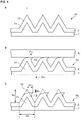
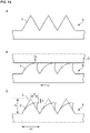
- the inventor proposed, as shown for example in Figure 1 , to compose a seal structure (10) of at least two layers, provide a projecting portion (11) on a first layer (1), and provide a projecting portion (12) on a second layer (2) so that the projecting portion (12) covers at least part of the projecting portion (11). Furthermore, the inventor proposed to inhibit an abnormal deformation of the projecting portion (12) of the second layer (2) or, in particular, an apex of the projecting portion (12) by composing the first layer (1) of a material which is harder than that of the second layer (2). This also improves a force (F10) exerted by the seal structure (10) against, a sealed structure (SI) (e.g. a first sealed structure such as a housing of a connector) (see B of Figure 1 ).
- SI sealed structure
- the present disclosure provides a seal structure including at least a first layer and a second layer.
- the seal structure is configured such that the first layer has at least one first upward projecting portion, that the second layer has at least one first upward projecting portion, such that at least part of the first upward projecting portion of the first layer is covered with the first upward projecting portion of the second layer, and such that a composition material or the material of the first layer is harder than a composition material or the material of the second layer.
- the present invention provides a seal structure with improved sealing capability. Further, the present invention makes it possible to further reduce the size of a seal structure having further improved sealing capability. It should be noted that advantages described herein are not limitative but illustrative and there may be additional advantages.
- the present disclosure provides a seal structure (10) including at least a first layer (1) and a second layer (2).
- the first layer (1) has at least one first upward projecting portion (11)
- the second layer (2) has at least one first upward projecting portion (12). At least part of the first upward projecting portion (11) of the first layer (1) is covered with the first upward projecting portion (12) of the second layer (2).
- a composition material of the first layer (1) is harder than a composition material of the second layer (2).
- the seal structure is herein sometimes referred to as "seal structure of the present disclosure”.
- the seal structure of the present disclosure includes at least a first layer (1) having at least one first upward projecting portion (11) and a second layer (2) having at least one first upward projecting portion (12) (see Figure 1 ).
- the seal structure of the present disclosure may further include a third layer (3) (see Figure 8 ).
- the numbers of projecting portions and layers that may be included in the seal structure of the present disclosure are not limited to any particular numbers.
- the seal structure of the present disclosure may have a shape such as a ring shape, a tube shape, or a porous or apertured shape or form as its overall shape (see Figure 9 ).
- seal structure means a component or a member that may form a seal or sealing in combination with a given “sealed structure” that will be described in detail below.
- the term “sealed structure” means a component or a member that requires a “seal”. It is preferable that the “sealed structure” has such a structure that the "seal structure” of the present disclosure can be inserted into the “sealed structure”. In particular, it is preferable that the “sealed structure” has such a structure that the “seal structure” forms a “seal” by making contact with an inner wall of the "sealed structure".
- An example of the sealed structure is a housing of a connector, a body, a plug, a cord, or an electric wire of a connector that can engage or mate with a housing of the connector, or a fixture thereof. Note, however, that the sealed structure is not limited to these examples.
- the sealed structure is a structure such as a housing of a connector
- the "seal structure" of the present disclosure makes contact with and engages and/or mate with the "sealed structure” so that the "seal structure” of the present disclosure and the “sealed structure” engage or bind with each other.
- the term "seal” means the prevention or inhibition of entry of gas such as moisture and water vapor and/or dust into the space between the "seal structure" of the present disclosure and the "sealed structure".
- the first layer has a lamina or laminar structure, and has at least one "first upward projecting portion".
- the "first upward projecting portion” that may be included in the first layer means a portion raised from a surface of the first layer (and is hereinafter sometimes abbreviated as “upward projecting portion” or simply as “projecting portion”).
- the number of projecting portions that may be provided in the first layer is not limited to any particular number. For example, one to ten projecting portions may be provided in the first layer. Preferably, one to five projecting portions may be provided in the first layer. More preferably, one to three projecting portions may be provided in the first layer.
- the projecting portion may for example be a projection raised from the surface of the first layer to continuously extend.
- the word “upward” of the "upward projecting portion" of the "first layer” means a side on which the "second layer”, which will be described in detail below, is disposed.
- the side on which the "second layer” is disposed is referred to as pointing "upward”.
- the shape of the projecting portion that may be provided in the first layer is not limited to any particular shape. It is preferable that the projecting portion has a triangular shape or a rectangular shape (including a trapezoid) such as a quadrangle in cross-section.
- the projecting portion may have a rounded edge portion. Alternatively, the projecting portion may have a circular arc apex.
- composition material of the first layer is harder than the composition material that may constitute the second layer, which will be described in detail later (hereinafter sometimes referred to as “composition material of the second layer”).
- composition material of the second layer has such flexibility as to more easily deform than the composition material of the first layer in response to external force. That is, the composition material of the first layer has such flexibility as to more hardly deform than the composition material of the second layer.
- composition material of a layer means one or more materials that may form the layer.
- composition material of the first layer contain resin. Any resin can be used in the first layer. For example, it is preferable that rubber such as polybutadiene or silicone be used. Further, resin that can be used in the first layer may be selected depending on temperature.
- first resin resin primarily contained in the composition material of the first layer.
- the hardness of the composition material of the first layer is higher than the hardness of the composition material of the second layer, and is not limited to any particular range.
- Examples of the hardness of the composition material of the first layer include Shore hardness, Rockwell hardness, Vickers hardness, Brinell hardness, durometer hardness, and Barcol hardness.
- the hardness of the composition material of the first layer is not limited to any particular value, and any of the above hardnesses falls within a range of for example 20 to 50, preferably 25 to 45, or more preferably 30 to 40. It is preferable that Shore hardness fall within the above range.
- the hardness of the composition material of the first layer can be changed by a filler, a hardening agent, or other substances that are used in manufacturing the resin.
- the first layer may further include, on an as-needed basis, at least one "second upward projecting portion” or “third upward projecting portion” or other portions that are different in shape from the "first upward projecting portion” provided in the first layer.
- the number of projecting portions that may be provided in the first layer is not limited to any particular number.
- the second layer has a lamina or laminar structure, and has at least one "first upward projecting portion".
- the "first upward projecting portion” that may be included in the second layer means a portion raised from a surface of the second layer (and is hereinafter sometimes abbreviated as “upward projecting portion” or simply as “projecting portion”).
- the number of projecting portions that may be provided in the second layer is not limited to any particular number. For example, one to ten projecting portions may be provided. Preferably, one to five projecting portions may be provided. More preferably, one to three projecting portions may be provided.
- the projecting portion may for example be a projection raised from the surface of the second layer to continuously extend.
- the word “upward” of the "upward projecting portion" of the "second layer” means a direction opposite to the "first layer”.
- the shape of the projecting portion that may be provided in the second layer is not limited to any particular shape. It is preferable that the outer shape, in particular, of the projecting portion be a triangular shape or a rectangular shape (including a trapezoid) such as a quadrangle in cross-section.
- the projecting portion may have a rounded edge portion. Alternatively, the projecting portion may have a circular arc apex. It is preferable that the apex of the projecting portion of the second layer be more rounded than the apex of the projecting portion of the first layer.
- the projecting portion that may be provided in the second layer may extend, for example, so as to meander in a cross-sectional view of the seal structure (see A of Figure 1 ).
- composition material of the second layer be softer than the composition material of the first layer. It is more preferable that the composition material of the second layer contains resin. Any resin can be used in the second layer. For example, it is preferable that rubber such as polybutadiene or silicone be used. Further, resin that can be used in the second layer may be selected depending on temperature.
- second resin resin primarily contained in the composition material of the second layer.
- the hardness of the composition material of the second layer is lower than the hardness of the composition material of the first layer, and is not limited to any particular range.
- Examples of the hardness of the composition material of the second layer include Shore hardness, Rockwell hardness, Vickers hardness, Brinell hardness, durometer hardness, and Barcol hardness.
- the hardness of the composition material of the second layer is not limited to any particular value, and any of the above hardnesses falls within a range of for example 20 to 50, preferably 25 to 45, or more preferably 30 to 40. It is preferable that Shore hardness fall within the above range.
- the hardness of the composition material of the second layer can be changed by a filler, a hardening agent, or other substances that are used in manufacturing the resin.
- the second layer may further include, on an as-needed basis, at least one "second upward projecting portion” or “third upward projecting portion” or other portions that are different in shape from the "first upward projecting portion” provided in the second layer.
- the number of projecting portions that may be provided in the second layer is not limited to any particular number.
- a seal structure of the present disclosure includes at least a first layer and a second layer, and at least part of a first upward projecting portion of the first layer is covered with a first upward projecting portion of the second layer (see, for example, the first upward projecting portion (11) of the first layer (1) and the first upward projecting portion (12) of the second layer (2) shown in Figure 1 ).
- a composition material of the first layer is harder than a composition material of the second layer.
- the seal structure of the present disclosure can be entered or inserted into a sealed structure such as a housing of a connector. With the aforementioned configuration of two projecting portions, the seal structure of the present disclosure can press the sealed structure from within with further improved force (see B of Figure 1 ). For such a reason, the seal structure of the present disclosure can provide further improved sealability. Further, with such a configuration of two projecting portions, the seal structure of the present disclosure can inhibit an abnormal deformation of a projecting portion.
- a seal structure 10 includes a first layer (i.e. a layer denoted by reference numeral "1") and a second layer (i.e. a layer denoted by reference numeral "2").
- the first layer (1) includes at least one first upward projecting portion 11 (hereinafter abbreviated as “projecting portion 11” or simply as “projecting portion”).
- the second layer (2) includes at least one first upward projecting portion 12 (hereinafter abbreviated as “projecting portion 12" or simply as “projecting portion”), too.
- the first layer (1) has three projecting portions of the same shape, and the second layer (2) similarly has three projecting portions 12 of the same shape.
- the projecting portions may be identical or different in shape and dimension to or from one another.
- the projecting portions may be continuously disposed or separately disposed.
- the whole of a surface of a projecting portion 11 of the first layer (1) is covered with a projecting portion 12 of the second layer (2).
- at least part of the surface of the projecting portion 11 of the first layer (1) needs only be covered with the projecting portion 12 of the second layer (2).
- Any part of the projecting portion 11 of the first layer (1) may be covered with the projecting portion 12 of the second layer (2). It is preferable that an apex of the projecting portion 11 of the first layer (1) be covered with the projecting portion 12 of the second layer (2).
- the part of the projecting portion 11 of the first layer (1) that is covered with the projecting portion 12 of the second layer (2) may be determined for each projecting portion of the first layer (1). In other words, the part of the projecting portion 11 of the first layer (1) that is covered with the projecting portion 12 of the second layer (2) may vary from one projecting portion to another.
- first layer (1) and the second layer (2) have substantially the same outer shape
- the seal structure of the present disclosure is not limited to one having such a shape.
- projecting portions of various shapes and dimensions can be independently selected for use.
- the outer shapes of the projecting portion 11 of the first layer (1) and the projecting portion 12 of the second layer (2) are both triangular in cross-section.
- the shapes of the projecting portions are not limited to such shapes.
- the cross-sectional shape of a projecting portion of the first layer (1) and the cross-sectional shape of a projecting portion of the second layer (2) are not limited to any particular combination. Geometric cross-sectional shapes can be each independently selected as appropriate for use in a projecting portion of the first layer (1) and a projecting portion of the second layer (2).
- the apices do not need to be aligned on the straight line L.
- the position of the apex of the projecting portion 11 of the first layer (1) and/or the position of the apex of the projecting portion 12 of the second layer (2) may be off the straight line L. That is, the apex of the projecting portion 11 of the first layer (1) and/or the apex of the projecting portion 12 of the second layer (2) may or may not be present on the straight line L.
- the composition material of the first layer (1) is harder than the composition material of the second layer (2). In other words, the composition material of the second layer (2) is softer than the composition material of the first layer (1).
- the composition material that may constitute the projecting portion 11 of the first layer (1) be harder than the composition material that may constitute the projecting portion 12 of the second layer (2).
- the composition material that may constitute the projecting portion 12 of the second layer (2) be softer than the composition material that may constitute the projecting portion 11 of the first layer (1).
- the composition materials that may constitute the first layer and the second layer both contain resin and the resin primarily contained in the first layer (i.e. the "first resin") be harder than the resin primarily contained in the second layer (i.e. the "second resin") or the second resin be softer than the first resin.
- any resin is used, provided a difference in hardness can be provided between the first resin and the second resin.
- identical types of resin differing in hardness from each other may be used.
- different types of resin differing in hardness from each other may be used.
- the difference between the hardness of the material that may constitute the first layer, specifically the first resin, and the hardness of the material that may constitute the second layer, specifically the second resin fall within a range of preferably 5 to 25 or more preferably 10 to 20.
- the projecting portion of the second layer has "flexibility".
- the term “flexibility” means the property of deforming in response to external force. It is preferable that the projecting portion of the second layer elastically deform.
- the projecting portion 12 of the second layer (2) elastically deforms upon contact with the sealed structure (SI). More specifically, it is preferable that the position of the apex of the projecting portion of the second layer (2) be elastically displaced (see a deformed projecting portion 12' shown in B of Figure 1 ).
- the height of the projecting portion 12 of the second layer (2) specifically the position of its apex, vary or decreases within a range of, for example, less than 50%, for example, in a height direction with respect to the overall height (H0) of the projecting portion 12. More preferably, the position of its apex can vary within a range of 40% or less (see C of Figure 1 ). Even more preferably, the position of its apex can vary within a range of 20% to 30%.
- the position of the apex of the projecting portion 12 can be displaced by H1 in a height direction with respect to the overall height H0 (see the deformed projecting portion 12').
- the value of H1/H0 be less than 1/2. More preferably, the value of H1/H0 is less than or equal to 2/5, or even more preferably, the value of HI/HO is greater than or equal to 1/5 and less than or equal to 3/10.
- the height H0 of the projecting portion of the second layer (2) may vary from one projecting portion to another.
- the overall height of the projecting portion of the first layer (1) may vary from one projecting portion to another. It is preferable that the overall height (H0) of the projecting portion of the second layer (2) be greater than the overall height of the projecting portion of the first layer (1).
- the force (F10) with which the deformed projecting portion 12' presses the sealed structure (S1) can be further increased (see B of Figure 1 ).
- an abnormal deformation of the projecting portion 12 can be inhibited.
- further improvement in sealability can be brought about.
- the presence of the projecting portion 11 of the first layer (1), which is harder than the second layer (2), below the projecting portion 12 of the second layer (2) makes it possible to reduce the overall thickness dimension of the seal structure 10.
- the size of the seal structure 10 can be reduced in a thickness direction. Such a reduction in size may contribute to a reduction in size of the sealed structure, specifically a housing of a connector or other structures.
- the projecting portion 12 of the second layer (2) specifically its apex, vary within a range of less than 50% in a width direction with respect to the overall width (W0) of the projecting portion 12. More preferably, the apex can vary within a range of 40% of less. Even more preferably, the apex can vary within a range of 20% to 30%.
- the position of the apex of the projecting portion 12 of the second layer (2) can be displaced by W1 in a width direction with respect to the overall width W0 (see the deformed projecting portion 12').
- W1/W0 it is preferable that the value of W1/W0 be less than 1/2. More preferably, the value of W1/W0 is less than or equal to 2/5, or even more preferably, the value of W1/W0 is greater than or equal to 1/5 and less than or equal to 3/10.
- the overall width W0 of the projecting portion of the second layer (2) may vary from one projecting portion to another. Further, similarly, the overall width of the projecting portion of the first layer (1) may vary from one projecting portion to another.
- the displacement of the projecting portion 12 of the second layer (2) in a width direction makes it possible to further reduce the dimension of the projecting portion 12 in a width direction and the spacing between projecting portions 12.
- the dimension of the seal structure 10 in a width direction can be further reduced.
- the overall size of the seal structure 10 can be reduced in a width direction. Such a reduction in size may contribute to a reduction in size of the sealed structure, specifically a housing of a connector or other structures.
- width direction means, for example, the direction of the overall width W0 in C of Figure 1 or a horizontal direction on the surface of paper.
- the "width direction" of the seal structure may mean the direction of mating of the seal structure of the present disclosure with the sealed structure.
- a lower surface of the first layer (1) i.e. a surface of the first layer (1) opposite to the surface of the first layer (1) facing the second layer (2)
- the shape of the lower surface of the first layer (1) can be changed as appropriate in conformance with the shape of a surface of another sealed structure (hereinafter sometimes referred to as "second sealed structure") that may make direct contact with the lower surface of the first layer (1) (see Figure 7 ). That is, the lower surface of the first layer (1) is not limited to a flat shape.
- the shape of the apex of the projecting portion 11 of the first layer (1) and/or the shape of the apex of the projecting portion 12 of the second layer (2) may be changed as appropriate in conformance with the shape of a surface of the sealed structure S1 (see B of Figure 1 ). That is, the shape of the apex of the projecting portion 11 of the first layer (1) and/or the shape of the apex of the projecting portion 12 of the second layer (2) is/are not limited to a shape having a sharp edge portion.
- the triangular cross-sectional shape of a projecting portion shown in Figure 1 may be bilaterally asymmetrical. In other words, it may or may not be symmetrical with respect to a perpendicular passing through the apex of the projecting portion.
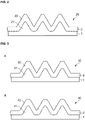
- the apices of projecting portions (21, 22) of a seal structure 20 may have rounded edge portions.
- the projecting portions (21, 22) may be "substantially triangular" in cross-section.
- the projecting portions (21, 22) of the seal structure 20 particularly the projecting portion 22 provided in the second layer (2), having rounded apices as shown in Figure 2 , entry or insertion into a sealed structure can be promoted and the force by which the sealed structure is pressed can be further increased.
- the projecting portion 22 of the second layer (2) may be rounded.
- the projecting portion 21 of the first layer (1) may have a sharp edge portion.
- the triangular cross-sectional shape of a projecting portion shown in Figure 2 may be bilaterally asymmetrical. In other words, it may or may not be symmetrical with respect to a perpendicular passing through the apex of the projecting portion.
- a of Figure 3 shows a seal structure 30 having projecting portions (31, 32) having shapes formed by flattening the apices of triangles or trapezoidal shapes. Since the projecting portions (31, 32) shown in A of Figure 3 have flat apices, the force by which a sealed structure is pressed can be further increased.
- B of Figure 3 shows a seal structure 40 having projecting portions (41, 42) having trapezoidal shapes formed by rounding the edge portions shown in A of Figure 3 (such shapes being hereinafter referred to as "substantially trapezoidal shapes").
- substantially trapezoidal shapes By the projecting portions (41, 42) having substantially trapezoidal shapes, entry or insertion into a sealed structure can be promoted and the force by which the sealed structure is pressed can be further increased.
- the seal structure 40 only the projecting portion 42 of the second layer (2) may be rounded.
- the projecting portion 41 of the first layer (1) may have a sharp edge portion.
- the triangular cross-sectional shape of a projecting portion shown in A or B Figure 3 may be bilaterally asymmetrical. In other words, it may or may not be symmetrical with respect to a perpendicular passing through the apex of the projecting portion.
- a of Figure 4 shows a seal structure 50 having projecting portions (51, 52) having more upright trapezoidal shapes (hereinafter referred to as "substantially quadrangular shapes"). It is preferable that each of the projecting portions (51, 52) have an angle of inclination larger than or equal to 80 degrees and smaller than or equal to 90 degrees. By the projecting portions (51, 52) having substantially quadrangular shapes, the force by which a sealed structure is pressed can be further increased.
- B of Figure 4 shows a seal structure 60 having projecting portions (61, 62) having substantially quadrangular shapes formed by rounding the edge portions shown in A of Figure 3 .
- projecting portions (61, 62) By such projecting portions (61, 62), entry or insertion of the seal structure 60 into a sealed structure can be promoted and the force by which the sealed structure is pressed can be further increased.
- the seal structure 60 only the projecting portion 62 of the second layer (2) may be rounded.
- the projecting portion 61 of the first layer (1) may have a sharp edge portion.
- the shapes of projecting portions of the seal structure may be right triangles.
- a seal structure 70 shown, for example, in A of Figure 5 has first upward projecting portions (71, 72) whose outer shapes are right triangular in cross-section.
- the seal structure 70 can enter into a sealed structure S2 along the direction of an arrow D70.
- the projecting portion 72 of the second layer (2) which is disposed above the projecting portion 71 of the first layer (1), can deform upon contact with an inner wall of the sealed structure S2 (see a deformed projecting portion 72').
- the deformed projecting portion 72' makes it possible to press the sealed structure S2 with a further greater force (F70) (see B of Figure 5 ).
- the shapes of the projecting portions (71, 72) of the seal structure 70 are right triangles. Therefore, for example, as shown in B of Figure 5 , the entry of the seal structure 70 into the sealed structure S2 along the direction of the arrow D70 can be promoted, and the sealed structure S2 can be pressed with a further greater force (F70).
- the projecting portions (71, 72) of the seal structure 70 have slopes in the direction of movement of the seal structure 70 (i.e. the direction of the arrow D70 shown in B of Figure 5 ). Doing so makes it possible to further promote the entry of the seal structure 70 into the sealed structure S2 and further increase the force by which the sealed structure S2 is pressed.
- the apex of the projecting portion 71 of the first layer (1) is on a straight line L1.
- the apex of the projecting portion 72 of the second layer (2) is on a straight line L2.
- the apex of the projecting portion 71 and the apex of the projecting portion 72 may be present or may not be present in the same straight line.
- the difference in position between the apices makes it possible to further promote the entry of the seal structure 70 into the sealed structure S2 and further increase the force by which the sealed structure S2 is pressed (see B of Figure 5 ).
- the projecting portions (71, 72) of the seal structure 70 shown, for example, in A of Figure 5 may have rounded apices (not illustrated). Dosing so makes it possible to further promote the entry of the seal structure 70 into the sealed structure S2.
- the projecting portion 72 of the second layer (2) may be rounded.
- the projecting portion 71 of the first layer (1) may have a sharp edge portion.
- the seal structure of the present disclosure can have projecting portions of various shapes. Projecting portions of such various shapes may be combined as needed for use.
- the present disclosure is not limited to any particular combination of shapes of projecting portions.
- the first layer (1) may further have, for example, at least one second upward projecting portion of a different shape.
- the second layer (2) may further have, for example, at least one second upward projecting portion of a different shape. In such an aspect, it is preferable that at least part of the second upward projecting portion of the first layer (1) be covered with the second upward projecting portion of the second layer (2). Having such a configuration makes it possible to bring about further improvement in sealability.
- the first layer (1) may further have, for example, a third upward projecting portion of a different shape.
- the second layer (2) may further have, for example, a third upward projecting portion of a different shape.
- a composition material of the first upward projecting portion of the first layer (1) may be different in hardness from a composition material of the second upward projecting portion and/or the third upward projecting portion of the first layer (1). Having such a configuration makes it possible to support the second layer (2) more appropriately. Moreover, a more appropriate seal can be provided.
- a composition material of the first upward projecting portion of the second layer (2) may be different in hardness from a composition material of the second upward projecting portion and/or the third upward projecting portion of the second layer (2). Having such a configuration makes it possible to provide a more appropriate seal.
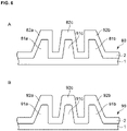
- the first layer (1) has three upward projecting portions (81a, 81b, 81c), and the second layer (2) disposed above the first layer (1) has three upward projecting portions (82a, 82b, 82c), too
- the projecting portion 81a is referred to as “first upward projecting portion”, the projecting portion 81b as “second upward projecting portion”, and the projecting portion 81c as “third upward projecting portion”. They are hereinafter sometimes abbreviated as “projecting portion 81a”, “projecting portion 81b”, and “projecting portion 81c”.
- the projecting portion 82a is referred to as “first upward projecting portion”, the projecting portion 82b as “second upward projecting portion”, and the projecting portion 82c as “third upward projecting portion”. They are hereinafter sometimes abbreviated as “projecting portion 82a”, “projecting portion 82b”, and “projecting portion 82c”.
- the projecting portion 81a and the projecting portion 81b have, as their cross-sectional shapes, shapes formed by flattening the apices of right triangles or substantially trapezoidal shapes.
- the projecting portion 81c is substantially quadrangular in cross-section.
- the outer shapes of the projecting portion 82a and the projecting portion 82b have, as their cross-sectional shapes, shapes formed by flattening the apices of right triangles or substantially trapezoidal shapes.
- the outer shape of the projecting portion 82c is substantially quadrangular in cross-section.
- the seal structure 80 illustrated in A of Figure 6 can enter into a sealed structure from either the projecting portion 82a or the projecting portion 82b of the second layer (2) (not illustrated).
- a structure can be utilized in a seal structure 200 having a ring-type overall shape shown, for example, in A of Figure 9 .
- the ring-type seal structure 200 shown, for example, in A of Figure 9 is inserted into a sealed structure (or a first sealed structure) such as a housing of a connector, it is not necessary to select a direction of insertion of the seal structure.
- Such projecting portions of the seal structure 80 shown, for example, in A of Figure 6 make it possible to further promote the entry of the seal structure 80 into the sealed structure and further increase the force by which the sealed structure is pressed.
- the first layer (1) and the second layer (2) shown in A of Figure 6 may be substantially the same in outer shape.
- the shapes of the first layer (1) and the second layer (2), particularly the shapes of the projecting portions, may be different from each other.
- projecting portions of various shapes can be each independently selected.
- B of Figure 6 shows a seal structure 90 whose projecting portions have rounded edge portions. Since the projecting portions of the seal structure 90 have rounded edge portions, entry of the seal structure 90 into a sealed structure can be further promoted. Further, the apex of the projecting portions, particularly, the projecting portions (92a, 92b, 92c) of the second layer (2), may have circular arc apices.
- a seal structure according to another embodiment of the present disclosure is shown in Figure 7 .
- the first layer (1) has first upward projecting portions 111, specifically three upward projecting portions 111a, 111b, and 111c. They are hereinafter sometimes abbreviated as “projecting portions 111a, 111b, and 111c" or simply as “upward projecting portions” or “projecting portions”.
- the second layer (2) has first upward projecting portions 112, specifically three upward projecting portions 112a, 112b, and 112c. They are hereinafter sometimes abbreviated as “projecting portions 112a, 112b, and 112c" or simply as “upward projecting portions” or “projecting portions”.
- the projecting portions (111, 112) shown in A of Figure 7 are similar to the projecting portions (11, 12) shown in Figure 1 . Further, the projecting portions (111, 112) shown in A of Figure 7 may be replaced as needed by the projecting portions illustrated in any of Figures 2 to 6 .
- the seal structure 110 illustrated in A of Figure 7 may have three downward projecting portions 114, more specifically three downward projecting portions 114a, 114b, and 114c, on the lower surface of the first layer (1) (or the surface of the first layer (1) facing in a direction opposite to the direction of projection of the projecting portion 111 or the surface of the first layer (1) opposite to the surface of the first layer (1) facing the second layer (2)). They are hereinafter sometimes abbreviated as “projecting portions 114a, 114b, and 114c" or simply as “downward projecting portions” or “projecting portions”.
- the number of projecting portions that may be provided on the lower surface of the first layer (1) is not limited to any particular number.
- one to ten projecting portions may be provided.
- one to five projecting portions may be provided.
- More preferably, one to three projecting portions may be provided.
- the projecting portions may for example be projections raised from the lower surface of the first layer to continuously extend.
- the projecting portions (114a, 114b, 114c) that can be provided on the lower surface of the first layer (1) of the seal structure 110 be formed in conformance with the shape of a surface of another sealed structure (e.g. a second sealed structure such as a housing of a connector, a body, a plug, a cord, or an electric wire of a connector, or a fixture thereof) with which the lower surface of the first layer (1) may make contact.
- a second sealed structure such as a housing of a connector, a body, a plug, a cord, or an electric wire of a connector, or a fixture thereof
- the shape of the projecting portions that may be provided on the lower surface of the first layer (1) is not limited to any particular shape. It is preferable that the projecting portions that can be provided on the lower surface of the first layer (1) have triangular shapes or rectangular shapes (including trapezoids) such as quadrangles in cross-section.
- the projecting portions may have bilaterally symmetrical shapes or bilaterally asymmetrical shapes in cross-section.
- the projecting portions may have rounded apices.
- the three projecting portions (114a, 114b, 114c) provided on the lower surface of the first layer (1) illustrated in A of Figure 7 have triangular cross-sectional shapes raised downward.
- a perpendicular La passing through the apex of the upward projecting portion 111a and a perpendicular Ma passing through the apex of the downward projecting portion 114a are aligned with each other.
- a perpendicular Lb passing through the apex of the upward projecting portion 111b and a perpendicular Mb passing through the apex of the downward projecting portion 114b are aligned with each other.
- a perpendicular Lc passing through the apex of the upward projecting portion 111c and a perpendicular Mc passing through the apex of the downward projecting portion 114c are aligned with each other.
- the perpendiculars La, Lb, and Lc do not need to be aligned with the perpendiculars Ma, Mb, and Mc, respectively.
- the position of the apex of a projecting portion 111 on the upper side of the first layer (1) and the position of the apex of a projecting portion 114 on the lower side may be present in the same straight line as illustrated or may not be present in the same straight line.
- B of Figure 7 illustrates a seal structure 120 having projecting portions 124, specifically two downward projecting portions (124a, 124b), on the lower surface of the first layer (1).
- the downward projecting portion 124a is referred to as “first downward projecting portion”
- the downward projecting portion 124b as “second downward projecting portion”. They may be hereinafter sometimes abbreviated as “projecting portion 124a” and “projecting portion 124b.”
- First upward projecting portions 121 raised on the upper side of the first layer (1) of the seal structure 120 may be formed in a manner which is similar to that in which the projecting portions (111a, 111b, 111c) illustrated in A of Figure 7 are formed.
- First upward projecting portions 122 of the second layer (2) of the seal structure 120 may be formed in a manner which is similar to that in which the projecting portions (112a, 112b, 112c) illustrated in A of Figure 7 are formed.
- the two projecting portions (124a, 124b) provided on the lower surface of the first layer (1) illustrated in B of Figure 7 have triangular cross-sectional shapes raised downward.
- the shapes of the projecting portions (124a, 124b) are not limited to the shapes of triangles in cross-section, and may be triangular shapes or rectangular shapes (including trapezoids) such as quadrangles in cross-section.
- the shapes of the projecting portions (124a, 124b) may be bilaterally symmetrical shapes in cross-section as shown, for example, in A of Figure 7 . Further, the projecting portions (124a, 124b) may have rounded apices.
- a perpendicular Ma passing through the apex of the downward projecting portion 124a is not aligned with a perpendicular La passing through the apex of the upward projecting portion 121a.
- a perpendicular Mb passing through the apex of the downward projecting portion 124b is not aligned with a perpendicular Lb passing through the apex of the upward projecting portion 121b.
- Such projecting portions allows the downward projecting portions (124a, 124b) and the upward projecting portions (121a, 121b, 121c) of the first layer (1) to be alternately arranged.
- Such a configuration makes it possible to further reduce the overall thickness of the first layer (1).
- the size of the seal structure 120 can be further reduced in a thickness direction.
- the downward projecting portions of the first layer (1) may have shapes which are similar to those of the upward projecting portions shown, for example, in any of Figures 2 to 6 .
- the seal structure of the present disclosure may further include a given "third layer” as needed.
- the seal structure of the present disclosure may further include a third layer on a lower surface of the first layer (i.e. a surface of the first layer opposite to the surface of the first layer on which the second layer is provided).
- the first layer may be located between the third layer and the second layer. The following describes the third layer in detail.
- the third layer has a lamina or laminar structure, and has at least one "first downward projecting portion".
- the "first downward projecting portion” that may be included in the third layer means a portion raised downward from a surface of the third layer (and is hereinafter sometimes abbreviated as “downward projecting portion” or simply as “projecting portion”).
- the number of projecting portions that may be provided in the third layer is not limited to any particular number. For example, one to ten projecting portions may be provided in the third layer. Preferably, one to five projecting portions may be provided in the third layer. More preferably, one to three projecting portions may be provided in the third layer.
- the projecting portion may for example be a projection raised from the surface of the third layer to continuously extend.
- the word “downward” of the "first downward projecting portion" of the "third layer” means a direction opposite to the "second layer”.
- the shape of the downward projecting portion that may be provided in the third layer is not limited to any particular shape. It is preferable that the outer shape of the projecting portion be a triangular shape or a rectangular shape (including a trapezoid) such as a quadrangle in cross-section.
- the downward projecting portion may have a rounded edge portion. Alternatively, the downward projecting portion may have a circular arc apex. It is preferable that the apex of the downward projecting portion of the third layer be more rounded than the apex of the downward projecting portion that may be provided on the lower surface of the first layer.
- the downward projecting portion that may be provided in the third layer may extend, for example, so as to meander in a cross-sectional view of the seal structure (see Figure 8 ).
- composition material that may constitute the third layer be softer than the composition material of the first layer.
- composition material of the first layer be harder than the composition material of the third layer.
- composition material of the third layer has such flexibility as to more easily deform than the composition material of the first layer in response to external force. That is, the composition material of the first layer has such flexibility as to more hardly deform than the composition material of the third layer.
- composition material of the third layer contain resin. Any resin can be used in the third layer, and for example, it is preferable that rubber such as polybutadiene or silicone be used. Further, resin that can be used in the third layer may be selected depending on temperature.
- third resin resin primarily contained in the composition material of the third layer.
- the hardness of the composition material of the third layer is lower than the hardness of the composition material of the first layer, and is not limited to any particular range.
- Examples of the hardness of the composition material of the third layer include Shore hardness, Rockwell hardness, Vickers hardness, Brinell hardness, durometer hardness, and Barcol hardness.
- the hardness of the composition material of the third layer is not limited to any particular value, and any of the above hardnesses falls within a range of for example 20 to 50, preferably 25 to 45, or more preferably 30 to 40. It is preferable that Shore hardness or durometer hardness fall within the above range.
- the hardness of the composition material of the third layer can be changed by a filler, a hardening agent, or other substances that are used in manufacturing the resin.
- the third layer may further include, on an as-needed basis, at least one "second downward projecting portion” or “third downward projecting portion” or other portions that are different in shape from the "first downward projecting portion" of the third layer.
- the first layer has at least one first downward projecting portion on a side thereof facing the third layer.
- the third layer has at least one first downward projecting portion, too. It is preferable that at least part of the first downward projecting portion of the first layer be covered with the first downward projecting portion of the third layer.
- a composition material of the first layer be harder than a composition material of the third layer. In other words, it is preferable that the composition material of the third layer be softer than the composition material of the first layer.
- Such a configuration makes it possible to form a more appropriate seal with a sealed structure (or a second sealed structure) that makes contact with the third layer.
- the whole of a surface of the first downward projecting portion of the first layer may be covered with the first downward projecting portion of the third layer.
- only part of the surface of the first downward projecting portion of the first layer may be covered with the first downward projecting portion of the third layer. It is preferable that the apex of the first downward projecting portion of the first layer be covered with the first downward projecting portion of the third layer.
- the composition material of the first layer contains resin (e.g. a first resin), and the composition material of the third layer contains resin (e.g. a third resin), too. It is preferable that the third resin be softer than the first resin. In other words, it is preferable that the first resin be harder than the third resin.
- Such a configuration allows the third layer and the sealed structure (or the second sealed structure) to make contact with each other more appropriately, making it possible to bring about further improvement in sealability.
- any resin is used, provided a difference in hardness can be provided between the third resin and the first resin.
- the third resin and the first resin identical types of resin differing in hardness from each other may be used.
- different types of resin differing in hardness from each other may be used.
- the difference between the hardness of the material that may constitute the third layer, specifically the third resin, and the hardness of the material that may constitute the first layer, specifically the first resin fall within a range of preferably 5 to 25 or more preferably 10 to 20.
- a of Figure 8 shows a seal structure 130 having a third layer (3).
- the seal structure 130 can be formed by disposing the third layer (3) on the lower surface of the first layer (1) of the seal structure 110 illustrated in A of Figure 7 already mentioned (i.e. the surface of the first layer (1) facing away from the second layer (2)).
- downward projecting portions 133 (specifically first downward projecting portions 133a, 133b, 133c) of the third layer (3) are disposed on surfaces of downward projecting portions 134 (specifically first downward projecting portions 134a, 134b, 134c) provided in the first layer (1).
- the positions of the apices of the downward projecting portions 134 of the first layer (1) and the positions of the apices of the downward projecting portions 133 of the third layer (3) are aligned with each other on perpendiculars Ma, Mb, and Mc, respectively, they may not be aligned with each other.
- B of Figure 8 shows a seal structure 140 having a third layer (3).
- the seal structure 140 can be formed by disposing the third layer (3) on the lower surface of the first layer (1) of the seal structure 120 illustrated in B of Figure 7 already mentioned (i.e. the surface of the first layer (1) facing away from the second layer (2)).
- downward projecting portions 143 (specifically a first downward projecting portion 143a and a second downward projecting portion 143b) of the third layer (3) are disposed on surfaces of downward projecting portions 144 (specifically a first downward projecting portion 144a and a second downward projecting portion 144b) provided in the first layer (1).
- the positions of the apices of the downward projecting portions 144 of the first layer (1) and the positions of the apices of the downward projecting portions 143 of the third layer (3) are aligned with each other on perpendiculars Ma and Mb, respectively, they may not be aligned with each other.
- the downward projecting portions of the third layer (3) may have shapes which are similar to those of the upward projecting portions of the second layer (2) shown, for example, in any of Figures 2 to 6 .
- Figure 9 shows the overall shapes of seal structures of the present disclosure. Examples include (A) a ring-type seal structure 200, (B) a tube-type seal structure 300, (C) a porous or apertured seal structure 400, or other seal structures.
- a of Figure 9 shows (a) the front, (b) the side, and (c) the rear of the ring-type seal structure 200. Projecting portions of the seal structure 200 can be seen on the side (b) of A of Figure 9 .
- B of Figure 9 is an isometric view showing the overall shape of the tube-type seal structure 300.
- C of Figure 9 shows (a) the front, (b) the side, and (c) the rear of the porous seal structure 400. Projecting portions of the seal structure 400 can be seen on the side (b) of C of Figure 9 .
- Figure 10 shows the ring-type seal structure 200 ((A) front, (B) side, (C) rear, (D) bottom or top).
- the ring-type seal structure 200 has an annular overall structure.
- the seal structure 200 has three projections (201, 202, 203) provided as projecting portions on the outer periphery thereof and three projections (204, 205, 206) provided as projecting portions on the inner periphery (see E of Figure 10 ).
- the seal structure 200 can form a seal, for example, by being placed between a housing of a connector (or a first sealed structure) and a connector body (or a second sealed structure) that can mate with the housing of the connector. It is preferable that the seal structure 200 be fitted to the connector body or the like first then inserted into the connector housing.
- E of Figure 10 schematically shows a simplified cross-section of the seal structure 200 as taken along line x-x in A of Figure 10 .
- the projecting portions 201, 202, and 203 schematically show projecting portions that may be provided in the "second layer” of the present disclosure.
- the projecting portions 204, 205, and 206 schematically show the projecting portions that may be provided in the "first layer” or "third layer” of the present disclosure.
- the cross-section of E of Figure 10 does not show a boundary between the first layer, the second layer, and/or the third layer.
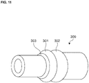
- FIG 11 is an isometric view schematically showing the tube-type seal structure 300.
- the tube-type seal structure 300 has a tubular overall structure, and has two projections (301, 302) as projecting portions on the outer periphery thereof.
- the projecting portions 301 and 302 correspond to the projecting portions that may be provided in the "second layer” of the present disclosure.
- a projecting portion 303 corresponds to the projecting portion of the "first layer” of the present disclosure.
- the projecting portion 301 is formed on the upper side of the projecting portion 303.
- the tube-type seal structure 300 is configured such that a sealed structure (or a second sealed structure) such as a cord, an electric wire, or a fixture thereof can be fixedly placed in a through-hole provided inside the tube-type seal structure 300.
- a sealed structure or a second sealed structure
- the inside shape of the through-hole i.e. the shape of a surface of the "first layer” or “third layer” of the present disclosure opposite to the "second layer” (see Figures 7 and 8 )
- the tube-type seal structure 300 allows a seal to be formed by placing a sealed structure (or a second sealed structure) such as a cord, an electric wire, or a fixture thereof into the through-hole and, furthermore, inserting the tube-type seal structure 300 into a sealed structure (or a first sealed structure) such as a hosing of a connector.
- a sealed structure or a second sealed structure
- a sealed structure or a first sealed structure
- FIG 12 shows the porous seal structure 400 ((A) front, (B) side, (C) rear, (D) partial cross-section).
- the porous seal structure 400 is for example in the shape of a plate, has a plurality of through-holes, and has three projections (401, 402, 403) provided as projecting portions on the outer periphery and two projections (404, 405) provided as projecting portions inside the through-holes (see D of Figure 12 ).
- the porous seal structure 400 allows a seal to be formed by placing a sealed structure (or a second sealed structure) such as a cord, an electric wire, or a fixture thereof into the plurality of through-holes and, furthermore, inserting the porous seal structure 400 into a sealed structure (or a first sealed structure) such as a hosing of a connector.
- D of Figure 12 schematically shows a simplified cross-section of an encircled portion of the seal structure 400 shown in B of Figure 12 .
- the projecting portions 401, 402, and 403 schematically show projecting portions that may be provided in the "second layer” of the present disclosure.
- the projecting portions 404 and 405 schematically show projecting portions that may be provided in the "first layer” or “third layer” of the present disclosure (however, projecting portions opposite to the "second layer” of the present disclosure).
- the partial cross-section of D of Figure 12 does not show a boundary between the first layer, the second layer, and/or the third layer.
- a seal structure of the present disclosure is not limited to the above embodiments.
- the foregoing embodiments may be appropriately combined as needed for use.
- the shapes of projecting portions may be appropriately combined as needed for use.
- a seal structure of the present disclosure can be manufactured by primarily utilizing "two-color molding".
- the first layer and the second layer and, when needed, the third layer can be formed by "two-color molding”.
- the projecting portions can be each independently formed by "two-color molding”.
- the seal structure of the present disclosure be a laminated body. It is more preferable that the seal structure of the present disclosure be a laminated body integrally manufactured by two-color molding.
- a seal structure of the present disclosure is applicable, for example, to various fields that require properties such as a waterproofing property, a dustproofing property, and/or airtightness.
- the seal structure of the present disclosure can be used especially in a connector for use in an electrical connection, particularly a housing of a connector.
Landscapes
- Engineering & Computer Science (AREA)
- General Engineering & Computer Science (AREA)
- Mechanical Engineering (AREA)
- Chemical & Material Sciences (AREA)
- Dispersion Chemistry (AREA)
- Gasket Seals (AREA)
- Connector Housings Or Holding Contact Members (AREA)
Applications Claiming Priority (1)
| Application Number | Priority Date | Filing Date | Title |
|---|---|---|---|
| JP2020169291A JP7503990B2 (ja) | 2020-10-06 | 2020-10-06 | シール構造体 |
Publications (1)
| Publication Number | Publication Date |
|---|---|
| EP3982015A1 true EP3982015A1 (de) | 2022-04-13 |
Family
ID=78078033
Family Applications (1)
| Application Number | Title | Priority Date | Filing Date |
|---|---|---|---|
| EP21200625.8A Pending EP3982015A1 (de) | 2020-10-06 | 2021-10-04 | Dichtungsstruktur |
Country Status (4)
| Country | Link |
|---|---|
| US (1) | US12080972B2 (de) |
| EP (1) | EP3982015A1 (de) |
| JP (1) | JP7503990B2 (de) |
| CN (1) | CN114382890B (de) |
Families Citing this family (2)
| Publication number | Priority date | Publication date | Assignee | Title |
|---|---|---|---|---|
| DE102022128263A1 (de) | 2022-10-25 | 2024-04-25 | Valeo Powertrain Gmbh | Hydraulikaggregat und Verfahren zum Montieren eines Hydraulikaggregats |
| JP2024178572A (ja) * | 2023-06-13 | 2024-12-25 | ダイキンファインテック株式会社 | シール材およびシール構造体 |
Citations (7)
| Publication number | Priority date | Publication date | Assignee | Title |
|---|---|---|---|---|
| US2451070A (en) * | 1945-03-12 | 1948-10-12 | Us Stoneware Co | Fluid-retaining joint and method of making the same |
| US3150876A (en) * | 1961-11-14 | 1964-09-29 | Wylie M Lafferty | Sealing structure for pipe joints |
| US20020074741A1 (en) * | 2000-11-30 | 2002-06-20 | Malcolm Mann, Inc. | Annular gasket |
| US20040041347A1 (en) * | 2000-11-30 | 2004-03-04 | Beach Jefferey Kurtis | Permanently lubricated gasket |
| JP2004119022A (ja) | 2002-09-24 | 2004-04-15 | Nok Corp | コネクターシール |
| JP2005005035A (ja) | 2003-06-10 | 2005-01-06 | Sumitomo Wiring Syst Ltd | 防水コネクタ用ゴム栓 |
| US20190011049A1 (en) * | 2017-07-06 | 2019-01-10 | Nippon Pillar Packing Co., Ltd. | Spiral wound gasket |
Family Cites Families (38)
| Publication number | Priority date | Publication date | Assignee | Title |
|---|---|---|---|---|
| US1095810A (en) * | 1913-10-21 | 1914-05-05 | Reno Mfg Company | Sealing-ring. |
| USRE24478E (en) * | 1954-02-01 | 1958-05-27 | Flexible gaskets | |
| US3166332A (en) | 1961-05-26 | 1965-01-19 | Olson Richard Laurence | Pressure assembly comprising a sealing strip of elastomeric material having compressible gas cells |
| US3511685A (en) * | 1964-03-10 | 1970-05-12 | Minnesota Rubber Co | Method of making sealing rings |
| LU54653A1 (de) * | 1967-10-11 | 1969-07-03 | ||
| US3787078A (en) * | 1972-08-03 | 1974-01-22 | R Williams | Manhole base section for sewer lines |
| US3854736A (en) * | 1972-10-27 | 1974-12-17 | Farnam F Co | Densified convolute gasket structure |
| US3759285A (en) * | 1972-12-11 | 1973-09-18 | R Yoakum | Pre cast base and method for manholes and the like |
| US4664421A (en) * | 1986-08-29 | 1987-05-12 | Jones William D | Forgiving profile pipe gasket |
| US5169161A (en) * | 1991-09-19 | 1992-12-08 | Hail Mary Rubber Co., Inc. | Symmetrical gasket for pipe joints |
| DE4240661B4 (de) * | 1992-12-03 | 2006-11-23 | STE Gesellschaft für Dichtungstechnik mbH | Flüssigkeitsabdichtung bei Dichtungen mit vorgegebener Dickenverteilung |
| US5700038A (en) * | 1995-10-18 | 1997-12-23 | Gnesys, Inc. | Pipe connection assembly |
| DE19633627A1 (de) * | 1996-08-21 | 1998-02-26 | Dischler Helmut | Kupplungsvorrichtung für die Herstellung einer Rohrverbindung |
| JP3898791B2 (ja) * | 1997-01-13 | 2007-03-28 | 日本ラインツ株式会社 | シリンダヘッドガスケット |
| US7469905B2 (en) * | 2000-11-30 | 2008-12-30 | Springseal Inc. | Permanently lubricated film gasket and method of manufacture |
| TWI259501B (en) * | 2000-12-07 | 2006-08-01 | Shinetsu Polymer Co | Seal and substrate container using same |
| US6676136B2 (en) * | 2001-08-21 | 2004-01-13 | Press-Seal Gasket Corporation | Flexible waterstop ring |
| DE10252141A1 (de) * | 2002-11-09 | 2004-07-01 | Prominent Dosiertechnik Gmbh | Flachdichtungsring |
| JP2004311254A (ja) * | 2003-04-08 | 2004-11-04 | Matsushita Electric Ind Co Ltd | 燃料電池のガスシール構造 |
| JP2005016603A (ja) * | 2003-06-25 | 2005-01-20 | Nsk Ltd | 密封装置及び密封装置付転がり軸受ユニット |
| DE102005014297A1 (de) * | 2005-03-24 | 2006-10-05 | Endress + Hauser Gmbh + Co. Kg | Gehäuse für ein elektronisches Gerät und Dichtring für ein Gehäuse |
| CN101454599B (zh) * | 2006-03-28 | 2015-12-16 | 界面性能材料公司 | 由各种材料形成的垫片 |
| US7374210B2 (en) * | 2006-10-17 | 2008-05-20 | Jeffery Gene Staskal | Hydro penetration prevention sleeve |
| JP2010080106A (ja) | 2008-09-24 | 2010-04-08 | Sumitomo Wiring Syst Ltd | コネクタ |
| KR20090064540A (ko) * | 2009-03-13 | 2009-06-19 | 다이키 고교 가부시키가이샤 | 개스킷 |
| CN201973238U (zh) * | 2010-09-26 | 2011-09-14 | 北京北方微电子基地设备工艺研究中心有限责任公司 | 密封圈及应用该密封圈的等离子体加工设备 |
| US8864181B2 (en) * | 2011-02-16 | 2014-10-21 | Sensus Spectrum, Llc | Split-ring gland pipe coupling with corrugated armor |
| JP2015078007A (ja) * | 2013-10-18 | 2015-04-23 | 大塚テクノ株式会社 | 容器開口封止具および容器 |
| JP5590210B1 (ja) * | 2013-10-22 | 2014-09-17 | 富士ゼロックス株式会社 | 封止部材および画像形成装置 |
| US10502320B2 (en) * | 2014-09-02 | 2019-12-10 | Rohr, Inc. | Spring retainer seal |
| JP6314910B2 (ja) * | 2015-05-28 | 2018-04-25 | 住友電装株式会社 | ゴム栓アッシー |
| JP6559554B2 (ja) | 2015-11-24 | 2019-08-14 | 矢崎総業株式会社 | シール部材 |
| KR20190005860A (ko) * | 2016-05-10 | 2019-01-16 | 엔오케이 가부시키가이샤 | 개스킷 및 그 장착방법 |
| JP6768822B2 (ja) * | 2016-11-07 | 2020-10-14 | Nok株式会社 | ガスケット及びその製造方法 |
| JP6902988B2 (ja) * | 2017-11-30 | 2021-07-14 | 日本ピラー工業株式会社 | ガスケットの製造方法 |
| CN209262238U (zh) | 2018-10-26 | 2019-08-16 | 广州机械科学研究院有限公司 | 波纹密封垫片 |
| CN210970025U (zh) | 2019-09-05 | 2020-07-10 | 宁波瑞升密封材料有限公司 | 一种波纹垫片石墨滚压机 |
| US11608895B2 (en) * | 2020-10-29 | 2023-03-21 | Aptiv Technologies Limited | Dispensing seal |
-
2020
- 2020-10-06 JP JP2020169291A patent/JP7503990B2/ja active Active
-
2021
- 2021-09-30 CN CN202111157092.0A patent/CN114382890B/zh active Active
- 2021-10-04 EP EP21200625.8A patent/EP3982015A1/de active Pending
- 2021-10-06 US US17/495,019 patent/US12080972B2/en active Active
Patent Citations (7)
| Publication number | Priority date | Publication date | Assignee | Title |
|---|---|---|---|---|
| US2451070A (en) * | 1945-03-12 | 1948-10-12 | Us Stoneware Co | Fluid-retaining joint and method of making the same |
| US3150876A (en) * | 1961-11-14 | 1964-09-29 | Wylie M Lafferty | Sealing structure for pipe joints |
| US20020074741A1 (en) * | 2000-11-30 | 2002-06-20 | Malcolm Mann, Inc. | Annular gasket |
| US20040041347A1 (en) * | 2000-11-30 | 2004-03-04 | Beach Jefferey Kurtis | Permanently lubricated gasket |
| JP2004119022A (ja) | 2002-09-24 | 2004-04-15 | Nok Corp | コネクターシール |
| JP2005005035A (ja) | 2003-06-10 | 2005-01-06 | Sumitomo Wiring Syst Ltd | 防水コネクタ用ゴム栓 |
| US20190011049A1 (en) * | 2017-07-06 | 2019-01-10 | Nippon Pillar Packing Co., Ltd. | Spiral wound gasket |
Also Published As
| Publication number | Publication date |
|---|---|
| JP7503990B2 (ja) | 2024-06-21 |
| US12080972B2 (en) | 2024-09-03 |
| US20220109265A1 (en) | 2022-04-07 |
| CN114382890A (zh) | 2022-04-22 |
| CN114382890B (zh) | 2025-03-18 |
| JP2022061342A (ja) | 2022-04-18 |
Similar Documents
| Publication | Publication Date | Title |
|---|---|---|
| EP3982015A1 (de) | Dichtungsstruktur | |
| EP3168508B1 (de) | Dichtung | |
| JP6532242B2 (ja) | シール材 | |
| CN102823077B (zh) | 防水插头 | |
| US20200127405A1 (en) | Movable connector | |
| JP6056343B2 (ja) | 密封構造 | |
| KR101357189B1 (ko) | 소형 전자기기용 방수 개스킷 | |
| JP7715748B2 (ja) | ガスケット及び封止構造 | |
| JP7599569B2 (ja) | ガスケット | |
| US7931279B2 (en) | Metal fixture for dust cover | |
| JP4128802B2 (ja) | 耐プラズマ性シール | |
| JP7391675B2 (ja) | 密封装置 | |
| CN117855930A (zh) | 密封部件和连接器组件 | |
| JP5081679B2 (ja) | 防水シール構造およびこのシール構造を設けた機器 | |
| US7608955B2 (en) | Motor | |
| CN214014273U (zh) | 玻璃盖板、手机屏幕、前壳以及智能手机 | |
| JP4453279B2 (ja) | ガスケット | |
| JP5373160B2 (ja) | 防水シール構造およびこのシール構造を設けた機器 | |
| CN213711868U (zh) | 密封装置及密封结构体 | |
| JP6022891B2 (ja) | フィルム一体型防水パッキン | |
| JP7411221B2 (ja) | シール部材 | |
| JP7459249B2 (ja) | 密封装置 | |
| KR20250040973A (ko) | 실링재 및 실링 구조체 | |
| JP2026013523A (ja) | ガスケットおよび密封構造 | |
| JP2025014700A (ja) | 分割ガスケット、分割ガスケットの取付構造、及び、分割ガスケットの組付方法 |
Legal Events
| Date | Code | Title | Description |
|---|---|---|---|
| PUAI | Public reference made under article 153(3) epc to a published international application that has entered the european phase |
Free format text: ORIGINAL CODE: 0009012 |
|
| STAA | Information on the status of an ep patent application or granted ep patent |
Free format text: STATUS: THE APPLICATION HAS BEEN PUBLISHED |
|
| AK | Designated contracting states |
Kind code of ref document: A1 Designated state(s): AL AT BE BG CH CY CZ DE DK EE ES FI FR GB GR HR HU IE IS IT LI LT LU LV MC MK MT NL NO PL PT RO RS SE SI SK SM TR |
|
| STAA | Information on the status of an ep patent application or granted ep patent |
Free format text: STATUS: REQUEST FOR EXAMINATION WAS MADE |
|
| 17P | Request for examination filed |
Effective date: 20220711 |
|
| RBV | Designated contracting states (corrected) |
Designated state(s): AL AT BE BG CH CY CZ DE DK EE ES FI FR GB GR HR HU IE IS IT LI LT LU LV MC MK MT NL NO PL PT RO RS SE SI SK SM TR |
|
| STAA | Information on the status of an ep patent application or granted ep patent |
Free format text: STATUS: EXAMINATION IS IN PROGRESS |
|
| 17Q | First examination report despatched |
Effective date: 20230413 |
|
| RAP3 | Party data changed (applicant data changed or rights of an application transferred) |
Owner name: TE CONNECTIVITY JAPAN G.K. |